Co-Combustion of Fast Pyrolysis Bio-Oil Derived from Coffee Bean Residue and Diesel in an Oil-Fired Furnace


1
Department of Mechanical Engineering, Kun Shan University, Tainan 71070, Taiwan
2
Department of Mechanical Engineering, National Cheng Kung University, Tainan 70101, Taiwan
3
Research Center for Energy Technology and Strategy, National Cheng Kung University, Tainan 70101, Taiwan
*
Authors to whom correspondence should be addressed.
Appl. Sci. 2017, 7(10), 1085; https://doi.org/10.3390/app7101085
Submission received: 26 August 2017
/
Revised: 7 October 2017
/
Accepted: 16 October 2017
/
Published: 19 October 2017
(This article belongs to the Special Issue Selected Papers from IEEE ICASI 2017)
Abstract
:The combustion characteristics of co-firing bio-oil produced from the fast pyrolysis process of coffee bean residue and diesel in a 300-kWth oil-fired furnace are investigated. Using bio-oil to completely replace fossil fuels has limitations since bio-oil has undesirable properties, such as high water and oxygen contents, high viscosity, and low heating value. However, a low blend ratio of bio-oil used as a substitute for petroleum-derived oil has advantages; i.e., it can be easily combusted in existing furnaces without modifications. Thus, a promising solution is the partial substitution of diesel with bio-oil, rather than completely replacing it. A furnace test is performed for diesel alone and bio-oil/diesel blends with 5 vol % bio-oil. The results show that excellent stable combustion is observed during the co-firing test. Compared with diesel, with 5 vol % bio-oil content in the blends, both the wall temperature and gas temperature drop only slightly and exhibit similar furnace temperature distribution; meanwhile, comparable NO emissions (smaller than 57 ppm) are obtained, and lower CO2 emissions are achieved because biomass is both carbon neutral and renewable. Moreover, SO2 and CO emissions under these two burning conditions are very low; SO2 and CO emissions are smaller than 6 and 35 ppm, respectively.
1. Introduction
Biomass is one of the most commonly used forms of renewable energy around the world. It is a C-based organic material that primarily comes from plants such as crops and wood and also from byproducts such as agricultural waste. Biomass absorbs carbon dioxide from the atmosphere during growth in the process of photosynthesis and emits the same amount of carbon dioxide into the atmosphere during combustion. The utilization of biomass energy provides a number of benefits compared to fossil fuels, especially those related to environmental aspects, since biomass is a renewable and CO2-neutral fuel [1]. Replacing fossil fuels with sustainably-produced biomass has the potential to significantly reduce SOx and NOx emissions, which are acid rain precursors, because most biomass fuels have low levels of sulphur and nitrogen content [2].
Pyrolysis is a thermal decomposition process of organic materials that occurs through the application of intense heat in the absence of oxygen, leading to the production of biogas, bio-oil, and biochar. Thermochemical conversion of lignocellulosic biomass into bio-oil through fast pyrolysis process is considered one of the promising routes to replace conventional fossil oil [3]. Fast pyrolysis bio-oil (FPBO) is produced through rapid heating of organic material to temperatures of 500–600 °C to achieve decomposition in the absence of oxygen [4]. FPBO is a black-brownish organic liquid obtained by the condensation of gaseous pyrolysis products during the fast pyrolysis of biomass. It can be used as a fuel directly or can be upgraded to form a higher-energy-density liquid for transportation, heating, and power generation [5,6,7,8]. Currently, FPBOs are being developed as potential substitutes for conventional fossil fuel to generate heat and power in diesel engines, gas turbines, and boilers, as well as in power generation and industrial processes [9].
Much attention has been paid to the use of biodiesel in diesel engines [10,11,12,13,14]. However, relatively few studies have been carried out on the performance and pollutant emissions of diesel engines [15] or industrial applications [16] using bio-oil as fuel. In particular, research on liquid biofuels for use in furnaces or boilers is quite rare [17]. Zeb et al. [18] performed a computational fluid dynamics (CFD) analysis on the combustion behavior of a bio-oil derived from macroalgae (Saccharina japonica) in a commercial 100 MWe generation plant. The thermal efficiency of the bio-oil (86.0%) was found to be quite similar to that of heavy fuel oil (HFO) (87.1%), suggesting that the HFO could be fully replaced by the bio-oil. Lee et al. [19] investigated the combustion performance of a residential-scale hot water boiler fueled with a blend with 20% soy bean methyl ester (SOME) in No. 2 fuel oil. It was concluded that the NOx emissions were quite similar, and an approximately 20% reduction in SO2 emissions was observed when compared to the use of the pure No. 2 fuel. Zheng et al. [9] explored the combustion characteristics of fast pyrolysis bio-oil produced from rice husk in a 43.5 kWth-capacity (thermal power) combustion chamber. They reported that the CO concentration decreased with the equivalence ratio (the ratio of the fed air to the required air for complete combustion), that the NOx concentration slightly increased with the equivalence ratio, and that the SOx concentration was very low (smaller than 30 ppm). Daho et al. [20] investigated the combustion characteristics of heating fuel oil and cottonseed oil in a modified burner. They found that the CO, O2, CO2, NOx, SO2, and PAHs (polycyclic aromatic hydrocarbons) emissions were similar for these two fuels under optimized atomization and granulometry conditions. Park et al. [2] conducted a CFD analysis to investigate the combustion characteristics of heavy fuel oil (HFO) and a palm-based bioliquid (BL) in a 100 MWe-capacity boiler. They reported that the BL-firing case exhibited lower radiation and more uniform temperature in the combustion zone when compared with the HFO-firing case. Also, a significant reduction in NOx and SOx emissions was achieved owing to the inherently low sulphur and nitrogen content. More recently, Park et al. [21] performed a CFD analysis on BL co-firing with HFO in a 400 MWe power plant with a wall-firing boiler. They used a BL blend of palm oil, its residue, and animal fat at a 20% co-firing ratio and reported that lower soot formation decreased radiation on the furnace wall in the BL co-firing.
The development of renewable bio-energy has recently attracted a lot of attention, where especially, biowaste conversion to energy has been of great interest [22,23,24,25,26] due to the depletion of fossil fuels and the associated negative environmental impacts. A large amount of a byproduct called spent coffee grounds is generated after brewing coffee. Spent coffee grounds are the primary waste product generated by thermal water extraction from roasted coffee beans [27]. In Taiwan, coffee consumption is gradually growing. Currently, the Taiwanese population consumes 2.85 billion cups of coffee (which generate about 34,200 tons of coffee ground residue) every year. It is estimated that 14,275 kL of bio-oil can be derived from the above coffee ground residue per year. Coffee grounds are expected to be an essential energy source due to consumption growth and the fact that this product has a higher heating value than woody biomass [28].
The use of FPBO to completely replace fossil fuels has some limitations since it has negative properties including higher water and oxygen contents, higher viscosity, poor volatility, and a low heating value. However, a low blend ratio of bio-oil to substitute for petroleum-derived oil has advantages. For instance, it can be easily combusted in existing industrial boilers and furnaces without modifications. Moreover, biofuels like biodiesel, ethanol and butanol are made from agricultural crops, leading to food security issues and an increase in energy costs. On the other hand, bio-oil derived from fast pyrolysis of non-edible feedstocks (e.g., coffee bean residue) does not cause the problem of food security and an increase in energy prices. Thus, a promising solution is the partial substitution of conventional diesel fuel with bio-oil, rather than completely replacing it. However, there is still limited amount of data in the literature regarding the combustion characteristics of co-firing FPBO and diesel for application in furnaces. This study is aimed at investigating the combustion characteristics and pollutant emissions of co-combustion bio-oil (produced from the fast pyrolysis process of coffee bean residue) and diesel at a co-firing ratio of 5 vol % FPBO in an oil-fired furnace.
2. Experimental
2.1. Preparation of Test Fuel
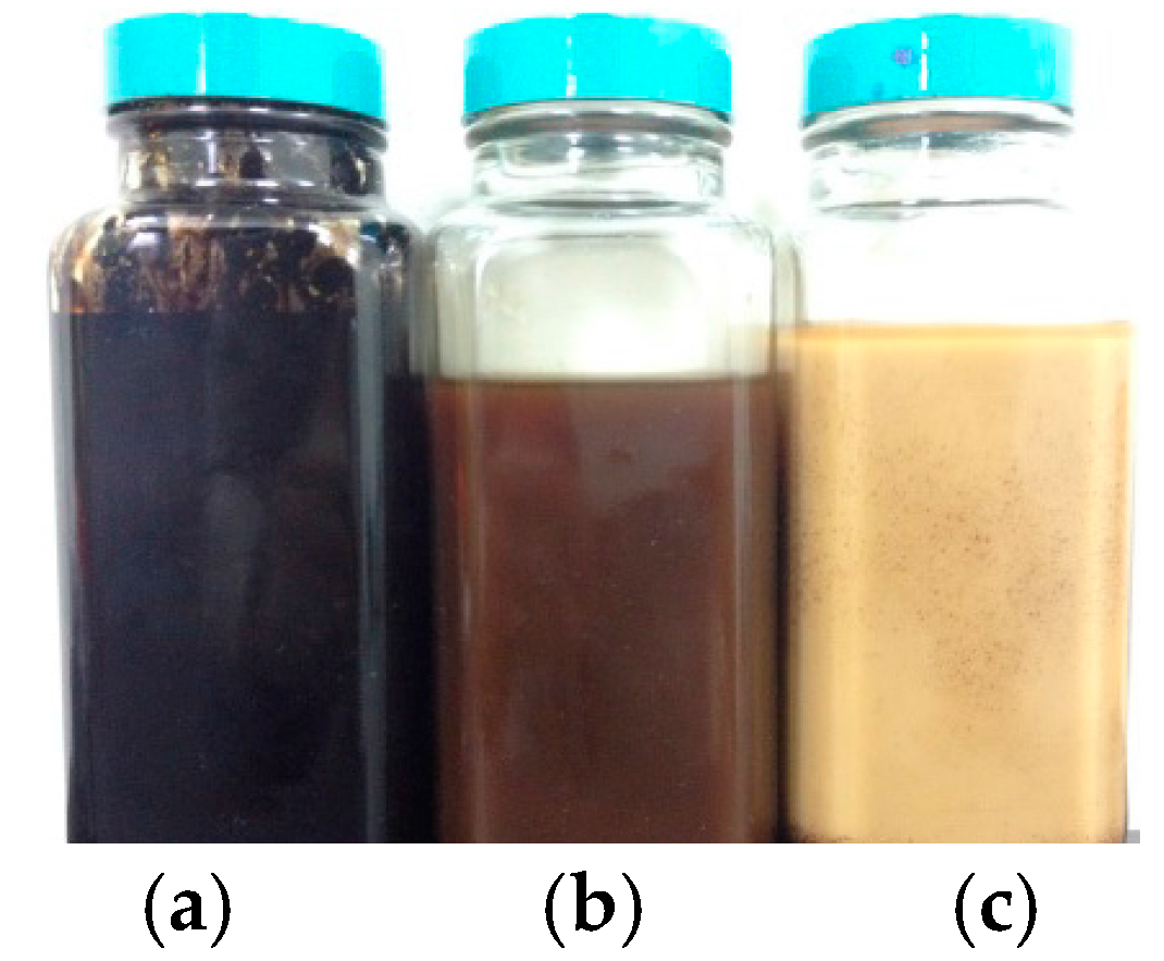
The fast pyrolysis bio-oil (FPBO) was produced from the fast pyrolysis of a bio-waste source (coffee bean residue) in a fluidized bed reactor system using CO2 as the fluidized gas [29]. Two phases of FPBO were produced, i.e., an oily-phase (Figure 1a) and an aqueous-phase (Figure 1b), depending on the condensation collection temperature. More specifically, the oily phase was collected mainly at higher condensation temperatures (380–400 K), whereas the aqueous phase required lower condensation temperatures (300–330 K). The FPBO was prepared by blending the oily-phase oil and aqueous-phase oil at a ratio of 50:50 by vol %. Emulsification was necessary because bio-oil produced from a cellulosic biomass cannot be directly mixed with diesel. Surfactants were added to support the mixing stability. A surfactant molecule has two parts: one has affinity for water and the other has affinity for oil. The HLB (hydrophilic-lipophilic balance) of a surfactant is a measure of the degree to which it is hydrophilic or lipophilic, and it is determined by calculating values for the different regions of the molecule. Surfactants are classified according to their HLB value, which affects their usage. An optimal value of HLB is necessary for the stabilization of emulsion [30]. Span 80 (sorbitan monooleate; C24H44O6; HLB value of 4.3) is a lipophilic emulsifier, whereas Tween 80 (polyoxyethylene sorbitan monoleate; C32H60O10; HLB value of 15) is a hydrophilic emulsifier. According to well established emulsification principles, a combination of a high and low emulsifier is more effective than the use of a single emulsifier. In this study, we found that the emulsion of FPBO/diesel with HLB 9.9 results in the highest stability when using Span 80 and Tween 80 together. Therefore, Span 80 and Tween 80 were added to the diesel and bio-oil, respectively. Firstly, a 1.5 vol % of Span 80 was blended with the diesel, and a 1.5 vol % Tween 80 was blended with the FPBO (prepared by blending the oily-phase oil and aqueous-phase oil at a ratio of 50:50 by vol %). Then, emulsification (Figure 1c) was subsequently conducted to produce superior emulsified fuels based on the mixing ratio, which in this case was set at 5 vol % FPBO in the blend.
Table 1 shows the properties of the oily phase oil and aqueous phase oil. As illustrated in Table 1, the oily phase differed greatly from the aqueous phase in terms of carbon content, oxygen content, water content, lower heating value (LHV), and viscosity. The oily and aqueous phases contained 42.56 wt % and 23.54 wt % carbon, respectively. The oily-phase oil contained 46.19 wt % oxygen, and the aqueous phase comprised 66.31 wt % oxygen. The oily and aqueous phases contained 22.0 wt % and 87.0 wt % water content, respectively. Significant differences in heating value and viscosity were caused by differences in oil composition. The nitrogen content of both phases was low, while the hydrogen content of both phases was similar. Moreover, the oily phase was darker than the aqueous phase (Figure 1). The components of oily-phase oil and aqueous-phase oil of FPBO are also shown in Table 2. The oily phase was composed of compounds such as 2-cyclopenten-1-one and 2,6-dimethoxy-phenol, and the aqueous phase was composed mainly of acetone, acetic acid, propionic acid, and a substantial amount of water.
Table 3 illustrates the properties of diesel, FPBO (50 vol % oily-phase oil + 50 vol % aqueous-phase oil), and the emulsion of 5% FPBO + 95% diesel. The properties of the FPBO (50 vol % oily-phase oil + 50 vol % aqueous-phase oil) are measured based on the test methods of ASTM (American Society for Testing and Materials) D7544 (including gross calorific value, water content, pyrolysis solids content, kinematic viscosity, density, sulfur content, ash content, pH, pour point and flash point). By comparison, the FPBO had a higher oxygen content but a lower carbon and hydrogen content as well as a lower heating value than the diesel. Moreover, the FPBO had much higher viscosity than was the case for the diesel fuel.
2.2. Furnace
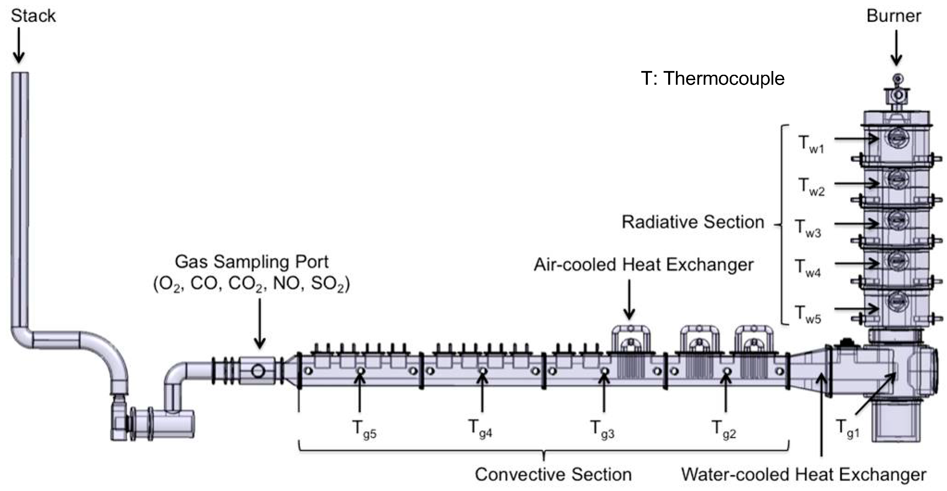
Figure 2 shows a schematic of the multi-fuel combustion system with a vertically down-fired furnace and a maximum thermal loading of 300-kWth [17]. The overall structure of the combustion system can be divided into three parts: radiative, convective, and flue gas sections. The vertical refractory-lined radiant chamber in the furnace has an inner diameter of 0.56 m and a length of 3.05 m and can be supplied with various types of fuel, such as diesel, HFO, emulsion fuel, pulverized coal, solid/liquid biofuel, etc. The radiative section (the vertical combustion chamber) is composed of 5 sub-sections, each of which is equipped with an R-type thermocouple to measure the wall temperature of the chamber, and an observation window to facilitate observation of the flame appearance and combustion stability. The set of two burners for burning solid and liquid fuels installed on top of the vertical furnace were designed and manufactured by C&C Engineering, Inc. (Taipei, Taiwan), with each one having a maximum thermal loading of 300-kWth. Both burners are equipped with a pilot flame, flame detector and pressure gauge for igniting the flame and monitoring its behavior.
In the present study, the vertical combustion chamber was utilized to conduct the experiments. Diesel alone and FPBO/diesel blends with 5 vol % FPBO were used as the fuels. A low-pressure air-assisted atomizer was employed for oil atomization [17]. The fuel stream was injected from the center of the nozzle with primary air (atomizing air), and the annular secondary air stream (combustion air) was injected into the combustion chamber. The primary air used to atomize the oil in the spray nozzle was kept at a constant value throughout the experiments. The secondary air was introduced by the tangential injection in a circumferential direction, thereby establishing a swirling-flow field in the centerline. The tubular oil spray flame was initially ignited by a pilot flame of liquid petroleum gas, which in turn led to a stabilized spray flame in the combustion chamber.
In the horizontal convective section, both water-cooled and air-cooled heat exchangers were installed to remove heat from the high-temperature flue gas. The flue gas zone was located next to the convective section. Prior to the stack, there was a 11.2 kW induced-draft fan, which was employed to remove the flue gas from the furnace and force the flue gas out through the stack. The induced draft fan could also be used to adjust the operating pressure.
2.3. Experimental Procedure
The combustion experiments were conducted using the vertical furnace, as shown schematically in Figure 2. Three experimental processes were carried out. Firstly, diesel was used as the fuel in the preheating procedure, which took around 22 h to ensure that every sub-section of the vertical furnace had reached a steady temperature distribution. After the pre-heating process, the diesel fuel was switched to the test fuels (diesel alone and the FPBO/diesel blends with 5 vol % FPBO) to perform combustion tuning. Finally, the optimum operating conditions (which met the minimum residual oxygen in the flue gas required for complete combustion) obtained from the combustion-tuning procedures were adopted for the stable combustion experiments.
The measurement configuration of the test furnace is shown in Figure 2. The wall temperatures and gas temperatures were measured with R-type and K-type thermocouples, respectively. More specifically, five R-type thermocouples (Tw1 to Tw5) were placed from top to bottom in the radiative section to measure the wall temperature of each section in the vertical furnace. Meanwhile, five K-type thermocouples (Tg1 to Tg5) placed from upstream to downstream were employed to measure the gas temperatures at various positions along the convective section. Moreover, Fuji Electric Analytical Analyzers (Fuji Electric Co., Ltd., Tokyo, Japan) were employed to analyze the flue-gas emissions, including O2, CO, CO2, NO, and SO2. The gas samples were conditioned using a flue-gas sample conditioning system through cooling, drying, and filtering before entering the analyzers. Thus, the emissions were expressed as a volume concentration on a dry basis in this study.
2.4. Furnace Preheating Process
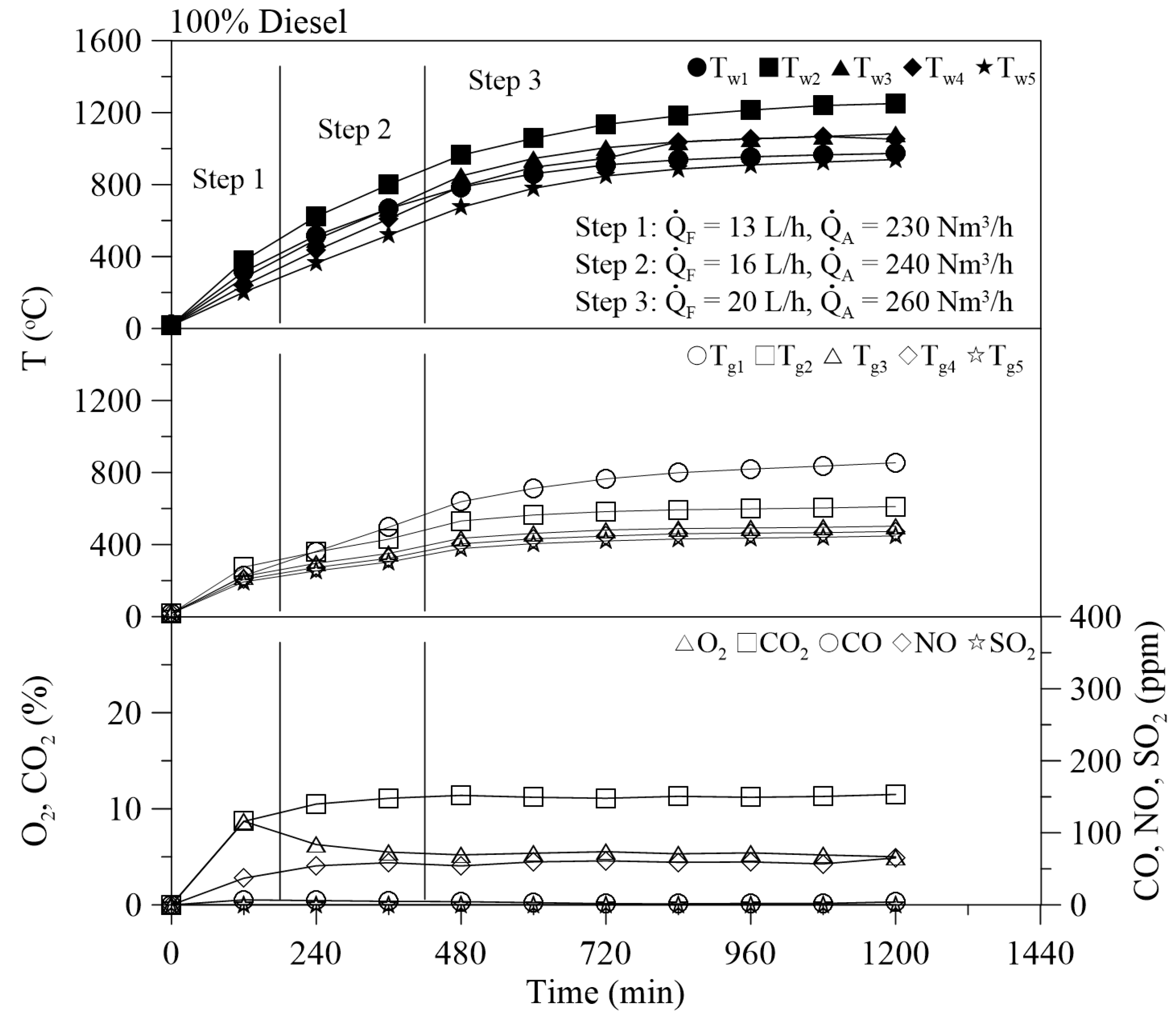
The combustion test furnace facility is lined with refractory bricks, which acts as a source of heat absorption. In order to avoid the influence of temperature variations on the combustion characteristics, it is necessary to provide a steady-state high-temperature environment. Accordingly, the furnace must be heated first until the wall temperature reaches a quasi-steady state before doing subsequent experiments. Diesel was employed as the fuel to preheat the furnace. The preheating process was performed step by step. Initially, during Step 1, a diesel flow rate of 13 L/h and an airflow rate of 230 Nm3/h were fixed for 3 h of burning. Secondly, during Step 2, the diesel flow rate was increased to 16 L/h, with an airflow rate of 240 Nm3/h for another 4 h of burning. Finally, during Step 3, the diesel flow rate was maintained at 20 L/h with an airflow rate of 260 Nm3/h for the last preheating period until the wall temperature did not change substantially over time, indicating the achievement of a quasi-steady state. As shown in Figure 3, all measured temperatures increased with time. After a long burning period (about 16 h), the temperature change was small. The preheating process took around 20 h to ensure that every sub-section of the vertical furnace had reached a steady temperature distribution. Meanwhile, the gas temperatures (Tg1–Tg5) in the horizontal convective section were nearly constant. Figure 3 also shows the variations in the emission composition of the flue gas in the exhaust with time during the preheating process. As can be seen, nearly constant concentrations of O2, CO, CO2, NO, and SO2 emissions were obtained after 8 h. The preheating process took about 20 h prior to conducting the combustion tuning and stable complete-combustion experiments.
After completing the preheating process, the next step was combustion tuning. The purpose of combustion tuning was to reduce the airflow rate to achieve the minimum residual oxygen in the flue exhaust required for complete combustion of the fuel. In both cases (diesel alone and the FPBO/diesel blend with 5 vol % FPBO) during combustion tuning, stable combustion was maintained for at least thirty minutes before taking data.
3. Results and Discussion
3.1. Combustion Tuning
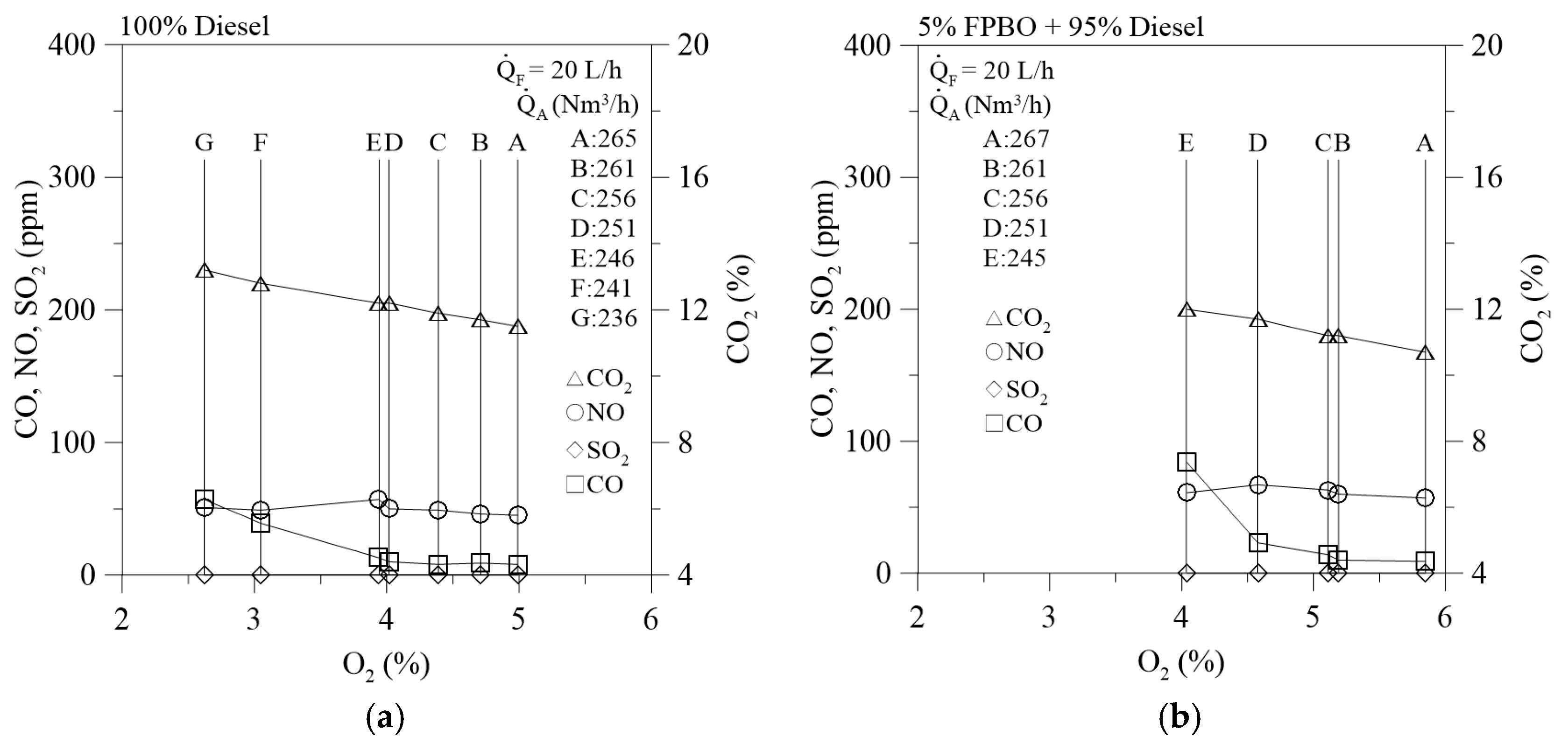
During combustion, the carbon content of the fuel burns in oxygen to form carbon dioxide. When oxygen appears in the flue exhaust, this indicates that more combustion air (excess air or excess oxygen) was supplied than was needed for complete combustion. However, when a supply of combustion air is inadequate, the fuel cannot get enough oxygen to burn completely, and incomplete combustion occurs, leading to CO formation. When the excess oxygen is reduced below a critical excess oxygen amount (critical point, e.g., point E in Figure 4a), CO formation increases rapidly. Therefore, to achieve a complete combustion situation, the excess oxygen amount must be adjusted above this critical point, below which incomplete combustion occurs, and CO increases significantly, leading to possible smoke generation because the amount of excess oxygen is too low.
Figure 4a,b show the variations in the emissions with residual oxygen measured in the flue exhaust during the combustion tuning process for burning pure diesel and the blend (5% FPBO + 95% diesel), respectively. The fuel flow rate () was fixed at 20 L/h in both the combustion tuning and stable combustion processes. Therefore, to determine the minimum oxygen required for complete combustion, the airflow rate was gradually adjusted from high to low levels, but the was maintained a constant value of 20 L/h. As shown in Figure 4a, points A, B, C, D, E, F, and G correspond to the airflow rates () of 265, 261, 256, 251, 246, 241, and 236 Nm3/h, respectively. The residual oxygen concentration decreased with decreases in the airflow rate from point A (265 Nm3/h) to point G (236 Nm3/h). For the airflow rate greater than the critical point (point E, 246 Nm3/h) for complete combustion, the CO emission was nearly 0 ppm. However, when the air flow rate was smaller than the critical point, the CO emission increased gradually, and consequently, a large amount of CO was generated, e.g., at point F and point G. Increases in the amount of combustion air corresponding to increases in excess oxygen thus in turn led to increases in the residual oxygen concentration. NO formation was found to increase with increases in the amount of excess oxygen from point G to point E, and then NO emission was nearly maintained at a slightly lower level from point D to point A. Formation of SO2 is directly related to the sulfur content of the fuel. Thus, when burning the same fuel, the SO2 emissions remain nearly at a constant value. A better adjustment of combustion air was found to at point E. With an airflow rate of 246 Nm3/h, both CO and NO emissions were low. Therefore, point E was taken as the optimum air-supply rate for the minimum excess-oxygen requirement with low CO emission and flue-gas heat loss. This operating condition was adopted for the subsequent stable complete-combustion diesel experiment.
Similarly, for the blend of 5% FPBO + 95% diesel, point C ( = 256 Nm3/h) was the optimum operating condition (which met the minimum residual oxygen in the flue gas required for complete combustion) obtained from the combustion-tuning procedures, as shown in Figure 4b. This optimum operating condition was also adopted for the subsequent stable complete-combustion experiment.
From the results of Figure 4a,b, the air-feed rates for the minimum excess-oxygen requirements were 246 and 256 Nm3/h for diesel alone and the blend of 5% FPBO + 95% diesel, respectively. That is, the airflow rate of the blend of 5% FPBO + 95% diesel at the critical point was slightly greater than that of diesel alone. More specifically, the theoretical air-to-fuel ratios (A/F ratios) for diesel and FPBO are 14.44 and 3.06, respectively, whereas the theoretical A/F ratio for the bio-oil/diesel blend with 5 vol % bio-oil is 13.67. The experimental A/F ratios for diesel alone and the bio-oil/diesel blend with 5 vol % bio-oil are 19.04 and 19.44, respectively. These experimental A/F ratios correspond to 31.85% and 42.2% excess air for diesel alone and the bio-oil/diesel blends with 5 vol % bio-oil, respectively. This indicates that the amount of excess oxygen for burning diesel alone is smaller than that for burning the blend. It was verified that the residual oxygen concentration (3.9%) in the flue gas for burning diesel alone is smaller than that (5.2%) for burning the blend, as shown in Figure 4.
3.2. Temperature Distribution
During the stable complete-combustion process, data retrieval was conducted once every 15 min by recording the temperatures in the radiative and convective sections of the furnace and the emission concentrations in the flue gas. Combustion instability did not occur in either case (diesel alone and the blend of 5% FPBO + 95% diesel). Figure 5a,b show the temperature distributions with time for the pure diesel (with an air flow rate of 246 Nm3/h) and the blend of 5% FPBO + 95% diesel (with an air flow rate of 256 Nm3/h), respectively, at a fixed amount of liquid fuel supply rate of 20 L/h. As shown in Figure 5a,b, due to the fact that the wall temperature of the combustion chamber had reached a near-steady state, the temperature change was very small during stable combustion under the optimum operating conditions (which met the minimum residual oxygen in the flue gas required for complete combustion). In other words, all the temperatures (Tw1–Tw5 and Tg1–Tg5) remained at almost constant values during the stable combustion processes.
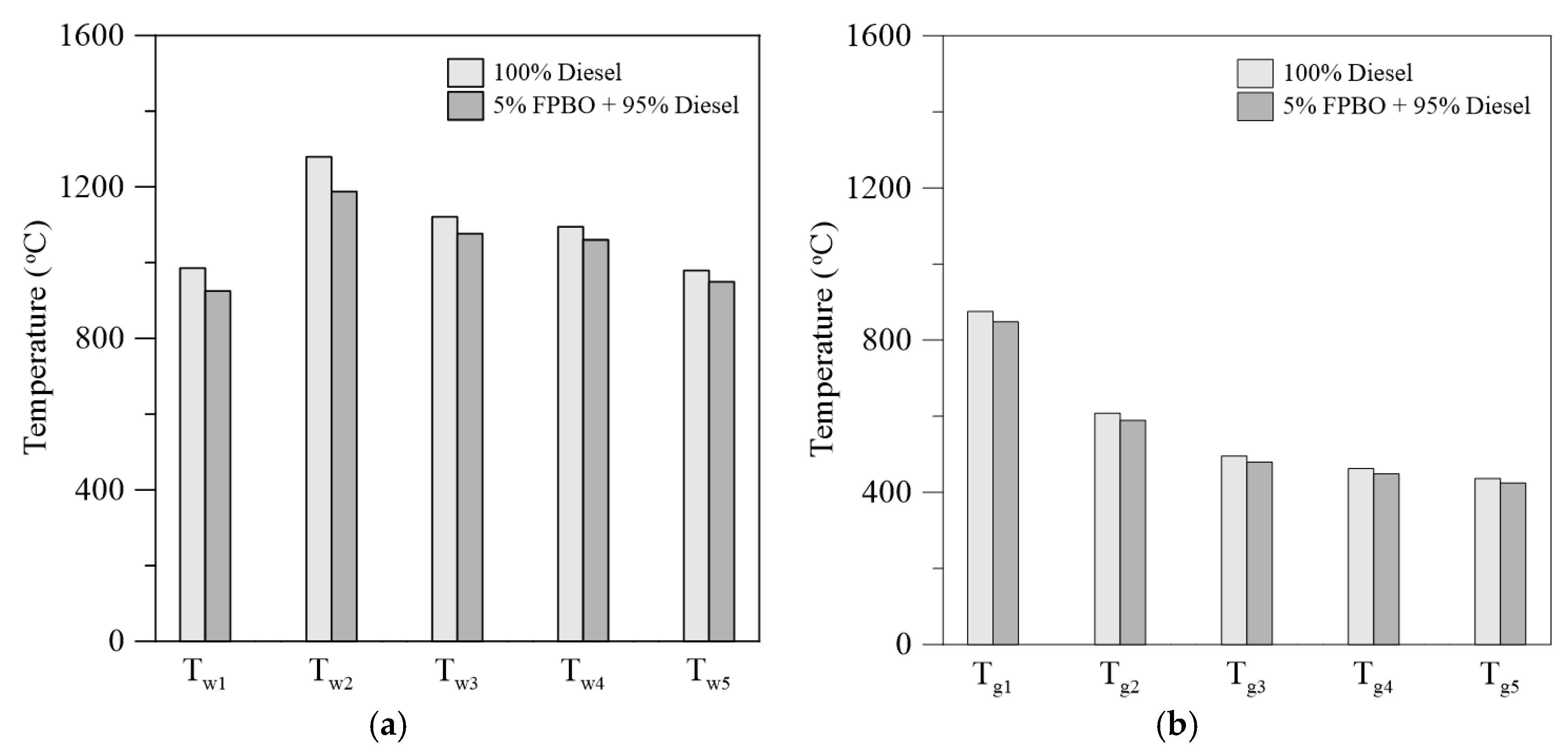
As shown in Table 3, the FPBO had a high oxygen content of 56.31 wt % and a smaller heating value (LHV: 14.41 MJ/kg) than the diesel fuel (LHV: 43.13 MJ/kg). Therefore, at a fixed fuel flow rate (20 L/h), the wall temperatures (Tw1–Tw5) in the radiative section and the gas temperatures (Tg1–Tg5) in the flue gas section dropped slightly when burning the blend of 5% FPBO + 95% diesel as compared with burning diesel alone, as illustrated in Figure 6a,b as well as Table 4. More specifically, in the primary combustion zone, when firing the blend of 5% FPBO + 95% diesel a lower Tw2 (1188.0 °C) was obtained as compared to when firing diesel alone (1279.2 °C). Figure 6b also demonstrates that the flue gas temperature decreased gradually from Tg1 to Tg5. This tendency is related to the measurement positions and the effects of cooling by using a heat exchanger.
3.3. Emissions
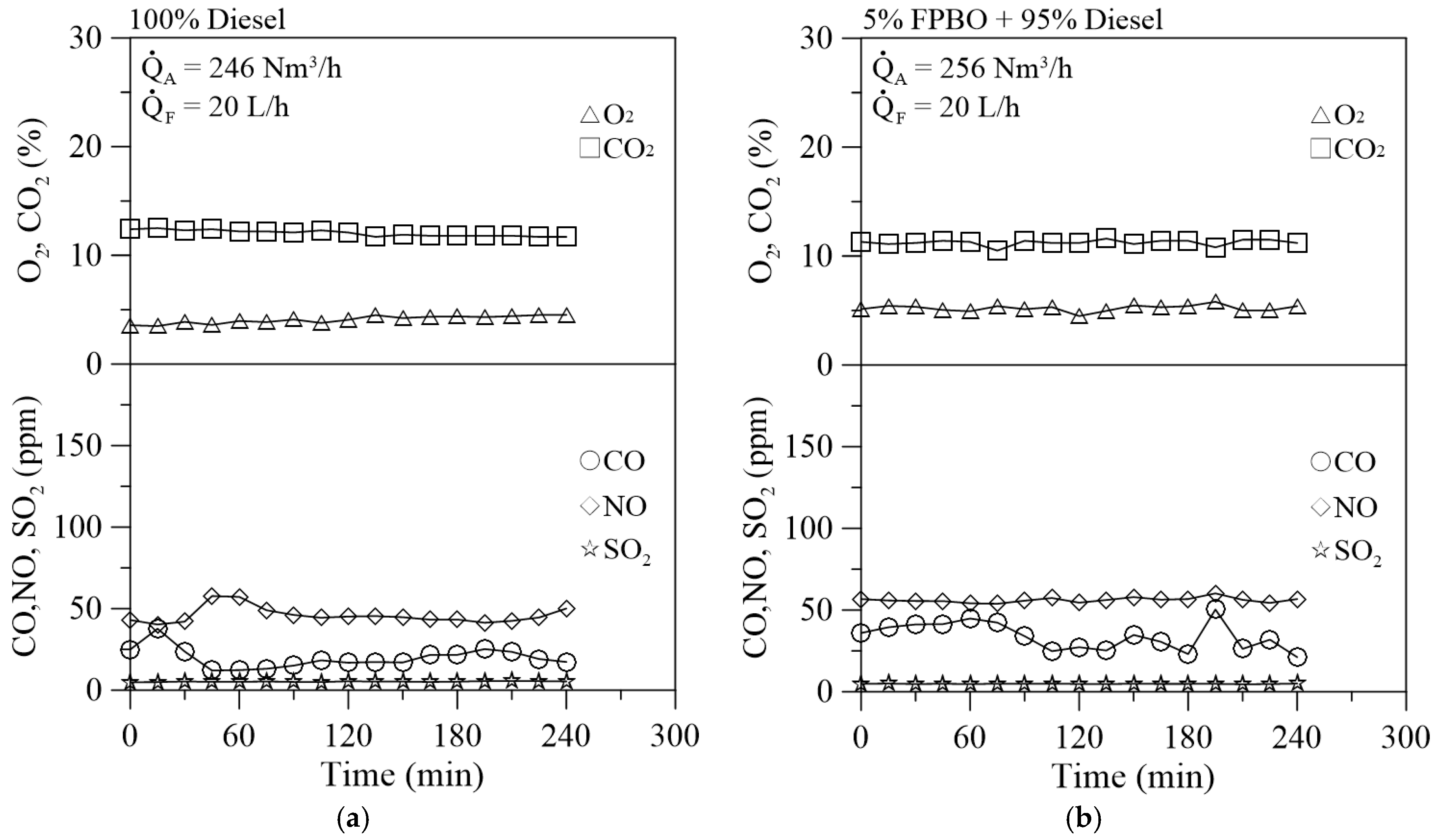
Figure 7a,b show the concentration of flue gas composition versus time for burning the pure diesel and the blend of 5% FPBO + 95% diesel, respectively, at a constant fuel supply rate of 20 L/h under the minimum residual oxygen in the flue exhaust required for complete combustion of the fuel. The values of CO, CO2, SO2 and NO reported in this study were all corrected to 6% O2 [17]. It was found that the variations in the O2 and CO2 concentrations with time for these two liquid fuels were very small. Figure 7 also indicates that the CO emissions for firing 5% FPBO have larger fluctuations than those for firing pure diesel. This may be due to the higher viscosity of FPBO than diesel. The higher viscosity of FPBO led to poorer atomization of the fuel spray, which linked to incomplete combustion (corresponding to higher CO emissions [16]) and larger fluctuations observed in the CO emissions.
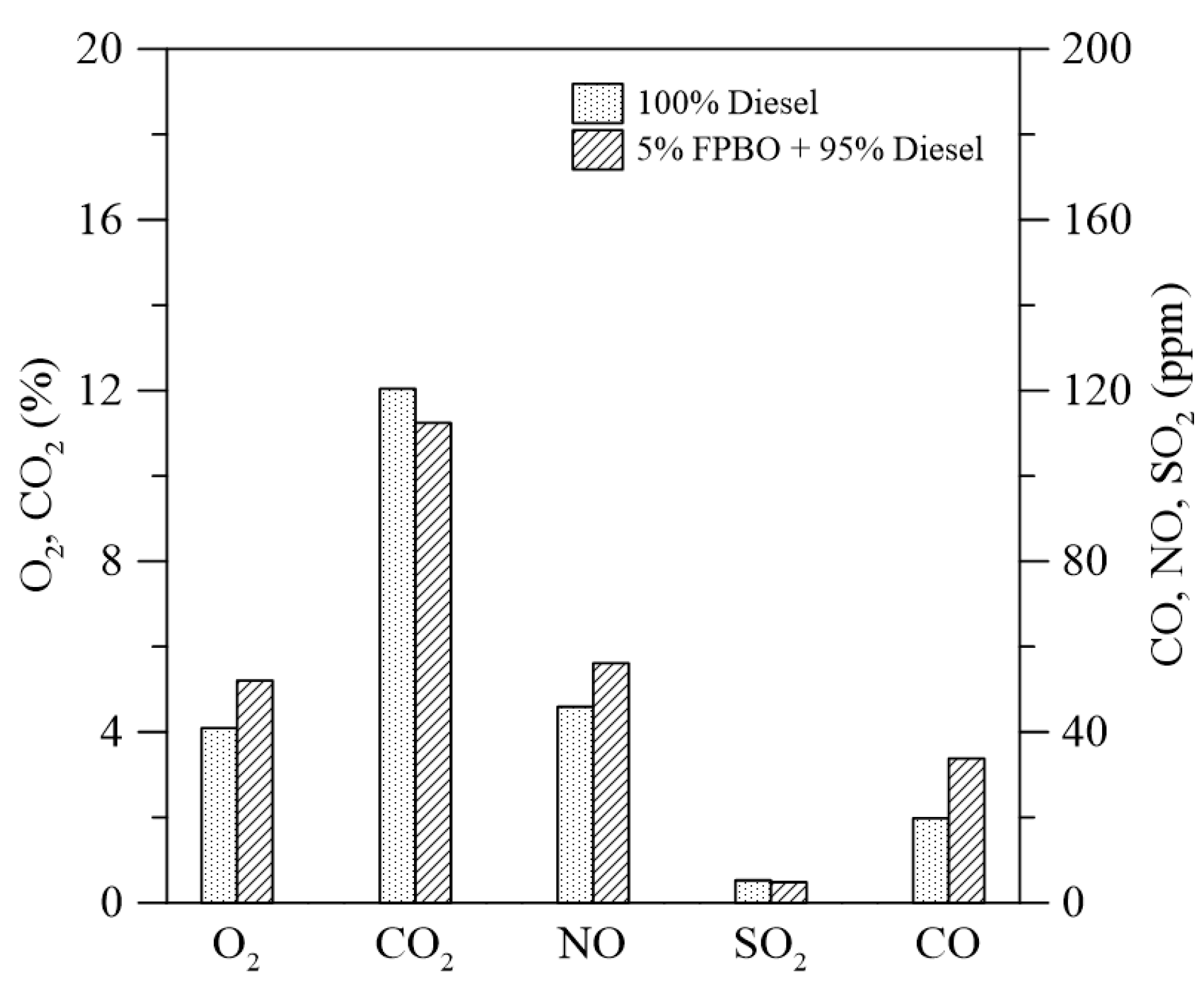
Figure 8 and Table 4 show that the average O2 concentration appearing in the flue exhaust for firing the blend of 5% FPBO + 95% diesel was 5.2%, while that for firing diesel alone was 4.1%. Meanwhile, the average CO2 emissions for firing the blend of 5% FPBO + 95% diesel and diesel alone were 11.2% and 12.0%, respectively, which were comparable.
Both firing cases were adjusted to meet the minimum excess oxygen conditions required for complete combustion. Consequently, the combustion was almost complete, resulting in low CO emissions (less than 35 ppm). The average CO emissions for firing the blend of 5% FPBO + 95% diesel and diesel alone were 20 and 34 ppm, respectively. Additionally, NO emissions were very low (smaller than 57 ppm) and were comparable for these two firing cases. It should be noted that when the wall temperature of a furnace reaches a near-steady state, the factor affecting NOX emission is only the gas temperature [31], not the wall temperature. Thus, the formation of nitrogen oxides has a clear dependence on excess oxygen, temperature in combustion and fuel-nitrogen (fuel-N). During firing, the blend of 5% FPBO + 95% diesel exhibited a lower temperature but higher excess oxygen (or higher residual O2 in the flue gas) and slightly higher fuel-N than was the case when firing diesel alone. The combined effects of temperature, excess oxygen and fuel-N resulted in slightly higher NOX emissions (56.1 ppm) for burning the blend as compared with burning diesel alone (45.9 ppm).
The amount of SO2 emissions significantly depends on the sulfur content in the fuel. Both FPBO and diesel have a very low sulfur content. As expected, the SO2 emissions for burning the blend of 5% FPBO + 95% diesel and the diesel alone were nearly zero.
In view of the emissions results, it can be summarized that the use of 5% FPBO in the blends produces comparable emission levels of CO, NO and SO2 when compared to pristine diesel.
3.4. Combustion Efficiency
According to the experimental results, the average CO concentration was maintained at a low-level (<35 ppm) in both cases. The combustion efficiency is defined as follows [16,32,33]:
where [CO2] is volume concentration on a dry basis of CO2, and [CO] is volume concentration on a dry basis of CO. Based on Equation (1), the combustion efficiencies could be obtained above 99.9% in this study. This revealed that excellent combustion efficiency was achieved.
4. Conclusions
In the present study, the combustion characteristics and pollutant emissions associated with firing fast pyrolysis bio-oil/diesel blends in a 300-kWth furnace were investigated. The following conclusions are drawn:
- (1)
- The air supply rates necessary to meet the minimum excess oxygen requirement were 246 and 256 Nm3/h, respectively, for pure diesel and the blend of 5% bio-oil + 95% diesel.
- (2)
- Combustion instability did not occur during the co-firing test without any modifications to the combustion system.
- (3)
- At a fixed fuel flow rate (20 L/h), burning the blend of 5% bio-oil + 95% diesel resulted in a slightly lower temperature in the combustion chamber than burning pure diesel, since the fast pyrolysis bio-oil has a lower calorific value and a high oxygen content of as much as 56.31 wt %. This indicates that similar furnace temperature distributions, and thus heating characteristics, were obtained during the co-firing test.
- (4)
- Compared with burning pure diesel, comparable NO emissions (smaller than 57 ppm) were obtained for burning the blend of 5% bio-oil + 95% diesel, and lower net CO2 emissions were achieved because biomass is both carbon neutral and renewable. Moreover, the CO concentrations under these two burning conditions were very low (less than 35 ppm) because of the minimum excess oxygen operating conditions required to achieve complete combustion.
- (5)
- The SO2 emissions for burning the blend of 5% bio-oil + 95% diesel and diesel alone were nearly zero (smaller than 6 ppm) since both the bio-oil and diesel have a low sulfur content.
This paper is the first report on the combustion characteristics and emitted pollutants of co-firing bio-oil produced from the fast pyrolysis process of coffee bean residue and diesel in a 300-kWth oil-fired furnace without any modifications to the system. It emphasizes the feasibility of using the blend as a substitute for diesel in industrial applications. Even though many interesting results are obtained, we realize that additional parametric studies are of significance and worth further study. For instance, the analysis of the effect of higher blend ratio, fuel pressure and atomizing-gas velocity on combustion characteristics and emissions is necessary. Furthermore, a study on reduction of PM (particulate matter) emissions is needed. These will be addressed in a separate study in the near future.
Acknowledgments
This work was supported by the Ministry of Science and Technology, Taiwan, under contract of MOST 105-3113-E-006-004.
Author Contributions
Wei-Cheng Huang performed the experiments and analyzed the results. Shuhn-Shyurng Hou generated ideas, designed experiments, analyzed the results, and wrote the manuscript. Ta-Hui Lin generated ideas, designed experiments, analyzed the results, and helped with editing the manuscript.
Conflicts of Interest
The authors declare no potential conflicts of interest with respect to the research, authorship, and/or publication of this article.
References
- Demrbaş, A. Fuel and combustion properties of bio-wastes. Energy Sources 2005, 27, 451–462. [Google Scholar] [CrossRef]
- Park, J.K.; Park, S.; Kim, M.; Ryu, C.; Baek, S.H.; Kim, Y.J.; Lim, H.H.; Park, H.Y. CFD analysis of combustion characteristics for fuel switching to bioliquid in oil-fired power plant. Fuel 2015, 159, 324–333. [Google Scholar] [CrossRef]
- Hassan, E.B.; Abou-Yousef, H.; Steele, P.; El-Giar, E. Characterization of bio-oils from the fast pyrolysis of white oak and sweetgum. Energy Sources Part A 2016, 38, 43–50. [Google Scholar] [CrossRef]
- Bridgwater, A.V. Review of fast pyrolysis of biomass and product upgrading. Biomass Bioenergy 2012, 38, 68–94. [Google Scholar] [CrossRef]
- Bridgwater, A.V.; Meier, D.; Radlein, D. An overview of fast pyrolysis of biomass. Org. Geochem. 1999, 30, 1479–1493. [Google Scholar] [CrossRef]
- Goyal, H.B.; Seal, D.; Saxena, R.C. Bio-fuels from thermochemical conversion of renewable resources: A review. Renew. Sustain. Energy Rev. 2008, 12, 504–517. [Google Scholar] [CrossRef]
- Chiaramonti, D.; Oasmaa, A.; Solantausta, Y. Power generation using fast pyrolysis liquids from biomass. Renew. Sustain. Energy Rev. 2007, 11, 1056–1086. [Google Scholar] [CrossRef]
- Brammer, J.G.; Lauer, M.; Bridgwater, A.V. Opportunities for biomass-derived “bio-oil” in European heat and power markets. Energy Policy 2006, 34, 2871–2880. [Google Scholar] [CrossRef]
- Zheng, J.L.; Kong, Y.P. Spray combustion properties of fast pyrolysis bio-oil produced from rice husk. Energy Convers. Manag. 2010, 51, 182–188. [Google Scholar] [CrossRef]
- Laesecke, J.; Ellis, N.; Kirchen, P. Production, analysis and combustion characterization of biomass fast pyrolysis oil–Biodiesel blends for use in diesel engines. Fuel 2017, 199, 346–357. [Google Scholar] [CrossRef]
- Ghanbari, M.; Najafi, G.; Ghobadian, B.; Yusaf, T.; Carlucci, A.P.; Kiani, M.K.D. Performance and emission characteristics of a CI engine using nano particles additives in biodiesel-diesel blends and modeling with GP approach. Fuel 2017, 202, 699–716. [Google Scholar] [CrossRef]
- Ge, J.C.; Yoon, S.K.; Kim, M.S.; Choi, N.J. Application of canola oil biodiesel/diesel blends in a common rail diesel engine. Appl. Sci. 2016, 7, 34. [Google Scholar] [CrossRef]
- Tamilselvan, P.; Nallusamy, N.; Rajkumar, S.A. comprehensive review on performance, combustion and emission characteristics of biodiesel fuelled diesel engines. Renew. Sustain. Energy Rev. 2017, 79, 1134–1159. [Google Scholar] [CrossRef]
- Elsanusi, O.A.; Roy, M.M.; Sidhu, M.S. Experimental investigation on a diesel engine fueled by diesel-biodiesel blends and their emulsions at various engine operating conditions. Appl. Energy 2017, 203, 582–593. [Google Scholar] [CrossRef]
- Yang, S.I.; Hsu, T.C.; Wu, C.Y.; Chen, K.H.; Hsu, Y.L.; Li, Y.H. Application of biomass fast pyrolysis part II: The effects that bio-pyrolysis oil has on the performance of diesel engines. Energy 2014, 66, 172–180. [Google Scholar] [CrossRef]
- Hou, S.S.; Huang, W.C.; Rizal, F.M.; Lin, T.H. Co-Firing of fast pyrolysis bio-oil and heavy fuel oil in a 300-kWth furnace. Appl. Sci. 2016, 6, 326. [Google Scholar] [CrossRef]
- Huang, W.C.; Hou, S.S.; Lin, T.H. Combustion characteristics of a 300 kWth oil-fired furnace using castor oil/diesel blended fuels. Fuel 2017, 208, 71–81. [Google Scholar] [CrossRef]
- Zeb, H.; Park, J.; Riaz, A.; Ryu, C.; Kim, J. High-yield bio-oil production from macroalgae (Saccharina japonica) in supercritical ethanol and its combustion behavior. Chem. Eng. J. 2017, 327, 79–90. [Google Scholar] [CrossRef]
- Lee, S.W.; Herage, T.; Young, B. Emission reduction potential from the combustion of soy methyl ester fuel blended with petroleum distillate fuel. Fuel 2004, 83, 1607–1613. [Google Scholar] [CrossRef]
- Daho, T.; Vaitilingom, G.; Sanogo, O.; Ouiminga, S.K.; Zongo, A.S.; Piriou, B.; Koulidiati, J. Combustion of vegetable oils under optimized conditions of atomization and granulometry in a modified fuel oil burner. Fuel 2014, 118, 329–334. [Google Scholar] [CrossRef]
- Park, J.K.; Park, S.; Ryu, C.; Baek, S.H.; Kim, Y.J.; Park, H.Y. CFD analysis on bioliquid co-firing with heavy fuel oil in a 400 MWe power plant with a wall-firing boiler. Appl. Therm. Eng. 2017, 124, 1247–1256. [Google Scholar] [CrossRef]
- Raclavska, H.; Juchelkova, D.; Roubicek, V.; Matysek, D. Energy utilisation of biowaste—Sunflower-seed hulls for co-firing with coal. Fuel Process. Technol. 2011, 92, 13–20. [Google Scholar] [CrossRef]
- Hou, S.S.; Rizal, F.M.; Lin, T.H.; Yang, T.Y.; Wan, H.P. Microexplosion and ignition of droplets of fuel oil/bio-oil (derived from lauan wood) blends. Fuel 2013, 113, 31–42. [Google Scholar] [CrossRef]
- Zhang, M.; Wu, H. Stability of emulsion fuels prepared from fast pyrolysis bio-oil and glycerol. Fuel 2017, 206, 230–238. [Google Scholar] [CrossRef]
- Zhu, Z.; Toor, S.S.; Rosendahl, L.; Yu, D.H.; Chen, G.Y. Influence of alkali catalyst on product yield and properties via hydrothermal liquefaction of barley straw. Energy 2015, 80, 284–292. [Google Scholar] [CrossRef]
- Xu, C.B.; Lancaster, J. Conversion of secondary pulp/paper sludge powder to liquid oil products for energy recovery by direct liquefaction in hot-compressed water. Water Res. 2008, 42, 1571–1582. [Google Scholar] [CrossRef] [PubMed]
- Musatto, S.I.; Machado, E.M.S.; Martins, S.; Texeira, J.A. Production, composition and application of coffee and its industrial residues. Food Bioprocess Technol. 2011, 4, 661–672. [Google Scholar] [CrossRef] [Green Version]
- Bok, J.P.; Choi, H.S.; Choi, Y.S.; Park, H.C.; Kim, S.J. Fast pyrolysis of coffee grounds: Characteristics of product yields and biocrude oil quality. Energy 2012, 47, 17–24. [Google Scholar] [CrossRef]
- Yang, S.I.; Wu, M.S.; Wu, C.Y. Application of biomass fast pyrolysis part I: Pyrolysis characteristics and products. Energy 2014, 66, 162–171. [Google Scholar] [CrossRef]
- Teng, H.; Huang, T.S. Control of NOx emissions through combustion modifications for reheating furnaces in steel plants. Fuel 1996, 75, 149–156. [Google Scholar] [CrossRef]
- Griffin, W.C. Classification of surface-active agents by HLB. J. Cosmet. Sci. 1949, 1, 311–326. [Google Scholar]
- Wu, K.K.; Chang, Y.C.; Chen, C.H.; Chen, Y.D. High-efficiency combustion of natural gas with 21–30% oxygen-enriched air. Fuel 2010, 89, 2455–2462. [Google Scholar] [CrossRef]
- Zhou, W.; Jiang, J.; Duan, L; Hao, J. Evolution of submicrometer organic aerosols during a complete residential coal combustion process. Environ. Sci. Technol. 2016, 50, 7861–7869. [Google Scholar] [CrossRef] [PubMed]
Figure 1.
(a) Oily phase; (b) aqueous phase; and (c) emulsion of 5% FPBO + 95% diesel (FPBO = 50 vol % oily-phase oil + 50 vol % aqueous-phase oil). FPBO: fast pyrolysis bio-oil.
Figure 1.
(a) Oily phase; (b) aqueous phase; and (c) emulsion of 5% FPBO + 95% diesel (FPBO = 50 vol % oily-phase oil + 50 vol % aqueous-phase oil). FPBO: fast pyrolysis bio-oil.

Figure 2.
Schematic of the 300-kWth multi-fuel combustion system.

Figure 3.
Variations in wall temperature, gas temperature and emissions with burning time using diesel as the fuel during the preheating process.
Figure 3.
Variations in wall temperature, gas temperature and emissions with burning time using diesel as the fuel during the preheating process.

Figure 4.
Combustion tuning process for burning (a) diesel alone; and (b) the blend of 5% FPBO + 95% diesel. The optimal air flows are point E for diesel alone and point C for the blend.
Figure 4.
Combustion tuning process for burning (a) diesel alone; and (b) the blend of 5% FPBO + 95% diesel. The optimal air flows are point E for diesel alone and point C for the blend.

Figure 5.
Temperature distributions with time for burning (a) diesel alone; and (b) the blend of 5% FPBO + 95% diesel.
Figure 5.
Temperature distributions with time for burning (a) diesel alone; and (b) the blend of 5% FPBO + 95% diesel.

Figure 6.
Comparison of average temperatures for burning diesel alone and the blend of 5% FPBO + 95% diesel: (a) the wall temperatures (Tw1–Tw5) in the radiative section; and (b) gas temperatures (Tg1–Tg5) in the flue gas section.
Figure 6.
Comparison of average temperatures for burning diesel alone and the blend of 5% FPBO + 95% diesel: (a) the wall temperatures (Tw1–Tw5) in the radiative section; and (b) gas temperatures (Tg1–Tg5) in the flue gas section.

Figure 7.
Emissions versus time: (a) when burning diesel alone; and (b) when burning the blend of 5% FPBO + 95% diesel.
Figure 7.
Emissions versus time: (a) when burning diesel alone; and (b) when burning the blend of 5% FPBO + 95% diesel.

Figure 8.
Average emissions when burning diesel alone and the blend of 5% FPBO + 95% diesel.


Table 1.
Properties of the oily phase and aqueous phase of FPBO (Fast pyrolysis bio-oil).
| Element Analysis | Oily Phase | Aqueous Phase |
|---|---|---|
| Carbon (wt %) | 42.56 | 23.54 |
| Hydrogen (wt %) | 4.32 | 5.41 |
| Nitrogen (wt %) | 0.62 | 0.77 |
| Oxygen (wt %) | 46.19 | 66.31 |
| Water content (wt %) | 22.0 | 87.0 |
| pH | 3.6 | 3.6 |
| Viscosity@40 °C (cP) | 221.0 | 0.75 |
| Lower heating value (LHV) (MJ/Kg) | 21.59 | 8.32 |
Table 2.
List of GC-MS (Gas Chromatography-Mass Spectrometry) area percentages of compounds in oily phase and aqueous phase (Reproduced with permission from [29], Elsevier, 2014).
Table 2.
List of GC-MS (Gas Chromatography-Mass Spectrometry) area percentages of compounds in oily phase and aqueous phase (Reproduced with permission from [29], Elsevier, 2014).
| Peak No. | (min) | Component | Area (%) | |
|---|---|---|---|---|
| Oily Phase | Aqueous Phase | |||
| 1 | 1.3 | Water | 0.61 | 15.29 |
| 2 | 1.6 | Acetone | 0.14 | 0.99 |
| 3 | 1.8 | Hydroxy-acetaldehyde | 0.08 | 0.27 |
| 4 | 1.9 | Acetic acid | 0.16 | 2.10 |
| 5 | 2.6 | 1-Hydroxy-2-propanone | 0.16 | 1.72 |
| 6 | 3 | Propionic acid | 0.21 | 0.64 |
| 7 | 3.9 | Pyridine | 0.11 | 0.24 |
| 8 | 4.6 | 1-Hydroxy-2-butanone | 0.06 | 0.17 |
| 9 | 5 | 2-Hydroxytetrahydrofuran | 0.05 | 0.13 |
| 10 | 5.2 | Cyclopentanone | 0.06 | 0.16 |
| 11 | 5.4 | Butyric acid | 0.08 | 0.17 |
| 12 | 6.3 | 2-Cyclopenten-1-one | 0.05 | 0.24 |
| 13 | 6.8 | Furfuryl alcohol | 0.23 | 0.88 |
| 14 | 7.7 | Butyrolactone | 0.24 | 0.71 |
| 15 | 8.4 | 3-Methyl-2-cyclopenten-1-one | 0.17 | 0.32 |
| 16 | 8.7 | Phenol | 0.52 | 0.53 |
| 17 | 9.2 | 2-Hydroxy-3-methyl-2-cyclopenten-1-one | 0.34 | 0.72 |
| 18 | 9.3 | 2,3-Dimethyl-2-cyclopenten-1-one | 0.21 | 0.33 |
| 19 | 9.4 | Cresol | 0.38 | 0.37 |
| 20 | 9.8 | 2-Methoxyphenol | 1.05 | 1.78 |
| 21 | 10.8 | Pyrocatechol | 1.52 | 2.32 |
| 22 | 11.3 | Hydroquinone | 0.35 | 0.47 |
| 23 | 11.5 | Methyl benzenediol | 0.92 | 1.07 |
| 24 | 11.9 | 2,6-Dimethoxy-phenol | 0.42 | 0.44 |
| 25 | 12.5 | Levoglucosan | 0.39 | 0.61 |
| 26 | 15 | Caffeine | 1.51 | 1.57 |
| 27 | 15.1 | Hexadecanenitrile | 0.85 | 0.33 |
| 28 | 15.4 | Palmitic acid | 6.22 | 0.42 |
| 29 | 16.2 | Linoleic acid | 1.63 | 0.22 |
| 30 | 16.4 | Stearic acid | 1.66 | 0.29 |
Table 3.
Properties of diesel, FPBO (50 vol % oily-phase oil + 50 vol % aqueous-phase oil), and the emulsion of 5% FPBO + 95% diesel.
Table 3.
Properties of diesel, FPBO (50 vol % oily-phase oil + 50 vol % aqueous-phase oil), and the emulsion of 5% FPBO + 95% diesel.
| Properties | Diesel | FPBO | 5% FPBO + 95% Diesel |
|---|---|---|---|
| Density (@20 °C) | 1.15 g/cm3 | 0.849 g/cm3 | |
| Density (@15 °C) | 0.8334 g/cm3 | ||
| Flash point | 74 oC | 79 °C | 75 °C |
| Pour point | −9 °C | −8 °C | −9 °C |
| Boiling point | 85–90 °C | ||
| Pyrolysis solids content | 1.15 wt % | ||
| Kinematic viscosity (@40 °C) | 2.763 cSt | 48 cSt | 4.98 cSt |
| Water content | 0.0 wt % | 54.5 wt % | 3.69 wt % |
| Water and sediment | 0.005 vol % | ||
| Ash content | 0.0 wt % | 1.21 wt % | 0.083 wt % |
| Carbon | 85.41 wt % | 33.05 wt % | 81.86 wt % |
| Hydrogen | 13.58 wt % | 4.87 wt % | 12.99 wt % |
| Oxygen | 0 wt % | 56.31 wt % | 3.81 wt % |
| Nitrogen | 0.45 wt % | 0.695 wt % | 0.47 wt % |
| Sulfur | 5.5 ppmw | 0.11 wt % | 0.008 wt % |
| Carbon residue | 0.08 wt % | ||
| pH | 3.6 | ||
| Lower heating value (LHV) | 43.13 MJ/kg | 14.41 MJ/kg | 41.19 MJ/kg |
| Higher heating value (HHV) | 46.01 MJ/kg | 16.40 MJ/kg | 44.00 MJ/kg |
Table 4.
Variations in average temperature distribution and gas emissions for diesel alone and the blend of 5% FPBO + 95% diesel under stable combustion conditions.
Table 4.
Variations in average temperature distribution and gas emissions for diesel alone and the blend of 5% FPBO + 95% diesel under stable combustion conditions.
| Fuel | 100% Diesel | 5% FPBO + 95% Diesel |
|---|---|---|
| Tw1 (°C) | 985.6 | 925.1 |
| Tw2 (°C) | 1279.2 | 1188.0 |
| Tw3 (°C) | 1120.9 | 1076.5 |
| Tw4 (°C) | 1094.8 | 1060.2 |
| Tw5 (°C) | 979.2 | 949.2 |
| Tg1 (°C) | 875.7 | 848.1 |
| Tg2 (°C) | 607.9 | 589.1 |
| Tg3 (°C) | 495.5 | 479.6 |
| Tg4 (°C) | 462.4 | 448.7 |
| Tg5 (°C) | 436.4 | 424.1 |
| O2 (%) | 4.1 | 5.2 |
| CO (ppm) | 20 | 34 |
| CO2 (%) | 12.0 | 11.2 |
| NO (ppm) | 45.9 | 56.1 |
| SO2 (ppm) | 5.2 | 4.9 |
© 2017 by the authors. Licensee MDPI, Basel, Switzerland. This article is an open access article distributed under the terms and conditions of the Creative Commons Attribution (CC BY) license (http://creativecommons.org/licenses/by/4.0/).
Share and Cite
MDPI and ACS Style
Hou, S.-S.; Huang, W.-C.; Lin, T.-H. Co-Combustion of Fast Pyrolysis Bio-Oil Derived from Coffee Bean Residue and Diesel in an Oil-Fired Furnace. Appl. Sci. 2017, 7, 1085. https://doi.org/10.3390/app7101085
AMA Style
Hou S-S, Huang W-C, Lin T-H. Co-Combustion of Fast Pyrolysis Bio-Oil Derived from Coffee Bean Residue and Diesel in an Oil-Fired Furnace. Applied Sciences. 2017; 7(10):1085. https://doi.org/10.3390/app7101085
Chicago/Turabian StyleHou, Shuhn-Shyurng, Wei-Cheng Huang, and Ta-Hui Lin. 2017. "Co-Combustion of Fast Pyrolysis Bio-Oil Derived from Coffee Bean Residue and Diesel in an Oil-Fired Furnace" Applied Sciences 7, no. 10: 1085. https://doi.org/10.3390/app7101085
Note that from the first issue of 2016, this journal uses article numbers instead of page numbers. See further details here.