Road Friction Virtual Sensing: A Review of Estimation Techniques with Emphasis on Low Excitation Approaches


School of Mechanical, Aerospace, and Automotive Engineering, Coventry University, Coventry CV1 5FB, UK
*
Author to whom correspondence should be addressed.
†
These authors contributed equally to this work.
Appl. Sci. 2017, 7(12), 1230; https://doi.org/10.3390/app7121230
Submission received: 26 October 2017
/
Accepted: 24 November 2017
/
Published: 28 November 2017
Abstract
:In this paper, a review on road friction virtual sensing approaches is provided. In particular, this work attempts to address whether the road grip potential can be estimated accurately under regular driving conditions in which the vehicle responses remain within low longitudinal and lateral excitation levels. This review covers in detail the most relevant effect-based estimation methods; these are methods in which the road friction characteristics are inferred from the tyre responses: tyre slip, tyre vibration, and tyre noise. Slip-based approaches (longitudinal dynamics, lateral dynamics, and tyre self-alignment moment) are covered in the first part of the review, while low frequency and high frequency vibration-based works are presented in the following sections. Finally, a brief summary containing the main advantages and drawbacks derived from each estimation method and the future envisaged research lines are presented in the last sections of the paper.
1. Introduction
Tyre forces influence largely the chassis stability and manoeuvrability [1]. These forces are limited by the maximum friction that can be generated between the tyre carcass and the road surface, which is the result of complex phenomena on the rubber-road interface. According to [2], such phenomena comprise molecular adhesion and indentation between the road irregularities and the tyre rubber. Despite rigorous studies having been developed to understand such interactions, vehicle dynamics engineers often feel more comfortable reducing these analyses to the estimation of a normalised coefficient, often called road friction potential [3] or tyre-road friction coefficient (TRFC) [4,5].
The estimation of the road friction potential has been studied exhaustively during recent years [3,6,7,8,9,10,11]. Specifically, it is envisaged that the accurate determination of such a coefficient can contribute to improve the performance of current vehicle systems such as Anti-Lock Braking System (ABS), Traction Control System (TCS), or Electronic Stability Program (ESP) [12,13,14]. An important drawback remarked by several authors is that a high excitation level (e.g., an emergency braking manoeuvre) is necessary in order to obtain an accurate estimation of the road grip potential when traditional slip-based approaches are employed [15,16,17,18]. Nevertheless, as the previous systems are triggered when a significant excitation is present, the friction coefficient can be estimated during the system intervention [19,20] and the system thresholds can be readjusted in parallel.
With the development of modern Advanced Driver Assistance Systems (ADAS), new stricter requirements regarding the road friction estimation have arisen [21,22,23,24]. Novel functions such as Adaptive Cruise Control (ACC) [25], Autonomous Emergency Braking (AEB) [26] or drift-based lateral collision avoidance [22,27,28] require an accurate and timely estimation of the maximum road grip prior to the intervention of the system. Thus, the road grip potential needs to be continuously monitored during free-rolling, coast-down or gentle acceleration events to correct critical variables such as the minimum separation between vehicles depending on the available friction. Moreover, novel drift-based applications not only require an estimation of the maximum road grip potential, but also a more detailed characterisation of the tyre-road friction (e.g., force versus slip curve [3,27,29,30,31]).
Several approaches have been discussed in the literature to estimate the road grip potential. A first classification provided in [7] establishes a distinction between cause-based and effect-based approaches. While cause-based approaches focus on estimating the road grip potential from aspects such as the lubricant present at the road surface [32,33], effect-based approaches infer the road grip from the tyre responses (e.g., slip [34,35]). Despite the fact that the former approaches can provide an accurate estimation of the grip potential during free-rolling driving conditions, an important handicap of these is that a database and extensive training is required in order to achieve an accurate correlation between the monitored road property and the road grip potential [7]. Therefore, such approaches might present insufficient correlation [36] or extrapolation issues where situations not included in the training dataset are faced. Regarding effect-based approaches, tyre slip-based, tyre vibration-based and tyre noise-based works have been found in the literature.
A general trend exhibited by slip-based approaches is that a significant excitation level (up to 80–90% on low-mu conditions [16]) is required to provide an accurate estimation of the road grip potential [37]. Such excitation thresholds have been reduced during recent years employing tyre-self alignment-based estimation methods [9,38,39,40,41]. These approaches take advantage of the higher sensitivity exhibited by the tyre self-alignment torque to changes in the road friction coefficient. Still, a certain level of grip utilisation is required, which according to the literature ranges between 30% and 50%. For pure longitudinal conditions, some authors argue that a clear correlation can be established between the road friction potential and the tyre longitudinal stiffness [6,7,42,43,44], and therefore the maximum road grip can be estimated if the previous tyre parameter is inferred from the vehicle longitudinal dynamics. On the other hand, recent experiments demonstrate that the longitudinal stiffness or slip slope does not change significantly when different high and low mu rigid surfaces are tested [45]. Therefore, the slip slope approaches might approximate well for severe changes in the road friction (e.g., from dry asphalt to gravel), but fail to estimate mu-jumps on rigid surfaces (e.g., colgrip board jump to painted board [45]). This discussion is continued in the following sections.
The limitations exhibited by slip-based approaches (mainly the necessity of generating large slip values) have encouraged researchers to explore low frequency [46,47,48,49] and high frequency [4,5,50,51] vibration-based approaches. The main objective of these solutions is to achieve an accurate grip potential identification during regular driving conditions. The general trend of noise-based solutions lies in the acquisition and subsequent post-processing of the high-frequency noise emitted by the tyre-road interface. Then, a suitable feature vector is designed and a classifier is trained to estimate the grip potential when new samples are available. Classifiers to distinguish roads of different roughness [46] as well as wetness [49] are present in the literature.
For low frequency vibration-based approaches, a wide range of solutions have been adopted, among which the analysis of the influence of the road grip potential on the frequency response of the driveline or steering system stands out in the literature. In particular, some authors have indicated that the tyre longitudinal stiffness can be correlated with the resonance frequency of the transfer function relating tyre torque disturbances and wheel speed [4,50]. In addition, authors found an empirical correlation between the tyre longitudinal stiffness and the road grip potential following the same slip slope concept employed in preceding longitudinal slip-based approaches [7,44]. Thus, if the previous correlations are employed, the road friction potential can be estimated from the wheel speed frequency responses.
To sum up, a complete picture of the road friction estimation problem discussed in this review is provided in Figure 1. The analysis is limited to effect-based approaches as these have received greater interest during recent years due to their cost-effectiveness and robustness. For additional discussions on cause-based approaches [7] can be consulted. The rest of the paper is organised as follows.
In Section 2 relevant background regarding vehicle modelling and tyre friction is provided. Moreover, the section is completed with a brief discussion regarding the potential impact of an accurate estimation of the road grip potential on current vehicle systems and envisaged future ADAS systems. The paper continues with a comprehensive discussion on slip-based road friction recognition approaches in Section 3. As remarked previously, special emphasis is put on the excitation levels required to achieve an accurate estimation of the grip potential. The same line of discussion is followed when tyre vibration-based (high and low frequency) are considered in Section 4. Finally, a comprehensive summary of the different approaches presented in this work is provided in Section 5 and conclusions and future research steps are detailed in Section 6.
2. Background
In this section relevant background to understand the tyre friction estimation problem is provided. Due to space limitations, only a brief discussion is given here regarding vehicle modelling, road friction modelling and the impact of the road friction information on the performance of vehicle systems and novel ADAS functions.
2.1. Vehicle Modelling
The vehicle planar dynamics can be approximated by the so-called single-track vehicle model, Figure 2b. This model is often employed in vehicle dynamics virtual sensing due to its reduced complexity [3,52]. If force balance and moment equilibrium equations are taken, Equations (1)–(3) can be obtained.
The vehicle longitudinal and lateral velocities are denoted by and respectively, and the yaw rate by . The vehicle mass is m, the yaw inertia , the distances from the front and rear axles to the centre of gravity and respectively, and the angle steered by the front wheels . Finally, the longitudinal forces are denoted by and the lateral forces by , with . Once the vehicle planar motion states are determined, the tyre lateral slips () can be computed from expressions (4) and (5).
If the ISO convention is adopted, the tyre longitudinal slip () is obtained from the expression (6),
with , being the wheel rotational speed, and the effective radius [14]. Several slip conventions (e.g., ISO, PRAXIS) have been described in the literature. For simplicity, only the ISO convention is used here. For a more detailed discussion [53,54] can be consulted.
Finally, the wheel speed evolves according to the wheel rotating dynamics, expression (7),
In this case, is the total rotating inertia of the wheel and driveline assembly, is the driving torque, is the braking torque, is the rolling resistance, the tyre vertical force, and the loaded radius.
2.2. Road-Rubber Friction
In Section 4 a comprehensive review of friction estimation methods based on the tyre’s vibration/frequency response is presented. These are broadly distinguished in those that use low-frequency range features and high-frequency range ones. In order to facilitate the understanding of some of the concepts described in Section 4, a short discussion regarding the dependence of the tyre properties and forces on the temperature and stress frequency is introduced here.
2.2.1. Tyre Properties as a Function of Temperature and Stress Frequency
As mentioned previously, the friction generated in the road-rubber interface is the result of a set of complex interactions between the tyre and the road, which can be summarised by two stress mechanisms: road roughness effect and molecular adhesion [2]. Such effects arise from the viscoelastic properties of the tyre, which can be approximated by a spring K connected in parallel to a damper of damping coefficient [2], Figure 3a. Therefore, the force generated by the tyre can be expressed as a function of the deformation y, the rate of deformation , and the tyre properties.
Tyre properties are function of temperature, see Figure 3b. The tyre’s modulus of elasticity, represented by the spring K, is maximum below the glass transition temperature , and reduces for temperatures greater than that. The tyre’s damping mechanism, also known as hysteresis or energy loss, represented by is maximum at the glass transition temperature. For temperatures different to that, the energy loss is smaller. As a matter of fact, winter tyres are designed to have a lower glass transition temperature compared to summer tyres. Consequently, when only the tyre force between the tyre and the road is considered, winter tyres generate larger forces at low temperatures compared to summer tyres and summer tyres generate larger forces at increased temperatures [2].
Tyre properties are also a function of stress frequency, the frequency at which the load is applied, see Figure 4. At low excitation frequencies/velocity , the damper does not contribute much, therefore the influence of the spring K is dominant. The opposite happens at higher frequencies, where the damper becomes more important. Regarding the energy loss, this becomes maximum at an intermediate range of frequencies and falls for frequencies different to that. At low excitation frequencies, the energy loss is small because the damping mechanism is not important. At higher excitation frequencies there is not enough time for the tyre’s rubber molecules to return to equilibrium and thus rubber remains constantly in tension. Therefore, the tyre’s modulus of elasticity is low in the low excitation frequency range and high in the high-frequency excitation range. A careful observation reveals that maximum energy loss occurs when the modulus of elasticity changes.
Hence, to understand how a tyre behaves, the tyre type needs to be considered and the temperature and stress frequency monitored [55]. When temperature increases the material becomes softer (lower modulus of elasticity), while when stress frequency increases the material becomes more rigid (higher modulus of elasticity). Other parameters, such as the tyre inflation pressure, also influence the rigidity of the tyre [56], and therefore are expected to be monitored.
2.2.2. Tyre Friction Force as a Function of Stress Frequency
The friction force between the tyre and the road is generated as a result of the relative slippage between the elastomer and the road surface. If there is no relative slippage then there is no tyre force. Two stress mechanisms intervene during the generation of tyre forces: molecular adhesion and indentation.
- Molecular adhesion: The first mechanism is the adhesion [57]. The grip derived from the adhesion between the rubber and the road is the result of the Van der Waals bonding phenomena. The rubber’s molecular chains form, stretch and break, following a cycle of stretching and breaking, and generating visco-elastic work. This adhesion mechanism occurs in a range of stress frequencies between Hz and Hz, and requires the separation distance between the road and the rubber to be below mm [2]. The bonding phenomena can be explained in a simplified manner by three steps, Figure 5b. In the first step the bond is created. After that, in step 2, the molecular chain is stretched, and a friction force which opposes the tyre skidding is generated. Finally, in the last step, the bond breaks and new bonds form again successively.
- Road roughness effect: The road roughness effect (also denoted as indentation) is primarily caused by the road irregularities [58,59] and the hysteresis of the rubber [2]. The road texture (with rough spots that vary from 1 centimetre to 1 micron) induce a high-frequency excitation on the rubber (with frequencies ranging from to Hz [2]), which is distorted and undergoes several compression-relaxation cycles. As the rubber presents an inherent hysteresis, the rubber does not return immediately to its initial position, but exhibits an asymmetrical movement (and therefore an energy loss). Such asymmetrical movement of the rubber block around the rough spot results in a force field, with a tangential component which opposes the slippage and is seen as the tyre force [2].
The proportion in which each friction generation mechanism contributes to the total amount of grip available between the tyre and the road depends on the road irregularities and the road contamination, the latter factor having the highest influence. Regarding the road roughness, an analytical expression for the kinetic coefficient of friction has been proposed by Persson [60] as a sum of a set of hysteresis forces caused by the multiple scales of the road surface texture,
where q is the spatial angular frequency or magnitude of the wave vector corresponding to the wavelength , is the lower integration limit (where L depends on the length of a tread block), is the upper cut-off frequency, E is the complex viscoelastic modulus of the rubber, v is the sliding velocity, is rubber’s Poisson ratio, is the direction of the wave vector in relation to sliding and is the relative contact area. For dry friction, the short wavelength limit is 1 micrometre, as mentioned in previous works [61].
The function denotes the two-dimensional power spectral density (PSD) of the pavement surface:
where h(x) is the surface height measured from the average plane with and , and stands for ensemble averaging. The statistical properties of the texture are assumed to be isotropic so that only depends on the magnitude of the wave vector q. Typical examples of Power Spectral Densities (PSD) for different types of road surfaces, according to ISO 8608 [62], are shown in Figure 6.
In [2] it is remarked that while the road roughness presents little influence on the maximum friction potential in dry conditions, this changes drastically when third bodies are present on the rubber-road interface [61,64,65]. Examples include wet road surfaces, icy surfaces that melt under the application of braking force or dry particles deposited on the road surface (gravel). Depending on the micro or macroroughness of surfaces subjected to damp or wet conditions the road friction potential can rage from to . For example, in the case of wet road surfaces the tyre force due to adhesion, i.e., Van der Waals forces, is absent. Furthermore, the upper cut-off frequency is reduced depending on the amount of third bodies that need to be expelled and the macro and micro texture of the road surface [60].
According to [2], the highest friction values are observed on roads with microrough surface characteristics. The rough spots create individual high-pressure points that break-through the film of water present at the road-rubber interface. On the other hand, lowest values of friction potential (0.2–0.1) are observed on microsmooth wet surfaces, where neither the roughness nor the molecular adhesion mechanisms are generated appropriately, Table 1.
2.2.3. Tyre Models as a Function of the Friction Coefficient
Relevant models have been presented in the literature to infer the maximum road-rubber friction characteristics employing the surface profile and the rubber characteristics [60,66]. A brief introduction was provided in the previous paragraphs. In practice, such an analysis is not adopted in vehicle dynamics applications. Instead, the road-rubber friction is expressed as a function of the lateral (4) and (5) and longitudinal (6) slip quantities, which can be easily computed from standard vehicle on-board measurements. Thus, analytical (e.g., Brush model [67]), empirical (e.g., Magic Formula [67]) and data-based (e.g., Neural Networks [3,68]) friction models are constructed to calculate the friction forces derived from a certain combination of and values, expression (15).
The evolution of the road friction with the tyre slips is often portrayed (see Figure 7) assuming a fixed wheel inclination angle (), and tyre pressure (). The lateral or longitudinal slip value at which the maximum friction is located varies significantly with the road characteristics and the tyre tread. As a reference, low values are seen on competition tyres (high longitudinal and lateral tyre stiffness), and high values are obtained on loose surfaces (e.g., deep snow, gravel) [2,31,69,70,71]. The most extended friction models are the Magic Formula [67] presented by Hans B. Pacejka, the Dugoff [14,72] tyre model, and the Brush analytical formulation [16,17,67]. The Dugoff and Brush tyre models are often given preference in road friction recognition problems due to their implementation easiness and cost-effectiveness [53]. Other friction modelisations have been proposed in the literature (e.g., Burckhardt friction model or Lugre and Dahl dynamic tyre models) [73,74], but these are omitted in this section due to their reduced use in the reviewed works and their added complexity.
In the following section the Magic Formula, the Brush formulation, and the Dugoff model are introduced. For additional friction models and a more detailed discussion [53] can be consulted.
- Magic FormulaThe Magic Formula [67] consists of a nonlinear formulation based on arctan functions. The coefficients , with , are determined empirically, based on experimental data. A simplified Magic formula formulation is presented here [8,31]. More sophisticaped and complex formulations can be consulted in Hans B. Pacejka [67]. Firstly, the one-directional normalised tyre forces () are computed from expressions (16) and (17).After that, in order to handle combined efforts, the weighting functions () can be defined in the following manner [8]:Finally, the one-directional friction coefficients are obtained from the product of these weighting functions and the normalised forces calculated previously, expression (20).If load sensitivity effects are disregarded, the tyre planar forces can be obtained from the vertical forces as (), [8].
- Brush modelIn this formulation the pure longitudinal force is obtained from expressions (21)–(24). During gentle driving conditions, the tyre longitudinal slip keeps below the critical slip and the first expression is used. Under strong braking or acceleration events () the entire contact patch is sliding, and the second expression is used.In this case the normalised tyre forces are presented (), the tyre tread stiffness is denoted by , and the longitudinal slip at which the full-sliding condition starts is . The derivation of the friction model in the lateral direction is straightforward from expressions (25)–(28) [17].Once again, during gentle cornering, the lateral slip () remains far below the nonlinear region (), and the lateral friction is approximated by the first expression. Otherwise, during limit cornering and full sliding conditions, the second expression is used. Finally, the tyre self-alignment torque (SAT) can be calculated with the expression (29) [17].As occurs in the Magic Formula model, in the event of simultaneous efforts in the longitudinal and lateral directions, a resultant friction is calculated (30) based on the total slip [17].The resultant friction is then projected in the lateral and longitudinal directions assuming the slip-proportionality principle.
- Dugoff modelThe Dugoff model [75] derives from the research described in Fiala [76]. A uniform rectangular pressure distribution and a rigid tyre carcass are assumed in this model. In addition, conversely to the Brush model described previously, individual tread stiffnesses (, ) are considered. In first place, a coefficient is defined to account for the coupling between lateral and longitudinal forces, (38) [14,72].In the formulation presented here, the PRAXIS slip notation [54] is adopted, and the lateral () and longitudinal () slips are computed differently depending on the driving situation:
- −
- Driving:
- −
- Braking:
After that, the function is computed from the saturation level of the tyre, (41).Finally, longitudinal and lateral forces are obtained from expression (42) [14,72],and the road-rubber friction values () can be easily obtained if the longitudinal and lateral tyre forces are divided by the vertical force as , with . The application of these models to road friction estimation will be studied in Section 3, Slip-based road friction monitoring.
2.3. Vehicle Systems: The Role of Road Friction
As remarked by several authors, the knowledge of the road friction potential can contribute significantly to the enhancement of vehicle systems [14,15,23,36,37,77,78]. According to [23], the enhancement of vehicle systems can benefit largely the driver, and in an upper level, the society (e.g., improved traffic safety/accident prevention). The author provides a diagram where it is showed how the collection and distribution of road friction information can benefit several applications, Figure 8.
In particular, Koskinen [23] highlights that such applications can be summarised into driver information systems, vehicle dynamic control systems, Advanced Driver Assistance Systems (ADAS), and co-operative applications. In this subsection, the focus lies on discussing how the road friction estimation can enhance the performance of vehicle systems, and in particular, Advanced Driver Assistance Systems (ADAS). For additional discussion on the rest of applications, Koskinen [23] can be consulted.
In Figure 9 the influence of the road friction potential information on different vehicle systems is provided. Well-known chassis systems such as Anti-lock Braking System (ABS), Traction Control System (TCS), and Electronic Stability Program (ESP) are situated at the lowest level. Such systems already compute an estimation of the road friction potential to adjust their thresholds during high dynamic excitation. An accurate a priori knowledge of the road friction potential might enhance the performance of these systems during the beginning of the intervention (e.g., brake pressure modulation during the first cycles of the ABS), but apart from this, a significant improvement would not be seen [23]. On the other hand, current ADAS such as Autonomous Emergency Braking (AEB) [26] or Adaptive Cruise Control (ACC) [25] depend strongly on the road grip potential and therefore are situated in a higher level. These systems rely on an a priori knowledge of the road friction potential to compute the minimum separation distance (i.e., safety distance) between the ego and a preceding vehicle. A wrong assumption of the true road grip potential can lead to a severe collision or to a false unwanted intervention [77]. Moreover, in this case, the road grip potential must be estimated during regular driving conditions in which the lateral or longitudinal excitation is reduced (e.g., free-rolling driving). This complicates significantly the applicability of traditional slip-based approaches on the previous ADAS.
Finally, novel ADAS systems such as Autonomous Drift Control (ADC) [22,27,30], Figure 10, are situated at the highest level. This system has been proposed by the authors with the aim to maximise the vehicle cornering performance on loose surfaces of limited manoeuvrability (e.g., gravel, deep snow [29,31]) and is inspired by previous research works on automated drift control [29,79] and agile manoeuvring [80,81].
In particular, the most recent ADC system developed by the authors [30] coordinates individual wheel torque inputs from in-wheel electric motors [82,83,84,85,86] and the steering wheel angle from an Active Front Steering (AFS) system to stabilise the vehicle around large body slip angles. The first results indicate that the correct estimation of the road-friction characteristics has a large impact on the drift stabilisation. Moreover, in extreme off-road conditions the traditional grip scaling approach presented in [67] and commonly adopted in slip-based approaches [3,8] is not valid due to the severe distortion of the friction versus slip curve (the - curve presents a monotonic shape and a maximum friction slip is not distinguished, Figure 7). Thus, alternative approaches must be developed to identify online not only the maximum friction potential but also additional features of the surface-rubber interaction characteristics (e.g., evolution of the cornering stiffness along the slip curve [52]). Self-adaptive tyre models based on Adaptive Neuro-Fuzzy Inference Systems (ANFIS) are currently being investigated by the authors. Promising results have been presented in [27].
To summarise, while an accurate estimation of the road grip potential might not have a large impact on current chassis systems, such information is critical for current ADAS functions. In addition, authors envisage that an accurate estimation of the road friction characteristics will be extremely important for future autonomous vehicles.
3. Slip-Based Road Friction Monitoring
The estimation of the road friction potential from signals that are already available on the CAN bus of modern vehicles has been extensively investigated in the literature. The major common point of these strategies is that the friction potential is extracted from a rubber-road friction model such as described in Section 2.2.3. In brief, the tyre forces and the tyre slips are observed from the vehicle dynamics (e.g., using a state estimator) and employed in a friction model. The maximum friction potential is then inferred from the difference between the reconstructed forces and the forces provided by the model for the current tyre slip values.
Depending on the approach considered, the friction model can take the form of an analytical expression (e.g., Brush model [87,88]) or a Neural Networks structure [3,10,68]. The main drawback derived from this methodology is that a certain longitudinal or lateral slip is necessary in order to accomplish such estimation.
In Figure 11a the tyre longitudinal forces obtained from a parameterised Magic Formula 6.1 tyre model [3] are depicted. As can be noticed, the slope of these forces does not change significantly between high and low adherence rigid road surfaces (e.g., dry asphalt, wet asphalt) when the longitudinal excitation is kept low (i.e., negligible difference is observed between and for < ). This behaviour is derived from the infinitely rigid road assumption employed to formulate the Brush and Magic Formula tyre models [67]. As a consequence, the slope of the tyre forces is considered only a function of the tyre tread stiffness in these models, and is not affected by the coefficient. This has been evidenced experimentally under well-controlled braking tests performed in a wide range of rigid surfaces by Andrieux et al. [45]. Nevertheless, in a large number of works the previous statement is refuted and the so-called “slip slope” concept is presented. In particular, the slip slope idea states that the tyre longitudinal stiffness (slope on Figure 11a) presents significant variations between high and low adherence surfaces. In these works it is claimed that the slip slope tyre phenomena facilitate the estimation of the friction potential under minimum excitation levels using traditional slip-based approaches. As this approach is often tested on rigid as well as loose surfaces (e.g., snow, dry asphalt, ice, and gravel) the change in the slip slope might be induced by the soft material (e.g., sand) deposited between the tyre and the rigid road [17]. Moreover, the slip slope presents significant variations depending on external tyre parameters, such as the tyre pressure or the tyre wear [6,7]. As a certain degree of controversy exists around the slip slope idea, these results are considered in more detail in the following sections.
Leaving aside the slip slope discussion, this survey evidences that a non-negligible grip consumption level is always required to estimate the road friction potential. This limits the performance of slip-based strategies during free-rolling driving conditions. Some studies presented in this survey indicate grip consumption levels that range from 30% to 80 %. Lowest values are observed when tyre SAT-based approaches are employed due to the higher sensitivity of the former signal to variations in the lateral slip (i.e., earlier tyre SAT saturation, Figure 11b) [9,38] (See Section 3.3). In spite of these drawbacks, slip-based road friction monitoring is cost-effective and generally computationally inexpensive. Moreover, it can provide an accurate online estimation when enough excitation is present (e.g., during ABS or ESP intervention).
The main aim of this discussion is to provide some clarity regarding the minimum grip consumption thresholds required by the most relevant slip-based approaches existing in the literature. This will evidence the necessity of new approaches (e.g., tyre vibration-based) to estimate the maximum road grip during free-rolling conditions. Furthermore, this will facilitate the selection of the excitation thresholds required by future combined [17] or “friction fusion” strategies (e.g., vibration-based during coast down driving and slip-based during hard accelerations [12]). The next subsections follow the structure presented in Figure 12, and provide a comprehensive discussion on slip-based methods for longitudinal dynamics manoeuvres, lateral dynamics manoeuvres, and tyre self-alignment torque measurements. Due to space limitations, only the most relevant works in the opinion of the authors are discussed in detail. In addition, the analysis is restricted to the friction potential estimation. A comprehensive list of relevant tyre force estimation methods can be found in [53]. Finally, only real-time works are presented in this review. For further details on other offline approaches [52,89,90] can be consulted.
3.1. Longitudinal Dynamics
A large number of works have been presented to estimate the friction potential from the vehicle longitudinal dynamics (e.g., braking manoeuvres). These can be classified into longitudinal stiffness or slip slope-based approaches [6,7,17,44,91,92], friction model-based approaches [12,13,16,18,19,21,93,94,95] and active force excitation approaches [71,96]. Despite slip slope approaches belong to the friction model-based group (i.e., linear longitudinal stiffness tyre model), a distinction has been made to treat them in greater detail. Furthermore, a new promising approach recently developed by Albinsson et al. (active force excitation) has been added to the discussion.
Slip slope approaches are based on the assumption that the tyre longitudinal stiffness depends on the maximum road friction coefficient [6]. Therefore, provided that a suitable function is found, the friction estimation problem can be solved by monitoring the tyre longitudinal stiffness. In Gustafsson [6] a linearised friction model is presented to estimate the slip slope and the friction bias from the tyre longitudinal slip and the normalised longitudinal force (),
where the force is obtained from the measured engine torque and is calculated using the difference between the driven and non-driven wheel speeds. Different roads (asphalt, wet asphalt, gravel, snow and ice) and tyres (MXT, MXV2 (almost worn out), NCT2 and Eurofrost (winter tyres)) were tested, and a rule-based classifier was proposed based on the empirical results. Slip slope coefficients varied significantly depending on the tyre considered, and well-clustered surfaces were obtained only for the Eurofrost tyre. In addition, authors remarked that the values obtained in these tests were very sensitive to variations in tyre parameters such as the tyre pressure or the tyre tread depth (tyre wear). In Muller et al. [7] several braking manoeuvres were performed on dry () and soapy roads (). The tyre forces were measured from a strain-based torque sensor and the braking action was performed only at the front wheels. The slip slope was calculated using recursive least squares (RLS) on the model given by expression (43) and significant differences between the tested surfaces were obtained for grip consumption levels of . These tests were repeated employing a cost-effective experimental setup and the following slip slope ranges were found, Table 2:
Once again, the high variability of the slip slope coefficient was highlighted by the authors. Moreover, Muller et al. indicated that the relation that works at the present time might not work during the next month, thus remarking the strong dependence of this coefficient on tyre parameters such as inflation pressure or tyre wear. In Ahn [17] longitudinal stiffness values of a Pirelli 255/50R-17 installed in a Jaguar S-type are provided, Table 3. Additional details regarding the temperature at which the tests on ice were performed are not given. As will be seen in Section 4.1, some authors argue that the ice temperature can have a significant impact on the tyre longitudinal stiffness or slip slope factor.
A linear regression was performed to obtain these values setting the maximum longitudinal slip to . Ahn presents the “equivalent tyre-road stiffness” theory [42,53] to explain the differences seen on . Specifically, this theory attributes the variations in slip slope to the presence of soft material (e.g., gravel, snow or wet ice) in the road-rubber interface. Under these conditions, the surface can no longer be considered infinitely rigid with respect to the tyre carcass, as states the accepted tyre modelling theory [67].
In Rajamani et al. [44] the slip slope is estimated using RLS from the linear relationship
In addition, the authors proposed a linear expression to relate the slip slope to the road friction potential, , where A and C are constant parameters determined empirically. In particular, the authors found the previous coefficients from the slip slope estimates obtained in dry asphalt and gravel surfaces. In this case, the “equivalent tyre-road stiffness” theory holds, and the abrupt reduction of in gravel conditions correlates well with the experimental tyre model parameterisations on gravel performed by other authors [71]. Unfortunately, the previous expression has not been reproduced experimentally in a wider range of rigid road surfaces. The same expression was adopted by Li et al. [91]. The authors mention that the coefficients A and C were obtained experimentally, but additional details are not provided. In Wang et al. [92] more details are provided regarding the linear - relationship. Specifically, the slip slope is estimated from gentle braking inputs performed with a winter maintenance vehicle on dry concrete and concrete with light loose snow covering, and the slip slope values and are obtained for each test case.
An attempt to clarify whether the slip slope can be related to the road friction potential has been performed by Andrieux et al. [45]. The authors performed field trials on five different rigid pavements of different micro and macro-textures (with friction potential coefficients ranging from 0.1 to 1.2). In addition, manoeuvres were repeated with summer and winter tyres, two tyre manufacturers, new and worn tyres, and a wet road surface with a water film thickness of 0.4 mm.
The combination of the above conditions provided 40 cases for each one where braking at different levels of deceleration and slip were conducted. Andrieux et al. found that the longitudinal stiffness of summer tyres is greater than that of winter tyres and the longitudinal stiffness of worn tyres is greater than that of new tyres. They also concluded that the longitudinal stiffness does not allow discrimination between the pavements, while their maximum friction coefficients varied almost three times and presented very different textures. In conclusion, they stated that a clear relationship - was not verified, and therefore it may be impossible to estimate the maximum available grip from the longitudinal stiffness .
Due to the fuzziness associated to slip slope methods, other authors have opted for using more sophisticated friction modelisations (e.g., Dugoff model) to estimate the road grip potential [13,16,18,19,21,93,94]. These are designated here as model-based approaches. In brief, in these works linear and nonlinear regression algorithms are employed to infer the parameter from a friction model updated with suitable force and slip estimates. In Singh [16] nonlinear least squares (NLLS) are applied to the analytical Brush tyre model. The authors provide different minimum grip consumption thresholds based on the results obtained in high and low mu conditions ( and ). Specifically, it is highlighted that a grip utilisation between and is required to estimate with an accuracy within the band. The Brush model was also employed by Zhao et al. [13]. In this case, the tyre longitudinal stiffness is assigned a fixed value (under the assumption of invariability during a short period of time) and only the coefficient is estimated. The nonlinear Brush model is linearised to apply an RLS identification routine and several braking manoeuvres are simulated under the actuation of a threshold-based ABS and a Sliding Mode control (SMC) based ABS. Moreover, the estimator was verified experimentally under the actuation of the former ABS. In this case, the analysis is reduced to limit braking manoeuvres, and further details regarding the estimation accuracy on lower consumption thresholds are not provided. Han et al. [19] proposed a third-order force model of the form,
where and are model parameters estimated using linearised recursive least squares (LRLS) and the friction potential is defined as . Several simulations and experimental tests are conducted and authors state that this estimation approach requires around 60–70% of the total friction consumption to achieve accurate estimates. In Johansson [94] a tyre model designated as BW and developed by Ola Nockhammar at BorgWarner TorqTransfer Systems AB was employed. Instead of assuming a constant , the author used the linear slip slope relationship [44] described in the previous paragraphs. The A and C parameters were obtained from field tests performed in dry asphalt and ice/snow surfaces. Once again, the nonlinear tyre model was linearised in order to apply the RLS routine and a predefined friction consumption threshold was set to carry out the estimation only during dynamic excitation exceeding this value. A combined linear-nonlinear identification routine was employed in Svendenius [18]. Specifically, the author employed the least squares method in a linearised version of the Brush model during low excitation levels and a Gauss-Newton optimisation routine during high longitudinal excitation levels. Experimental tests (acceleration ramp) were executed with winter tyres on asphalt, snow and ice surfaces. The maximum friction consumption level during the execution of these tests was maintained below the band in snow and asphalt surfaces, and below the band in icy conditions. Svendenius [18] remarked that good results were obtained in snow conditions (converging the friction estimate to the true value at a grip consumption level) and ice conditions (at a full tyre saturation level), but accurate results were not achieved on asphalt due to the reduced friction potential utilisation.
Li et al. [21] proposed an algorithm to classify the slipperiness of the road surface. A rule-based classifier is proposed to identify the slipperiness grade (ranging from 1-asphalt to 3-oil or icy patches) based on the slip estimated at each wheel and the vehicle longitudinal acceleration. Moreover, the algorithm includes a Magic Formula curve fitting step executed when enough data points spread along the - curve are available. Experimental tests at reduced acceleration ( < G) are performed on a path composed of sand and gravel segments. Despite accurate results are obtained on the sandy segment (detected as a grade 3 segment), the algorithm misclassified the gravel terrain. The authors remark that a classifier relying on the wheel slip might not be accurate enough to distinguish rough road segments from rigid ones, and propose a second classifier based on the wheel speed fluctuations. Other works employing different friction models have been found in the literature. A dynamic Lugre model was employed in Alvarez et al. [93]. A fast-convergence observer was developed based on a parameter adaption law employing wheel angular velocity and longitudinal acceleration measurements. The observer was simulated under emergency braking manoeuvres. Finally, Zhang et al. [95] and Zhao et al. [97] employed the Burckhardt [15] tyre model to estimate the friction potential during braking manoeuvres.
The solutions discussed up to now were proposed based on the assumption that a certain longitudinal excitation can be generated (e.g., some braking or acceleration events during a regular driving journey). In order to eliminate this requirement and facilitate the estimation of the friction potential during constant speed conditions Albinsson et al. introduced recently the “active force excitation” concept [71,96]. In [96] a method to generate wheel torques of opposite sign on the front and rear axles (front driving—rear braking in a front-wheel-drive FWD configuration) was investigated. Such approach depicted schematically in Figure 13, facilitates the generation of high excitation levels with minimum longitudinal speed variations. A torque input is applied at the front axle and a proportional-integral-derivative (PID) controller is employed to adjust the rear braking torque based on the error between the angular velocities of the driven wheels and the longitudinal velocity at the start of the intervention.
An algorithm is proposed to avoid the direct measurement of the longitudinal velocity. Instead, an estimate of this signal is obtained from wheel speed measurements using a vertical load proportionality principle [67]. Several ramp acceleration tests were executed on dry asphalt and wet basalt and the road friction was calculated offline fitting the Brush model to a cloud of experimental data with nonlinear least squares. Authors remarked that this solution presented a high sensitivity to the noise present on the wheel speed signals. In addition, high grip consumption levels were reported to achieve the model fitting, especially during the basalt tests (≈). This research has been continued in [71], where it is investigated how the tyre force should be applied in order to minimise the friction estimate error. Authors conclude that a suitable force ramp has the benefit of being easily implementable. Moreover, it is highlighted that if realistic noise levels are considered, at least a of friction utilisation for a given tyre-road combination (the analysis is focused on wet asphalt and gravel surfaces) is required in order to have a grip potential estimate with a normalised force accuracy when the Magic Formula is employed. The friction utilisation is increased to when the Brush model is adopted.
3.2. Lateral Dynamics
A large number of solutions have been presented in the literature in order to extend the operating range of the friction potential estimation to manoeuvres in which the vehicle lateral dynamics are excited (e.g., lane change). Such approaches present a higher flexibility and can perform an accurate grip estimation during acceleration, braking and cornering events. In other cases, the friction potential estimation is limited to cornering manoeuvres and the longitudinal dynamics are disregarded. A comprehensive discussion on pure lateral and combined (lateral and longitudinal) dynamics is presented in this subsection. The majority of the solutions proposed in the literature are predominantly model-based approaches [8,23,34,43,98,99,100,101,102,103,104,105,106,107,108,109,110,111], and differ depending on the technical solution adopted to infer the friction potential from the parameterised friction or tyre force model (e.g., Unscented Kalman filter (UKF) [8] or Bayesian Hypothesis selection [43,111]). Apart from this dominant group, additional solutions have been proposed using data-based [3,112], rule-based [20], self-excitation [113], or wheel acceleration-based approaches [114]. These will be briefly discussed in the following.
To start with, Antonov et al. [8] proposed a UKF based on a two-track vehicle model to estimate the vehicle states and augmented the vector of states with the road friction potential, modelled as a random walk variable. A simplified Magic Formula tyre model was embedded into the UKF and the vehicle states and friction potential were calculated from lateral acceleration, yaw rate, and wheel speed measurements. The UKF was tested experimentally on ABS braking manoeuvres and lane change tests performed on dry asphalt and ice surfaces. In this case, the analysis was focused on limit handling manoeuvres, and additional details regarding the grip utilisation thresholds to infer the road grip were not provided. The same concept was applied in Gao and Yu [98]. A simplified single-track modelisation was proposed this time, and an arctangent tyre model was implemented in an Extended Kalman Filter (EKF). The observer is simulated on high and low mu surfaces using IPG-CarMaker under limit steering inputs but grip utilisation levels are not provided. An EKF was also employed in Li et al. [102], and a Dugoff tyre model was adopted to estimate the road friction potential. Contrary to the approached adopted by Antonov et al. [8], Li et al. estimated the longitudinal forces in a separated block (using a wheel rotating dynamics-based approach [53]), and limited the friction potential estimation to pure lateral dynamics events. The vehicle responses were simulated using veDYNA software and different limit double lane change manoeuvres were performed in surfaces of and . Additional discussion on grip utilisation thresholds is not provided.
Qi et al. [101] performed the estimation of the friction potential and the tyre forces using a two-step approach, Figure 14. In first place, the tyre forces are modelled as random walk variables and estimated in addition to the vehicle planar motion states in a EKF structure using readily available CAN measurements. These estimates are then used in a second EKF structure to calculate the lateral and longitudinal tyre stiffness (), and the friction potential coefficients in the longitudinal and lateral directions . In addition, a novel tyre model of reduced complexity is proposed. Simulations are carried out on high and low mu surfaces under pure braking, pure steering, and combined limit inputs. Additional braking tests were simulated under lower excitation levels and the observer experienced some difficulties to converge to the true maximum friction potential values. The same two-step approach was followed in Chen et al. [108], where the one-directional friction potential coefficients were estimated using a UKF structure and a modified Dugoff tyre model. The tyre forces were obtained from a discrete EKF using chassis acceleration and yaw acceleration measurements. A Mean Square Error (MSE) weighted fusion method is proposed to obtain the resultant friction potential estimate depending on the uncertainty associated with each one-directional estimate. Such uncertainties are computed from second-order surfaces that depend on the lateral and longitudinal tyre slips. Despite this simulation results are presented on surfaces of different grip potentials, a discussion on grip utilisation levels is omitted.
Shim et al. [103] proposed a proportional-integral-derivative (PID) controller to estimate the road friction potential. Specifically, the responses obtained from a two-track vehicle model equipped with an analytical model developed by the authors in [115] are compared to wheel speed and yaw rate measurements, following the structure depicted in Figure 15. The model was validated experimentally in dry asphalt and gravel terrains and friction potential estimates were obtained from the wheel speed and yaw rate signal errors. Finally, a weighting strategy was proposed to fuse these estimates based on the steering wheel angle and the longitudinal velocity signals. A similar reference vehicle model-based approach has been reported in the Europen project “Friction” [104] and in Koskinen [23]. This algorithm was developed by VDO Automotive AG and compares yaw rate sensor measurements with the responses obtained from a reference vehicle model. Additional details regarding the tyre parameterisation employed in the reference vehicle model were not found in these works. The friction estimator was integrated with a steering wheel torque-based friction observer (provided by Centro Ricerche Fiat S.C.p.A.) and a Vehicle Feature Fusion (VFF) block was formed. After performing a detailed experimental assessment of the proposed solutions on dry asphalt, snow, and ice surfaces, Koskinen remarks that acceleration levels higher than 3 m/s are required by both structures to achieve an accurate estimation.
In Wang et al. [106] an observer is proposed to estimate the lateral velocity and the road friction potential. The authors used separated strategies for the linear and nonlinear lateral dynamics. In the linear dynamics case, it is assumed that the friction potential does not affect the vehicle response, and the tyre cornering stiffness () is considered unaltered. The estimation of the Tyre Road Friction Coefficient (TRFC) is therefore limited to the nonlinear lateral dynamics and is carried out using an observation law based on the resultant lateral force error obtained from lateral acceleration measurements and a Magic Formula tyre model. A kinematic-based observer is used to estimate the lateral velocity required by the Magic Formula tyre model during the operation in the nonlinear region. The authors proposed a similar approach in [109]. In this case, the vehicle body slip is assumed to be measured, and the one-directional friction potential coefficients are estimated using the adaptation laws
with and being suitable gains. is the measured longitudinal force (inferred from the current of an electric motor) and is the tyre lateral force (assumed to be measured by a sensor). Finally, the authors proposed a weighting function based on the tyre longitudinal and lateral slips to fuse the one-directional grip potential estimates. As occurred in the previous cases, a detail discussion regarding grip utilisation levels is not provided. Such discussion is also missing in the solution proposed by Peng et al. [105], where an observer to estimate simultaneously the vehicle longitudinal and lateral velocities and the road friction potential from wheel speed and chassis acceleration measurements is proposed. Despite an observer convergence analysis is provided, details regarding the lateral acceleration levels at which the observer converges are not provided.
To continue with this model-based discussion, Han et al. [100] proposed a feedforward approach to estimate the friction potential during pure lateral dynamics conditions from a Dugoff tyre model. Using this model the friction potential was expressed as a function of the lateral force, vertical force, cornering stiffness and tyre lateral slip angles. The cornering stiffness was assumed a known constant parameter, the tyre forces were obtained from the measurements provided by a 6-dof inertial motion unit, and the vehicle body slip necessary to compute the tyre lateral slips from a Luenberger yaw-sideslip observer. Simulation results were presented and accurate friction estimates were obtained for and at the expenses of normalised lateral force levels of 0.30–0.4 and 0.20–0.25 respectively. Choi et al. [99] proposed an estimation structure to calculate the road friction potential and the tyre longitudinal and lateral stiffnesses (), Figure 16. In this structure, the tyre forces and lateral and longitudinal slips are estimated in separated blocks, and fed through a linearised recursive least squares block (LRLS) based on a linearised Brush tyre model. An adaptive multiple forgetting factor strategy is adopted to compensate the variation rate of the tyre properties (, which vary slowly) and the friction potential (, which can vary quickly during mu-jump situations). Moreover, the structure is enhanced to estimate left and right friction potentials in case of transversal mu-split conditions. Simulation results are presented in Carsim, and an accurate tracking of the friction potential and tyre parameters is achieved in a road formed by under a continuous lateral excitation level of approximately 4 m/s. The Brush tyre model has been also employed by Hahn et al. [34,43]. In this case, the authors proposed an adaptive law to estimate the tyre cornering stiffness and friction potential using a differential Global Positioning System (DGPS) setup. Several experiments were performed on high and low mu roads and accurate results were obtained by the proposed algorithms. The author remarked that the results obtained evidenced a good performance even under small lateral slip values, but the lack of lateral acceleration or grip utilisation results complicates extracting further conclusions.
Ray [111] presented a Bayesian Hypothesis selection process to infer the friction potential from a parameterised tyre model. The same approach is also reported in Rajamani et al. [43]. In brief, this method provides a most likely friction potential value for a given set of tyre forces and tyre slips. Following a similar approach than the works presented previously, the tyre forces and tyre slips are estimated in an external Extended Kalman-Bucy filter (EKBF). The estimation routine is validated experimentally under J-turn and braking manoeuvres performed on a dry asphalt () segment. The authors remark that for low longitudinal or lateral slip levels (e.g., G, G) the algorithm does not perform well due to the proximity of the tyre force curves in the low slip regions, Figure 11a. Zhang and Göhlich [110] employed a Bayes-based estimator in combination to a General Regression Neural Network (GRNN) estimator. Specifically, the GRNN is employed during low excitation levels (), while the Bayes-based estimator is employed at high slip values. Finally, acceleration-braking and lane change simulations performed in Carsim are presented. Further conclusions regarding grip utilisation levels are difficult to extract.
Alternative approaches have been proposed in the literature apart from the model-based solutions described previously. To start with, a data-based approach was proposed by Song et al. [112]. This time authors presented a back-propagation (BP) Neural Networks structure to estimate the road friction potential from wheel speed, tyre longitudinal slip, yaw rate, longitudinal and lateral acceleration, and steering wheel angle values. A two-hidden-layer structure composed of ten neurons each is trained from simulation data obtained with veDYNA vehicle dynamics simulation software. Authors highlight that the approach still presents significant drawbacks (e.g., estimation may become inaccurate if the simulation model employed during the NN training does not match the real vehicle) and further improvements are to be performed. In the paper by Acosta and Kanarachos [3] an observer composed of three Neural Network structures is proposed to estimate the friction potential. In particular, RLS is applied to extract the maximum road grip from a linear interpolation model. In order to avoid large errors during reduced excitation levels (e.g., straight-line driving) the estimation is carried when a certain lateral acceleration level is present ( m/s). Overall, grip utilisation levels ranging from 40 to are required to estimate the road friction potential.
In Kim et al. [114] a novel approach based on the three-axis wheel accelerations is provided. A parametric model of the form
is proposed to estimate the friction utilised by each tyre. Individual wheel accelerations are obtained from the vehicle body accelerations, which are measured using a six-degree-of-freedom (6-DoF) inertial motion unit, and RLS and Gradient Estimator (GE) are applied to estimate the vector of parameters . The authors validated the proposed grip utilisation observer under emergency braking manoeuvres on dry asphalt. Despite the fact that it is indicated that the friction potential can be calculated from the friction consumption level additional results in this line are not provided. A tyre model-less approach was presented by Li et al. in [20]. In this case, the grip utilisation levels during braking , driving , and cornering manoeuvres are employed in a signal fusion fashion to obtain a “comprehensive” road friction estimate (), defined as
where are certainty factors computed from the tyre slips and the chassis accelerations. A rule-based approach is presented in order to update the friction estimates during braking and cornering manoeuvres only when the utilised friction is closed to the maximum road friction level. A Fuzzy logic controller is adopted to achieve the previous task during driving events. Experimental results were reported on dry asphalt, packed-snow, and icy roads for emergency braking manoeuvres, lane change, hard acceleration, slalom, and steady-state cornering driving. Overall, the validation of the algorithms focuses on limit handling manoeuvres, and additional conclusions on low excitation levels cannot be extracted.
Finally, in a similar manner to the active force excitation approach described in the longitudinal dynamics section [71,96], Wang et al. [113] introduced a yaw-excitation solution to estimate the road friction potential and tyre cornering stiffness. Such yaw-excitation strategy is based on a four-wheel independently-actuated (FWIA) electric vehicle, and pursues the estimation of these parameters during regular driving conditions without affecting the desired vehicle motion. Specifically, during straight line or slow turns an additional yaw moment is generated by differential traction inputs, and the cornering stiffness is estimated using an update law based on the Brush tyre model and the lateral force error. Such estimation is performed assuming a negligible effect of the road friction potential on the lateral force at reduced lateral slip values. During corners at which the lateral excitation is higher the same update law is employed, the cornering stiffness estimated in the previous step is kept constant in the Brush tyre model, and the friction potential is estimated from the lateral force error. The estimation of is verified experimentally in a dry asphalt road by means of an additional yaw moment applied by the rear wheels of a prototype vehicle. A corrective steering action is applied manually due to the lack of steering actuator in the test vehicle. After that, cornering manoeuvres are performed on high and low mu road segments and the friction potential is estimated without the use of an additional yaw moment. Despite the cornering stiffness is estimated at low excitation levels additional investigations on the friction potential estimation at such excitation levels would be of interest.
3.3. Tyre Self-Alignment Torque
The discussion on slip-based methods is completed with the revision of road friction potential estimation approaches which rely on the tyre self-alignment torque (SAT) signal. Among the papers consulted, the vast majority employ an analytical friction modelisation to estimate the coefficient [9,11,17,35,37,39,40,87,88,107,116,117,118,119,120,121,122,123]. In particular, the Brush tyre model has received greater attention on the works reviewed. On the other hand, a reduced number of approaches avoiding the use of any particular friction model have been found in this survey [10,68,124]. Both, tyre model-less and tyre model-based approaches are treated briefly in the following.
Regarding the tyre model-based works, an extensive research has been performed by different authors with the aim to extract the road friction potential from the variations of the tyre pneumatic trail. As was mentioned at the beginning of this section, the tyre SAT peaks at lower lateral slip levels than the tyre forces. As the tyre SAT is directly related to the tyre lateral force by the pneumatic trail ,
some authors argue that by monitoring the evolution of the tyre pneumatic trail, changes on the friction potential could be identified at significantly lower excitation levels compared to the longitudinal and lateral dynamics-based works described previously. In Hsu et al. [88] the road friction potential and the front axle cornering stiffness are estimated from body slip, yaw rate, longitudinal velocity, steering wheel angle, and steer-by-wire motor current measurements. The total steering torque is obtained from the steer-by-wire current using a second-order steering system model. A nonlinear least square (NLS) optimisation routine is run continuously to estimate the cornering stiffness assuming a constant . In parallel, the least squares (LS) algorithm is run and the residuals are compared to those obtained with the NLS. When a large difference is obtained, enough information of the nonlinear tyre characteristics is available and is estimated and updated in the Brush model. A ramp experimental test is performed on dry asphalt and steady-state road potential estimates are obtained when the lateral acceleration exceeds G.
The previous work was continued in [87]. In this case, nonlinear adaptation laws are presented to estimate the friction potential and the front axle lateral slip () from vehicle speed, yaw rate, steering wheel angle, lateral acceleration and the total aligning torque seen at the steering system. Regarding the latter, a linear disturbance observer is employed and the steering system is modelled as a second-order system. The nonlinear update laws are based on the error between the measured lateral tyre forces and front total aligning torque, and the estimates of these signals, which are obtained from a Brush tyre model. The additional torque components derived from the vertical loads are compensated using suspension and steering kinematic models. The friction estimation algorithm is tested experimentally in ramp and slalom tests performed on a dry road. In order to avoid issues during moments of low lateral excitation, the algorithm only provides estimates once the lateral acceleration is above the G threshold. In Hsu et al. [41] the authors employed a Brush tyre model for the lateral forces and a linearised model for the pneumatic trail,
where and it is assumed that the tyre is not fully sliding. An adaptation law is proposed to estimate the front axle lateral slip based on the error between the measured and estimated tyre lateral force. In this case, is estimated rather than with the aim to identify the tyre friction characteristics without requiring a normal force state estimator. Ramp and slalom tests are performed on a dry surface and the discussion of the results is limited to the axle lateral slip estimates accuracy. This estimation structure is also addressed in [122]. In [40] the authors revisit the linearised pneumatic trail model (51). In this work Hsu et al. provide a comprehensive explanation regarding the selection of the linearised pneumatic trail model. Specifically, it is argued that while the lateral force remains invariant for low lateral slip values the pneumatic trail slope changes drastically with the friction potential, Figure 17.
Therefore, by monitoring the factor the friction potential can be detected at lower lateral excitation levels. A nonlinear observer based on the tyre lateral force error and similar to [41] is described and a proof of stability is provided. Field tests were executed on dry asphalt and gravel surfaces. Ramp steer and slalom tests are performed in the former surface, and convergence to the true friction values is observed for excitation levels above grip utilisation. Sharp transient turns are executed on gravel and authors remark that the proposed observer provides accurate estimates of the friction potential for grip consumption levels around . Additional details regarding these publications can be found in [120].
The linear pneumatic trail model (51) was also employed by Han et al. in [39]. In this case, the authors referred to this model as the pneumatic trail stiffness. An open loop observer is presented to estimate the axle lateral slips from lateral acceleration and yaw acceleration measurements, using a simplified single-track planar dynamics model. Moreover, the cornering stiffness is considered constant along the lateral dynamics linear region and RLS is employed to estimate the pneumatic trail stiffness from the axle lateral slip and the measured pneumatic trail. Despite further details regarding the estimation of are not provided, authors highlight that the tyre SAT was directly acquired by wheel force transducers (WFT). Frequency response tests were performed on a high mu road ( [0.8–0.9]) and convergence of the friction potential estimates was observed for grip consumption levels between and .
In Ahn et al. [118] two approaches are proposed to estimate the friction potential. Firstly, the authors introduce a maximum torque method to derive from the peak value of the tyre SAT versus axle lateral slip curve. As this approach can only provide accurate results once the maximum tyre SAT is identified (significant lateral excitation is required), Ahn et al. proposed a nonlinear least squares method to estimate the friction potential and the front axle lateral slip from a blended function composed of the lateral force and tyre SAT estimated form readily-available measurements and the same signals obtained from a reference Brush tyre model, Figure 18. Sinusoidal constant speed manoeuvres were simulated in Carsim on different grips (, and ). Overall, results evidence a good performance of the nonlinear least squares observer, and a limited accuracy of the maximum tyre SAT approach. Nevertheless, authors indicate that the latter method can be employed to identify the lower bound of the friction potential, using this on the nonlinear least square optimisation. Additional discussion regarding grip utilisation levels is not provided. This work is completed later in [107], where Ahn et al. proposed a robust friction potential observer for lateral and longitudinal dynamics. In this case a division is made between medium and high lateral excitation and small and large longitudinal excitation. Update laws for the axle lateral slip and friction potential are provided. Moreover, the observer gains are optimised using Sequential Quadratic Programming (SQP) to guarantee the observer robustness to tyre friction uncertainties. This observer is integrated with the maximum tyre SAT approach described previously, which is used only during high lateral excitation. The authors proposed a rule-based integration scheme to estimate and based on vehicle dynamics measurements such as the lateral acceleration or the yaw rate. The observer was tested experimentally in a mu-jump scenario composed of concrete, ice, packed snow and concrete with ice paths segments. Accurate results were obtained subjecting the test vehicle to sinusoidal-like inputs with 2 m/s. Additional details can be found on the Ph.D. of the author [17].
In Matilainen and Tuononen [11] an open loop observer is proposed to estimate the friction potential on the front left and front right wheels using the Brush tyre model. The tyre self-alignment torque is obtained from the axial forces measured by strain-gauge sensors attached to the tie rods. A simplified steering and suspension kinematics model is employed to translate the previous forces from the tie rods to the wheel-ground contact. The observer is validated experimentally under steady-state mu-split and ramp mu-transition manoeuvres. The observer exhibits a good performance and is able to infer the friction potential of high and low mu surfaces (, ) for tyre friction levels ranging from to . The Brush tyre model has been also employed by Liu et al. in [123]. In particular, authors proposed a modified version of the previous model based on test data. The friction potential is obtained using an iterative method that requires the axle lateral slip, and tyre SAT. The former is obtained from a combined auxiliary particle filter and iterated extended kalman filter (APF-IEKF) observer, while the latter is calculated using a linear disturbance observer, as in [17]. The observer is verified under steering inputs below 0.3 G performed at a constant speed on a surface covered by snow (). Further conclusions regarding grip utilisation levels cannot be extracted.
Relevant approaches employing a tyre modelisation different from the Brush model have been also found in the literature [9,35,116,117,121]. Specifically, in [116] Shao et al. employed two different models for the tyre lateral forces and the tyre SAT respectively: TMsimple and TMeasy. The authors grouped the front axle wheel slip and the road friction potential in the term with the aim to detect if the steering excitation is large enough to estimate in spite of the current surface grip potential. An input-state-stable (ISS) observer is proposed to estimate x from lateral acceleration, yaw acceleration, steering wheel angle measurements and an estimate of the total front axle aligning torque obtained from a linear disturbance observer. The road friction potential is obtained from the previous estimate (x) using recursive total least squares (RTLS). The estimation algorithms are simulated in IPG-CarMaker under sinusoidal and lane change steering inputs on different road conditions. A threshold on the variable x is defined (1.3 degrees) in order to update only when enough lateral excitation is present. As this threshold is not directly related to the grip utilisation level extracting further conclusions is complicated. In [117] the same authors proposed a nonlinear adaptive observer and provided a stability analysis of the same. Nevertheless, the validation of the observer is performed on a single-track planar dynamics model, and therefore additional conclusions regarding the observer performance on a high-fidelity vehicle model cannot be extracted. A tyre-SAT-based friction estimator developed by Centro Ricerche Fiat (CRF) is also reported in the European project Friction [104] and in Koskinen [23]. The observer is described as a model-based algorithm in which tyre SAT and “standard” vehicle signals are employed to compute . Additional technical details are not provided. Authors remark that a certain lateral excitation is required to perform the estimation. Specifically, a friction utilisation threshold is reported in these works as necessary to estimate the friction potential on a high mu road. This excitation threshold is also found in the Intelligent Vehicle Safety System (IVSS) project [36,37]. In this case, it is argued that a correlation between the tyre SAT stiffness and the road grip potential can be established, following an analogy with the slip slope approach presented in the longitudinal dynamics section. Different experimental tests are performed on dry asphalt, snow, and ice. Overall, a 0.3 G excitation level is reported as necessary to guarantee an accurate friction potential estimation.
In Luque et al. [9] the Magic Formula tyre model was employed to infer the road friction potential from the tyre SAT and the axle lateral slip. Specifically, the authors employed a random-walk EKF to estimate the axle lateral, longitudinal and vertical forces and vehicle planar motion states from signals readily available on the CAN bus of modern vehicles. The front axle lateral forces, in addition to the angle steered by the front wheels and the steering tie rod forces, were employed to estimate the individual tyre SATs from a Neural Network structure, Figure 19. The NN training was carried out using simulation data from a multi-body simulation model. Finally, the road friction potential was obtained from a Magic Formula tyre model using an interpolation algorithm and the pair (,). Despite the fact that several simulation results are presented in the multi-body simulation software MSC ADAMS the analysis is focused on the observer accuracy, and further conclusions on grip utilisation levels could not be extracted.
To conclude with the model-based approaches, solutions employing the friction similarity method presented in [67] have been found in [35,121]. Ren et al. [121] integrated an UKF to estimate the vehicle planar motion states and a tyre-road friction estimator in a hybrid fashion. In this case, the maximum tyre SAT approach introduced in [118] is employed to estimate the road grip potential during medium lateral slip levels. For higher excitations, a full sliding model is considered. Fishhook manoeuvres are simulated in Carsim at three different road friction levels: high mu, low mu, and mixed mu. As additional manoeuvres at lower excitation levels (e.g., slalom) are not provided it is not possible to establish a fair comparison with the results described in [118]. Matsuda et al. [35] presented an EKF observer to estimate the road friction potential from yaw rate, speed, steering wheel angle and EPS current measurements. Specifically, a simplified single-track yaw-sideslip vehicle model was employed in the EKF to estimate the vehicle planar motion states and the road friction potential, modelled as a random-walk variable. A simplified suspension and steering kinematics model was employed to translate the total axle alignment torque to the tyre SAT, neglecting the jacking torques at each wheel, assuming that cancel each other. The authors proposed a sigma-modification method in order to keep the road friction potential estimates within realistic limits. The proposed estimator was validated experimentally in a mu-jump transition (asphalt to basalt tile ). The results evidenced an accurate detection of the mu transition under a reduced lateral excitation level ( m/s).
Regarding tyre model-less approaches, relevant works have been presented in [10,38,68,119,124,125,126]. To start with, Pasterkamp and Pacejka [10] presented a data-based approach using Neural Networks to estimate the road friction potential. Specifically, two NN were concatenated to recognise the road grip potential: the first to estimate the tyre forces in the three axes and tyre SAT when fed by the steering wheel angle, forces on the king pin, force on the steering link and suspension inclination angle. The second NN was aimed at estimating the wheel slip and friction potential from the outputs of the preceding structure. A grip utilisation threshold () was set to limit the friction potential estimation to situations in which a certain excitation is present. The NN was trained with data from surfaces of and . In a second step, data not included on the training dataset were employed to validate the estimation structure. Despite accurate results are obtained, only a reduced number of test cases are presented, and therefore a more comprehensive analysis regarding the extrapolation ability of the proposed NN cannot be assessed. In addition to this work, the authors provided further details regarding the NN structures on [68].
An alternative tyre model-less approach was proposed by Lee et al. in [124] to detect slippery road segments. In this case, steering torque thresholds corresponding to a high mu asphalt road are defined for different vehicle speeds. At each time step, the current steering wheel torque measured by the EPS system is compared to the dynamic thresholds representative of high-mu situations. If significant differences are appreciated, the low mu road flag is triggered, and the EPS steering friction is augmented slightly with the aim to maintain a constant steering effort. Moreover, the authors proposed an additional algorithm to detect off-road segments from the wheel speed fluctuations. In this case, it is pursued to have more robustness against kick forces induced by the irregularities rather than the detection of the road grip potential. As the detection of is not the main aim of this work, additional results or discussion on this topic is not provided. Other tyre model-less works have focused on providing a relative measurement of the remaining road friction, known as the lateral grip margin (LGM), and defined as , rather than trying to estimate the real value of [38,119,125,126]. Yasui et al. [38] defined the LGM as:
where is the current tyre SAT and is the tyre SAT stiffness. In brief, the LGM is defined as the ratio between the tyre SAT measured on high mu conditions and the current tyre SAT (assuming that the tyre lateral slip remains within the tyre SAT linear limits), Figure 20.
In [38] a modular structure is presented to estimate the tyre SAT from the EPS signals, and the tyre lateral slip required to compute the LGM is calculated with a single-track yaw-body slip observer. The authors provided an interesting analysis regarding the sensitivity of the LGM to the grip utilisation level. Specifically, the authors evidence that the LGM presents an earlier sensitivity to low-mu surfaces compared to other metrics such as the yaw rate deviation. Ono et al. [119,125] continued with this research line. The authors enhanced the previous approach to account for the influence of the longitudinal forces. In this case, the solution adopted is not purely tyre model-less, as the Brush model is employed to derive a relationship between the tyre SAT, the longitudinal force, the utilised tyre SAT, and the tyre grip margin TGM (the previous nomenclature is modified in this work). Following this model, Ono et al. proposed a three-dimensional surface to extract the TGM from the current and the tyre SAT utilisation level (). The TGM estimation algorithm is embedded into an integrated four-wheel-distributed steering and four-wheel-distributed traction/braking control system. Simulations are performed and the discussion is oriented towards the controller closed-loop behaviour enhancement. Finally, Minaki and Hori [126] employed a TGM observer in a steering torque control and in-wheel motor control architecture. This time, authors suggested calculating TGM directly by monitoring the pneumatic trail. This way, the TGM is defined as the state variation of the pneumatic trail, being zero when the tyre slides laterally and the pneumatic trail is null or negative. Authors proposed to compute directly from tyre SAT estimation and lateral force measurements provided by Load Sensing Bearings (LSB). For further details regarding LSB [53] can be consulted. Finally, simulation results are provided to evidence the controller actuation, but a comprehensive discussion on the TGM observer is not provided.
3.4. Conclusions for Slip-Based Friction Estimation Approaches
The following points summarise the most relevant conclusions extracted from this discussion on slip-based friction potential monitoring:
- Overall, tyre model-based approaches dominate the slip-based friction estimation problem. Specifically, the simplified analytical Brush tyre model has been widely employed in the literature.
- Depending on the methodology employed (longitudinal, lateral or SAT-based) slip-based friction monitoring requires the computation of the tyre forces, tyre SAT and tyre longitudinal or lateral slips:
- −
- Tyre forces might be estimated from a state estimator (e.g., UKF) using a random-walk approach.
- −
- Tyre SAT is often estimated using a linear disturbance observer and EPS current measurements.
- −
- Regarding tyre longitudinal slips, the major difficulty resides on estimating the reference velocity during braking events in which the four wheels present large slips.
- −
- A single-track yaw-body slip observer is often employed to estimate the axle lateral slips.
- Slip-based approaches can accurately predict the friction potential only when a certain level of longitudinal or lateral excitation is present:
- −
- Most promising approaches have been found during the tyre SAT-based survey. In particular, tyre model-less approaches such as the TGM methods are inherently attractive due to its implementation easiness.
- −
- Regarding slip slope approaches, a clearer treatment between loose surfaces and rigid surfaces should be provided. There is still a lack of understanding in what concerns the slip slope changes when the soft material is present in the road-rubber interface.
- Combined approaches based on friction fusion strategies can speed up the friction potential convergence (fusion of information from tyre SAT, braking manoeuvres and limit cornering manoeuvres).
- A friction recognition module relying exclusively on slip-based approaches is seen insufficient for ADAS functions such as ACC or AEB. Additional methodologies capable of sensing the friction potential during free-rolling events (at least capable of providing an initial rough estimate) should be incorporated.
4. Vibration-Based Road Friction Monitoring
From the previous survey on slip-based approaches, it is clear that new methodologies should be explored to achieve a road friction recognition at low longitudinal or lateral excitation levels. Several authors have proposed different solutions to estimate the road friction potential from the vibrations originated at the rubber-road interface, Figure 21.
Overall, methodologies can be grouped into low and high-frequency vibration-based solutions. In brief, low-frequency solutions aim at correlating the resonance frequency of different vehicle subsystems (e.g., steering subsystem) with the road grip potential. Conversely, high-frequency methodologies pursue inferring the friction potential from the noise emitted by the rubber-road interface. Other solutions not included in these groups have been proposed to relate the tyre frequency responses (e.g., tyre circumferential acceleration) to the maximum friction potential [12,16,77]. In these cases, information from high and low-frequency vibration bands is employed. Most relevant vibration-based approaches are briefly discussed in the following.
4.1. Low Frequency Vibrations
Following the reasoning defended by slip slope approaches, the main hypothesis behind low frequency-based contributions is that the tyre longitudinal or lateral slip stiffness depends on the road friction potential. Due to the controversy associated with this assertion, experimental research works on the dependence of the longitudinal stiffness on the road condition are summarised in the following [127,128,129].
In Shimizu et al. [127] tyre force versus slip graphs were presented that showed different longitudinal and lateral slip slope curves for different icy road surfaces. The icy road surfaces presented also distinct maximum road friction coefficients. The experimental data were gathered using a drum tyre tester at 5.55 m/s (20 km/h) and for temperatures ranging from −1 C to −7.5 C. Temperature influenced significantly the maximum road friction, especially at temperatures close to 0 C where ice melts. The experiments showed that the road friction potential was maximum at −7.5 C and reduced significantly at −5 C, −3 C and −1 C. The longitudinal slip stiffness seemed to remain invariant at different temperatures, however the lateral slip stiffness coefficient changed. The more close the temperature was to 0 C, the lower the lateral slip stiffness . In Pavkovic et al. [128] field trials were conducted on four different road surfaces: dry concrete at T ≈ 0 C, wet ice, and wet snow at T ≈ 0 C, dry packed snow at T ≈ −7 C and dry rough ice (formed by snowflakes bonding with ice) at T ≈ −7 C. The vehicle speed ranged between 0 and 22.2 m/s (80 km/h). The experimental results showed that the longitudinal slip stiffness coefficients varied on dry rough ice, wet ice and dry concrete. Wet ice presented the lowest and largest discrepancy with respect to dry rough ice and dry concrete. In Carlson and Gerdes [129], a number of field trials were conducted at different tyre temperature, inflation pressure, normal load, tread depth and road surface wetness. A passenger car was used for this purpose. The authors estimated the longitudinal stiffness for all cases and reported high consistency, 2.5%, between the estimations. The reported changes in longitudinal stiffness are summarised in Table 4. As observed, the longitudinal slip stiffness is less influenced by the road wetness.
Moreover, variations in the tyre tread or the normal load have a drastic influence on . Such results correlate with the conclusions presented in Gustafsson [6] and Muller et al. [7], where it was remarked that the slip slope presents significant variations depending on the tyre wear or tyre pressure. Nevertheless, in spite of these difficulties, a number of recently published papers have focused on estimating the coefficient of friction assuming a correlation between the tyre frequency responses, slip slope, and road friction potential [4,5,50,51,130]. It can be understood that there is a lack of standardised experiments that monitor all the parameters that may influence the tyre performance (tyre temperature, inflation pressure, tread depth, presence of third bodies etc.).
Umeno et al. [51] presented a method for detecting the coefficient of friction by monitoring the tyre rotational vibration. By using a simple tyre rotational model, the authors derived a transfer function relating the road disturbances and the wheel speed responses . It was showed that the tyre first natural frequency is only function of constant tyre parameters and that the friction potential is strongly related to the strength of this resonance frequency. In particular, authors defend that the tyre longitudinal stiffness , and more specifically the gradient of the longitudinal force with respect to the slip velocity (defined as a factor in this work), affects greatly the prominence of the frequency magnitude portrait. In order to corroborate experimentally the transfer function model, Umeno et al. performed several tests using a passenger car on dry asphalt, iced road and submerged road surfaces (Submerged asphalt with rubber partitions for hydroplaning test). The field trials were conducted at a constant speed 16.6 m/s (60 km/h). The algorithm detected changes in the longitudinal stiffness when travelling from asphalt to ice road surface and vice versa, as well as when travelling from dry to submerged asphalt (hydroplaning).
Chen et al. (2015) [4], presented a method that detected the road friction potential based on the resonance frequency of the driveline of an in-wheel motor drive system, Figure 22. The hypothesis was based on a linear function between the maximum road friction coefficient and the longitudinal stiffness . Despite this not being explicitly mentioned, such function was presented previously by Rajamani et al. [43]. Chen et al. derived a formula showing that the natural frequency varied, depending on the longitudinal stiffness , in the range 15–22 Hz. The velocity of the vehicle did not change the natural frequency value, but the shape of the frequency response function. Chen et al. tested their method using a vehicle at constant speed and managed to detect changes in the resonance frequency for two different road surfaces: cement road and glossy ice road surface. Additional results on other intermediate rigid surfaces (e.g., wet asphalt) would have been of interest in order to assess whether the linear dependence between the tyre longitudinal stiffness and the road friction potential still holds.
Schmeitz and Alirezaei followed the same reasoning and presented a method for detecting the road friction coefficient based on the wheel vibrations [50]. Once again, it was proposed by the authors that the tyre slip slope presents a clear correlation with the maximum road grip coefficient. Authors presented experimental data from previous works obtained on dry, wet, snow and icy road surfaces and remarked that normalised slip slope values (expressed as a factor of slip slope values obtained in dry concrete, and designated as LKX) could be grouped into 0.13–0.20 for wet ice, approximately 0.33 for snow and 0.69 for dry rough ice. Schmeitz and Alirezaei employed the MF-Swift tyre model to enhance the frequency response models presented in previous works and concluded that the first natural frequency of the tyre’s vibrations and the damping ratio depend on longitudinal slip stiffness. Specifically, the influence of the tyre longitudinal stiffness on the damping ratio is greater compared to the influence of the natural frequency. Thus, while the natural resonance frequency varied between 23 Hz and 36 Hz, the damping ratio ranges from 0.15 to 0.45, Table 5.
Finally, Chen et al. [130] developed a method for detecting the tyre-road friction coefficient by utilising the resonance frequency of an electric power steering system. Following a similar approach to their previous work [5], the authors assumed that the tyre self-aligning torque (SAT) stiffness varies linearly with the road friction potential. Chen et al. derived a formula showing that the resonance frequency of the steering system varied from 0.5 to 1.6 Hz for tyre SAT stiffness coefficients in the range that goes from 1000 Nm/rad to 4000 Nm/rad. Due to the low natural frequency value of the steering system Chen et al. [5] proposed to combine the information deduced from the steering system and the driveline system for the robust detection of the tyre-road friction coefficient. The method for detecting the tyre-road friction from the steering system vibrations was experimentally validated on a cement and snowed road surface. A summary of the contributions discussed in this section on low-frequency vibration friction estimation is provided in Table 6.
4.2. High Frequency Vibrations
Besides the methods that focus on the low-frequency range, there are a number of contributions that estimate the tyre-road friction coefficient based on high-frequency vibration information [46,47,49,66,131,132]. The assumption behind these methods is that the macro and micro texture of the road surface is influencing heavily the maximum tyre-road friction coefficient. The assumption is supported by several recent contributions. For example, Rado and Kane [133,134] correlated the texture of the road surface to the friction coefficient. The texture was measured using a CircularTextureMeter and the friction coefficient using a Dynamic Friction Tester. A great number and variety of test track surfaces and lab samples of concrete were used in the test programme. Tests were conducted at 5.55, 11 and 16.66 m/s (20, 40 and 60 km/h). Obviously, the pads used are not designed to dissipate water, and therefore resemble the performance of a tyre with minimum tread depth. The authors applied a signal processing method called HHT (Hilbert-Huang-Transform) to analyse each road surface texture in four Base Intrinsic Mode Functions (IMFs). The Base IMFs were representative of each road surface and described the road texture as a function of road length. Rado and Kane applied the Hilbert Transform to each Base IMF and then for each Base IMF the instantaneous frequencies and amplitudes were averaged. A linear relationship was derived from the characteristic values of the Base IMFs and the measured coefficient of friction. Li et al. came to the same conclusions from a qualitative point of view [135]. In their study, they characterised different diamond-ground road surfaces using laser scanners and experimentally measured the corresponding tyre-road friction coefficient by locked wheel braking. The locked wheel test was conducted to measure the wet pavement skid resistance in accordance with ASTM E-274 using a standard smooth tyre. As highlighted by Li et al. friction depended not only on texture depth and shape but also on texture spacing and periodicity.
Hartikainen et al. [66] also predicted the tyre-road friction using road surface texture information. All road surfaces samples used in the field trials belonged to asphalt or concrete categories with a maximum aggregate size between 8 and 10 mm. The aggregate types varied between the road sections as well as the age of the surfaces. The texture of the road surfaces was analysed using a laser scanner and the road friction was measured using two methods; the British pendulum, ASTM E303-93, and skid trailer tests. The skid trailer tests were conducted at constant speed 18.05 m/s (65 km/h) and water was sprayed in front of the tyre. Two tyres were used in the field trials: ASTM F2493 standard reference test tyre (SRTT) of size P225/60R16 and ultra-high performance (UHP) summer tyre with the size P255/40R19. The experimental results showed a correlation between the frictions measured using the British pendulum and the skid trailer, where the coefficient of determination was . Concerning the correlation coefficient between the frictions measured using the skid trailer and the surface texture, no correlation was found at low spatial frequencies. However, the correlation increased significantly for spatial frequencies greater than 30 rad/mm. Therefore, the results indicated that the shortest measured wavelengths, about 130 m and below, contributed the most to the differences in wet rubber friction. Last but not least, the authors highlighted the influence of temperature, as the correlation was significantly reduced when data captured at different temperatures was considered.
In this context, Boyraz [46,131] presented an acoustic-based approach for automatically classifying the road friction coefficient. The acoustic data were collected using a cardioid microphone. The microphone was installed on the suspension strut of a small electric vehicle, taking advantage of the fact that Electric Vehicles (EV) emit less noise compared to Internal Combustion Engine (ICE) ones. Foam rubber shield was used to suppress wind noise. Data were collected at low constant vehicle speeds 2.77–8.33 m/s (10–30 km/h). In brief, the employed system processed audio signals and extracted features such as linear predictive coefficients (LPC), mel-frequency cepstrum coefficients (MFCC) and power spectrum coefficients (PSC). The features were extracted using time windows of 0.02, 0.05 and 0.1 s to facilitate real-time application. The most informative features were then selected with the aim to train an Artificial Neural Network for the road friction potential classification. Authors evidenced that the method was able to distinguish between asphalt, gravel, snowed and stone roads at 91% accuracy in the worst case. Although it was not mentioned exactly how the road friction coefficient was inferred, this was probably conservatively estimated based on generic values for the different road types.
Alonso et al. [49] also detected wet road surface conditions by analysing tyre-road noise in real-time. Field trials were conducted with an instrumented passenger vehicle, on the chassis of which an electret microphone was installed, at the rear right wheel. An anti-wind foam was attached to the microphone to minimize wind and turbulence effects, and the tyre size was 195/65 R15. The road surface in the field trials was a dense asphalt concrete mixture with maximum 12 mm chippings, in low-to-medium worn condition. The vehicle speed in the tests ranged between 1.38–19.44 m/s (5–70 km/h), however the validity of the method was proved for speeds higher than 8.33 m/s (30 km/h). The measurements were first performed on dry and then on wet asphalt. The tyres were warmed before performing the tests. During the tests performed on wet asphalt, the test section was constantly watered. The water thickness was not measured, however the track was considered wet only when there was water sprayed and splashed by the passing test vehicle. The audio samples were processed in chunks by a 1/3 octave filter band, in the frequency range from 20 Hz to 20 kHz. Two different methods were applied for selecting the most informative features, which were then used to train a Support Vector Machine (SVM) for the classification problem, following the approach depicted schematically in Figure 23. The experimental results showed that when the vehicle was driven on the wet asphalt, the noise level increased. The level increase was noticeably higher in the 500 Hz to 8 kHz range. The proposed classifier had no misses for the wet asphalt status detection, and less than 12% misses for the wet to dry transition. Average response time of the system for the dry to wet transition was very low, in the order of 0.2 s, while for the wet to dry transition it was longer, in the order of several seconds.
A novel method for estimating the tyre-road friction was presented by Masino et al., whereby the sound in the tyre cavity was measured [47,132]. The experimental setup depicted schematically in Figure 24 was employed in this work, where an acoustic sensor was attached to the wheel rim and simultaneous tyre pressure and temperature measurements were taken. Field trials comprised testing five different types of road surfaces, with a single tyre and passenger vehicle. The age of the road surfaces varied between 7–12 years. No data with respect to test speeds were given. To determine the road surface type features from the PSD of the acoustic signal were extracted. Masino et al. noticed that the more the power was concentrated in the torus resonances (around 220 Hz and its many harmonics), the easier it was to find patterns on the PSD curves to distinguish a pavement from another. The features were used in a Support Vector Machine to perform the classification. However, as a distinction criterion, the power amplitude at frequencies greater than 5000 Hz was used. The classifier, after post-processing, had an average precision and recall of respectively 95.1% and 90.6% and an accuracy of 91.8%.
Finally in [12,16,77] a vibration-based approach employing low and high frequency information was proposed. A description of this approach is provided in [77] by Singh et al. In this work, the authors instrumented a tyre with accelerometers attached to the inner tread. After testing the instrumented tyre on surfaces of different friction characteristics, the authors computed the power spectrum of each acceleration signal using the Welch’s average modified periodogram method. A strong correlation between the tyre circumferential acceleration and the road friction potential was identified by the authors, particularly on the tyre pre-trailing domain. Singh et al. defined two frequency ranges (low-frequency band 10–500 Hz and high-frequency band 600–2500 Hz) and defined the vibration level ratio R as the ratio between the vibration level in the high-frequency band and the vibration level in the low-frequency band. The authors highlighted that the ratio R increased on wet asphalt surfaces, and attributed this change to the higher slippage of the tyre in these circumstances. A fuzzy logic classifier was constructed taking into account these considerations and validated on smooth asphalt, regular asphalt, rough asphalt, and wet asphalt. A summary of the research works on high-frequency vibration friction estimation presented in this section is provided in Table 7.
4.3. Conclusions of Vibration-Based Friction Estimation Approaches
From our literature review on vibration-based methods for detecting the road-friction coefficient, the following conclusions were derived:
- Tyre vibration can be used to estimate the friction coefficient. Different approaches have been tried up to now.
- There are mainly two approaches. One approach focuses on low frequencies and the second approach on high frequencies.
- Regarding the low frequency approaches most of them are based on the assumption that longitudinal and lateral slip stiffness depend on the friction coefficient. However, there are contradicting studies and it seems that researchers cannot agree on this.
- There is more confidence on the influence of micro roughness (high frequencies) on the friction coefficient. However, there is no model that can describe the mechanism and mostly data-based approaches have been applied.
- The field trials in the different studies are not consistent or standardised. Various parameters, such as temperature, tread depth and water level, that influence the developed tyre-road friction coefficient are not always measured.
- The influence of tread depth and pattern has not been considered in greater detail. The same tyre with different tread depth will behave very differently for different water levels. It is possible to estimate tread depth by monitoring the longitudinal slip stiffness over longer periods of time.
5. Summary of Presented Approaches
To conclude this review, Table 8, summarising the main strengths and drawbacks of the approaches discussed in this paper, is provided.
The following points are intended to help the selection of the most suited approach for each road friction monitoring application and can be taken as a general guide:
- Slip slope solutions present high variability and still lack of robustness. Further investigations on a wider range of rigid road surfaces are required to corroborate the proposed slip slope versus friction models.
- Lateral or longitudinal model-based approaches require high excitation levels. These can produce accurate estimates during emergency braking manoeuvres or limit cornering events, but cannot anticipate the road grip potential during constant speed conditions. Therefore, such approaches are limited to vehicle systems, such as ABS or ESP, and are not suitable for ADAS functions, such as ACC or AEB.
- Active force excitation is a promising and novel methodology with which accurate friction estimates can be obtained during constant speed driving. Nevertheless, this solution might require the use of additional sensors (e.g., reference velocity from GPS). Moreover, additional studies assessing “when” the active excitation has to be performed are still necessary (e.g., tyre/brake pad wear versus frequency of active excitations to detect sudden changes in the road friction).
- Data-based solutions require the collection of experimental data and the subsequent training with these data. In addition, extrapolation issues might arise if the training data do not cover a wide range of road surfaces. Moreover, a certain level of dynamic excitation is required.
- SAT-based approaches are limited to vehicles incorporating an Electric Power Steering (EPS) system. In case of electrohydraulic steering system, additional measurements (e.g., tie rod axial force) are required. Model-based approaches that monitor the pneumatic trail can be affected by the accuracy of the suspension or steering kinematic model employed. Tyre model-less approaches such as Lateral Grip Margin might be more robust to kinematic model uncertainties. In any case, lateral excitation levels of at least 0.3 G are reported in the literature to achieve an accurate friction estimation.
- Low-frequency vibration-based approaches rely on the slip slope principle. Therefore, their applicability is subjected to the validity of this principle. As mentioned in the first point, the relationship between the tyre stiffness and the road friction potential requires further analyses.
- High-frequency vibration-based or noise-based approaches require establishing a mapping between the feature vector and the road grip potential. Selecting a suitable feature vector is not trivial. Moreover, a more costly and complicated instrumentation is required. Overall, these approaches seem most promising for future applications requiring identification of reduced friction surfaces during constant speed driving. Nevertheless, there is still a long way until these solutions can be fully implemented robustly and generalised to a wide range of vehicles, tyres, and roads.
6. Conclusions and Future Challenges
6.1. Conclusions
In this paper, a comprehensive review on existing methods to estimate the road friction potential has been provided. This work aims at highlighting the main limitations derived from current slip-based methods, which are unable to provide an accurate estimation of the friction potential during free-rolling driving conditions.
As has been evidenced, longitudinal dynamics and lateral dynamics slip-based approaches require significant grip utilisation levels, often close to the maximum road grip potential, in order to achieve an accurate estimation of the road friction potential. Despite some authors have presented the slip slope method as an alternative approach to reduce the longitudinal excitation levels, this methodology presents contradictory results. In brief, additional investigations are still needed to clarify whether this methodology can be applied reliably to rigid asphalt surfaces or, on the contrary, the changes in the slip slope are induced by the soft material present at the rubber-road interface. Under the previous hypothesis, the slip slope approach might be valid only to distinguish loose surfaces such as gravel or snow from rigid surfaces, such as dry asphalt.
Among the slip-based group, the lowest excitation levels have been reported by works employing tyre SAT-based approaches. Although the grip utilisation levels are significantly lower than those observed in the previous slip-based methods, authors remark that lateral acceleration levels of at least 0.3 G are still required. Such lateral excitation levels suppose a grip utilisation on low mu surfaces such as ice. In addition, these approaches require modelling the suspension and steering kinematics. While the total axle aligning torque can be obtained from the EPS current, the estimation of the tyre SAT requires the subtraction of the moment components derived from the inclination of the wheel rotation axle (e.g., mechanical trail). Compensating these components complicates significantly the accuracy of these approaches.
These limitations, particularly the necessity of estimating the grip potential during reduced excitation levels, evidence the necessity of new friction monitoring solutions. Solutions to the above limitations have been proposed by means of vibration-based friction estimation methods. Low and high-frequency approaches have been revised in this survey. Among these methods, high-frequency solutions seem most promising. Nevertheless, despite relevant classifiers have demonstrated capable of distinguishing between road segments of different friction potentials, relevant investigations are still needed prior to commercial implementation. In particular, the derivation of the feature vector for the grip classifier is not-trivial and relies on a systematic trial-and-error process. Thus, further studies and metrics relating the tyre frequency responses and the road grip potential are to be investigated.
6.2. Future Challenges
Several future challenges can be envisaged from this survey. These are summarised in the following lines:
- Friction fusion (integration of slip-based and vibration-based approaches): It seems clear that a combination of different approaches will be needed in order to have a continuous estimation of the friction potential in spite of the driving situations [16,104]. The precise definition of the driving states and the timely identification of these will be key aspects for the correct implementation of friction-fusion strategies.
- Robustness of tyre SAT-based approaches: Despite SAT-based approaches seem most promising among the slip-based group, there are several aspects to consider for future investigations. In particular, a more detailed evaluation during coupled dynamics (lateral and longitudinal forces) is still missing from the literature.
- Robustness of noise-based approaches: At the moment, high-frequency vibration-based approaches have been tested in a reduced number of scenarios. Additional investigations are still needed in order to find clear patterns that could facilitate the extraction of metrics to generalise the problem to a wider range of roads, tyres, and vehicles.
- Integration of ADAS with grip estimation approaches: Finally, the ultimate goal of the investigation on grip recognition approaches is to provide autonomous vehicles with the ability to detect low mu situations in a wide range of scenarios. Integrating the grip monitoring solutions on the ADAS and evaluating the impact of the uncertainty associated with the friction potential estimates on the ADAS performance will be of extreme importance in the future.
Acknowledgments
This project is part of the Interdisciplinary Training Network in Multi-Actuated Ground Vehicles (ITEAM) European program and has received funding from the European Unions Horizon 2020 research and innovation program under the Marie Sklodowska-Curie grant agreement No. 675999.
Conflicts of Interest
The authors declare no conflict of interest. The founding sponsors had no role in the design of the study; in the collection, analyses, or interpretation of data; in the writing of the manuscript, and in the decision to publish the results.
Abbreviations
The following abbreviations are used in this manuscript:
| TRFC | Tyre Road Friction Coefficient |
| ABS | Anti-lock Braking System |
| TCS | Traction Control System |
| ESP | Electronic Stability Program |
| ADAS | Advanced Driver Assistance System |
| ACC | Autonomous Cruise Control |
| ADC | Autonomous Drift Control |
| SAT | Self-Aligning Torque |
| AFS | Active Front Steering |
| ANFIS | Adaptive Neuro-Fuzzy Inference System |
| CAN | Controller Area Networks |
| NN | Neural Networks |
| MF | Magic Formula |
| RLS | Recursive Least Squares |
| NLLS | Non Linear Least Squares |
| SMC | Sliding Mode Control |
| LRLS | Linearised Recursive Least Squares |
| PID | Proportional Integral Derivative |
| UKF | Unscented Kalman Filter |
| EKF | Extended Kalman Filter |
| MSE | Mean Squared Error |
| VFF | Vehicle Feature Fusion |
| DGPS | Differential Global Positioning System |
| EKBF | Extended Kalman Bucy Filter |
| GRNN | General Regression Neural Network |
| BP | Back Propagation |
| GA | Genetic Algorithm |
| FWIA | Four Wheel Independently Actuated |
| LS | Least Squares |
| WFT | Wheel Force Transducers |
| SQP | Sequential Quadratic Programming |
| APF-IEKF | Auxiliary Particle Filter—Iterated Extended Kalman Filter |
| ISS | Input State Stable |
| RTLS | Recursive Total Least Squares |
| IVSS | Intelligent Vehicle Safety System |
| EPS | Electric Power Steering |
| LGM | Lateral Grip Margin |
| TGM | Tyre Grip Margin |
| LSB | Load Sensing Bearing |
| HHT | Hilbert Huang Transform |
| IMF | Intrinsic Mode Function |
| EV | Electric Vehicle |
| ICE | Internal Combustion Engine |
| LPC | Linear Predictive Coefficient |
| PSC | Power Spectrum Coefficients |
| SRTT | Standard Reference Test Tyre |
| UHP | Ultra High Performance |
| PSD | Power Spectral Density |
| GPS | Global Positioning System |
| SVM | Support Vector Machine |
References
- Blundell, M.; Harty, D. The Multibody Systems Approach to Vehicle Dynamics; ElSevier: Amsterdam, The Netherlands, 2004. [Google Scholar]
- Michelin. The Tyre, Grip; Société de Technologie Michelin: Clermont-Ferrand, France, 2001. [Google Scholar]
- Acosta, M.; Kanarachos, S. Tire force estimation and road grip recognition using Extended Kalman Filter, Neural Networks and Recursive Least Squares. Neural Comput. 2017, 2017, 1–21. [Google Scholar]
- Chen, L.; Bian, M.; Luo, Y.; Qin, Z.; Li, K. Tire-road friction coefficient estimation based on the resonance frequency of in-wheel motor drive system. Veh. Syst. Dyn. 2015, 2015, 1–19. [Google Scholar]
- Chen, L.; Luo, Y.; Bian, M.; Qin, Z.; Luo, J.; Li, K. Estimation of tire-road friction coefficient based on frequency domain data fusion. Mech. Syst. Signal Process. 2017, 85, 177–192. [Google Scholar]
- Gustafsson, F. Slip-based Tire-road friction estimation. Automatica 1997, 33, 1087–1099. [Google Scholar]
- Muller, S.; Uchanski, M.; Hedrick, K. Estimation of the Maximum Tire-Road Friction Coefficient. J. Dyn. Syst. Meas. Control 2003, 125, 607–617. [Google Scholar] [CrossRef]
- Antonov, S.; Fehn, A.; Kugi, A. Unscented Kalman filter for vehicle state estimation. Veh. Syst. Dyn. 2011, 49, 1497–1520. [Google Scholar] [CrossRef]
- Luque, P.; Mantaras, D.; Fidalgo, E.; Alvarez, J.; Riva, P.; Giron, P.; Compadre, D.; Ferran, J. Tyre-road grip coefficient assessment–Part II: Online estimation using instrumented vehicle, extended Kalman filter, and neural network. Veh. Syst. Dyn. Int. J. Veh. Mech. Mob. 2013, 51, 1872–1893. [Google Scholar]
- Pasterkamp, W.; Pacejka, H. Application of Neural Networks in the Estimation of Tire/Road Friction Using the Tire as a Sensor. SAE Tech. Pap. 1997. [Google Scholar] [CrossRef]
- Matilainen, M.; Tuononen, A. Tire friction potential estimation from measured tie rod forces. IEEE Intell. Veh. Symp. 2011. [Google Scholar] [CrossRef]
- Arat, M.A.; Taheri, S. Identification of Road Surface Friction for Vehicle Safety Systems. SAE Tech. Pap. 2014. [Google Scholar] [CrossRef]
- Zhao, J.; Zhang, J.; Zhu, B. Development and Verification of the Tire/Road Friction Estimation Algorithm for Antilock Braking System. Math. Probl. Eng. 2014. [Google Scholar] [CrossRef]
- Rajamani, R. Vehicle Dynamics and Control; Springer: New York, NY, USA, 2012. [Google Scholar]
- Kiencke, U.; Nielsen, L. Automotive Control Systems: For Engine, Driveline, and Vehicle; Springer: Berlin/Heidelberg, Germany, 2005. [Google Scholar]
- Singh, K.; Taheri, S. Estimation of tire-road friction coefficient and its application in chassis control systems. Syst. Sci. Control Eng. 2014, 3, 39–61. [Google Scholar] [CrossRef]
- Ahn, C. Robust Estimation of Road Friction Coefficient. Ph.D. Thesis, University of Michigan, Ann Arbor, MI, USA, 2011. [Google Scholar]
- Svendenius, J. Tire Modeling and Friction Estimation. Ph.D. Thesis, Department of Automatic Control, Lund University, Lund, Sweden, 2007. [Google Scholar]
- Han, K.; Hwang, Y.; Lee, E.; Choi, S. Robust Estimation of Maximum Tire-road friction Coefficient Considering Road Surface Irregularity. Int. J. Automot. Technol. 2016, 17, 415–425. [Google Scholar] [CrossRef]
- Li, L.; Yang, K.; Jia, G.; Ran, X.; Song, J.; Han, Z.Q. Comprehensive tire–road friction coefficient estimation based on signal fusion method under complex maneuvering operations. Mech. Syst. Signal Process. 2015, 2015, 259–276. [Google Scholar] [CrossRef]
- Li, K.; Misener, J.A.; Hedrick, K. On-board road condition monitoring system using slip-based tyre–road friction estimation and wheel speed signal analysis. Proc. Inst. Mech. Eng. Part K J. Multi-Body Dyn. 2007, 221, 129–146. [Google Scholar] [CrossRef]
- Acosta, M.; Kanarachos, S.; Fitzpatrick, M. A Hybrid Hierarchical Rally Driver Model for Autonomous Vehicle Agile Maneuvering in Loose Surfaces. In Proceedings of the International Conference on Informatics in Control, Automation and Robotics (ICINCO), Madrid, Spain, 26–28 July 2017; Volume 2, pp. 216–225. [Google Scholar]
- Koskinen, S. Sensor Data Fusion Based Estimation of Tyre-Road Friction to Enhance Collision Avoidance. Ph.D. Thesis, Tampere University of Technology, Tampere, Finland, 12 March 2010. [Google Scholar]
- Acosta, M.; Kanarachos, S.; Blundell, M. Agile Maneuvering: From Rally Drivers to a Finite State Machine Approach. In Proceedings of the IEEE Symposium Series on Computational Intelligence, Athens, Greece, 6–9 December 2016. [Google Scholar] [CrossRef]
- Miyata, S.; Nakagami, T.; Kobayashi, S.; Izumi, T.; Naito, H.; Yanou, A.; Nakamura, H.; Takehara, S. Improvement of Adaptive Cruise Control Performance. EURASIP J. Adv. Signal Process. 2010, 2010. [Google Scholar] [CrossRef]
- Kopetz, H.; Poledna, S. Autonomous Emergency Braking: A System-of-Systems perspective. In Proceedings of the 2013 43rd Annual IEEE/IFIP Conference on Dependable Systems and Networks Workshop (DSN-W), Budapest, Hungary, 24–27 June 2013. [Google Scholar]
- Acosta, M.; Kanarachos, S.; Fitzpatrick, M.E. Robust Virtual Sensing for Vehicle Agile Manoeuvring: A tyre-model-less approach. IEEE Trans. Veh. Technol. 2017. [Google Scholar] [CrossRef]
- Gray, A.; Gao, Y.; Lin, T.; Hedrick, K.; Tseng, H.; Borrelli, F. Predictive Control for Agile Semi-Autonomous Ground Vehicles Using Motion Primitives. In Proceedings of the American Control Conference (ACC), Montreal, QC, Canada, 27–29 June 2012. [Google Scholar] [CrossRef]
- Velenis, E.; Katzourakis, D.; Frazzoli, E.; Tsiotras, P.; Happee, R. Steady-state drifting stabilization of RWD vehicles. Control Eng. Pract. 2011, 19, 1363–1376. [Google Scholar] [CrossRef]
- Acosta, M. PhD Automotive Engineering Progress Report: Research on Multi-Actuated Agile Electric Vehicles: A Drift-based Approach to Last-Moment Accident Avoidance Manoeuvres on Loose Surfaces. Ph.D. Thesis, Coventry University, Coventry, UK, 2017. [Google Scholar] [CrossRef]
- Tavernini, D.; Massaro, M.; Velenis, E.; Katzourakis, D.; Lot, R. Minimum time cornering: The effect of road surface and car transmission layout. Veh. Syst. Dyn. Int. J. Veh. Mech. Mob. 2013, 51, 1533–1547. [Google Scholar] [CrossRef]
- Breuer, B.; Eichhorn, U.; Roth, J. Measurement of Tyre/Road Friction Ahead of the Car and Inside the Tyre. In Proceedings of the International Symposium on Advanced Vehicle Control, Yokohama, Japan, 14–17 September 1992. [Google Scholar]
- Eichhorn, U.; Roth, J. Prediction and Monitoring of Tyre/Road Friction. In Proceedings of the XXIV FISITA World Congress Safety, the Vehicle, and the Road, London, UK, 7–11 June 1992. [Google Scholar]
- Hahn, J.O.; Rajamani, R.; Alexander, L. GPS-Based Real-Time Identification of Tire–Road Friction Coefficient. IEEE Trans. Control Syst. Technol. 2002, 10, 331–343. [Google Scholar] [CrossRef]
- Matsuda, T.; Jo, S.I.; Nishira, H.; Deguchi, Y. Instantaneous Estimation of Road Friction based on Front Tire SAT using Kalman Filter. SAE Int. J. Passeng. Cars Mech. Syst. 2013, 6. [Google Scholar] [CrossRef]
- Andersson, M.; Bruzelius, F.; Casselgren, M.; Gafvert, M.; Hjort, M.; Hulten, J.; Habring, F.; Klomp, M.; Olsson, G.; Sjodahl, M.; et al. Road Friction Estimation; Intelligent Vehicle Safety Systems: Gothenburg, Sweden, 2007. [Google Scholar]
- Andersson, M.; Bruzelius, F.; Casselgren, M.; Gafvert, M.; Hjort, M.; Lofving, S.; Olsson, G.; Ronnberg, J.; Sjodahl, M.; Solyom, S.; et al. Road Friction Estimation, Part II; Intelligent Vehicle Safety Systems: Gothenburg, Sweden, 2010. [Google Scholar]
- Yasui, Y.; Tanaka, W. Estimation of Lateral Grip Margin Based on Self-aligning Torque for Vehicle Dynamics Enhancement. SAE Tech. Pap. 2004. [Google Scholar] [CrossRef]
- Han, K.; Lee, E.; Choi, S. Early Detection of Tire-Road Friction Coefficient based on Pneumatic Trail Stiffness. In Proceedings of the American Control Conference (ACC), Boston, MA, USA, 6–8 July 2016. [Google Scholar]
- Hsu, Y.H.; Laws, S.M.; Gerdes, J.C. Estimation of Tire Slip Angle and Friction Limits Using Steering Torque. IEEE Trans. Control Syst. Technol. 2010, 18, 896–907. [Google Scholar] [CrossRef]
- Hsu, Y.; Gerdes, J. The Predictive Nature of Pneumatic Trail: Tire Slip angle and Peak Force Estimation Using Steering Torque. In Proceedings of the International Symposium on Advanced Vehicle Control (AVEC), Kobe, Japan, 7 October 2008. [Google Scholar]
- Deur, J.; Ivanovic, V.; Pavkovic, D.; Asgari, J.; Hrovat, D.; Troulis, M.; Miano, C. On low-slip tire friction behavior and modeling for different road conditions. In Proceedings of the 19th IAVSD Symposium, Milan, Italy, 29 August–2 September 2005. [Google Scholar]
- Rajamani, R.; Piyabongkarn, N.; Lew, J.; Yi, K.; Phanomchoeng, G. Tire-Road Friction-Coefficient Estimation. IEEE Control Syst. 2010, 30, 54–69. [Google Scholar] [CrossRef]
- Rajamani, R.; Phanomchoeng, G.; Piyanbongkarn, D.; Lew, J. Algorithms for real-time estimation of individual wheel tire-road friction coefficients. IEEE/ASME Trans. Mech. 2012, 17, 1183–1195. [Google Scholar] [CrossRef]
- Andrieux, A.; Vandanjon, P.; Lengelle, R.; Chabanon, C. New results on the relation between tyre–road longitudinal stiffness and maximum available grip for motor car. Veh. Syst. Dyn. 2015, 48, 1511–1533. [Google Scholar] [CrossRef]
- Boyraz, P. Acoustic road-type estimation for intelligent vehicle safety applications. Int. J. Veh. Saf. 2014, 7. [Google Scholar] [CrossRef]
- Masino, J.; Pinay, J.; Reischl, M.; Gauterin, F. Road surface prediction from acoustical measurements in the tire cavity using support vector machine. Appl. Acoust. 2017, 125, 41–48. [Google Scholar] [CrossRef]
- Abdić, I.; Fridman, L.; Brown, D.E.; Angell, W.; Reimer, B. Detecting Road Surface Wetness from Audio: A Deep Learning Approach. In Proceedings of the 23rd International Conference on Pattern Recognition (ICPR), Cancun, Mexico, 4–8 December 2016. [Google Scholar]
- Alonso, J.; Lopez, J.M.; Pavon, I.; Recuero, M.; Asensio, C.; Arcas, G.; Bravo, A. On-board wet road surface identification using tyre/road noise and Support Vector Machines. Appl. Acoust. 2014, 76, 407–415. [Google Scholar] [CrossRef]
- Schmeitz, A.J.C.; Alirezaei, M. Analysis of wheel speed vibrations for road friction classification. Veh. Syst. Dyn. 2016, 54, 492–509. [Google Scholar] [CrossRef]
- Umeno, T.; Ono, E.; Asano, K.; Ito, S.; Tanaka, A.; Yasui, Y.; Sawada, M. Estimation of Tire-Road Friction Using Tire Vibration Model. SAE Tech. Pap. 2002. [Google Scholar] [CrossRef]
- Hrgetic, M.; Deur, J.; Ivanovic, V.; Tseng, E. Vehicle sideslip angle EKF Estimator based on Nonlinear Vehicle Dynamics Model and Stochastic Tire Forces Modeling. SAE Int. J. Passeng. Cars Mech. Syst. 2014, 7, 86–95. [Google Scholar] [CrossRef]
- Acosta, M.; Kanarachos, S.; Blundel, M. Virtual Tyre Force Sensors: An Overview of Tyre Model-based and Tyre Model-less State Estimation Techniques. Proc. Inst. Mech. Eng. Part D J. Automob. Eng. 2017. [Google Scholar] [CrossRef]
- Svendenius, J.; Wittenmark, B. Review of Wheel Modeling and Friction Estimation; Internal Report; Department of Automatic Control, Lund University: Lund, Sweden, 2003. [Google Scholar]
- Ella, S.; Formagne, P.; Koutsos, V.; Blackford, J. Investigation of rubber friction on snow for tyres. Tribol. Int. 2013, 59, 292–301. [Google Scholar] [CrossRef]
- Reiter, M.; Wagner, J. Automated Automotive Tire Inflation System-Effect of Tire Pressure on Vehicle Handling. IFAC Proc. Vol. 2010, 43, 638–643. [Google Scholar] [CrossRef]
- Moore, D.; Geyer, W. A review of adhesion theories for elastomers. Wear 1972, 22, 113–141. [Google Scholar] [CrossRef]
- Wriggers, P.; Reinelt, J. Multi-scale approach for frictional contact of elastomers on rough rigid surfaces. Comput. Methods Appl. Mech. Eng. 2009, 198, 1996–2008. [Google Scholar] [CrossRef]
- Do, M.; Cerezo, V. Road surface texture and skid resistance. Surf. Topogr. Metrol. Prop. 2015, 3. [Google Scholar] [CrossRef]
- Persson, B. Theory of rubber friction and contact mechanics. J. Chem. Phys. 2001, 115, 3840–3861. [Google Scholar] [CrossRef]
- Ueckermann, A.; Wang, D.; Oeser, M.; Steinauer, B. Calculation of skid resistance from texture measurements. J. Traffic Transp. Eng. (Engl. Ed.) 2015, 2, 3–16. [Google Scholar] [CrossRef]
- ISO. BS ISO 8608:2016 Mechanical Vibration–Road Surface Profiles–Reporting of Measured Data; BSI Standards Publication: London, UK, 2016. [Google Scholar]
- Acosta, M.; Kanarachos, S.; Fitzpatrick, M. Accurate Virtual Sensing of Vertical Tire Forces for Enhanced Handling Dynamics. In Proceedings of the 43rd Annual Conference of the IEEE Industrial Electronics Society, Beijing, China, 29 October–1 November 2017. [Google Scholar]
- Bhoopalam, A.K.; Sandu, C. Review of the state of the art in experimental studies and mathematical modeling of tire performance on ice. J. Terramech. 2014, 53, 19–35. [Google Scholar] [CrossRef]
- Hichri, Y.; Cerezo, V.; Do, M.T. Effect of dry deposited particles on the tire/road friction. Wear 2017, 376–377, 1437–1449. [Google Scholar] [CrossRef]
- Hartikainen, L.; Petry, F.; Westermann, S. Frequency-wise correlation of the power spectral density of asphalt surface roughness and tire wet friction. Wear 2014, 317, 111–119. [Google Scholar] [CrossRef]
- Pacejka, H. Tire and Vehicle Dynamics; Butterworth-Heinemann: Oxford, UK, 2012. [Google Scholar]
- Pasterkmap, W.R.; Pacejka, H.B. Optimal Design of Neural Networks for Estimation of Tyre/Road Friction. Veh. Syst. Dyn. 1998, 29, 312–321. [Google Scholar] [CrossRef]
- Allen, R.; Rosenthal, J.; Chrstos, J. A Vehicle Dynamics Tire Model for Both Pavement and Off-Road Conditions. SAE Tech. Pap. 1997. [Google Scholar] [CrossRef]
- Liang, C.; Allen, R.; Rosenthal, J.; Chrstos, J. Tire Modeling for Off-Road Vehicle Simulation. SAE Tech. Pap. 2004. [Google Scholar] [CrossRef]
- Albinsson, A.; Bruzelius, F.; Jacobson, B.; Fredriksson, J. Design of tyre force excitation for tyre–road friction estimation. Veh. Syst. Dyn. 2017, 55, 208–230. [Google Scholar] [CrossRef]
- Doumiati, M.; Charara, A.; Victorino, A.; Lechner, D. Vehicle Dynamics Estimation Using Kalman Filtering; Wiley-ISTE: London, UK, 2012. [Google Scholar]
- Canudas-De-Wit, C.; Tsiotras, P.; Velenis, E.; Basset, M.; Gissinger, G. Dynamic Friction Models for Road/Tire Longitudinal Interaction. Veh. Syst. Dyn. 2003, 39, 189–226. [Google Scholar] [CrossRef] [Green Version]
- Li, L.; Wang, F.Y.; Zhou, Q. Integrated Longitudinal and Lateral Tire/Road Friction Modeling and Monitoring for Vehicle Motion Control. IEEE Trans. Intell. Transp. Syst. 2006, 7, 1–19. [Google Scholar] [CrossRef]
- Dugoff, H.; Fancher, P.; Segel, L. Tire Performance Characteristics Affecting Vehicle Response to Steering and Braking Control Inputs; Technical Report; Highway Safety Research Institute: Ann Arbor, MI, USA, 1969. [Google Scholar]
- Fiala, E. Seitenkrafte am rollenden Luftreifen. ZVDI 1954, 29, 81–92. [Google Scholar]
- Singh, K.; Arat, M.; Taheri, S. Enhancement of Collision Mitigation Braking System Performance through Real-Time Estimation of Tire-road Friction Coefficient by Means of Smart Tires. SAE Int. J. Passeng. Cars Electron. Electr. Syst. 2012, 5, 607–624. [Google Scholar] [CrossRef]
- Jin, L.Q.; Ling, M.; Yue, W. Tire-road friction estimation and traction control strategy for motorized electric vehicle. PLoS ONE 2017, 12, e0179526. [Google Scholar] [CrossRef] [PubMed]
- Gonzales, J.; Zhang, F.; Li, K.; Borrelli, F. Autonomous Drifting with Onboard Sensors. In Proceedings of the 13th International Symposium on Advanced Vehicle Control (AVEC’ 16), Munich, Germany, 13–16 September 2016. [Google Scholar]
- Velenis, E. Expert Driving Techniques at the Limit of Handling. In Proceedings of the Vehicle Dynamics and Control Conference (VDC), Fitzwilliam College, Cambridge, UK, 5 April 2011. [Google Scholar]
- Velenis, E.; Tsiotras, P.; Lu, J. Modeling Aggressive Maneuvers on Loose Surfaces: The Cases of Trail-Braking and Pendulum-Turn. In Proceedings of the European Control Conference (ACC), Kos, Greece, 2–5 July 2007. [Google Scholar]
- Lin, C.; Xu, Z. Wheel Torque Distribution of Four-Wheel-Drive Electric Vehicles Based on Multi-Objective Optimization. Energies 2015, 8, 3815–3831. [Google Scholar] [CrossRef]
- Xiong, L.; Zhuoping, Y. Vehicle Dynamic Control of 4 In-Wheel-Motor Drived Electric Vehicle. Electric Vehicles, Modelling and Simulation; Soylu, S., Ed.; InTech: Rijeka, Croatia, 2011. [Google Scholar]
- Soylu, S. Electric Vehicles–Modeling and Simulation; InTech: Rijeka, Croatia, 2011. [Google Scholar]
- Gang, L.; Zong, C.; Zheng, H.; Wei, H. Vehicle Active Front Steering and Yaw Moment Integrated Control. In Proceedings of the International Conference on Transportation, Mechanical, and Electrical Engineering (TMEE), Changchun, China, 16–18 December 2011. [Google Scholar]
- Hirano, Y. Model Based Development of an Integrated Control of Front Steering and Torque Vectoring Differential Gear System. In Proceedings of the SICE Annual Conference, Tsukuba, Japan, 20–23 September 2016. [Google Scholar]
- Hsu, Y.H.; Laws, S.; Gadda, C.D.; Gerdes, J.C. A method to estimate the friction coefficient and tire slip angle using steering torque. In Proceedings of the ASME International Mechanical Engineering Congress and Exposition, Chicago, IL, USA, 5–10 November 2006. [Google Scholar]
- Hsu, Y.; Gerdes, J. A Feel for the Road: A Method to Estimate Tire Parameters Using Steering Torque. In Proceedings of the International Symposium on Advanced Vehicle Control (AVEC), Hsinchu, Taiwan, 20–24 August 2006. [Google Scholar]
- Mantaras, D.; Luque, P.; Nava, J.; Riva, P.; Giron, P.; Compadre, D.; Ferran, J. Tyre-road grip coefficient assessment. Part 1: Off-line methodology using multibody dynamic simulation and genetic algorithms. Veh. Syst. Dyn. Int. J. Veh Mech. Mob. 2013, 51, 1603–1618. [Google Scholar] [CrossRef]
- Ghandour, R.; Victorino, A.; Doumiati, M.; Charara, A. Tire/Road Friction Coefficient Estimation Applied to Road Safety. In Proceedings of the Mediterranean Conference on Control and Automation, MED, Marrakech, Morocco, 23–25 June 2010. [Google Scholar] [CrossRef]
- Li, B.; Du, H.; Li, W. Comparative study of vehicle tyre–road friction coefficient estimation with a novel cost-effective method. Veh. Syst. Dyn. 2014, 52, 1066–1098. [Google Scholar] [CrossRef]
- Wang, J.; Alexander, L.; Rajamani, R. Friction Estimation on Highway Vehicles Using Longitudinal Measurements. J. Dyn. Syst. Meas. Control 2004, 126, 265–275. [Google Scholar] [CrossRef]
- Alvarez, L.; Yi, J.; Horowitz, R.; Olmos, L. Dynamic Friction Model-Based Tire-Road Friction Estimation and Emergency Braking Control. J. Dyn. Syst. Meas. Control 2005, 127, 22–32. [Google Scholar] [CrossRef]
- Johansson, S.; Persson, V. Tire/Road Friction Estimation for Front Wheel Driven Vehicle. Master’s Thesis, Department of Automatic Control, Lund University, Lund, Sweden, 2015. [Google Scholar]
- Zhang, X.; Xu, Y.; Ren, F. A vehicle ABS adaptive sliding-mode control algorithm based on the vehicle velocity estimation and tyre/road friction coefficient estimations. Veh. Syst. Dyn. 2014, 52, 475–503. [Google Scholar] [CrossRef]
- Albinsson, A.; Bruzelius, F.; Jacobson, B.; Gustafsson, T.; Jonasson, M. Chapter 53. Identification of tyre characteristics using active force excitation, The Dynamics of Vehicles on Roads and Tracks. In Proceedings of the 24th Symposium of the International Association for Vehicle System Dynamics (IAVSD 2015), Graz, Austria, 17–21 August 2015. [Google Scholar]
- Zhao, Y.Q.; Li, H.Q.; Wang, J.; Ji, X.W. Estimation of Road Friction Coefficient in Different Road Conditions Based on Vehicle Braking Dynamics. Chin. J. Mech. Eng. 2017, 30, 982–990. [Google Scholar]
- Gao, X.; Yu, Z. Nonlinear Estimation of Vehicle Sideslip Angle Based on Adaptive Extended Kalman filter. SAE Tech. Pap. 2010. [Google Scholar] [CrossRef]
- Choi, M.; Oh, J.J.; Choi, S. Linearized Recursive Least Squares Methods for Real-Time Identification of Tire-Road Friction Coefficient. IEEE Trans. Veh. Technol. 2013, 62, 2906–2918. [Google Scholar] [CrossRef]
- Han, K.S.; Lee, E.; Choi, S. Estimation of the Maximum Lateral Tire-Road Friction Coefficient Using the 6-DoF Sensor. In Proceedings of the International Conference on Control, Automation and Systems (ICCAS), Busan, Korea, 13–16 Octber 2015. [Google Scholar]
- Qi, Z.; Taheri, S.; Wang, B.; Yu, H. Estimation of the tyre–road maximum friction coefficient and slip slope based on a novel tyre model. Veh. Syst. Dyn. 2015, 53, 506–525. [Google Scholar] [CrossRef]
- Li, N.; Chen, H.; Xu, F. Road Friction Coefficient Estimation by Using Lateral Dynamics Based on In-Wheel Motor Driven Electric Vehicle. In Proceedings of SAE-China Congress 2015: Selected Papers, Lecture Notes in Electrical Engineering; Springer: Singapore, 2016; Volume 364, Chapter 57. [Google Scholar]
- Shim, T.; Margolis, D. Model-Based Road Friction Estimation. Veh. Syst. Dyn. 2004, 41, 249–276. [Google Scholar] [CrossRef]
- Koskinen, S.; Peussa, P.; Varpula, T.; Kutila, M.; Pesce, M.; Kohler, M.; Husemann, T.; Hartweg, C.; Nepote, A.; Haas, T.; et al. Friction, European Project, Deliverable 13 Final Report; Technical Research Centre of Finland: Espoo, Finland, 2004. [Google Scholar]
- Peng, Y.; Cheng, J.; Yu, J.; Ma, Y.; Zheng, H. Nonlinear Observer for Vehicle Velocity and Tire-Road Friction Coefficient Estimation. In Proceedings of the American Control Conference, Seattle, WA, USA, 24–26 May 2017. [Google Scholar]
- Wang, R.; Yin, G.; Wang, J. Vehicle Lateral Velocity and Tire-road Friction Coefficient Estimation. In Proceedings of the ASME 2015 5th Annual Dynamic Systems and Control Conference Joint with the JSME 2012 11th Motion and Vibration Conference (DSCC2012-MOVIC2012), Fort Lauderdale, FL, USA, 17–19 October 2012. [Google Scholar]
- Ahn, C.; Peng, H.; Tseng, E. Robust estimation of road friction coefficient using lateral and longitudinal vehicle dynamics. Veh. Syst. Dyn. 2012, 50, 961–985. [Google Scholar] [CrossRef]
- Chen, L.; Bian, M.; Luo, Y.; Li, K. Estimation of Road-Tire Friction with Unscented Kalman Filter and MSE-Weighted Fusion based on a Modified Dugoff Tire Model. SAE Tech. Pap. 2015. [Google Scholar] [CrossRef]
- Wang, R.; Hu, C.; Wang, Z.; Yan, F.; Chen, N. Integrated optimal dynamics control of 4WD4WS electric ground vehicle with tire-road frictional coefficient estimation. Mech. Syst. Signal Process. 2015, 2015, 727–741. [Google Scholar] [CrossRef]
- Zhang, X.; Göhlich, D. A hierarchical estimator development for estimation of tire-road friction coefficient. PLoS ONE 2017, 12, e0171085. [Google Scholar] [CrossRef] [PubMed]
- Ray, L. Nonlinear Tire Force Estimation and Road Friction Identification: Simulation and Experiments. Automatica 1997, 33, 1819–1833. [Google Scholar] [CrossRef]
- Song, T.; Zhou, H.; Liu, H. Road Friction Coefficient Estimation Based on BP Neural Network. In Proceedings of the Chinese Control Conference (CCC), Dalian, China, 26–28 July 2017. [Google Scholar]
- Wang, R.; Wang, J. Tire-road friction coefficient and tire cornering stiffness estimation based on longitudinal tire force difference generation. Control Eng. Pract. 2013, 21, 65–75. [Google Scholar] [CrossRef]
- Kim, C.S.; Hahn, J.O.; Hong, K.S.; Yoo, W.S. Estimation of Tire–Road Friction Based on Onboard 6-DoF Acceleration Measurement. IEEE Trans. Veh. Technol. 2015, 64, 3368–3377. [Google Scholar] [CrossRef]
- Shim, T.; Margolis, D.; Belltawn, C. An Analytical Tire Model for Vehicle Simulation in Normal Driving Conditions. SAE Tech. Pap. 2000. [Google Scholar] [CrossRef]
- Shao, L.; Lex, C.; Hackl, A.; Eichberger, A. Road Friction Estimation Using Recursive Total Least Squares. In Proceedings of the Intelligent Vehicles Symposium, Gothenburg, Sweden, 19–22 June 2016. [Google Scholar]
- Shao, L.; Jin, C.; Lex, A.; Eichberger, A. Nonlinear Adaptive Observer for Side Slip Angle and Road Friction Estimation. In Proceedings of the IEEE Conference on Decision and Control (CDC), Las Vegas, NV, USA, 12–14 December 2016. [Google Scholar]
- Ahn, C.; Peng, H.; Tseng, E. Estimation of Road Friction for Enhanced Active Safety Systems, Algebraic Approach. In Proceedings of the American Control Conference, St. Louis, MO, USA, 10–12 June 2009. [Google Scholar]
- Ono, E.; Hattori, Y.; Muragishi, Y. Estimation of Tire Friction Circle and Vehicle Dynamics Integrated Control for Four-wheel Distributed Steering and Four-wheel Distributed Traction Braking Systems. Res. Dev. Rev. Toyota CRDL 2005, 40, 7–13. [Google Scholar]
- Hsu, J. Estimation and Control of Lateral Tire Forces Using Steering Torque. Ph.D. Thesis, Standford University, Stanford, CA, USA, 2009. [Google Scholar]
- Ren, H.; Chen, S.; Shim, T.; Wu, Z. Effective assessment of tyre–road friction coefficient using a hybrid estimator. Veh. Syst. Dyn. 2014, 52, 1047–1065. [Google Scholar] [CrossRef]
- Beal, C.E. Applications of Model Predictive Control to Vehicle Dynamics for Active Safety and Stability. Ph.D. Thesis, Stanford University, Stanford, CA, USA, 2011. [Google Scholar]
- Liu, Y.H.; Yang, Y.Y.; Ji, X.W.; Wu, J. Estimation of tire-road friction coefficient based on combined APF-IEKF and iteration algorithm. Mech. Syst. Signal Process. 2017, 88, 25–35. [Google Scholar] [CrossRef]
- Lee, K.B.; Lee, S.; Kim, N.; Kim, B.S.; Chi, T.S. Study of Active Steering Algorithm Logic in EPS Systems by Detecting Vehicle Driving Conditions. SAE Tech. Pap. 2017. [Google Scholar] [CrossRef]
- Ono, E.; Hattori, Y.; Muragishi, Y.; Koibuchi, K. Vehicle dynamics integrated control for four-wheel-distributed steering and four-wheel-distributed traction/braking systems. Veh. Syst. Dyn. 2006, 44, 139–151. [Google Scholar]
- Minaki, R.; Hori, Y. Study on Cornering Stability Control Based on Pneumatic Trail Estimation by Using Dual Pitman Arm Type Steer-by-Wire on Electric Vehicle. In Proceedings of the IEEE Vehicle Power and Propulsion conference (VPPC), Lille, France, 1–3 September 2010. [Google Scholar]
- Shimizu, K.; Nihei, M.; Dorémieux, F. Effect of texture of iced road surface on characteristics of ice and snow tires. SAE Tech. Pap. 1992. [Google Scholar] [CrossRef]
- Pavkovi, D.; Deur, J.; Asgari, J.; Hrovat, D. Experimental Analysis of Potentials for Tire Friction Estimation in Low-slip Operating Mode. SAE Tech. Pap. 2006. [Google Scholar] [CrossRef]
- Carlson, C.R.; Gerdes, J.C. Nonlinear Estimation of Longitudinal Tire Slip Under Several Driving Conditions. In Proceedings of the American Control Conference, Denver, CO, USA, 4–6 June 2003. [Google Scholar]
- Chen, L.; Luo, Y.; Bian, M.; Qin, Z.; Li, K. The Relationship between the Resonance Frequency of a Steering System and the Tire-Road Friction Coefficient. In Proceedings of the 13th International Symposium on Advanced Vehicle Control, Munich, Germany, 13–16 September 2017. [Google Scholar]
- Boyraz, P.; Dogan, D. Intelligent Traction Control in Electric Vehicles Using an Acoustic Approach for Online Estimation of Road-Tire Friction. In Proceedings of the IEEE Intelligent Vehicles Symposium, Gold Coast, Australia, 23–26 June 2013. [Google Scholar]
- Masino, J.; Foitzik, M.; Frey, M.; Gauterin, F. Pavement type and wear condition classification from tire cavity acoustic measurements with artificial neural networks. J. Acoust. Soc. Am. 2017, 141, 4220–4229. [Google Scholar] [CrossRef] [PubMed]
- Rado, Z.; Kane, M. An initial attempt to develop an empirical relation between texture and pavement friction using the HHT approach. Wear 2014, 309, 233–246. [Google Scholar] [CrossRef]
- Kane, M.; Rado, Z.; Timmons, A. An initial attempt to develop an empirical relation between texture and pavement friction using the HHT approach. Int. J. Pavement Eng. 2015, 16, 919–928. [Google Scholar] [CrossRef]
- Li, S.; Harris, D.; Wells, T. Surface texture and friction characteristics of diamond-ground concrete and asphalt pavements. J. Traffic Transp. Eng. (Engl. Ed.) 2016, 3, 475–482. [Google Scholar] [CrossRef]
Figure 1.
Overall picture of the effect-based road grip recognition approaches treated in this work.
Figure 1.
Overall picture of the effect-based road grip recognition approaches treated in this work.

Figure 2.
(a) Wheel rotating dynamics; (b) Single-track vehicle model.

Figure 3.
(a) The tyre as a viscoelastic material can be approximated as a spring K connected in parallel to a damper ; (b) The influence of temperature on the tyre as a viscoelastic material. The modulus of elasticity is maximum for temperatures lower to the glass transition temperature. Hysteresis (energy loss) is maximum at the glass transition temperature [2].

Figure 4.
The influence of stress frequency on the tyre as a viscoelastic material. The modulus of elasticity becomes maximum above a stress frequency threshold. Hysteresis (energy loss) is maximum at this threshold and reduces at frequencies different to that [2].
Figure 4.
The influence of stress frequency on the tyre as a viscoelastic material. The modulus of elasticity becomes maximum above a stress frequency threshold. Hysteresis (energy loss) is maximum at this threshold and reduces at frequencies different to that [2].

Figure 5.
(a) Road roughness (indentation) friction mechanism; (b) Molecular adhesion friction mechanism.
Figure 5.
(a) Road roughness (indentation) friction mechanism; (b) Molecular adhesion friction mechanism.

Figure 6.
PSD for roads of different class according to [62]. Figure adapted by the authors from [63].

Figure 7.
Friction versus longitudinal slip curves representative of (a) high mu asphalt and (b) gravel surface. Curves generated with the tyre parameters presented in [31].
Figure 7.
Friction versus longitudinal slip curves representative of (a) high mu asphalt and (b) gravel surface. Curves generated with the tyre parameters presented in [31].

Figure 8.
Benefit of the collection and distribution of the friction information on several applications. Diagram adapted by the authors from Koskinen [23].
Figure 8.
Benefit of the collection and distribution of the friction information on several applications. Diagram adapted by the authors from Koskinen [23].

Figure 9.
Impact of the road friction potential estimation on different generations of vehicle systems. Current vehicle systems (e.g., ABS) are less dependent on the a priori road friction information than current (e.g., AEB) or expert ADAS (e.g., ADC).
Figure 9.
Impact of the road friction potential estimation on different generations of vehicle systems. Current vehicle systems (e.g., ABS) are less dependent on the a priori road friction information than current (e.g., AEB) or expert ADAS (e.g., ADC).

Figure 10.
A promising novel ADAS system for vehicle manoeuvrability enhancement on loose surfaces: Autonomous Drift Control (ADC) [22,27,30].

Figure 11.
(a) Longitudinal forces versus slip ratio obtained for different values from a MF 6.1 205/65 R16 tyre model [3]; (b) Tyre SAT and lateral force versus lateral wheel slip . Tyre SAT-based methods rely on the earlier saturation of the tyre self-alignment torque.
Figure 11.
(a) Longitudinal forces versus slip ratio obtained for different values from a MF 6.1 205/65 R16 tyre model [3]; (b) Tyre SAT and lateral force versus lateral wheel slip . Tyre SAT-based methods rely on the earlier saturation of the tyre self-alignment torque.

Figure 12.
Classification followed on the discussion of slip-based road friction monitoring approaches.
Figure 12.
Classification followed on the discussion of slip-based road friction monitoring approaches.

Figure 13.
Active force excitation strategy proposed by Albinsson et al. [96].
Figure 13.
Active force excitation strategy proposed by Albinsson et al. [96].

Figure 14.
Estimation structure proposed by Qi et al. [101]. Figure adapted by the authors from [101].

Figure 15.
Estimation structure proposed in Shim et al. [103]. Figure adapted by the authors from [103].

Figure 16.
Estimation structure proposed by Choi et al. [99]. Figure adapted by the authors from [99].

Figure 17.
(a) Normalised tyre lateral forces; (b) normalised tyre pneumatic trail for different road friction potential coefficients. Figure adapted by the authors from Hsu et al. [40].
Figure 17.
(a) Normalised tyre lateral forces; (b) normalised tyre pneumatic trail for different road friction potential coefficients. Figure adapted by the authors from Hsu et al. [40].

Figure 18.
Estimation structure for medium excitation levels described in Ahn et al. [107,118]. Figure adapted by the authors from [107].

Figure 19.
Estimation structure described in Luque et al. [9]. Figure adapted by the authors from [9].

Figure 20.
Lateral grip margin concept described in Yasui et al. [38]. Figure adapted by the authors from [38].

Figure 21.
Classification followed on the discussion of vibration-based road friction monitoring approaches.
Figure 21.
Classification followed on the discussion of vibration-based road friction monitoring approaches.

Figure 22.
Estimation structure presented by Chen et al. [4].
Figure 22.
Estimation structure presented by Chen et al. [4].

Figure 23.
Block diagram of the road friction characterisation system presented in Alonso et al. [49]. Figure adapted by the authors from [49].

Figure 24.
Experimental setup presented in Masino et al. [47]. Figure adapted by the authors from [47].


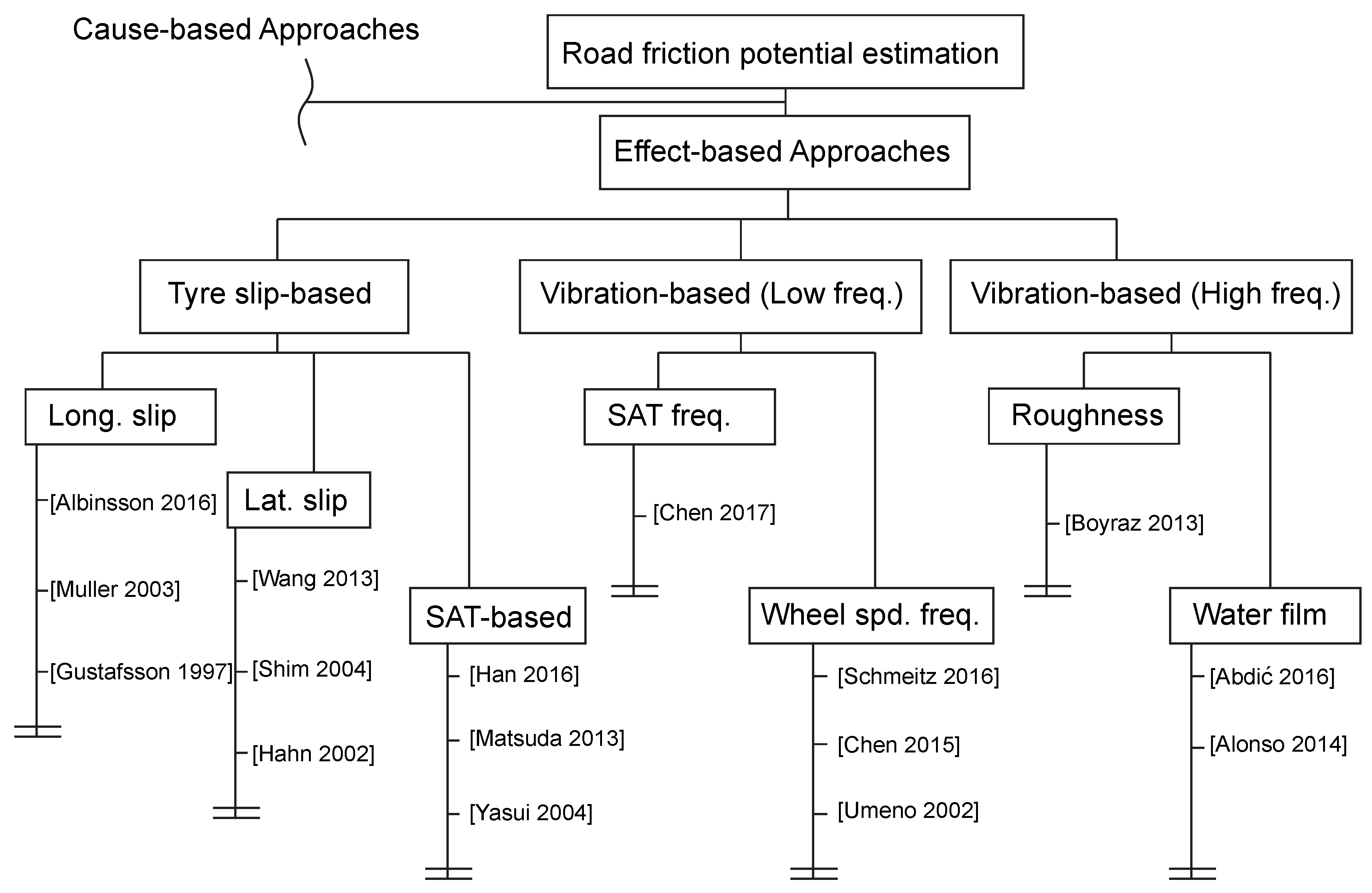
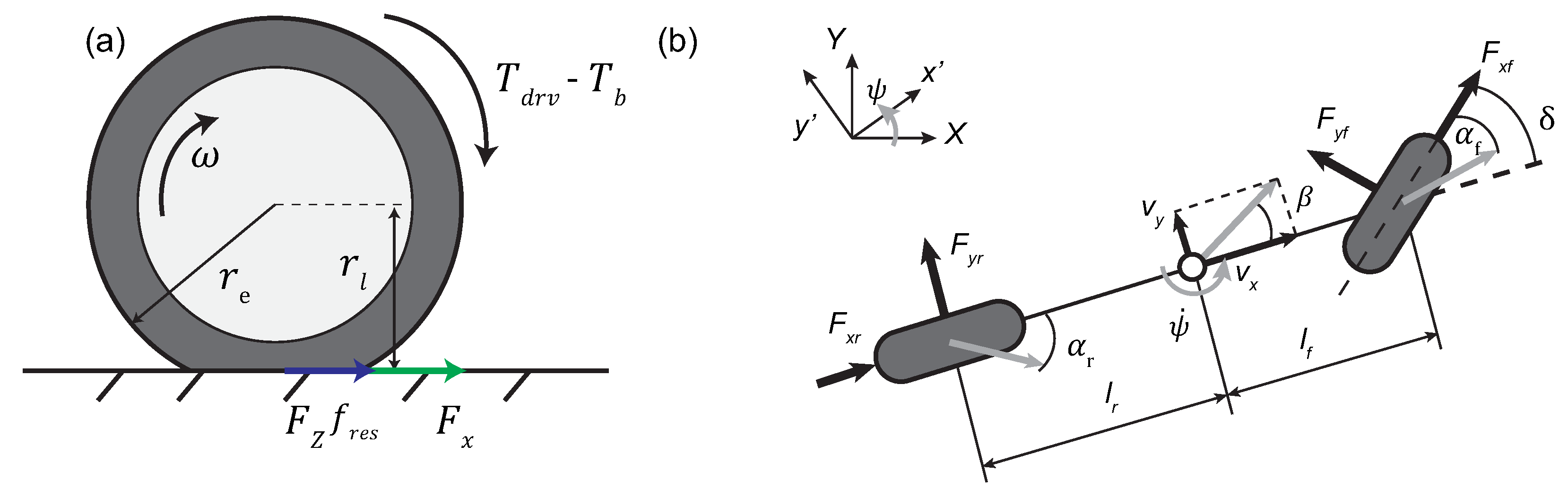
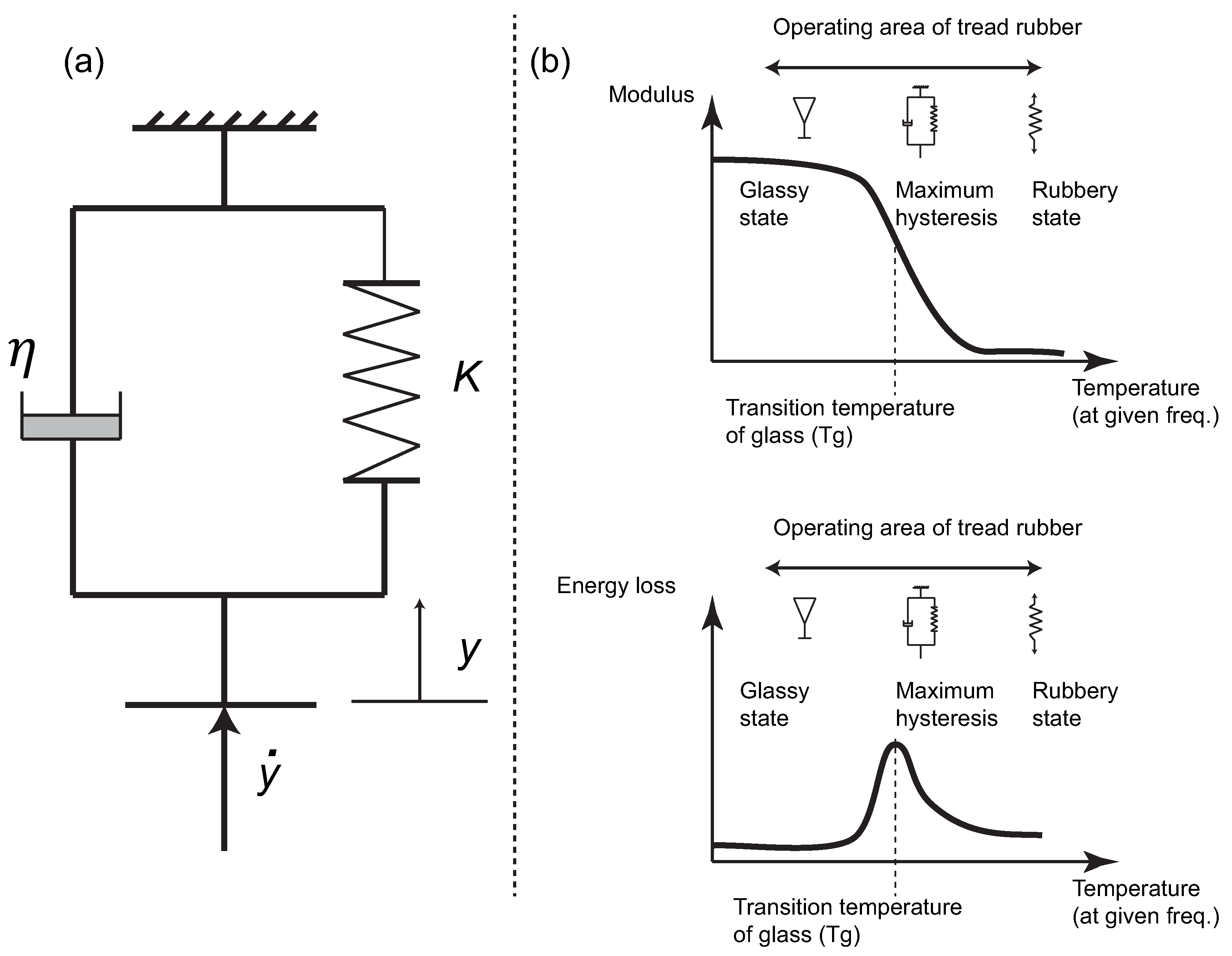
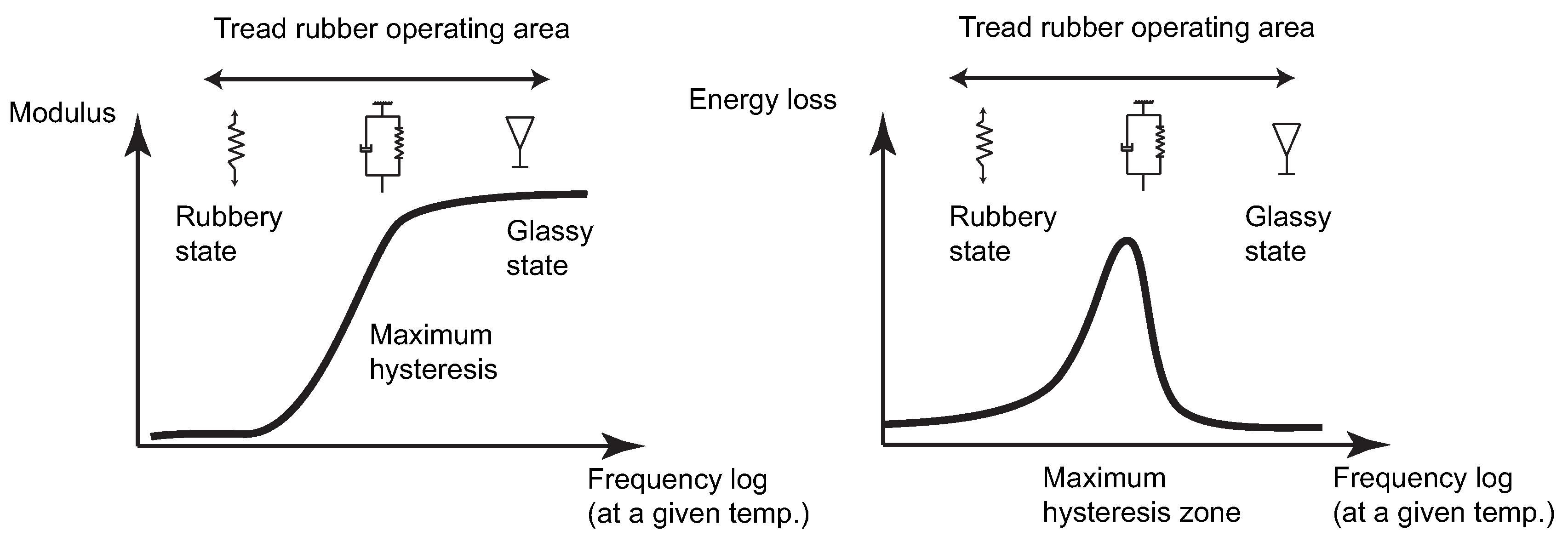
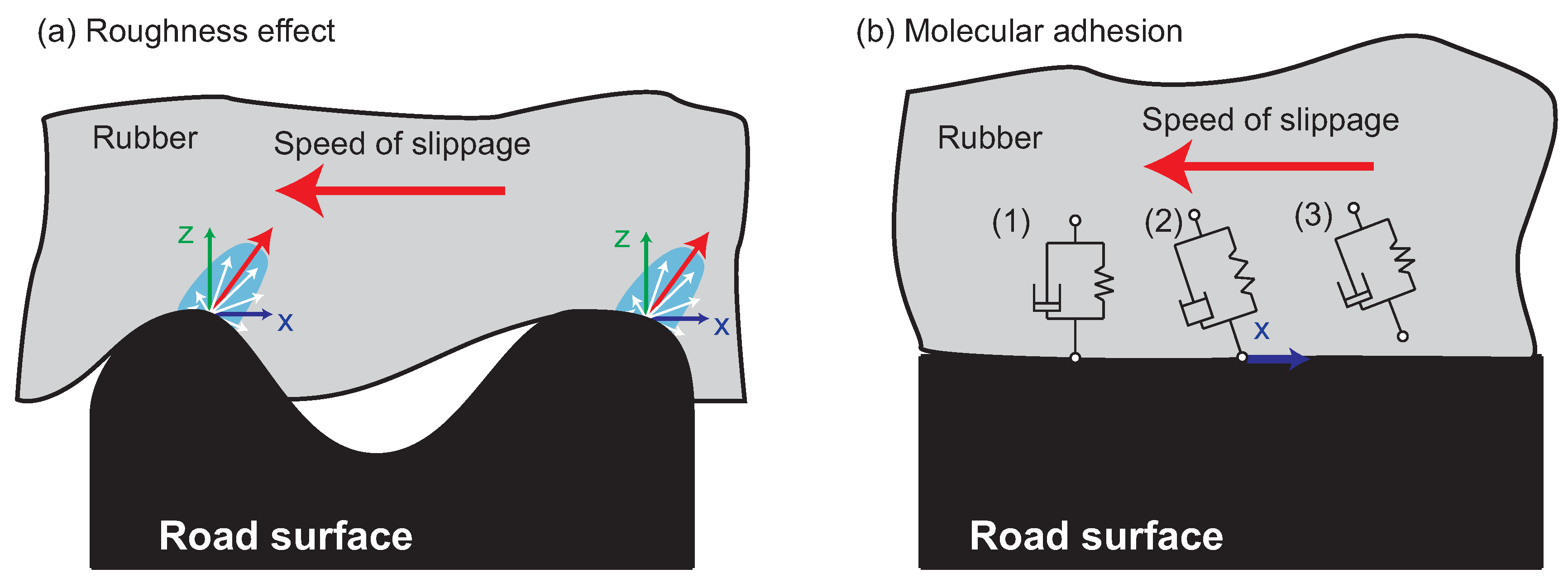
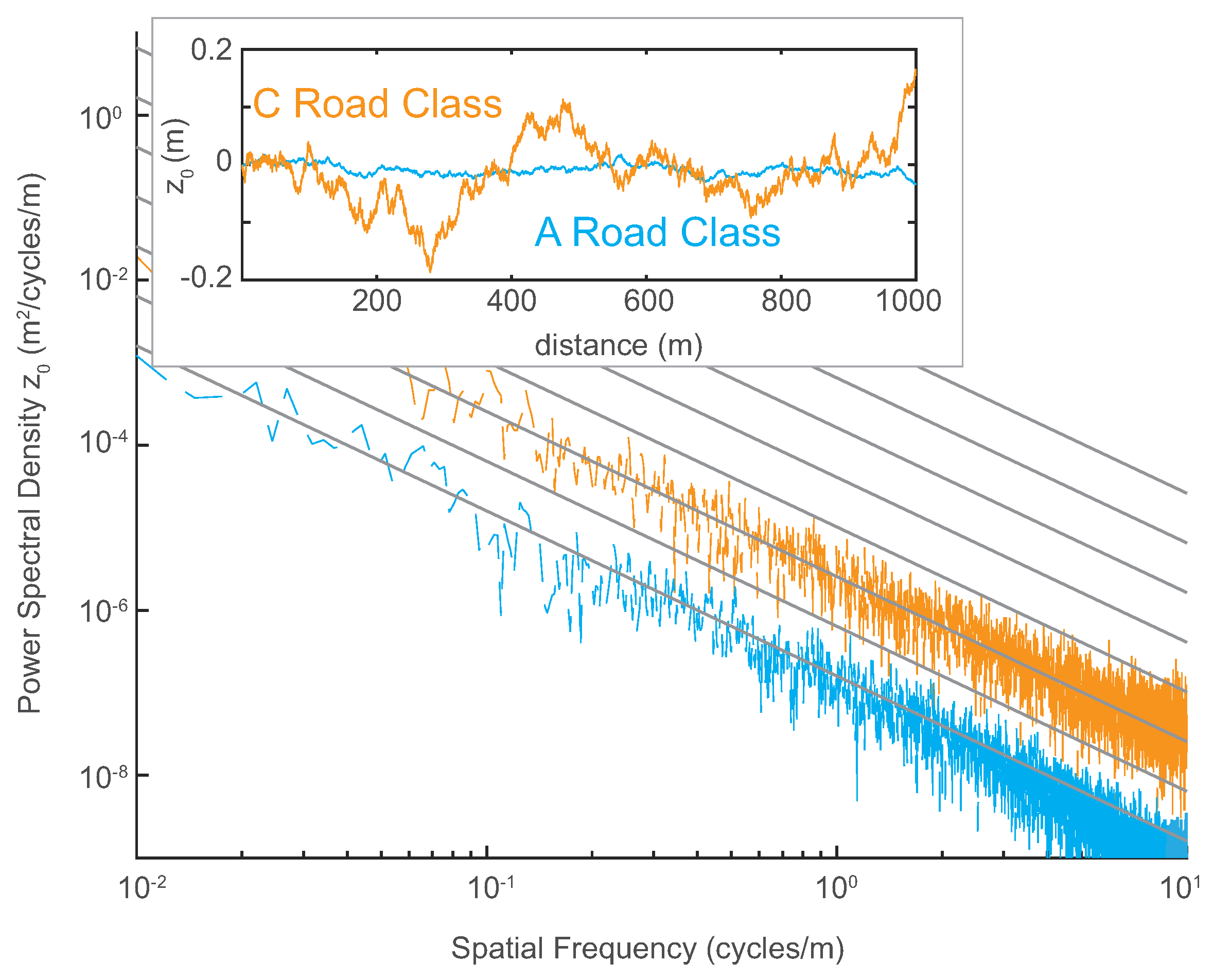
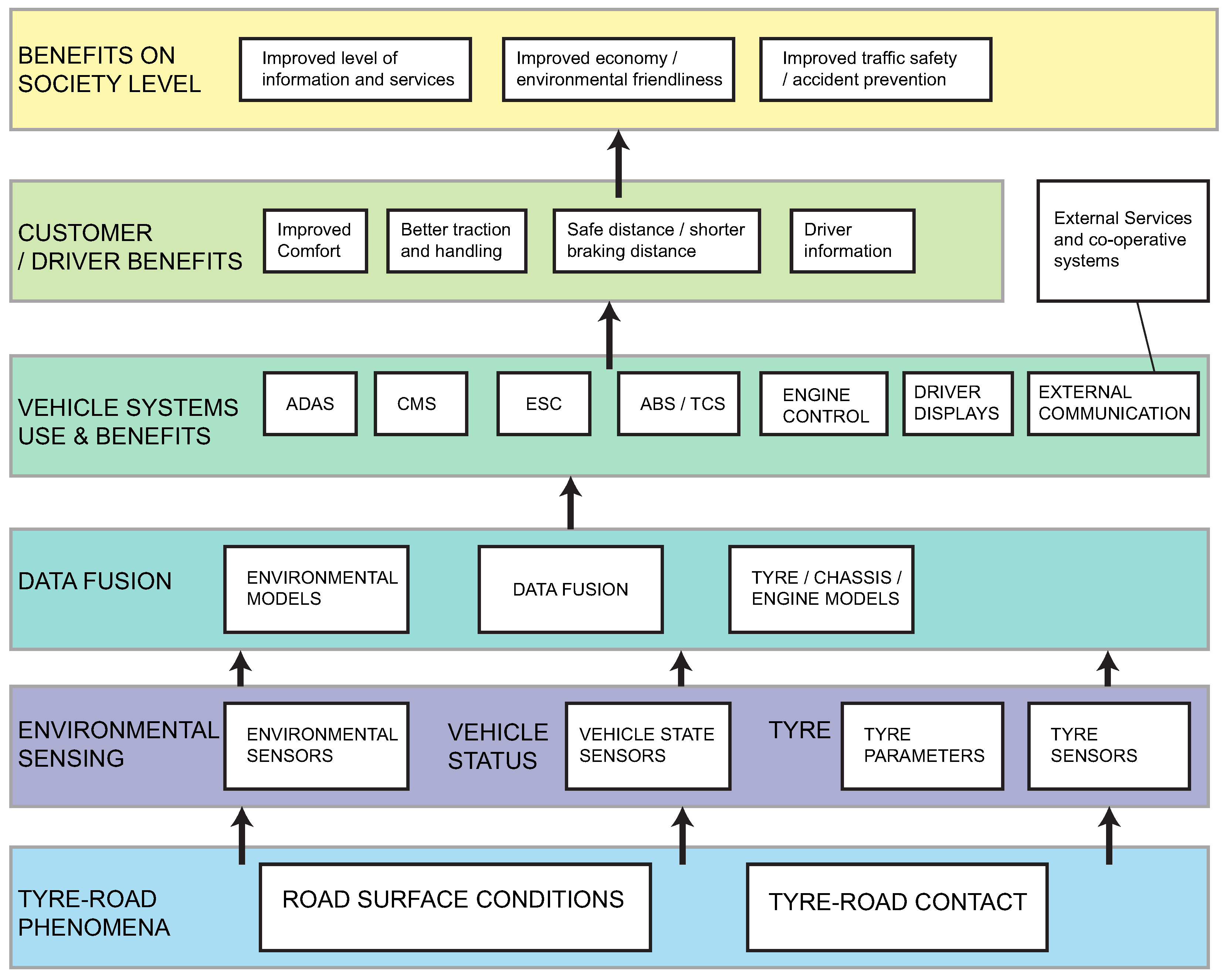
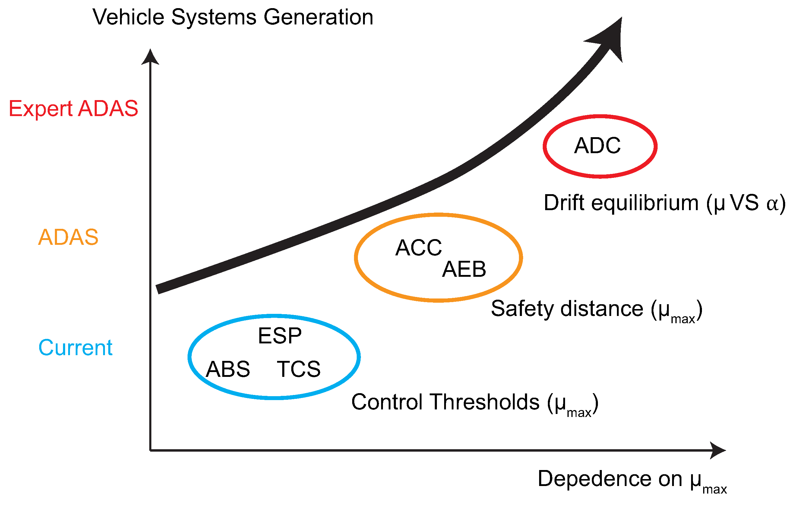
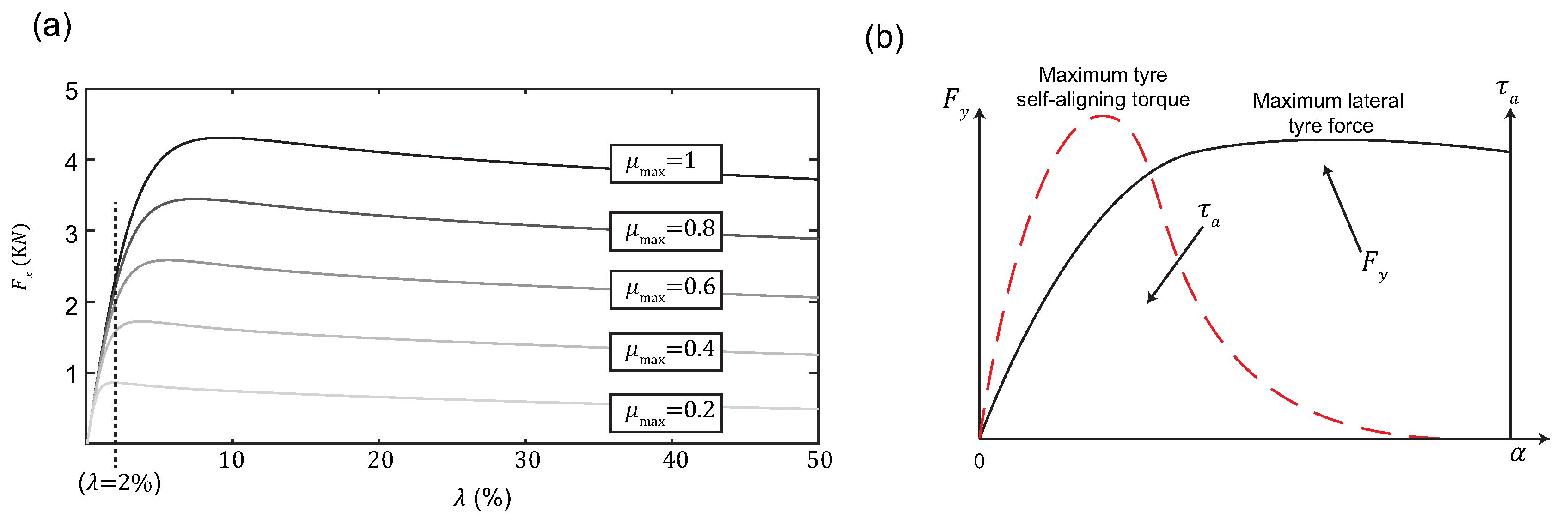
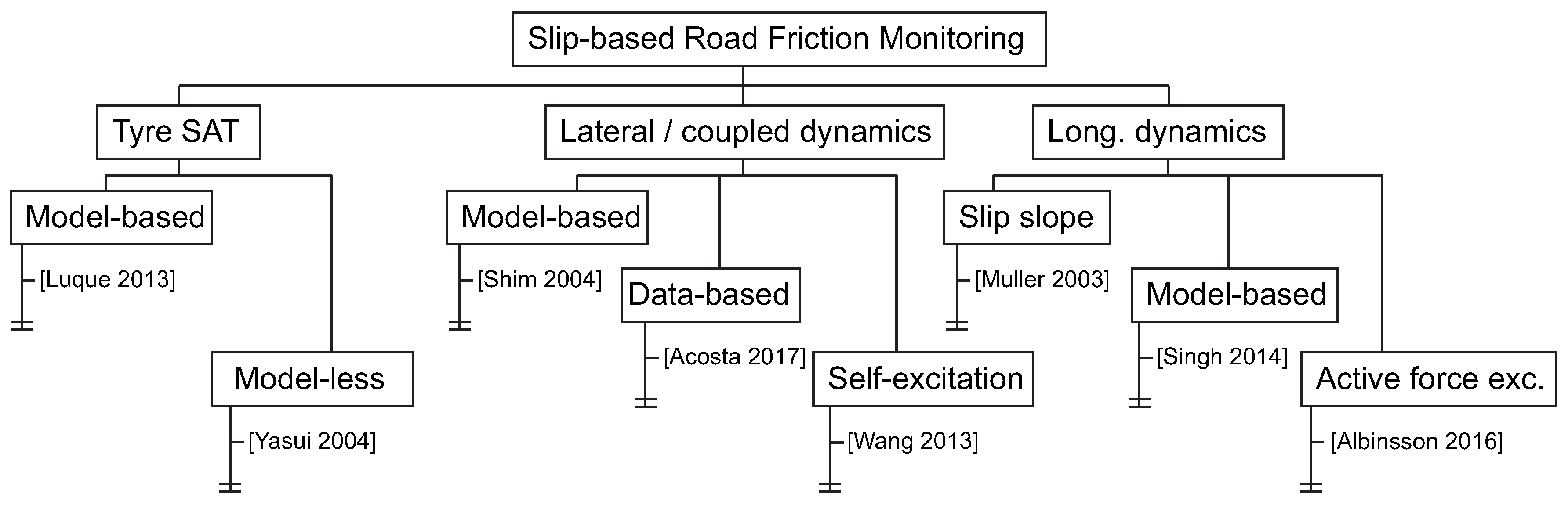
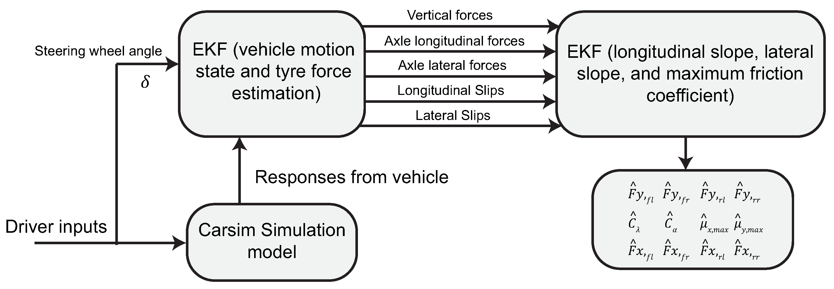
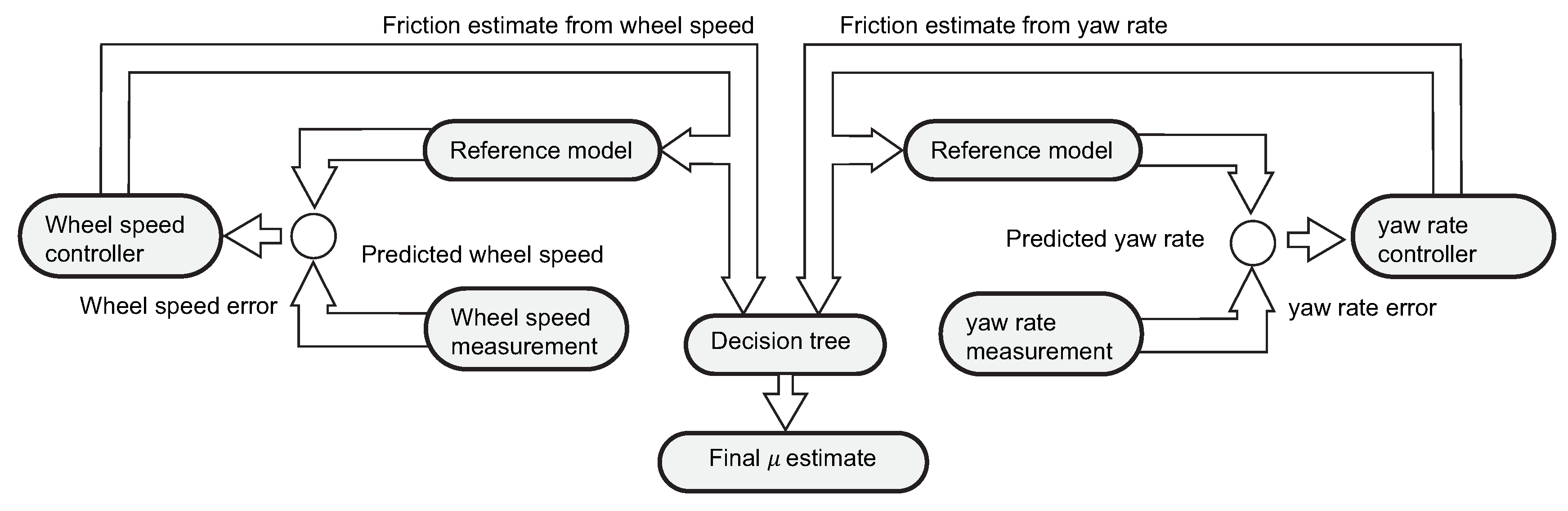
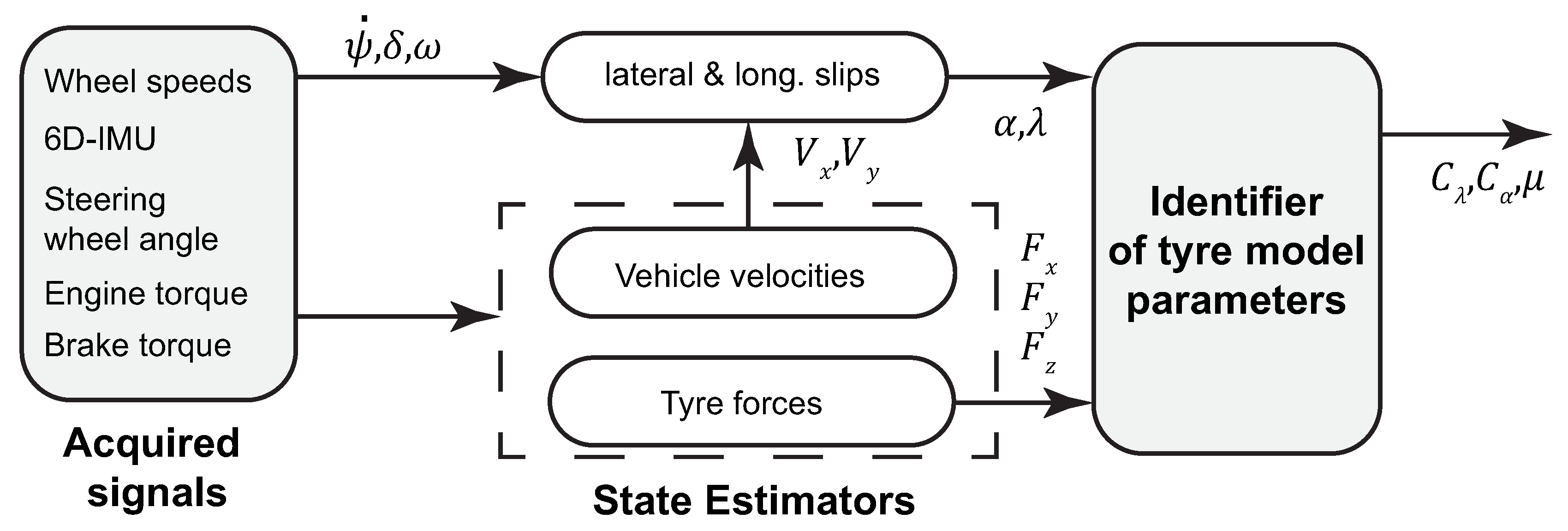
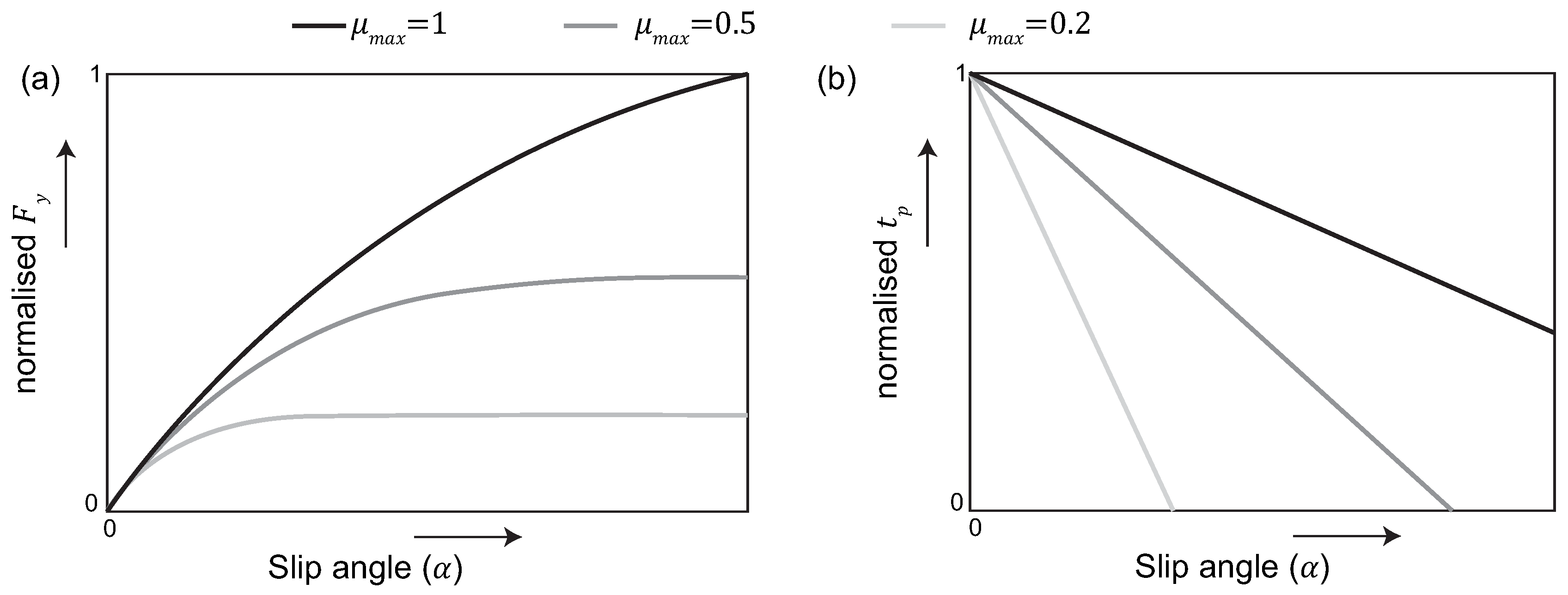
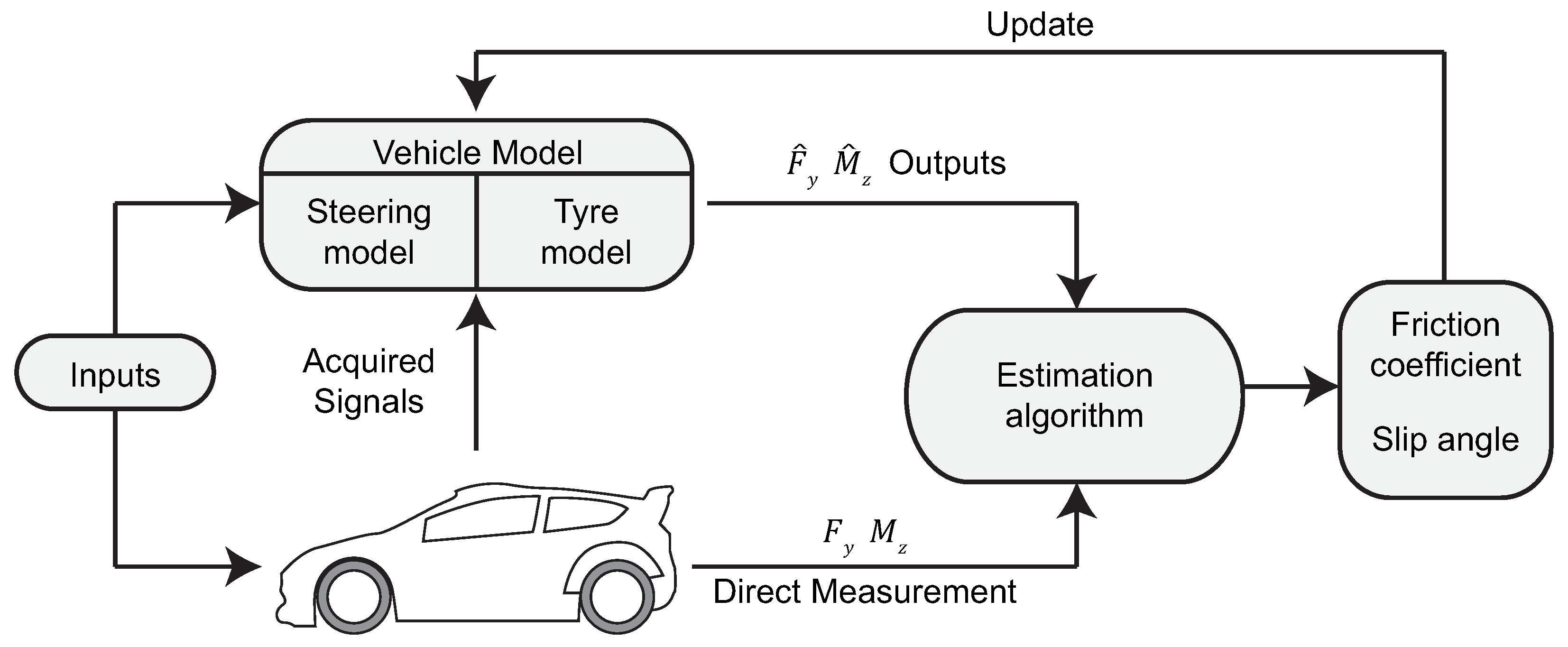
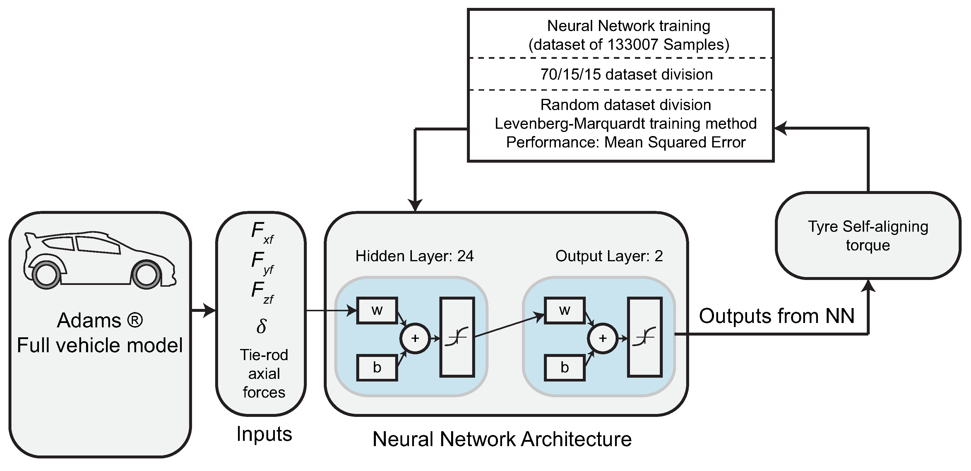
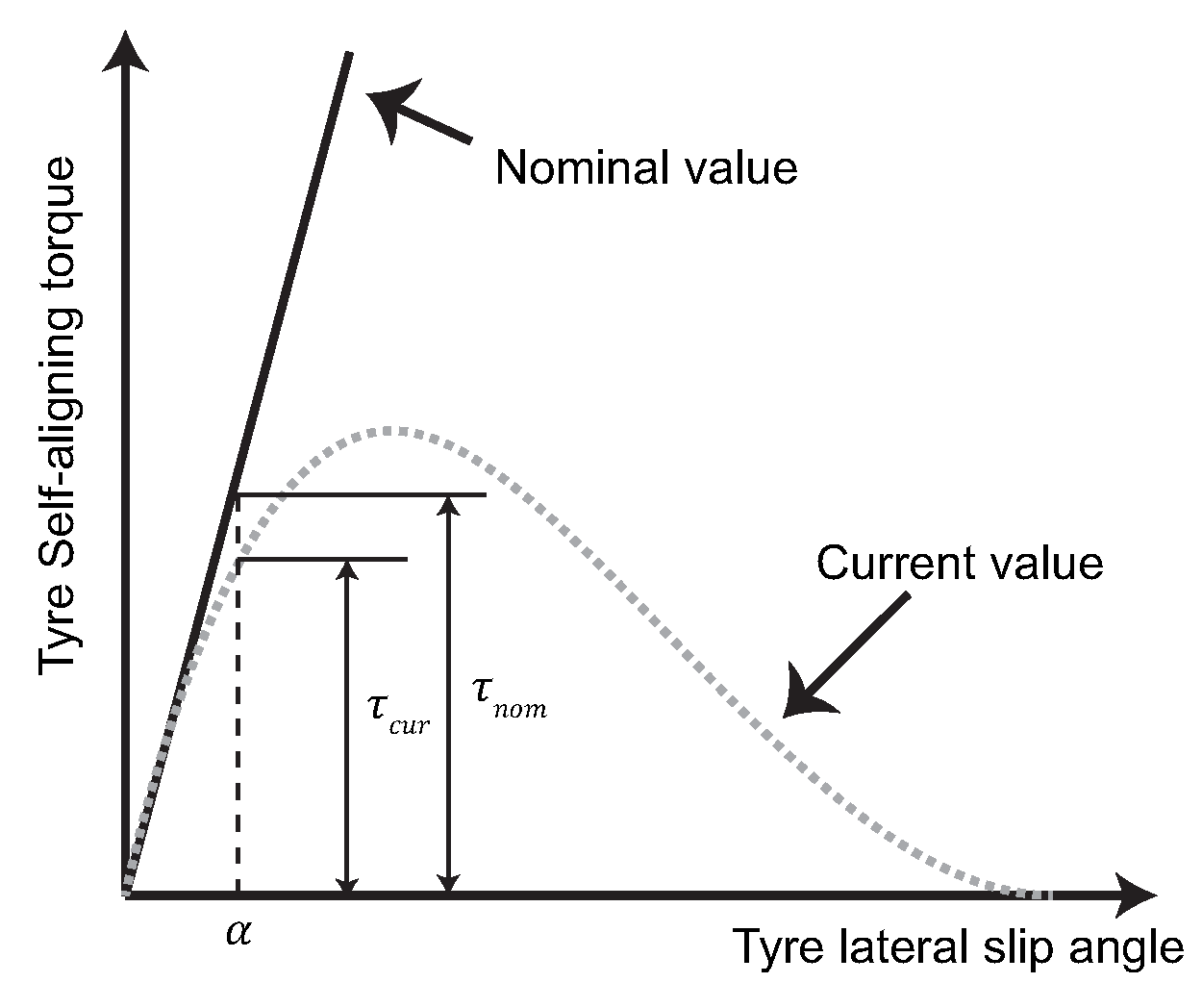
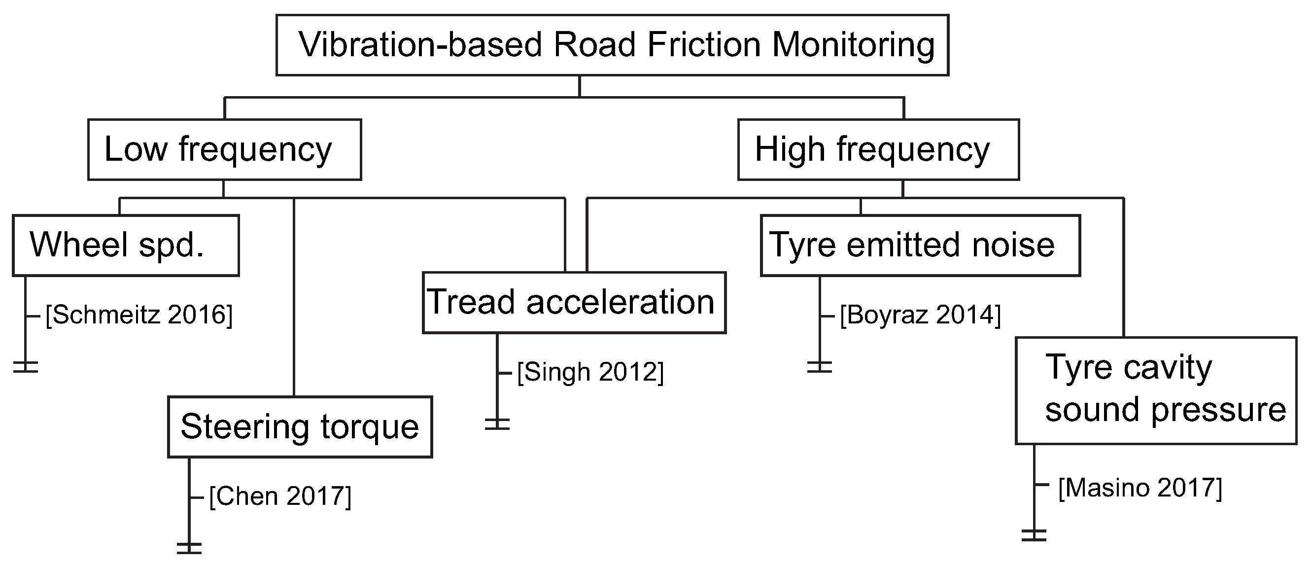
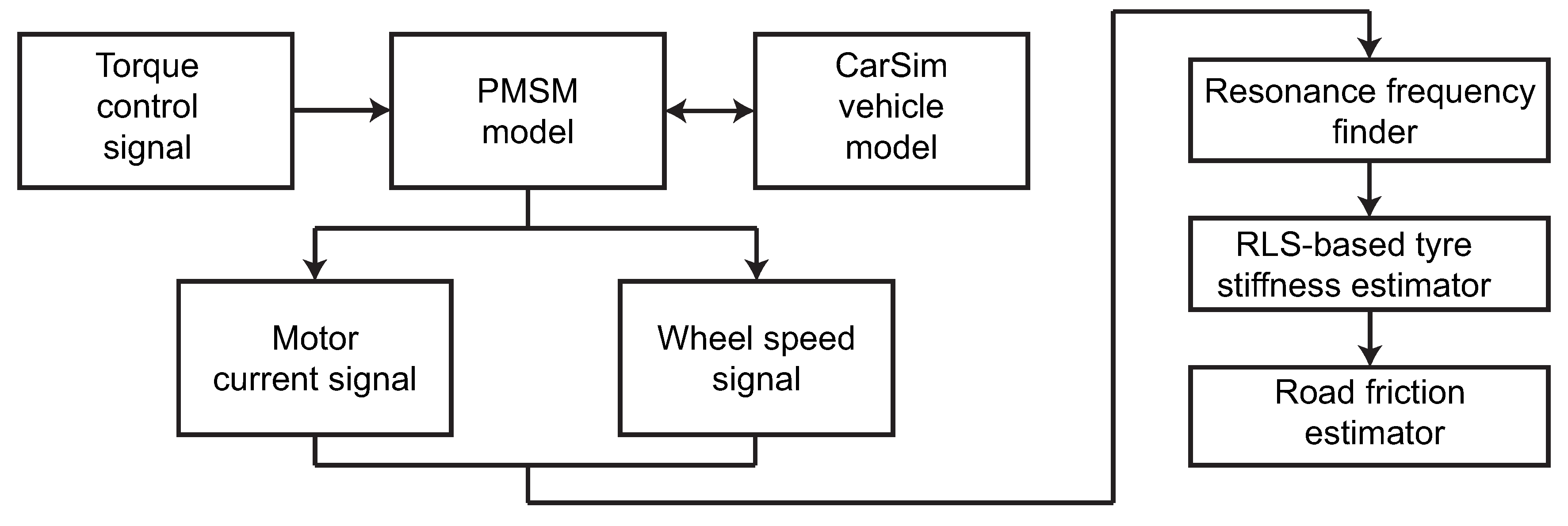
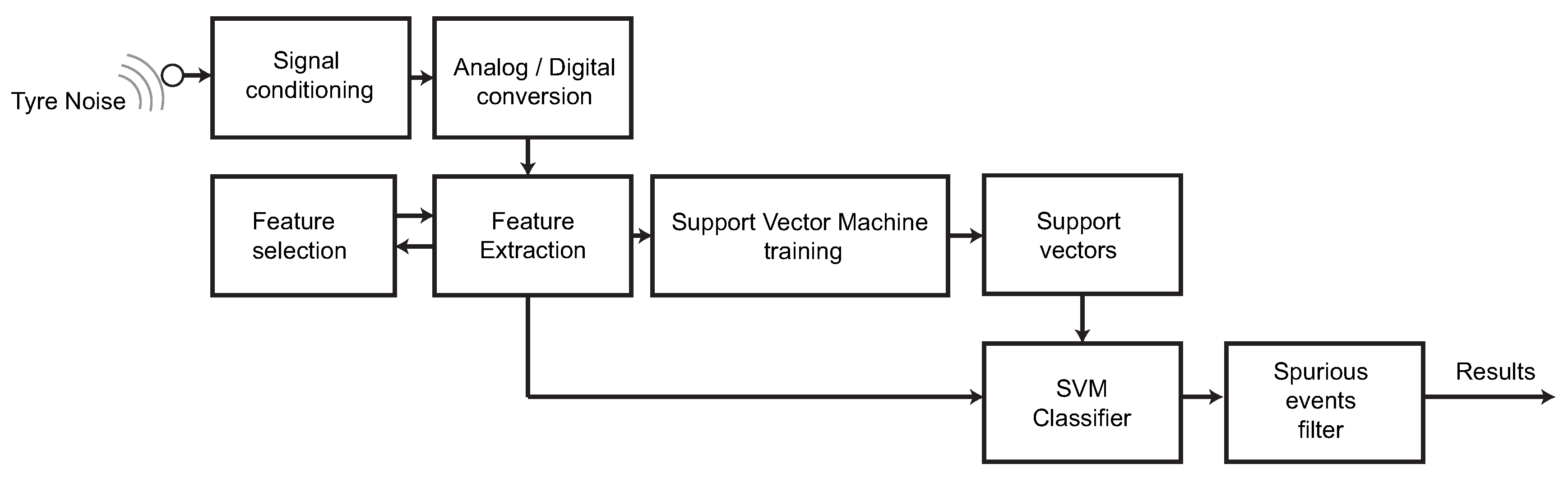
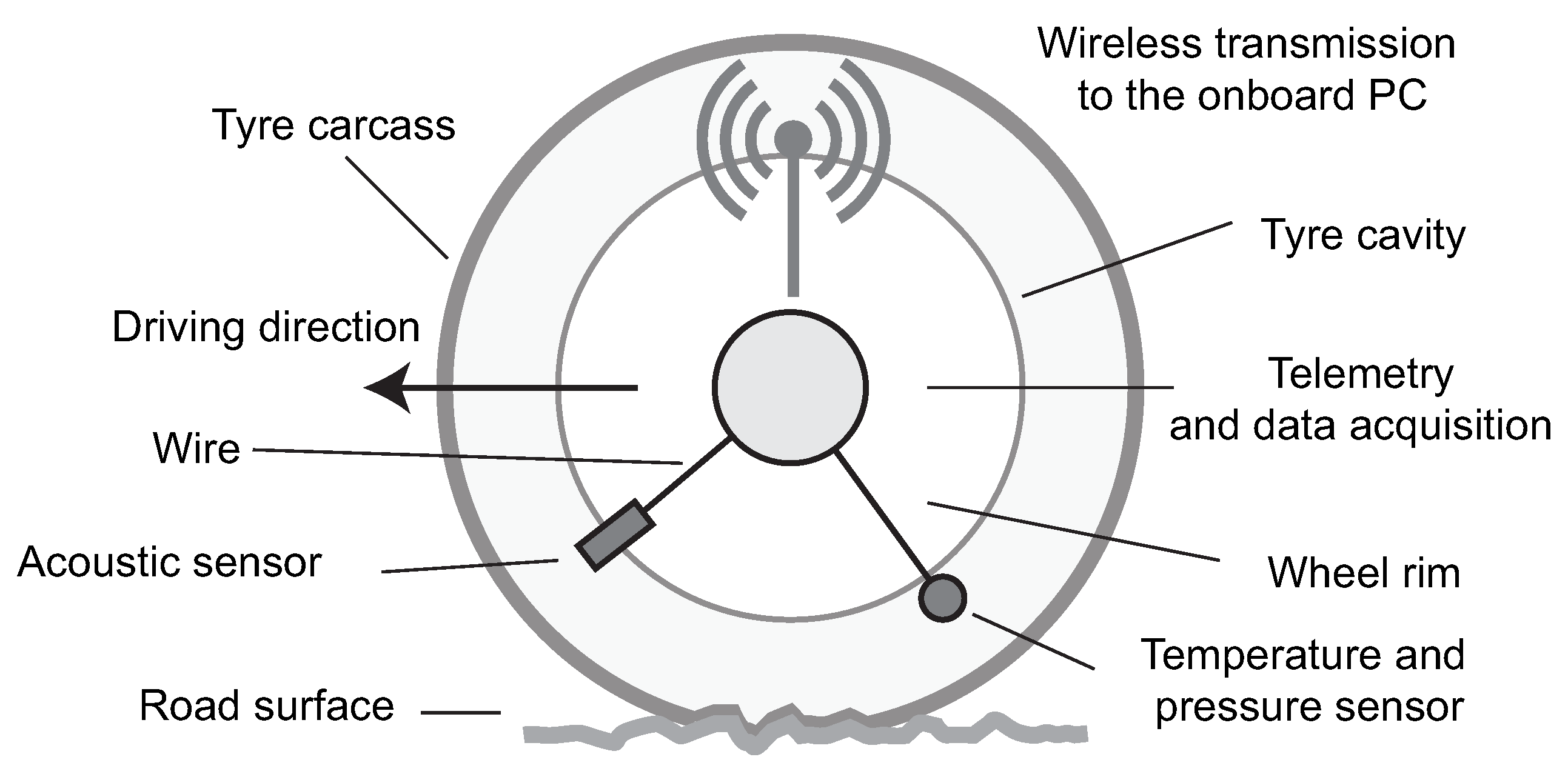
Table 1.
Friction coefficient for four different broad categories of wet road surfaces [2].
Table 1.
Friction coefficient for four different broad categories of wet road surfaces [2].
| Road Category | Friction Coefficient Range |
|---|---|
| Macro rough/micro rough surface (draining mixes, bituminous concretes) | 0.5–0.9 |
| Macro smooth/micro rough surface (fine mixes) | 0.4–0.8 |
| Macro rough/micro smooth surface (rolled aggregates) | 0.2–0.3 |
| Macro smooth/micro smooth surface (flushing asphalt) | 0.1–0.2 |
Table 2.
Slip slope and ranges obtained in [7].
Table 2.
Slip slope and ranges obtained in [7].
| Road | |||
|---|---|---|---|
| Dry asphalt | 23 | 40 | [0.85,1.15] |
| Soapy asphalt | 17 | 28.2 | [0.45,0.75] |
Table 3.
Longitudinal stiffness values obtained in [17].
Table 3.
Longitudinal stiffness values obtained in [17].
| Tyre Parameter | Concrete | Snow | Ice |
|---|---|---|---|
| [0.85–1] | [0.35–0.4] | [0.15–0.2] | |
Table 4.
Longitudinal stiffness changes for different tyre temperature, inflation pressure, tread depth, normal load, and road surface wetness [129].
Table 4.
Longitudinal stiffness changes for different tyre temperature, inflation pressure, tread depth, normal load, and road surface wetness [129].
| Longitudinal Stiffness Variation (%) | ||
|---|---|---|
| Test | Tyre 1 | Tyre 2 |
| Cold to steady-state temperature | −17% | −21% |
| −10% pressure | 17% | 15% |
| −20% pressure | 29% | 28% |
| Reduced tread (2.5 mm) | 34% | 91% |
| +200 kg (normal load ) | 13% | 7% |
| +400 kg (normal load ) | 60% | 42% |
| Wet road | 4% | −2% |
Table 5.
Values of the peak frequency , undamped natural frequency , and damping ratio of the first mode of the tyre for different longitudinal slip stiffness scaling factors LKX, [50].
Table 5.
Values of the peak frequency , undamped natural frequency , and damping ratio of the first mode of the tyre for different longitudinal slip stiffness scaling factors LKX, [50].
| LKX | |||
|---|---|---|---|
| 1 | 35.9 Hz | 34.8 Hz | 0.17 |
| 0.5 | 34.1 Hz | 32.0 Hz | 0.24 |
| 0.2 | 29.9 Hz | 23.2 Hz | 0.44 |
Table 6.
Summary of low frequency vibration contributions on friction estimation.
| Reference | Hypothesis | Method | Frequency Range |
|---|---|---|---|
| Umeno et al. [51] | Friction influences damping of tyre vibrations | Transfer function—Tyre rotational vibrations | 20–60 Hz |
| Chen et al. [4] | Longitudinal slip stiffness is linearly dependent on friction | Resonance frequency of the driveline of an in-wheel motor drive system | 15–22 Hz |
| Schmeitz and Alirezaei [50] | normalised slip slope factor LKX is dependent on friction coefficient | Simulations using MF-Swift tyre model | 23–36 Hz |
| Chen et al. [130] | tyre self-aligning torque (SAT) stiffness varies linearly with the road friction potential | Resonance frequency of the electric power steering system | 0.5–1.6 Hz |
Table 7.
Summary of high frequency vibration contributions on friction estimation.
| Reference | Hypothesis | Method | Frequency Range |
|---|---|---|---|
| Boyraz [46,131] | Features of the acoustic signal depend on the friction coefficient | Linear predictive coefficients, mel-frequency cepstrum coefficients and power spectrum coefficients, Artificial Neural Networks | Not specified |
| Alonso et al. [49] | Features of the acoustic signal depend on the friction coefficient | Audio samples 20 Hz-20 kHz, Support Vector Machines | 500 Hz to 8 kHz |
| Masino et al. [47,132] | acoustic signal in the tyre cavity | Power Spectral Density | >5000 Hz |
| Singh et al. [77] | tyre circumferential acceleration and the road friction potential | In-tyre accelerometer measures vibrations, ratio of vibrations at low and high frequency range | 10–500 Hz and 600–2500 Hz |
Table 8.
Major advantages and disadvantages of the approaches presented in this review.
| Method | Excitation Direction | Description | Advantages | Disadvantages |
|---|---|---|---|---|
| Slip-based | Longitudinal | Slip slope | Approach easiness | Contradictory results High variability |
| Slip-based | Longitudinal | Friction Model-based | Accuracy | High excitation required e.g., ABS braking |
| Slip-based | Longitudinal | Active force excitation | Cons. speed conditions | “when”? Blind to mu transitions |
| Slip-based | Lateral | Friction Model-based | Accuracy | High excitation required Nonlinear cornering region |
| Slip-based | Lateral | Data-based | No model required | Experimental data needed Extrapolation issues |
| Slip-based | Tyre SAT | Friction Model-based | Accuracy Lowest excitation among slip-based | Pneumatic trail estimation EPS requirement Mech. trail compensation |
| Slip-based | Tyre SAT | Data-based | No model required | Experimental data needed Extrapolation issues |
| Slip-based | Tyre SAT | LGM | Easiness Low excitation | Lack of detailed analysis Existing studies focused on stability controller validation |
| Method | Frequency band | Description | Advantages | Disadvantages |
| Vibration-based | Low | Resonance frequency | Reduced excitation required | Contradictory results High variability |
| Vibration-based | High | Noise | Reduced excitation required | Based on empirical results Selection of feature vector |
© 2017 by the authors. Licensee MDPI, Basel, Switzerland. This article is an open access article distributed under the terms and conditions of the Creative Commons Attribution (CC BY) license (http://creativecommons.org/licenses/by/4.0/).
Share and Cite
MDPI and ACS Style
Acosta, M.; Kanarachos, S.; Blundell, M. Road Friction Virtual Sensing: A Review of Estimation Techniques with Emphasis on Low Excitation Approaches. Appl. Sci. 2017, 7, 1230. https://doi.org/10.3390/app7121230
AMA Style
Acosta M, Kanarachos S, Blundell M. Road Friction Virtual Sensing: A Review of Estimation Techniques with Emphasis on Low Excitation Approaches. Applied Sciences. 2017; 7(12):1230. https://doi.org/10.3390/app7121230
Chicago/Turabian StyleAcosta, Manuel, Stratis Kanarachos, and Mike Blundell. 2017. "Road Friction Virtual Sensing: A Review of Estimation Techniques with Emphasis on Low Excitation Approaches" Applied Sciences 7, no. 12: 1230. https://doi.org/10.3390/app7121230
Note that from the first issue of 2016, this journal uses article numbers instead of page numbers. See further details here.