Bi-Level Programming Approach for the Optimal Allocation of Energy Storage Systems in Distribution Networks

State Key Laboratory of Advanced Electromagnetic Engineering and Technology, Huazhong University of Science and Technology, Wuhan 430074, Hubei, China
*
Author to whom correspondence should be addressed.
Appl. Sci. 2017, 7(4), 398; https://doi.org/10.3390/app7040398
Submission received: 12 March 2017
/
Revised: 5 April 2017
/
Accepted: 12 April 2017
/
Published: 14 April 2017
(This article belongs to the Special Issue Distribution Power Systems)
Abstract
:Low-CO2-emission wind generation can alleviate the world energy crisis, but intermittent wind generation influences the reliability of power systems. Energy storage might smooth the wind power fluctuations and effectively improve system reliability. The contribution of energy storage to system reliability cannot be comprehensively assessed by the installed capacity of energy storage. The primary goal of this paper is to investigate the impact of the installed location and capacity of energy storage on power system reliability. Based on a bi-level programming approach, this paper presents a bi-level energy storage programming configuration model for energy storage capacity and location configuration. For upper-level optimization, a depth search method is utilized to obtain the optimal installed location of energy storage. For the lower-level optimization, the optimal capacity of energy storage is solved to meet the system reliability requirements. The influence of the contribution of energy storage location to system reliability is analyzed. The proposed model and method are demonstrated using the RBTS-Bus6 System and Nanao (NA) island distribution system in China. The results show the effectiveness and practicability of the proposed model and method.
1. Introduction
In recent years, the installed capacity of wind generation has significantly increased across the world. Wind power generation can effectively ease the reliance on fossil fuels, and reduce carbon dioxide emissions from fossil fuels.
However, with the rapid growth of wind power penetration, wind power still faces significant challenges in power generation reliability because of its intermittence and randomness. The application of energy storage in distribution systems may provide contingency services and enhance system reliability [1,2]. In a distribution system integrated with wind power and energy storage, the energy storage system also plays an important role in peak load shifting. Therefore, the optimal siting and sizing of an energy storage system can help to effectively improve system reliability and the ability of a grid to incorporate wind power.
The installation of energy storage can benefit distribution system operator (DSO), the transmission system operator (TSO), the independent system operator (ISO) and customers. Therefore, the influence of different configurations of the installed size and sites on system reliability must be analyzed. Most studies on the allocation of energy storage are mainly focused on two aspects: (1) the sizing configuration of energy storage [2,3,4,5,6,7] and (2) the siting allocation of the energy storage [8,9,10,11,12,13]. For the studies on the capacity configuration of energy storage, the optimization configuration of the installed capacity of energy storage is considered based on certain related factors in the power system, including the changes in wind power [3,14], the cost fluctuation of renewable energy [4], the spatial-temporal model of wind power [5] and other renewable energy networks [2,7]. The optimization objective of the existing studies can be classified as follows: avoid wind curtailment [15], minimize operational cost and investment [16,17,18,19], minimize power rating [20], minimize the overall system cost [21], minimize electricity cost [22], avoid voltage violation [23] and improve reliability [24,25,26,27]. The optimization allocation size and location of energy storage is used to prevent load curtailment and minimize operational cost [11,12]. The optimal size and location of energy storage can also maximize wind power utilization [9]. The methods for solving these optimization problems include linear programing [21,23], second-order cone programming [19], exhaustive searches [13,20], genetic algorithms [9], particle swarm optimization [10,11], artificial bee colonies [17] and bat algorithms [18]. Relatively few studies have been conducted on the optimal configuration of the siting and size of energy storage or on which optimization objective regarding the installed location of energy storage is the most considered investment: operational costs or losses [8]. Moreover, in the existing studies, the energy storage location is always considered the constraint on the power system operation cost in the optimization [10,11,12]. The existing studies do not consider the energy storage system as an independent influencing factor for the system reliability, and they have failed to properly consider the effects of the energy storage location on power system reliability. A reasonable allocation scheme is established for the energy storage in a distribution network based on the required system reliability. It is necessary to separately evaluate the influence of energy storage system on reliability in power system planning. Different installation locations should yield different contributions of an energy storage system to the power system benefits [13]. An energy storage system will not be fully able to improve reliability at an improper installation point. Moreover, the positive influence of the energy storage system would be magnified with increasing wind power penetration. For power system planners, the installed capacity and location of energy storage are not easy to change once determined. In this context, this paper focuses on the allocation of energy storage devices in the distribution system and attempts to contribute to the size and site planning of energy storage systems. A bi-level programming approach is applied to evaluate the influence of location and installed capacity of energy storage on the reliability of power system. The bi-level programming approach provides a theoretical method for the rational allocation of energy storage capacity and position.
Specifically, the key contributions of this work can be summarized as follows:
- Presenting an optimization problem that represents the sizing and siting of an energy storage system allocation in distribution systems. The novel optimal method to allocate the energy storage system determines the capacity and location of the energy storage system, which maximizes the system reliability improvement and minimizes the energy storage installation capacity. The sizing and siting of an energy storage system cannot be considered separately from the energy storage system planner; thus, the bi-level programming model takes into account both energy storage system size and site allocation, and this approach provides a consistent method to calculate the available capacity of an energy storage system;
- Developing an efficient algorithm to solve the bilevel optimization problem. The impact of minimizing the installation capacity of an energy storage system on distribution system reliability improvement is analyzed. As a result, the original linear bilevel program with bilinear terms is transformed as a single-level linear equivalent that overcomes the shortcomings of the available solutions in industry practice and in the technical literature. This paper also introduces a search tree algorithm for solving the siting selection optimal problem in energy storage system planning and for identifying the optimal installation position of an energy storage system. The algorithm effectively reduces the calculations.
- Illustrating the impacts of the influencing factors of distribution networks integrating wind power and energy storage systems and providing a reasonable and effective basis and a practical way to improve the system reliability, aiming at the role of key influences for the energy storage system allocation. The key installation points are analyzed, and the available solutions can be used in industry practice.
2. Problem Formulation
The distribution network includes wind generators, an energy storage system, conventional generators, and a load demand. The energy storage system is utilized to satisfy the load demands that exceed the available capacity of distributed generations (DGs). The configuration of the energy storage system is an optimization problem to identify its optimal installation capacity and location. The objective of this paper is to provide an optimization allocation scheme of battery energy storage systems for distribution networks integrated with renewable energy. The objective problem includes two items, the capacity configuration and the location configuration of energy storage. The capacity configuration model identifies the installed capacity of energy storage to maintain a certain system reliability. On this basis, the location configuration model improves the contribution of energy storage by optimizing the energy storage installation location.
The optimization problem has the following two characteristics: (1) the two optimization objectives, the installation capacity and location of the energy storage system, have their own control variables, and the control variables may vary to achieve the optimization objective; (2) the optimization objective of the installation capacity of the energy storage system has a higher priority, and the optimization of the installation position of the energy storage system can be adjusted for the optimization. Moreover, the installation position of the energy storage system will influence the results of the capacity optimization. In this paper, bi-level programming is applied to the optimization problem of the installation position and capacity allocation of energy storage in distribution networks.
Bi-level programming was first proposed by McGill and Bracken in 1973 [28]. Bi-level programming has been widely applied in the field of economic management [29,30,31] and engineering technology [28]. In power system research, bi-level optimization has also been widely applied in research on the pricing and profit problem of power systems [32,33,34,35,36], reactive power optimization [28,37] and transmission capability evaluation.
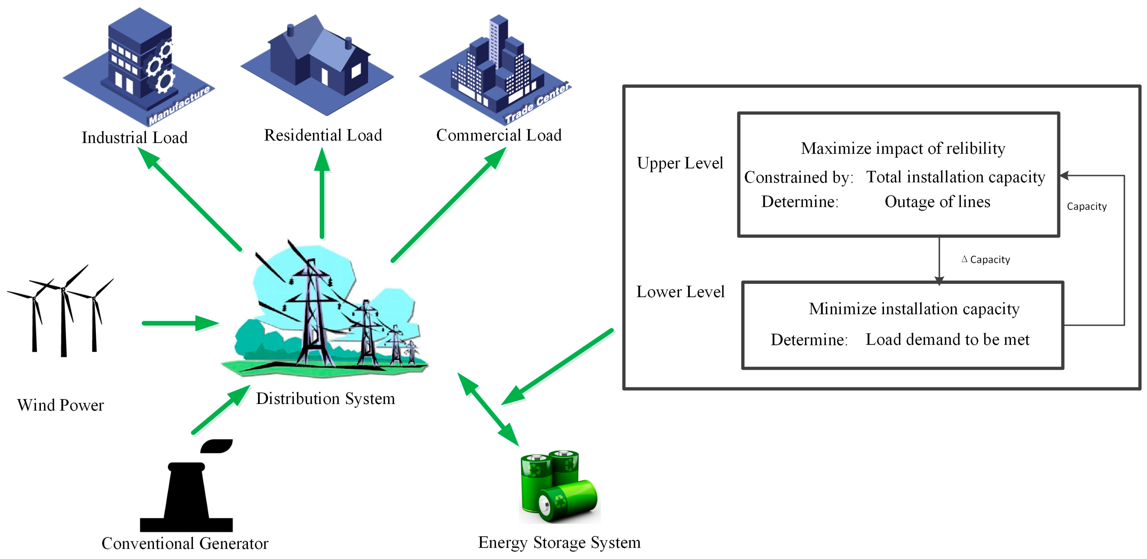
Figure 1 shows the structure of the distribution network studied in this paper. There are wind generators, energy storage devices and loads in the distribution networks. The load demand includes residential, commercial and industrial loads.
The allocation of an energy storage system is characterized in terms of the dual variables of the installation location and installation capacity of an energy storage system. In other words, the installation capacity of an energy storage system considering the distribution reliability requirement is an optimization problem in itself. This optimization includes linear constraints terms and provides the optimal installation capacity associated with the reliability level. Therefore, since the allocation of an energy storage system is dependent on both the installation capacity and location variables, the above-described practical procedure to obtain the pricing and profit optimization is also suitable for the energy storage system allocation considering sizing and siting. Hence, based on the above analysis, the proposed reliability constrained energy storage system allocation planning can be formulated as the following linear bilevel programming problem:
subject to
where resolves
subject to
The above bilevel problem consists of an upper-level optimization Equations (1)–(3) and a lower-level optimization Equations (4)–(6). In the bi-level programming model of energy storage allocation, the objective function of the upper-level optimization is to identify the optimal installation site of the energy storage to obtain the optimized system reliability. Meanwhile, the lower-level problem is to identify the optimal installation capacity of an energy storage system to satisfy the reliability requirements. is the energy storage installation capacity and the solution of is resolved from the lower-level optimization. represents the location of the energy storage system. The variables of problem are divided into two classes, namely the upper-level variables and the lower-level variables . Similarly, the Equations (1), (2), (4) and (5) are the upper-level and lower-level objective functions respectively, while the vector value Equations (3) and (6) are called the upper-level and lower-level constraints, respectively. Upper-level constraints involve variables from both levels.
2.1. Capacity Configuration Model of Energy Storage
The capacity evaluation model is established in this section to identify the installation capacity of an energy storage system as maintaining a certain reliability level. The lower-level objective function is given as
where is a certain reliability of the distribution network and can be determined by the operators and is the installation capacity of energy storage. The lower-level optimization is identical to the energy storage capacity allocation problem associated with the optimal values of the upper-level decision variable , the location of energy storage. Equation (7) aims to obtain the minimum installation capacity of energy storage that satisfies the required system reliability.
In addition to the failure rate of wind turbines, the intermittent characteristic also causes the fluctuation of the output power of wind turbines; therefore, it should be considered in the evaluation of the contribution of renewable energy to generator adequacy. Hence, the system average interruption duration index (SAIDI) during period T is utilized to represent the reliability of the distribution network. Therefore, SAIDI in period T before energy storage system installation is shown below
where is the total number of the customers in the distribution network and is the period of user outage at time t. In addition, is described as
At time , the total available capacity of conventional generator is , the total available capacity of the wind power generator is , and the load demand is .
After the energy storage system is installed, is calculated as
where is the added load demand to offset the influence of the added energy storage on the system reliability.
In Equation (10), the added load is used to balance the effects of the energy storage system on power system reliability. The power system with the added load and energy storage system should reach the reliability of the original system.
Therefore, the relationship between system reliability and available generator capacity is
The objective function is subjected to constraints Equations (13)–(26). The constraints of the optimization problem include power flow, stability and security constraints. The optimization results of Equation (7) are influenced by two types of factors: the power system status factor and the power system operation status.
The constraints of the energy storage installation capacity model include the constraints of system balance, conventional generators, wind power generation and energy storage.
2.1.1. System Power Balance Constraints
The system power should maintain balance at any moment. The total available generator capacity is equal to the load demand in distribution networks, and the function is represented by Equation (13) [32].
where , and are the output power of the conventional generator, wind turbine and energy storage, respectively. is the load demand.
2.1.2. Conventional Generator Constraints
The conventional generator constraint includes the active power constraint and the reactive power constraint.
where is the working condition of the conventional generator at time t. When the generator is out of work, the value of is 0. Otherwise, it is 1.
2.1.3. Wind Power Generator Constraints
Wind Power Output Power Constraint
The historical wind speed data of Prince Albert in Canada, from year 2001 to 2012, is utilized for the calculation. The output power of the wind turbine is related to the wind speed at time t and its own properties. The output power of the wind turbine is given as
Furthermore, the output power of the wind turbine should not exceed the rate power of wind power generation and has a positive value.
Wind Power Curtailment Constraint
The wind power curtailment should not exceed the output power of wind power generation. The constraint of at time t is given by
where is the wind power curtailment at time t.
Wind Power Utilization Level Constraint
The wind power utilization level constraint is used to maintain the wind power utilization level. The total wind power curtailment must be smaller than or equal to percent of the total wind power generation with at least probability [2]. The total wind power curtailment is constrained by
where is the total wind power curtailment.
2.1.4. Energy Storage System Constraints
The energy storage system is allocated in distribution networks connected to the main grid by tie lines and a medium/low voltage transformer. The energy storage system may be operated by power system operators (PSOs) or the DG owners. There are three different energy storage control strategies for different operators. For a DG owner, the energy storage system supplies the load demand when load level is lower than the specified proportion of wind power, and the output power of the wind power and energy storage is limited in a specified proportion of power. Strategy 2 is similar to strategy 1. The difference is that when the load demand is higher than a specific proportion of wind power, energy storage can be utilized to satisfy the load. Strategy 3 is planned for PSO. When the available capacity cannot satisfy the load demand, energy storage will be used. In this paper, strategy 3 is utilized. The constraints related to the energy storage system are given as follows.
The power of energy storage system at time t is illustrated as
The energy stored in the energy storage system at time t + 1 is
The available power of the energy storage system at time t is
where is the maximum permissible discharging power, is the maximum permissible charging power, is the power of the fuel generators, is the power of the wind turbines, is the power of the load demand at time t, and are the minimum and maximum energy of the energy storage, respectively.
Furthermore, it is assumed that the maximum discharge power of energy storage is less than the maximum charge power.
The initial energy of the energy storage system is the minimum permissible stored energy of the energy storage system.
Energy Storage State of Charge Constraints
The state of charge of the kth energy storage device is constrained by
where and are the minimum and maximum capacity allowed to be stored in the kth energy storage units.
Energy Storage Output Energy Constraints
2.2. Installed Location Configuration Model of Energy Storage
The installed location configuration model is presented to analyze the influence of the energy storage install location to power system reliability. The goal of the upper-level is to minimize the power system reliability objective Equation (1) evaluated at the optimal values of the lower-level variable . To solve the optimization problem, the upper-level objective function is given as
where is given by Equation (7).
The objective function is also subjected by the abovementioned constraint equations, namely, Equations (12)–(26), and is constrained by the installation location of the energy storage.
where is the installed node element of the energy storage system, and is the node set of the potential installed location of energy storage in the distribution network.
Equation (27) aims to acquire the optimal location of energy storage to achieve the system reliability minimum evaluated at the optimal values of the lower-level variables subject to expressions exclusively constraining upper-level decision variables (28), to a set of constrained functions associated with as parameter in Equations (12)–(26), and to the lower-level optimization (Equations (7)–(26)).
3. Solution Approach
3.1. Solution of Bilevel Optimization
To solve the bilevel energy storage system allocation problem, at first, the lower level optimization problem is introduced into the upper level problem. To ensure that the constraint set of the bilevel model is regular, the lower level constraints are represented by auxiliary functions. To describe the solution approach, the allocation problem (Equations (7)–(28)) is reformulated, in the following single-level equivalent compact form, as
Subject to
are determined by
where Equation (30) are constrained equation of the upper-level optimization problem and Equation (31) are constrained in the equations of the upper-level optimization problem. Equations (33) and (34) represents the equality constraints and the inequality constraints of lower-level, respectively.
The bi-level optimal solution to Equations (29)–(32) must satisfy the optimality conditions as follows:
A single-level optimization problem is reformed by Equations (30), (31) and (33), where they are the feasibility constraints. Therefore, the slack variables of the inequality constraints are added to the objective function to ensure the strict positivity of the variables themselves.
The primary optimality problem described by Equation (32) is solved by a simplex method. The search tree algorithm is used to obtain a solution for the siting optimization.
3.2. Algorithm of the Siting Optimization
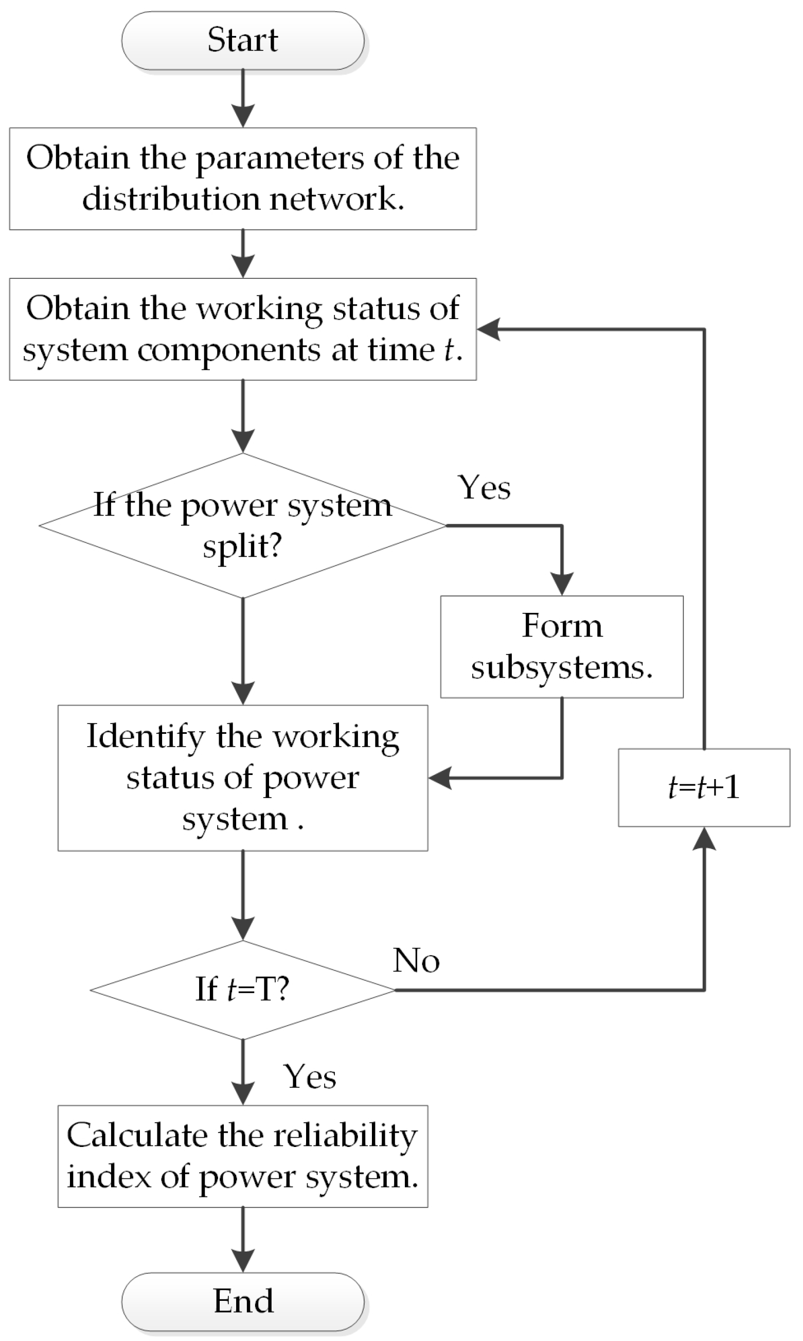
To obtain the optimal site of energy storage, it is necessary to establish the reliability model of the distribution system integrated with the energy storage. In this paper, the Monte Carlo method is utilized to identify the system reliability. The flowchart of the energy storage installed location optimization configuration is shown in Figure 2.
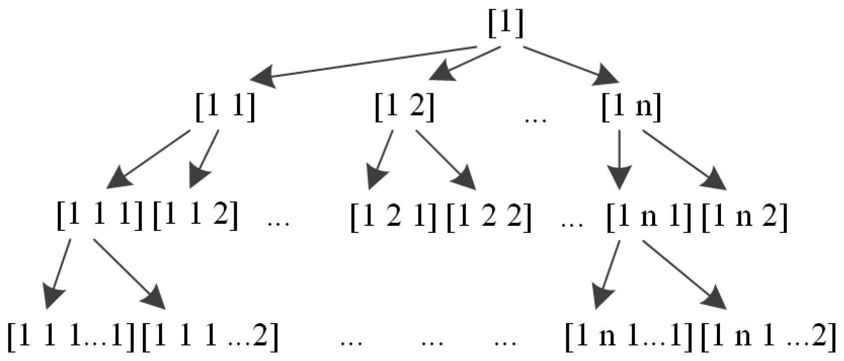
System splitting detection and identification are an important step for the calculation model. The depth-first search algorithm is used to detect and identify the system splitting. At first, we should choose one node in the distribution network to begin searching. Then, a depth-first traversal is given in turn from the adjacent nodes that are not accessed, until all the nodes that have the same path with the node are accessed in this graph. If there are nodes not accessed in the graph, we should choose one of them, and repeat the previous steps until all the nodes in the network are accessed. Based on this method, we can traverse the distribution system after failure occurs. If the distribution system graph is a connected graph, all the nodes can be accessed from an arbitrary node in the graph. Otherwise, this access is impossible to achieve. Moreover, to reduce the computational burden for optimization, a search tree algorithm is used to solve the energy storage location problem. The algorithm is shown in Figure 3.
The structure of the search tree is shown in Figure 3. The nodes in the search tree express the locations of the energy storage system, and it can be indicated by an eigenvector. Each eigenvector contains n characteristic variables. The first n − 1 characteristic variables of the node are the same as the characteristic variables of its parent node. The last characteristic variable of the node is the number of nodes that have the same parent node. The eigenvector reflects the relationship of the nodes.
The reliability of the distribution network with the energy storage installed at the root node is defined as the reference value of the reliability. Then, according to the last variable, the characteristic vectors with the same dimension are sorted in descending order. The nodes with the same property dimensions and the same former n − 1 value are grouped. From the largest dimension of the vector group, the reliability of the corresponding system of each set of vectors is calculated. Then, the maximum ReliabilityIndex of the node in each node group is obtained, and we can compare the value of ReliabilityIndexmin with the value of the next node group. If the value of ReliabilityIndexmin is larger than the next node group, keep on searching; otherwise, the will be the system reliability in this node group. As mentioned before, we can then search for the parent node of the group and calculate the system reliability. Finally, we can obtain the optimal system reliability and energy storage installation location.
3.3. Solution Process
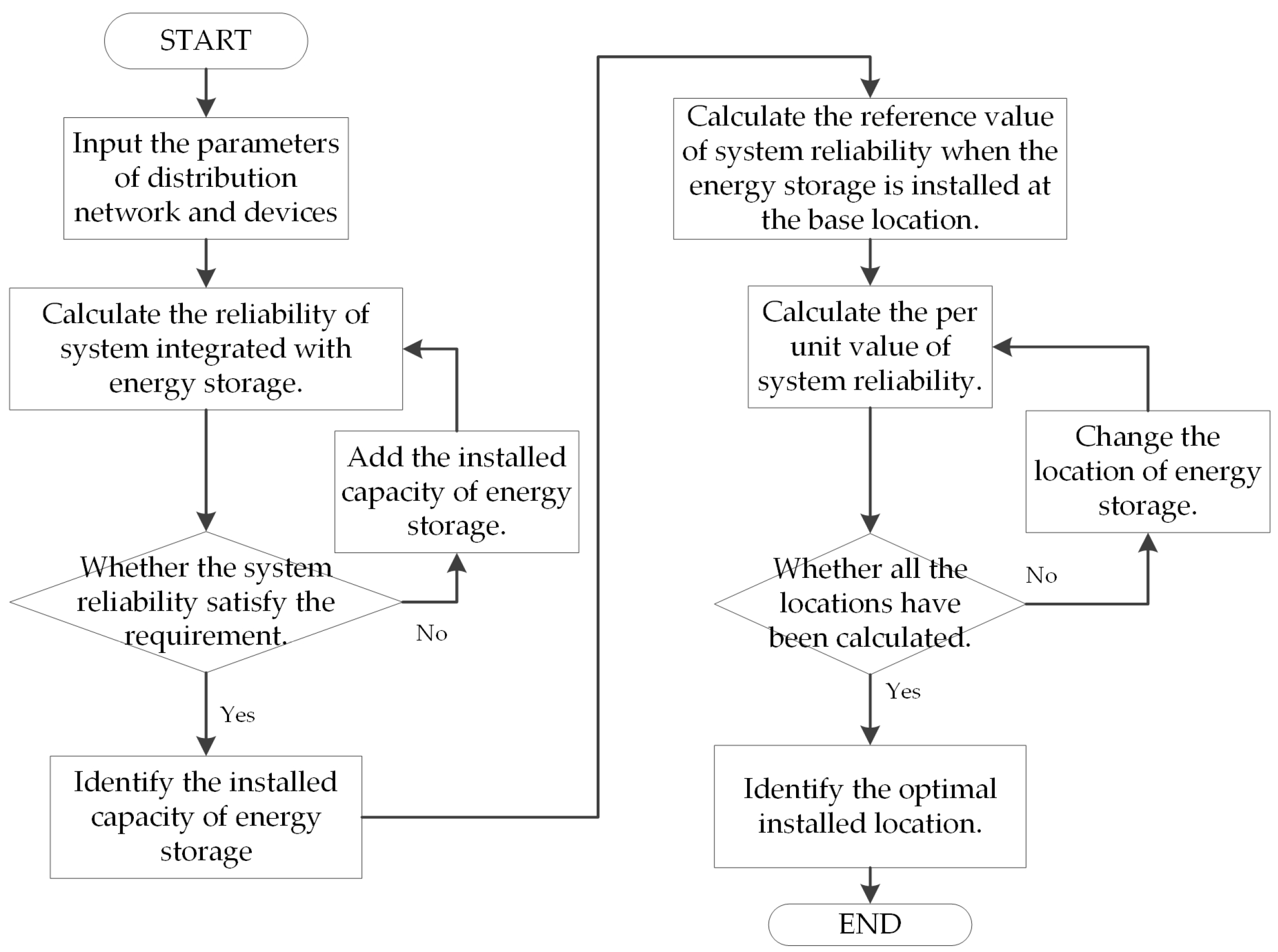
In the bi-level programming of the energy storage system configuration, the upper-level problem is the optimization of the energy storage system location in the distribution network, and the lower-level problem is the optimization of the capacity configuration. According to the optimization model presented in the previous section, the flowchart of the proposed method is shown in Figure 4.
Step 1. Obtain the distribution network structure and grid data. The system data include the conventional generator output power data, reliability data, wind turbine data, wind speed data, energy storage data and reliability requirement;
Step 2. Calculate the reliability of the distribution network without energy storage;
Step 3. Add the unit installed capacity of energy storage;
Step 4. Calculate the reliability index of distribution network integration with the energy storage system;
Step 5. If the reliability index meets the system reliability requirement, stop increasing the energy storage capacity, and the value of the capacity is the installed capacity of energy storage. Otherwise, go to step 3;
Step 6. Group the potential installation sites of energy storage and form the node group;
Step 7. Sort the node group according to the dimension of the node vector;
Step 8. Calculate the system reliability for each energy storage installation site scheme using the search tree algorithm;
Step 9. Determine whether all the reliability indices of the distribution network for the potential energy storage installation location are calculated;
Step 10. Obtain the optimal installation site of the energy storage system.
4. Numerical Applications
4.1. System Description and Basic Data
In this paper, RBTD-BUS 6 is applied to verify the validity of the optimization model and method proposed in this paper. The single line diagram of the test system is shown in Figure 5. In this distribution network, the installed capacity of the conventional generator is 300 MW. The IEEE-RTS [38] load demand distribution is utilized in this study, and the peak load is 550 MW. The hourly wind speed data are taken from the historical wind speed data of Prince Albert in Canada, from years 2001 to 2012 [39]. In addition, the conventional generator availability is generated using a Monte-Carlo simulation. The system includes 51 nodes and 40 load nodes. The distribution network is connected to the main grid by connection lines through node 35. Figure 5 demonstrates the single line diagram of the distribution network.
In the studies, the energy storage devices are centrally installed in the distribution network. The proposed model is implemented in IBM ILOG CPLEX 12.2 on a Dell M4600 laptop with Intel Core i7-2820QM CPU 2.30 GHz RAM 8 GB.
In the application, the candidate location nodes for the energy storage system are finite, and the installation of energy storage is centralized. In the power system planning, the installation location of the energy storage system is unverified. This paper analyzes the application of energy storage by the following four cases in detail to demonstrate that the improvement of system reliability differs when the energy storage system is installed at different locations. Four cases are designed, and the comparison is discussed in the following section.
- -
- Case 1: The energy storage devices are located near the distributed generation (DG); in this case, it is located at the wind power generation. This installation point is widely located in the energy storage system allocation. Because wind power is the main intermittent source in the distribution grid, the energy storage system near this point can have a relatively high likelihood of reliability improvement from the intermittent sources aspect.
- -
- Case 2: The energy storage system is installed at load point 30 (LP30). This installation point is the end of the distribution system. The energy storage system at this bus may have a relatively high likelihood of reliability improvement of the end of the distribution system.
- -
- Case 3: The energy storage system is installed at load point 40 (LP40). This installation point is also the end of the distribution system (just like the load point 30); however, these two installation points have different electrical distances from the wind power. The comparison results can tell the energy storage system planner the influence of the electrical distance from the wind power on the reliability improvement of the energy storage system.
- -
- Case 4: The energy storage system is installed at line point 45 (LP45). This installation point is a reference point for the other cases.
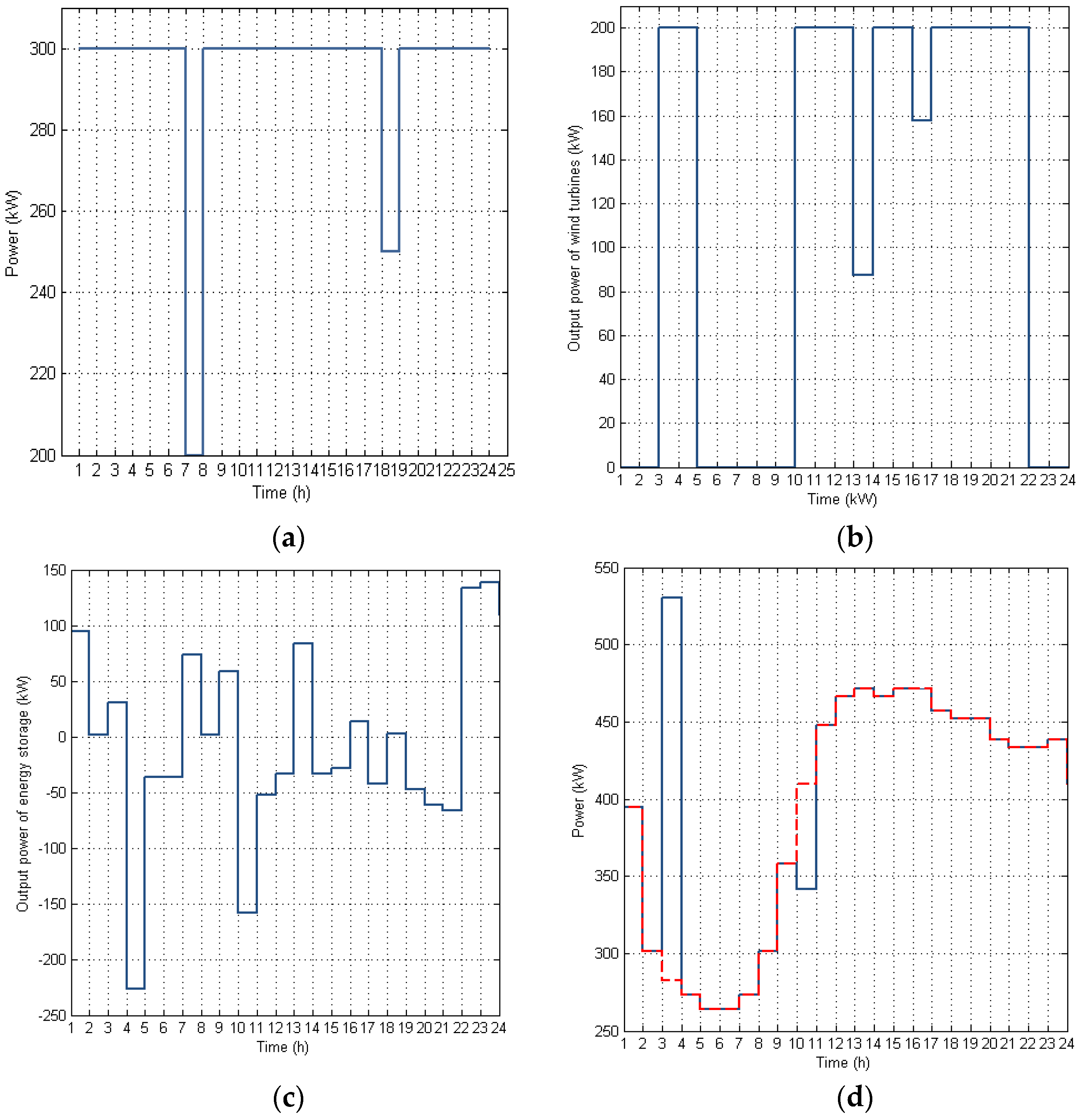
Figure 6 indicates the daily output power of the generators in distribution network. Figure 6b shows the daily output of wind generation. The power system daily load profile was modeled with a single-step model, and the daily load profile is shown in Figure 6c. Figure 6d shows the hourly load profile pattern, and only the active load demand is given in the figure. In the period from 9:00 to 23:00, there is high load demand, which constitutes the daily peak load hours. During the period from 2:00 to 7:00, there is a lower load demand.
In this case, as foreseeable, the energy storage charge power occurs when the available capacity of distribution network is lower than the load demand; otherwise, it is the energy storage discharge power. As Figure 6 shows, from 1:00 to 10:00, the output power of the wind power generator is less and the wind power generator is in the outage state. Although the load demand is less during this period, the output power of energy storage is large enough to fill the gap caused by the wind power. Therefore, the energy storage discharges power during the period. Furthermore, during the period of 12:00–22:00, the output power of the wind turbine works at the rated operating condition most of the time. During this period, the wind power can supply a greater load demand; although the load demand is high, the energy storage system works at the charging power status.
The output power of the energy storage system of the four cases will be illustrated below, respectively. Figure 7 indicates the daily output power of energy storage system at different installation sites. Figure 7a–d shows the daily output power of the energy storage system when the energy storage is located at LP30, LP40, LP45 and DG, respectively.
After the further analysis of the results of the presented method, we find that the energy storage is charging power during the period of 11:00–22:00 and discharging power during the period of 7:00–11:00. The change in energy stored in the energy storage is limited to the maximum energy stored in the energy storage and the depth of discharge. From Figure 7, comparing the output power of the energy storage installed at different sites, we find that the charge and discharge time of the energy storage have a consistent trend. The output power of the energy storage located at LP40 is more than the others, and when it is located at DG, the output power is more than at LP45 and LP30. The energy storage located at LP40 improves the system reliability more effectively. Furthermore, the output power of energy storage at LP30 and LP45 has the same power curve in the chosen 24 h. Therefore, when the energy storage is installed at the end of the distribution network, the energy storage will have a greater contribution to system reliability.
4.2. Sensitive Analysis
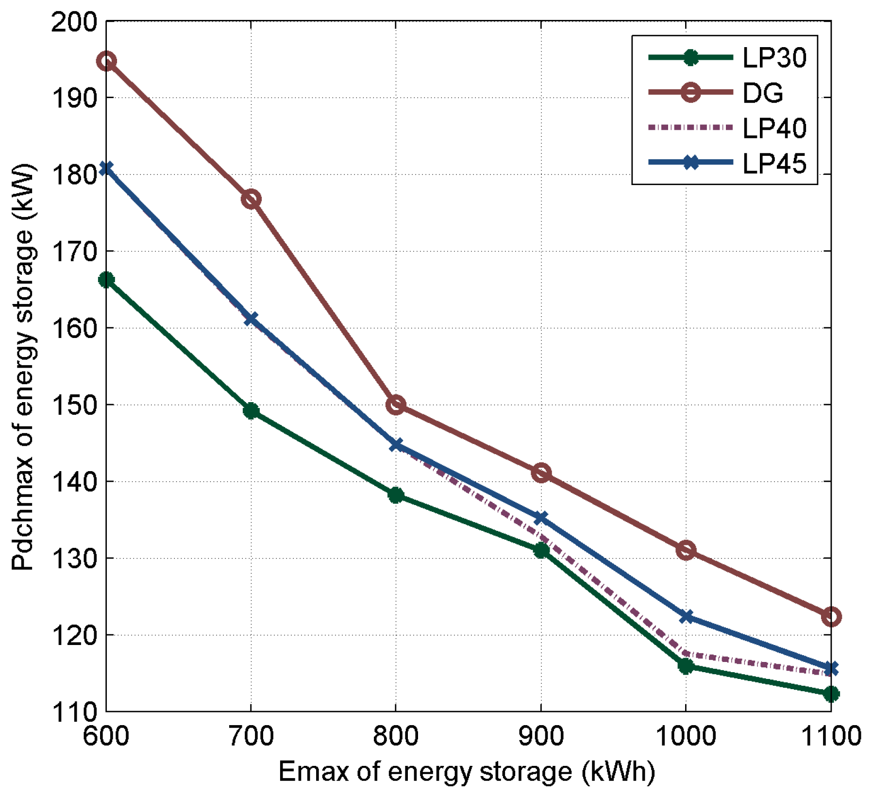
4.2.1. The Effect of Emax of Energy Storage
The effect of Emax of the energy storage system installed at different positions to system reliability is shown in Figure 8. To maintain the same reliability, the changing trends of against the of energy storage system are the same. With the increasing of Emax of the energy storage, the installed Pdchmax can be reduced, until the Emax of energy storage increases to 1000 kWh, when the reduction is less pronounced. The increase of Emax and may improve the available capacity of energy storage under the same reliability index. Therefore, to maintain the same system reliability, and are both positively associated with system reliability. Thus, the two factors are inversely correlated when the system reliability is determined. However, with regard to the same , a different is necessary for the different installed sites of energy storage. Furhtermore, Figure 8 shows that for a given , the desired increases when the installed locations are LP30, LP40, LP45 and DG, respectively. The desired is close when the energy storage is installed at LP40 and LP45, and is higher than that installed at LP30. The relation between the installed locations and is irrelevant to of the energy storage, but the effect decreases with an increasing .
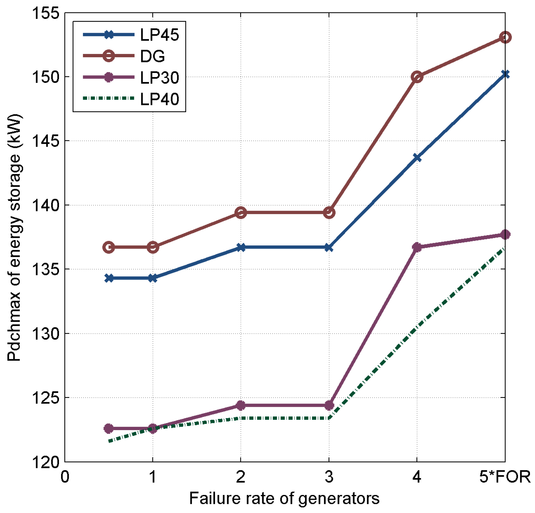
4.2.2. Effect of the Failure Rate of Generators
Figure 9 shows the effect of the failure rate of conventional generators on the installed of energy storage, under a certain system reliability. The most immediate conclusion is that the choice of the energy storage system installation location can have a significant impact on the desired installed . For the energy storage system, the highest can be up to nearly 15% higher than the lowest for the installed location. Furthermore, when the failure rate of conventional generators is determined, to achieve the certain system reliability, the installed values of energy storage at different locations are different. The desired installed increases at LP40, LP30, LP45 and DG, respectively. The desired is close when the energy storage is installed at LP30 and LP40, and is lower than that when the installation is at LP45 and DG. The relation between the installed locations and is irrelevant to the failure rate of conventional generators. Obviously, the changing trend of the installed of energy storage at different locations against the failure rate of conventional generators under a certain system reliability is the same. The installed of energy storage at different locations increases with an increasing failure rate of conventional generators in the distribution network because the potential reliability risk increases with the increasing failure rate of conventional generators under a certain system reliability. As the peak load of energy storage shifts, the system reliability will be effectively improved by the energy storage, and the increasing installed of energy storage will compensate for the potential reliability risk of the distribution network.
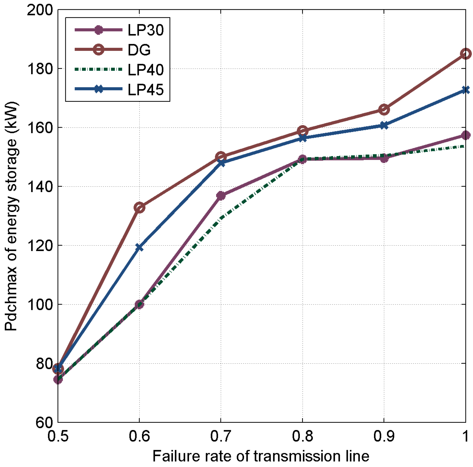
4.2.3. Effect of the Failure Rate of the Transmission Line
Figure 10 shows the effect of the transmission line reliability on the installed of energy storage under a certain system reliability. In the study, the failure rate is utilized to model the reliability of transmission lines. Therefore, the influence of the failure rate on the installed of energy storage is studied. From Figure 10, under a certain system reliability, it can be noted that the variation trend of the desired of the four different installed locations (i.e., LP40, LP30, LP45 and DG) are consistent. Moreover, the installed of energy storage increases with the failure rate of the transmission line. With the increasing of the failure rate, the system reliability decreases. Therefore, the system reliability risk brought by the increasing failure rate of transmission lines should be compensated by other factors. The energy storage system can effectively improve the system reliability by peak load shifting, and the increase in of energy storage well compensates for the system reliability risk. Thus, of energy storage will increase with an increasing failure rate to maintain the certain system reliability. When the transmission failure rate is determined, there is no larger difference between the different installed locations when the failure rate of transmission line is 0.5; the desired installed energy storage at different locations becomes different when the failure rate of the transmission line is more than 0.6. The desired installed Pdchmax increases at LP40, LP30, LP45 and DG, respectively. The desired value is close when the energy storage is installed at LP30 and LP40, and is lower than that when the installation occurs at LP45 and DG. The relation between the installed locations is irrelevant to the failure rate of the transmission lines.
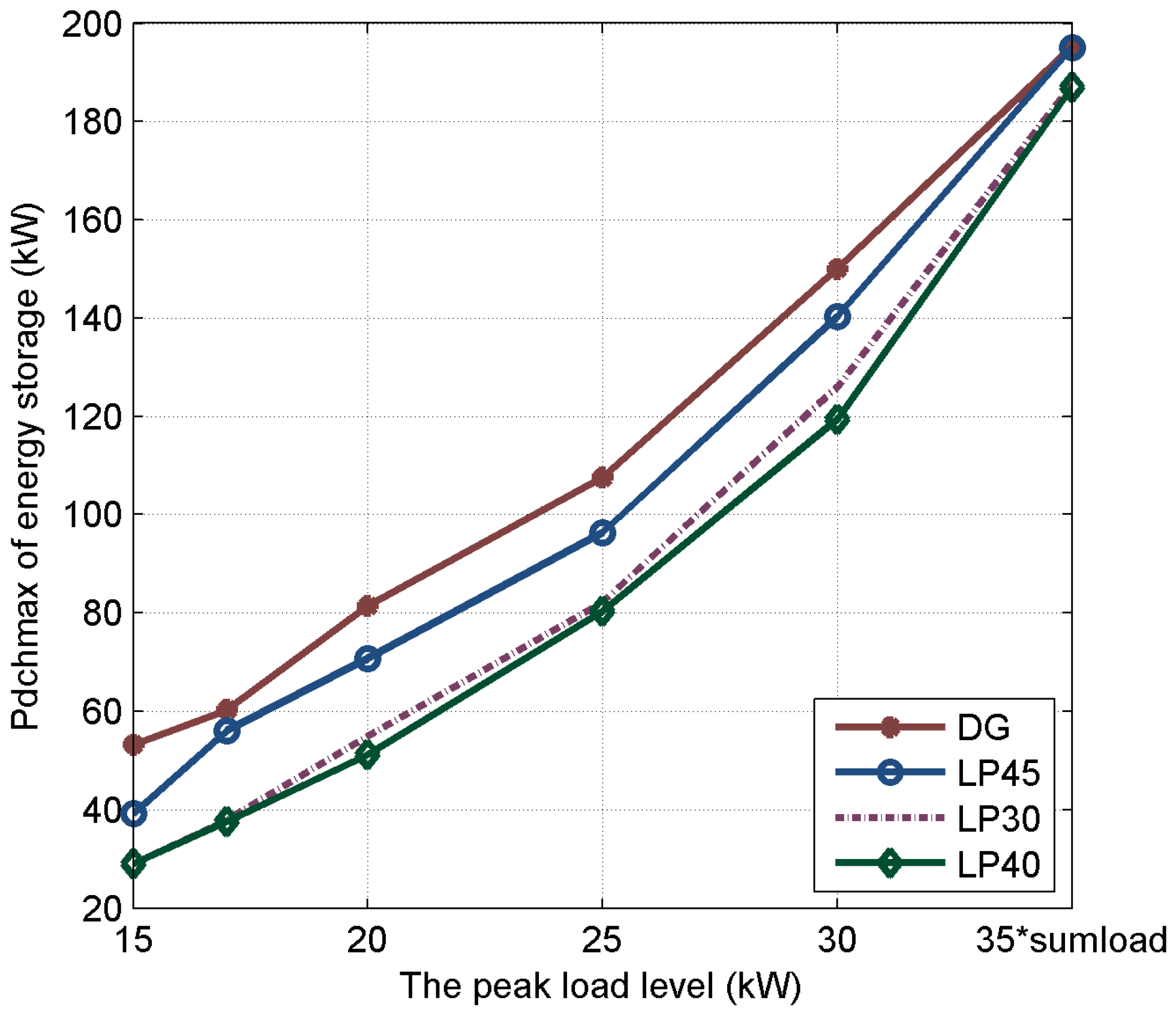
4.2.4. Effect of the Load
Figure 11 describes the relationship between the load level and the installed of energy storage. In Figure 11, with a certain system reliability, the changing trend of the installed of energy storage against the load level is the same, and the installed of energy storage increases with an increasing load level. The ability of the power supply in the original system to satisfy the load demand will decrease with an increasing load level, and the system reliability decreases. To maintain the reliability of the original system, the installed of energy storage should be added to improve the ability of peak load shifting of the energy storage, and improve the system reliability. When the load demand is determined, the desired installed of energy storage differs at the various locations. The desired installed increases at LP40, LP30, LP45 and DG, respectively. The desired is close when the energy storage is installed at LP30 and LP40, and is lower than that when the installation occurs at LP45 and DG. The relation between the installed locations and is irrelevant to the load demand of the distribution network.
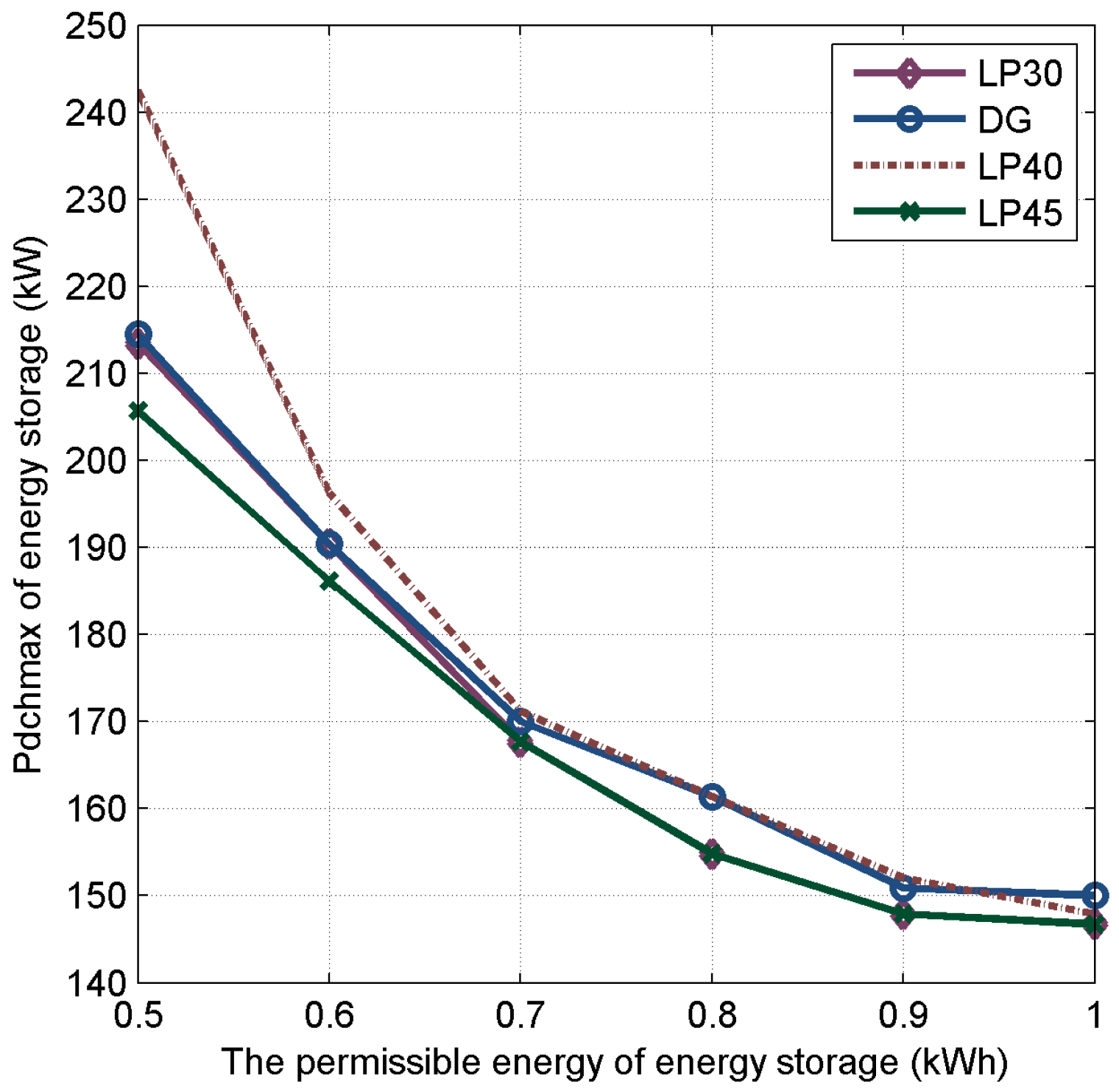
4.2.5. Effect of the Maximum Energy Stored in Energy Storage
The desired installed as a function of state of charge (SOC) under certain system reliability is shown in Figure 12 for one of the test systems. SOC and of energy storage are the attributes of the energy storage system. In Figure 12, the desired installed of energy storage decreases with the increasing of SOC. SOC and are the attributes of the energy storage, and the ability of peak load shifting of energy storage will be improved by the increase in . Therefore, to maintain the system reliability, the desired installed decreases with increasing SOC. Although the differences are small, a high SOC value can be chosen for a study that is intended to show small differences of different energy storage system installation locations, whereas a low SOC can be used to emphasize the difference. When the SOC of energy storage system is determined, the desired installed of energy storage differs at the various locations. The desired installed increases at LP45, LP30, DG and LP40, respectively. The desired is close when the energy storage is installed at DG and LP30, and is higher than that when the installation occurs at LP45 lower than LP40. The desired installed goes from <170 for the cases, to values >0.7 of SOC. The relation between the installed locations and is irrelevant to the SOC of energy storage. Such arbitrariness is not good for the credibility of the results, and it seems more preferable to select the installation location.
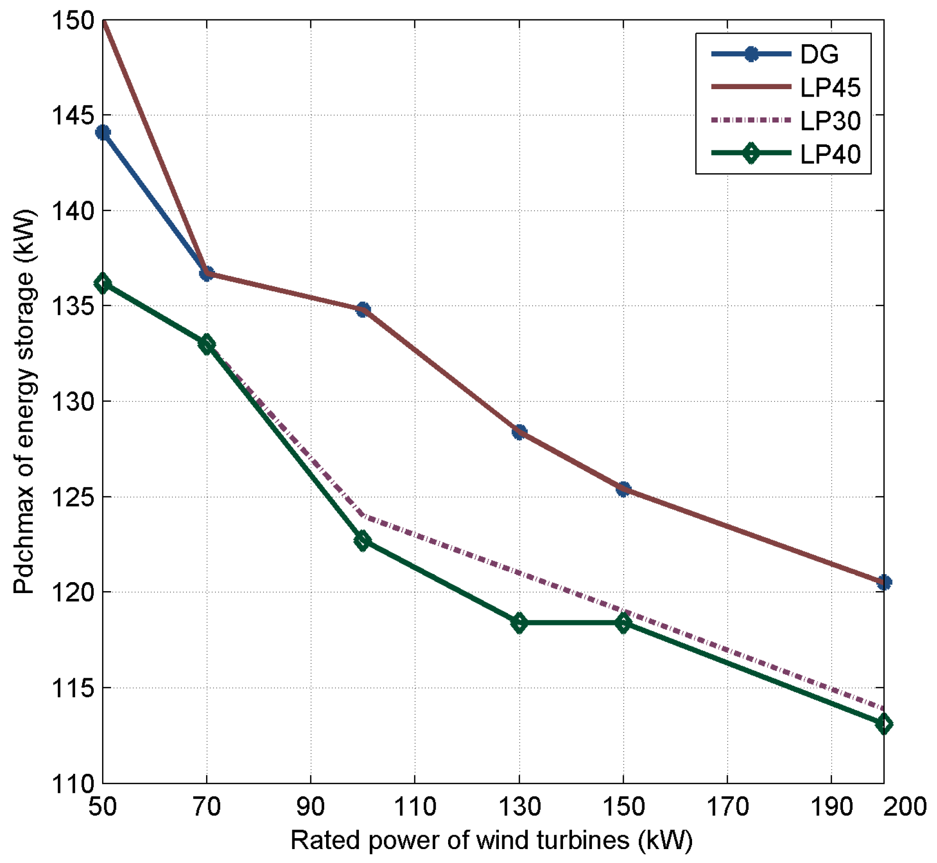
4.2.6. Effect of the Rated Power of Wind Turbines
Figure 13 shows the relationship between the installed of energy storage and the installation capacity of wind power generators under a certain system reliability. In Figure 13, when the system reliability is determined, the desired of energy storage decreases with the increasing of the capacity of wind turbines. There is definitely a trend toward a higher desired installed for systems with a low installation capacity of wind power generators with a certain system reliability. The trend is even clearer in Figure 8, which shows both the installed capacity of wind power generators and energy storage as an inverse correlated function of the desired installed . As one of the power supplies, the wind power generator satisfies parts of the load demand. Thus, wind power will supply a greater load demand with an increasing wind turbine capacity. The desired installed increases at LP40, LP30, DG and LP45, respectively. The desired is close when the energy storage is installed at DG and LP45, and is higher than that when the installation occurs at LP40 and LP30. The relation between the installed locations and is irrelevant to the capacity of the wind power generator.
4.2.7. Comparison of Centralized and Decentralized Allocated Energy Storage Devices
The above sensitive analysis is given when the energy storage devices are considered centralized. However, the energy storage devices can also be allocated as decentralized. To compare the effect of centralized and decentralized allocated energy storage devices on system reliability, several allocation schemes are given. Moreover, the installed Pdchmax of energy storage when the energy storage devices are considered centralized and decentralized is presented in Table 1. Considering centralized and decentralized installation of energy storage, reliability improvement will increase with an increasing installation capacity of energy storage. Compared with the centralized installation, the decentralized installation of energy storage cannot effectively improve the reliability. The effect of the decentralized allocation scheme on system reliability is related to the grid structure.
4.3. Case Study
NA Island is located at GD province, China. The geographical position of this island is shown in Figure 14, and the single line diagram of the NA island power system is shown in Figure 15. There are approximately 70,000 inhabitants living on the NA Island. The island has abundant wind resources, and the local consumers’ energy demand is supplied by the NA Island grid. The grid structure of NA Island is a simple unidirectional radial network. The yearly peak load of system is 1500 kVA. The installation capacity of the conventional generator is 600 kW. NA Island is located on the southwest side of Taiwan Strait flared between Fujian and Guangdong, near the sea. Because of the throat effect of the channel and the dynamic uplift of the protrusion causing by the upwind terrain, NA Island has a rich wind resources. The total installed capacity of wind power generator at NA Island is 3100 kW. To maintain the supply-demand balance of the power system, it is considered to allocate the energy storage system to peak load shifting in this distribution network. The energy storage will charge the surplus power when the wind speed is high, and discharge power to supply the load demand when the wind speed is low.
The method is applied to the allocation of energy storage on the island, and the energy storage system is planned to be located at the Qingao (QA) wind farm, Niutouling (NTL) wind farm, Yunao (YA) wind farm or Guoshan (GS) line, respectively. The reliability assessment results of the energy storage allocation are listed in Table 1.
From the analysis of Table 2, it follows that the increased system reliability is related to the increase in the installed Pdchmax of energy storage at any of the locations listed in the table. Moreover, the degree of improvement of each allocation scheme is almost the same. Notably, with the same installed Pdchmax of energy storage, the system reliability differs when the energy storage is located at different nodes, and when located at YA, the energy storage will better improve the system reliability.
5. Conclusions
The rapid growth of wind power penetration in a distribution system poses challenges to the distribution system reliability. A reasonable energy storage control strategy, wind power control strategy and load demand side management can effectively alleviate the adverse effects caused by the intermittence of wind power. Among these methods, a reasonable allocation of energy storage systems in a distribution system will effectively improve the distribution system reliability.
The energy storage configuration affects the system operation reliability and maintenance. Therefore, not only the storage device owner focuses on the rational allocation of energy storage; for power system operators, the optimization allocation of energy storage is also important. This paper investigated the optimization allocation problem of an energy storage system in a distribution network. Based on existing energy storage allocation experiences, this paper presented a bi-level programming assessment model to solve the problem of optimal capacity and installation location allocation of energy storage under certain reliability requirements. The solution scheme based on the model is presented to determine the optimal installation location of the energy system under a certain system reliability. Compared with the configuration optimization method aiming to obtain the lowest cost of energy storage, the optimization method presented in this paper provides a practical solution to quantitatively evaluate the capacity and location optimization of an energy storage system. This method provides an intuitive basis for planners to allocate the location and capacity of energy storage. Case studies show that the different site of energy storage will yield different contributions to the system reliability, and the influence of different factors on the optimization results is analyzed by a sensitivity analysis. The main conclusions of this paper are as follows:
First, an energy storage system can effectively improve distribution system reliability. This paper presented a novel optimization method for the capacity and installation site configuration of energy storage to provide a theoretical basis and practical method for the rational allocation of energy storage in a distribution network.
Second, a search tree method was used to effectively solve the location selection problem in energy storage planning, and identified the installation position of energy storage. The algorithm greatly minimizes the calculation amount.
Third, the sensitivity analysis of the proposed configuration model has been given, and this paper provides a reasonable and effective basis and a practical way to improve the system reliability in a distribution network. Remarkably, with installation at the end of the distribution network, the smallest energy storage capacity would be necessary to satisfy certain reliability requirements. A reasonable siting allocation of an energy storage system can effectively reduce the installed energy storage capacity.
Future work will address the application of a bi-level programming method to the optimal allocation of the device types and parameters of the energy storage system. Moreover, the algorithm will also be studied to reduce the computational burden of optimization.
Acknowledgments
This work was supported by the Key Project of Chinese National Programs for Research and Development (No. 2016YFB0900100).
Author Contributions
All authors contributed to this work. Nian Shi performed the numerical and theoretical modeling and executed the numerical work. Yi Luo performed the theoretical and experimental modeling.
Conflicts of Interest
The authors declare no conflict of interest.
Nomenclature
| Parameters and Variables: | |
| Installed node number of the energy storage | |
| Installed capacity of the energy storage | |
| Node number of the potential installed location of the energy storage | |
| T | Sampling time period (h) |
| Available power in the distribution network (kW) | |
| Load demand at hour t (kW) | |
| Conventional Generator Parameters: | |
| Number of conventional generators | |
| Output power of the conventional generator (kW) | |
| Minimum active power of the conventional generator (kW) | |
| Maximum active power of the conventional generator (kW) | |
| Minimum reactive power of the conventional generator (kW) | |
| Maximum reactive power of the conventional generator (kW) | |
| Working status of the conventional generator | |
| Wind Power Model Parameters: | |
| v | Wind speed (m/s) |
| Pr | Rated output power of the wind turbines (kW) |
| Cin | Parameter related to the cut-in wind speed of the wind turbines |
| Crate | Parameter related to the rated wind speed of the wind turbines |
| Cout | Parameter related to the cut-out wind speed of the wind turbines |
| C1, C2, C3 | Parameters related to the wind turbines |
| Number of wind turbines | |
| PWT,j | Output power of the wind turbine (kW) |
| Rated output power of the jth wind turbine (kW) | |
| Wind power curtailment (kW) | |
| Energy Storage Model Parameters: | |
| Number of energy storages | |
| Output power of the energy storage (kW) | |
| Power of the energy storage (kW) | |
| Maximum discharge power of the energy storage (kW) | |
| Maximum charging power of the energy storage (kW) | |
| Energy stored in the energy storage at hour t (kWh) | |
| Emin | Lower limit energy stored in the energy storage (kWh) |
| Emax | Upper limit energy stored in the energy storage (kWh) |
| PAvailable(t) | Available power of the energy storage at hour t (kW) |
| SOC | State of charge of the energy storage (kW) |
| Minimum SOC of the kth energy storage (kW) | |
| Maximum SOC of the kth energy storage (kW) | |
| Maximum power in the energy storage (kW) | |
References
- Shi, N.; Luo, Y. Energy storage system sizing based on a reliability assessment of power systems integrated with wind power. Sustainability 2017, 9, 395. [Google Scholar] [CrossRef]
- Zhang, Y.X.; Zhao, Y.D.; Luo, F.J.; Zheng, Y.; Meng, K.; Kit, P.W. Optimal allocation of battery energy storage systems in distribution networks with high wind power penetration. IET Renew. Power Gener. 2016, 10, 1105–1113. [Google Scholar] [CrossRef]
- Niu, Y.; Surya, S. Determining optimal energy storage size to mitigate intra-hour wind power variability. In Proceedings of the Industry Applications Society Meeting, Dallas, TX, USA, 18–22 October 2015. [Google Scholar]
- Pavithra, H.; Munther, D. Optimal management and sizing of energy storage under dynamic pricing for the efficient integration of renewable energy. IEEE Trans. Power Syst. 2015, 30, 1164–1181. [Google Scholar]
- Hamed, V.H.; Saeed, L. Spatiotemporal modeling of wind generation for optimal energy storage sizing. IEEE Trans. Sustain. Energy 2015, 6, 113–121. [Google Scholar]
- Ted, K.A.B.; Alex, Y.; Annette, V.J.; Zuan, Z.Y.; Hannes, M.H.; Douglas, A.H. Optimal energy storage sizing and control for wind power applications. IEEE Trans. Sustain. Energy 2011, 2, 69–77. [Google Scholar]
- Sahban, W.A.; Luis, F.O. Optimal sizing and control of energy storage in wind power-rich distribution networks. IEEE Trans. Power Syst. 2016, 31, 2004–2013. [Google Scholar]
- Guido, C.; Gianni, C.; Susanna, M.; Fabio, M.; Fabrizio, P.; Daniela, P. Optimal integration of distributed energy storage devices in smart grids. IEEE Trans. Smart Grid 2013, 4, 985–995. [Google Scholar]
- Ghofrani, M.; Arabali, A.; Etezadi-Amoli, M.; Sami, M.F. A framework for optimal placement of energy storage units within a power system with high wind penetration. IEEE Trans. Sustain. Energy 2013, 4, 434–442. [Google Scholar] [CrossRef]
- Sedghi, M.; Aliakbar-Golkar, M.; Haghifam, M. Distribution network expansion considering distributed generation and storage units using modified PSO algorithm. Int. J. Electr. Power Energy Syst. 2013, 52, 221–230. [Google Scholar] [CrossRef]
- Zheng, Y.; Dong, Z.Y.; Luo, F.J.; Meng, K.; Qiu, J.; Wong, K.P. Optimal allocation of energy storage system for risk mitigation of DISCOs with high renewable penetrations. IEEE Trans. Power Syst. 2014, 29, 212–220. [Google Scholar] [CrossRef]
- Atwa, Y.; El-Saadany, E. Optimal allocation of ESS in distribution systems with a high penetration of wind energy. IEEE Trans. Power Syst. 2010, 25, 1815–1822. [Google Scholar] [CrossRef]
- Akhavan-Hejazi, H.; Mohsenian-Rad, H. Optimal operation of independent storage systems in energy and reserve markets with high wind penetration. IEEE Trans. Smart Grid 2014, 5, 1088–1097. [Google Scholar] [CrossRef]
- Zheng, L.; Hu, W.; Lu, Q.; Min, Y. Optimal energy storage system allocation and operation for improving wind power penetration. IET Gener. Transm. Distrib. 2015, 9, 2672–2678. [Google Scholar] [CrossRef]
- Farhad, F.; Mostafa, N.; Gholam, H.R.; Seyed, H.H.; Aref, D. The value of energy storage in optimal non-firm wind capacity connection to power systems. Renew. Energy 2014, 64, 34–42. [Google Scholar]
- Khani, H.; Zadeh, M.R.D.; Hajimiragha, A.H. Transmission congestion relief using privately owned large-scale energy storage systems in a competitive electricity market. IEEE Trans. Power Syst. 2016, 31, 1449–1458. [Google Scholar] [CrossRef]
- Jamian, J.J.; Mustafa, M.W.; Mokhlis, H.; Baharudin, M.A. Simulation study on optimal placement and sizing of battery switching station units using Artificial Bee Colony algorithm. Int. J. Electr. Power Energy Syst. 2014, 55, 592–601. [Google Scholar] [CrossRef]
- Bahman, B.F.; Rasoul, A.A. Optimal sizing of battery energy storage for micro-grid operation management using a new improved bat algorithm. Int. J. Electr. Power Energy Syst. 2014, 56, 42–54. [Google Scholar] [CrossRef]
- Mostafa, N.; Rachid, C.; Mario, P. Optimal allocation of dispersed energy storage systems in active distribution networks for energy balance and grid support. IEEE Trans. Power Syst. 2014, 29, 2300–2310. [Google Scholar]
- Mohammad, R.A.; Hajar, A. A new approach for optimal sizing of battery energy storage system for primary frequency control of islanded microgrid. Int. J. Electr. Power Energy Syst. 2014, 54, 325–333. [Google Scholar]
- Danny, P.; Marko, A.; Predrag, D.; Goran, S. Whole-systems assessment of the value of energy storage in low-carbon electricity systems. IEEE Trans. Smart Grid 2014, 5, 1098–1109. [Google Scholar]
- Han, X.; Ji, T.; Zhao, Z.; Zhang, H. Economic evaluation of batteries planning in energy storage power stations for load shifting. Renew. Energy 2015, 78, 643–647. [Google Scholar] [CrossRef]
- Francesco, M.; Guangya, Y.; Chresten, T.; Jacob, Ø.; Esben, L. A decentralized storage strategy for residential feeders with photovoltaics. IEEE Trans. Smart Grid 2014, 5, 974–981. [Google Scholar]
- Ahmed, S.A.A.; Tarek, H.M.E.F.; Magdy, M.A.S. Optimal ESS allocation and load shedding for improving distribution system reliability. IEEE Trans. Smart Grid 2014, 5, 2339–2349. [Google Scholar]
- Hrvoje, P.; Yishen, W.; Ting, Q.; Yury, D.; Daniel, S.K. Near-optimal method for siting and sizing of distributed storage in a transmission network. IEEE Trans. Power Syst. 2015, 30, 2288–2300. [Google Scholar]
- Sonja, W.; Dennice, F.G. Optimizing storage siting, sizing, and technology portfolios in transmission- constrained networks. IEEE Trans. Power Syst. 2015, 30, 3304–3313. [Google Scholar]
- Adarsh, N.; Raja, A. Design and strategy for the deployment of energy storage systems in a distribution feeder with penetration of renewable resources. IEEE Trans. Sustain. Energy 2015, 6, 1085–1092. [Google Scholar]
- Yue, D.; You, F. Stackelberg-game-based modeling and optimization for supply chain design and operations: A mixed integer bilevel programming framework. Comput. Chem. Eng. 2016. [Google Scholar] [CrossRef]
- Ghazal, A.; Ginger, Y.K.; Manish, V. A toll-based bi-level programming approach to managing hazardous materials shipments over an intermodal transportation network. Transp. Res. D Transp. Environ. 2016, 47, 208–221. [Google Scholar]
- Guo, Z.; Zhang, D.; Leung, S.Y.S.; Shi, L. A bi-level evolutionary optimization approach for integrated production and transportation scheduling. Appl. Soft Comput. 2016, 42, 215–228. [Google Scholar] [CrossRef]
- Apurba, K.N.; Hugh, R.M.; Satish, V. Interdicting attack graphs to protect organizations from cyber attacks: A bi-level defender–attacker model. Comput. Oper. Res. 2016, 75, 118–131. [Google Scholar]
- Bahramara, S.; Parsa, M.M.; Haghifam, M.R. A bi-level optimization model for operation of distribution networks with micro-grids. Int. J. Electr. Power Energy Syst. 2016, 82, 169–178. [Google Scholar] [CrossRef]
- Ilan, M.; Sonja, W.; Tomás, G.S.R. Retail pricing: A bilevel program for PEV aggregator decisions using indirect load control. IEEE Trans. Power Syst. 2016, 31, 464–473. [Google Scholar]
- Ricardo, F.B.; José, M.A.; Natalia, A. A unified bilevel programming framework for price-based market clearing under marginal pricing. IEEE Trans. Power Syst. 2012, 27, 517–525. [Google Scholar]
- Marcos, J.R.; Jesus, M.L.L.; Javier, C. Bilevel approach for optimal location and contract pricing of distributed generation in radial distribution systems using mixed-integer linear programming. IET Gener. Transm. Distrib. 2013, 7, 724–734. [Google Scholar]
- Faruk, U.; Engin, K.; Arne, H.N. MILP Approach for bilevel transmission and reactive power planning considering wind curtailment. IEEE Trans. Power Syst. 2017, 32, 652–661. [Google Scholar]
- Almeida, K.C.; Senna, F.S. Optimal active-reactive power dispatch under competition via bilevel programming. IEEE Trans. Power Syst. 2011, 26, 2345–2354. [Google Scholar] [CrossRef]
- RTS Task Force of the APM Subcommittee. IEEE reliability test systems. IEEE Trans. Power Appar. Syst. PAS 1979, 98, 2047–2054. [Google Scholar]
- Historical Climate Data. Available online: http://climate.weather.gc.ca (accessed on 5 June 2016).
Figure 1.
Diagram of a distribution network integrated with an energy storage system.

Figure 2.
Flowchart of the energy storage installed location optimization configuration.

Figure 3.
Structure of the search tree algorithm.

Figure 4.
Flowchart of the bi-level programming of the energy storage system.

Figure 5.
Single line diagram of test system.

Figure 6.
Daily power of the devices in the distribution network. (a) Daily output power of the fuel generator; (b) daily wind power; (c) output power of energy storage at LP30; (d) daily load demand and available capacity.
Figure 6.
Daily power of the devices in the distribution network. (a) Daily output power of the fuel generator; (b) daily wind power; (c) output power of energy storage at LP30; (d) daily load demand and available capacity.

Figure 7.
Daily output power of energy storage located at DG, LP30, LP40 and LP45, respectively. (a) Daily output power of energy storage at DG; (b) daily output power of energy storage at LP30; (c) daily output power of energy storage at LP40; (d) daily output power of energy storage at LP45.
Figure 7.
Daily output power of energy storage located at DG, LP30, LP40 and LP45, respectively. (a) Daily output power of energy storage at DG; (b) daily output power of energy storage at LP30; (c) daily output power of energy storage at LP40; (d) daily output power of energy storage at LP45.

Figure 8.
Change in Pdchmax of energy storage against Emax of energy storage.

Figure 9.
Changing of the Pdchmax of energy storage against the failure rate of the generators.

Figure 10.
Change in Pdchmax of energy storage against the failure rate of the transmission line.

Figure 11.
Change in Pdchmax of energy storage against the peak load level.

Figure 12.
Changing in Pdchmax of energy storage against the maximum energy stored in energy storage.
Figure 12.
Changing in Pdchmax of energy storage against the maximum energy stored in energy storage.

Figure 13.
Changing in Pdchmax of energy storage against the rated power of wind turbines.

Figure 14.
Topographic map of Nanao (NA) Island.

Figure 15.
Single line diagram of the Nanao (NA) Island power system.


Table 1.
Comparison of the installed Pdchmax of energy storage when the energy storage devices are considered centralized and decentralized. 1
Table 1.
Comparison of the installed Pdchmax of energy storage when the energy storage devices are considered centralized and decentralized. 1
| Location | SAIDI | |||
|---|---|---|---|---|
| Pdchmax = 200 kW | Pdchmax = 300 kW | Pdchmax = 400 kW | Pdchmax = 500 kW | |
| DG | 32.4320 | 26.9814 | 18.0828 | 16.1843 |
| LP30 | 25.3161 | 20.3838 | 15.1260 | 10.3821 |
| LP40 | 24.1648 | 18.3297 | 14.7320 | 9.0440 |
| LP45 | 31.1175 | 24.4641 | 18.4252 | 14.1344 |
| DG 50%, LP40 50% | 31.1809 | 25.1327 | 24.7912 | 21.5757 |
1 SAIDI: System average interruption duration index; DG: Distributed generation; LP30: Load Point 30; LP40: Load Point 40; and LP45: Line Point 45.
Table 2.
The installed Pdchmax of energy storage sited at different locations. 1
| Location | SAIDI | |||
|---|---|---|---|---|
| Pdchmax = 600 kW | Pdchmax = 700 kW | Pdchmax = 800 kW | Pdchmax = 900 kW | |
| GS | 826 | 610 | 551 | 540 |
| QA | 629 | 440 | 366 | 369 |
| NTL | 601 | 392 | 339 | 334 |
| YA | 340 | 99 | 43 | 25 |
1 GS: Guoshan; QA: Qingao; NTL: Niutouling; YA: Yunao.
© 2017 by the authors. Licensee MDPI, Basel, Switzerland. This article is an open access article distributed under the terms and conditions of the Creative Commons Attribution (CC BY) license (http://creativecommons.org/licenses/by/4.0/).
Share and Cite
MDPI and ACS Style
Shi, N.; Luo, Y. Bi-Level Programming Approach for the Optimal Allocation of Energy Storage Systems in Distribution Networks. Appl. Sci. 2017, 7, 398. https://doi.org/10.3390/app7040398
AMA Style
Shi N, Luo Y. Bi-Level Programming Approach for the Optimal Allocation of Energy Storage Systems in Distribution Networks. Applied Sciences. 2017; 7(4):398. https://doi.org/10.3390/app7040398
Chicago/Turabian StyleShi, Nian, and Yi Luo. 2017. "Bi-Level Programming Approach for the Optimal Allocation of Energy Storage Systems in Distribution Networks" Applied Sciences 7, no. 4: 398. https://doi.org/10.3390/app7040398
Note that from the first issue of 2016, this journal uses article numbers instead of page numbers. See further details here.