
Optimized Design of Thermoelectric Energy Harvesting Systems for Waste Heat Recovery from Exhaust Pipes


Chair of Automation and Energy Systems, Saarland University, Campus A5 1, 66123 Saarbruecken, Germany
*
Author to whom correspondence should be addressed.
Appl. Sci. 2017, 7(6), 634; https://doi.org/10.3390/app7060634
Submission received: 1 June 2017
/
Revised: 14 June 2017
/
Accepted: 15 June 2017
/
Published: 19 June 2017
(This article belongs to the Special Issue Development and Application of Thermoelectric Power Generators, Energy Harvesters and Refrigerators)
Abstract
:With the increasing interest in energy efficiency and resource protection, waste heat recovery processes have gained importance. Thereby, one possibility is the conversion of the heat energy into electrical energy by thermoelectric generators. Here, a thermoelectric energy harvesting system is developed to convert the waste heat from exhaust pipes, which are very often used to transport the heat, e.g., in automobiles, in industrial facilities or in heating systems. That is why a mockup of a heating is built-up, and the developed energy harvesting system is attached. To build-up this system, a model-based development process is used. The setup of the developed energy harvesting system is very flexible to test different variants and an optimized system can be found in order to increase the energy yield for concrete application examples. A corresponding simulation model is also presented, based on previously developed libraries in Modelica®/Dymola®. In the end, it can be shown—with measurement and simulation results—that a thermoelectric energy harvesting system on the exhaust pipe of a heating system delivers extra energy and thus delivers a contribution for a more efficient usage of the inserted primary energy carrier.
1. Introduction
Growing environmental awareness and the increasing shortage of fossil fuels lead rethinking in politics and society. Today, a lot of effort and money are invested in environmentally friendly energy production. In addition to completely replacing fossil fuels, which is currently still not possible, a further focus is placed on the increase in efficiency of existing processes, which is a very important point and essential for a successful energy transition. As demonstrated in [1], nearly 35% of the inserted primary energy is already lost in the energy sector as waste heat or as transport losses. So, only 65% of the inserted energy reaches the end-user, whereas in this paper, high energy losses, mainly in the form of waste heat, are documented, e.g., in bulbs or in combustion engines of automobiles. Up to this point, only 34% of the primary energy has been used reasonably. In addition to this, the effective energy is not used meaningfully in all cases, e.g., the illumination of an empty room. In total, Ref. [1] comes to the conclusion that only 20% of the originally inserted primary energy is used wisely. In all of these three areas, namely in energy production, the energy conversion and the wise energy usage, big potential for energy saving exists. Regarding the first two areas, thermoelectric energy harvesting systems (EHSs) can be used, amongst others, to slightly increase the energy yield.
In general, energy harvesting is the transformation of ambient energy sources into small amounts of electrical energy, which are mostly buffered in an accumulator or a supercapacitor [2,3]. The energy sources include light, vibration, radio frequency, water flow or heat and a great advantage is the fact that the energy sources used are normally free of charge and freely available. That is why EHSs are often added to the sustainable energy sector depending on the used energy source, or at least as a system which enhances the energy efficiency of existing processes. If the energy comes from a non-exhaustible source, the EHS actually produces sustainable energy. However, if it is a manmade, exhaustible energy source, the waste energy would normally be staying unused and consequently be lost. So, it is definitely beneficial to use the waste energy with an EHS. A very common understanding of EHS is that the complete system from the transformation of the ambient energy source to the supply of an electrical device is taken into account [4]. Consequently, the EHS consists of an energy converter, electrical energy storage and very often an energy management system as well as the electronics which produce a regulated output voltage for the power supply of electrical devices.
A special case of EHSs are thermoelectric EHSs. They use a temperature difference to generate electrical energy with thermoelectric generators (TEGs). The underlying physical effects are the thermoelectric effects, whereby the Seebeck Effect is the key factor for the functionality of TEGs. So far considerable efforts have been made toward enhancing the thermoelectric efficiency of various material classes, including tellurides [5,6,7], half-Heuslers [8], and silicides [9]. The advantages of the TEGs are that they are quiet, need neither working fluid and they do not have moving parts, are maintenance free and do not pollute the environment. One application is to use the temperature of the exhaust gas line in automobiles with TEG-based EHSs, see [10,11]. Another application is the more efficient use of solar energy, in addition to using only the visible light; the authors in [12] use the invisible, infrared light of the sun. As more than half of the energy coming from the sun is thermal energy, this seems reasonable. Other researchers consider thermoelectric EHSs in combination with phase change materials; see [13,14]. In [15] an experimental study of a thermoelectric generation system for application in exhaust heat of kilns is developed. In addition to this small-scale thermoelectric EHS (which produce only some watts of electrical energy), there are also large-scale thermoelectric EHSs producing a few hundred watts of electrical energy. They are mostly based on radioisotope thermoelectric generators and are applied in satellites, e.g., Apollo 14–17 (ca. 75 W), Galileo (287 W) or Voyager 1 and 2 (ca. 160 W), [16].
Here, a thermoelectric EHS at the exhaust pipe of a heating system is considered. In almost every German household, a heating system is installed; therefore, there is large potential for thermoelectric EHS, considering that 86.8% of heating energy used in Germany (2015) comes from fossil sources [17], and an estimated 71% of those heating systems (2013) have inadequate efficiencies [18]. That is why this contribution, in addition to the many other waste heat processes, deals with those of heating systems. The main idea is to generate electrical energy from the exhaust gas of the heating system. The solution should consist of commercially available components and be integrated as easily as possible into existing systems. In [19], a thermoelectric EHS at a heating system was also developed, but in contrast to this work, the system was directly integrated into a furnace, which would mean a major intervention in a real facility. The gained energy should be used as a primary goal for a variety of direct current (DC) home applications, e.g., to load mobile phones or accumulators. Moreover, as a secondary goal, it may supply the heating system, so it will be autarkical and operational during a blackout as well. According to [20], there was in Germany in 2015 an average power failure per customer (considering also force majeure) of 15.3 min; without force majeure of 11.9 min. This means that over the winter period, enough energy has to be produced by the thermoelectric EHS to overlap the time of blackouts. In the following, to investigate such an EHS, the mockup of a heating system is built up and a thermoelectric EHS is developed and optimized.
2. System Description
2.1. System Analysis
As described previously, a thermoelectric EHS for the exhaust pipe of a heating system is here developed. That is why a normal heating system has to be analyzed. However, the exhaust pipe of the heating system can be representative for other possible exhaust pipes, e.g., in industry or in automobiles. Related test benches on heating systems are already described in [21,22].
In general, the main electrical consumers in gas- or oil-fired heating systems for space heating and domestic hot water preparation are the blower of the boiler, the electronics and the different pumps. In these systems, there are generally two main pumps. One to supply the heat emission system (in this case radiators), which is now called ‘space heating pump’, as well as the pump for charging a domestic hot water storage, called ‘domestic hot water pump’. Additionally, for comfort and to ensure water hygiene and legionella prophylaxis, in many systems an additional ‘hot water circulation pump’ is installed, which circulates the heated tapping water in the circulation circuit permanently or with defined control and e.g., night shut-off.
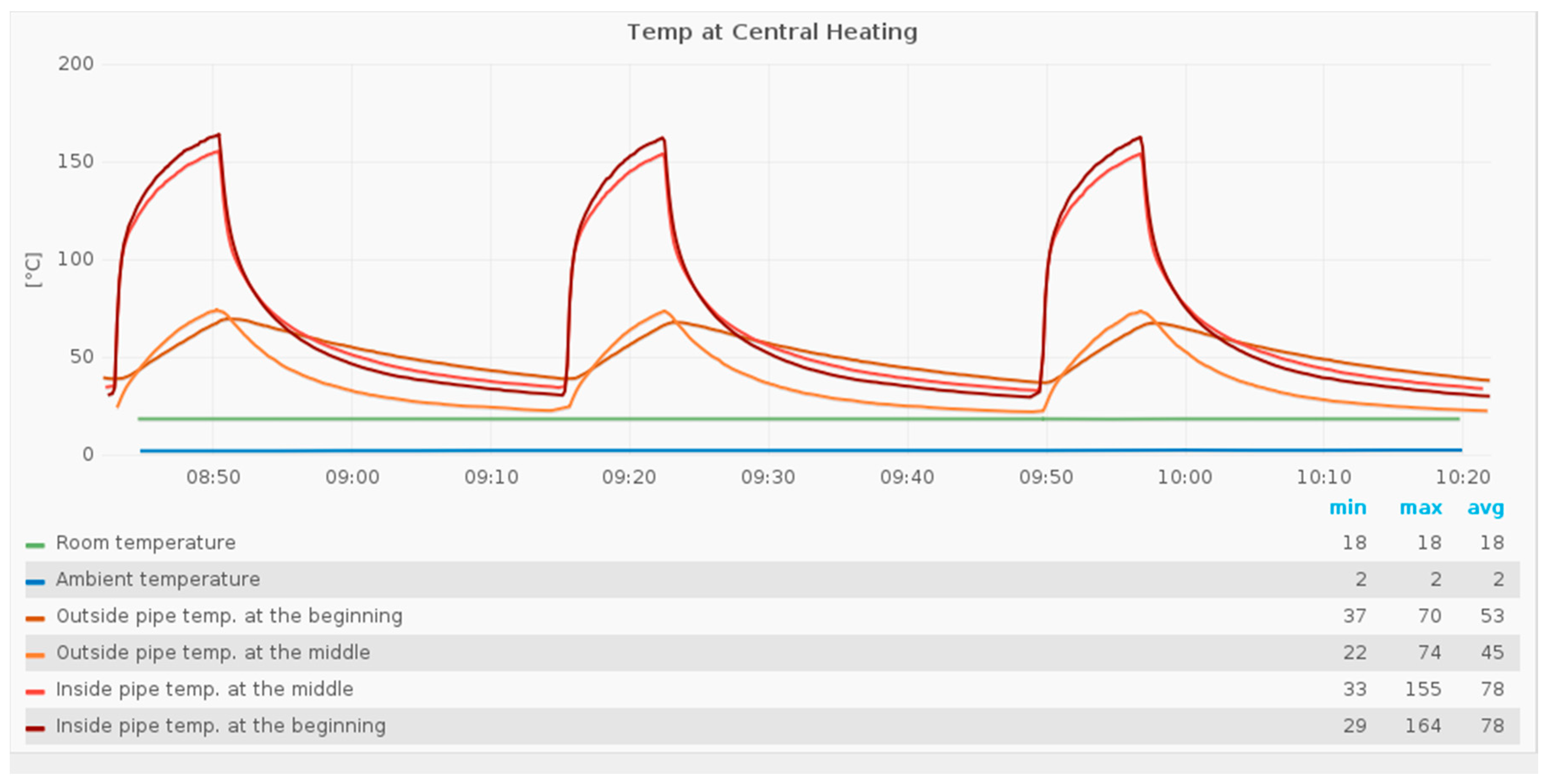
Moreover, data has to be collected from heating systems to calculate previously, if such an EHS is promising or not. That is why a measurement system was installed in one building at our university, where an oil-fired heating system is available. To avoid disturbing the real heating system, only temperature sensors are attached and the following temperatures are measured: room and ambient temperature, outside pipe temperature at the beginning and in the middle of the exhaust gas pipe as well as inside pipe temperature (equal to medium temperature) at the beginning and in the middle. The data are stored in a database and can be visualized via a web interface. An exemplary typical curve progression is shown for the 15th of November 2016 between 08:42 and 10:22 o’clock in Figure 1.
Visible are the aforementioned temperatures and an approx. 20/80 on/off behavior of the heating. The outside temperatures of the pipe have their maximum at about 74 °C, whereas the inside pipe temperatures reach a temperature of 163 °C. For the time being, the temperature levels seem to be appropriate to install a TEG-based EHS.
A second measurement system was installed in a private house. This building represents a normal one-family house and besides different temperatures, the energy consumptions of the pumps as well as the temperatures of a cockle stove in the living room are measured. Figure 2 shows a typical behavior for the 23rd of January 2016 between 00:00 and 23:59 o’clock. The measured data are again stored in a database and can be visualized by the web interface.
In the upper diagram of Figure 2, the temperatures are depicted and in the lower diagram the power consumptions are depicted. The central gas-fired condensing boiler recovers the latent heat of vaporization, which is reflected in the low maximum exhaust gas temperatures of about 75 °C. Therefore, a TEG-based EHS is not suitable for new condensing boilers as the exhaust temperatures are too low. Nevertheless, the on/off behavior of the boiler is also recognizable for this heating system. The power consumptions of the pumps are, on average, 45 W for the domestic hot water pump (runs only a few times a day), 6 W for the space heating pump (runs all day) and 2 W for the hot water circulation pump (runs almost continuously between 5:30 and 23:30 o’clock). The consumption of the other components (like blower and the heating electronics) is about 23 W, which results from the overall consumption minus the pump consumptions. In addition to that, the gas consumption of the heating is also measured (diagram is not shown in Figure 2) and during the on phase of the boiler, there is an average gas consumption of about 30 kW (the gas volume consumed is measured and then multiplied by the calorific value for natural gas, 10 ). An investigation based on the German BImSchV regulation has yielded an efficiency of 93.4%, after which 6.6% of the energy used is lost as waste heat. If the measured gas consumption is taken as the basis, the exhaust gas has a residual energy of 1.98 kW.
2.2. Heating Mockup
To avoid disturbing a real heating system, a heating mockup was planned and finally built-up in our laboratory. As a heat source for the heating mockup, an industrial hot air blower is used, at which the temperature and the velocity of the air can be controlled. The dimensions of the exhaust gas pipe correspond to reality. The real heating system on the campus is shown in Figure 3a and the heating mockup is shown in Figure 3b.
Real heating data are measured for two different heating systems, as mentioned in the previous subchapter, and are stored in a database. With a self-written LabVIEW program (Version 2015 SP1 (32 bit), National Instruments, Austin, TX, USA), it is now possible to control the heating mockup. For the heat source, there are two main options: to control the airflow (temperature and velocity) manually or automatically. The automatic mode is again divided into three options: to control the heating mockup according to the live data of the oil-fired heating on the campus, to give a special time range for the stored data in the database, which will then be reproduced by the heating mockup, or to give a txt-file as temperature profile. With this mockup, it is now possible to test a thermoelectric EHS at the exhaust pipe without interrupting a real system.
3. Development of the Energy Harvesting System
To develop the EHS for the exhaust pipe of the heating, a development process, which has already been presented in [23] is used. The modified scheme is shown in Figure 4 and the EHS is developed according to this guideline. The steps in the red frame can also be realized within a multiphysics simulation.
Regarding the development process, the selection of the heat source and the settings of the objectives have already been done in the previous section. The other steps can be summarized to five main steps, which are the ‘Thermal Design’, the ‘Selection of Thermoelectric Device’, the ‘Mechanical Design’, the ‘Electrical Design’ and ‘Control Concepts’.
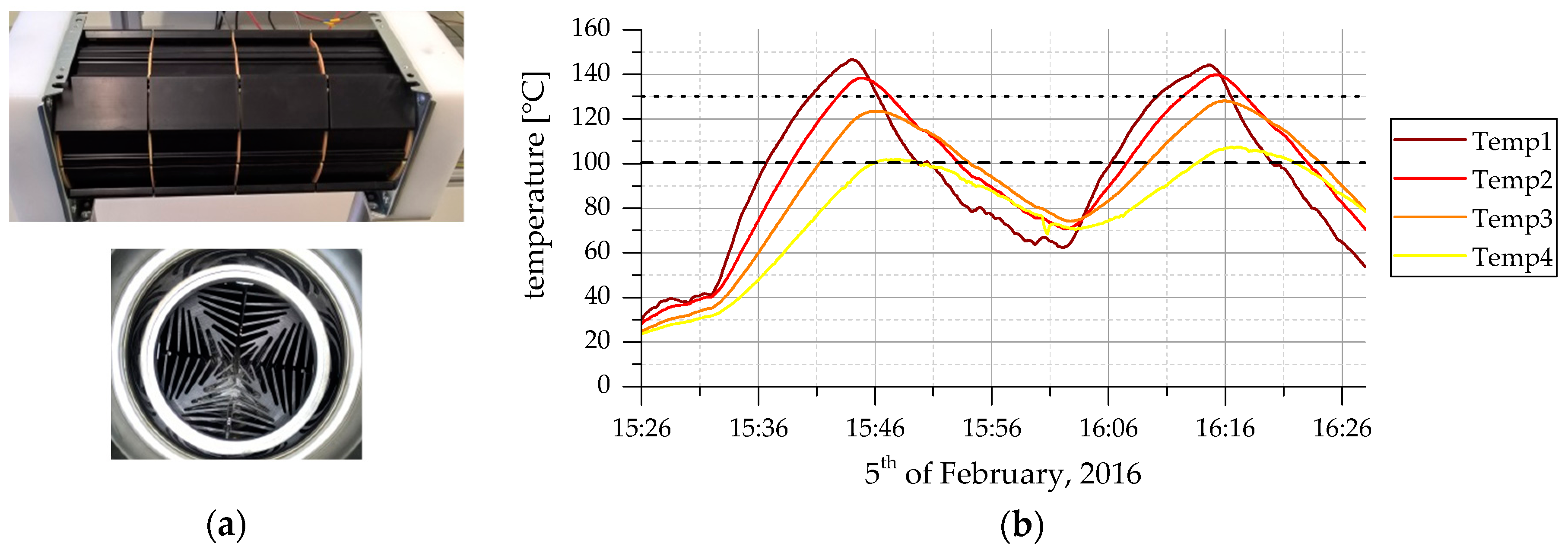
Concerning the thermal design, a segment cooling aggregate, [24], which is originally designed to cool down a flowing medium, is installed in the exhaust gas pipe. It is built up of cooling elements, which penetrate into the medium, collect the heat and transport it to the outer side of the pipe, see Figure 5a. There, the TEGs and the corresponding cooling units can be easily attached. This component is used to collect as much heat as possible from the exhaust pipe (the heat of the medium). This is, of course, an intervention in the real process and that is why a heating mockup was planned and finally built-up in our laboratory. Consequently, all following results are valid for a hot flowing medium in a pipe, but cannot be transferred directly to a real system, e.g., a real heating, before doing more studies on the influence for the real process. First measurements on the mockup with the installed clean segment cooling aggregate and a real heating behavior are shown in Figure 5b. The temperatures for each section of the segment cooling aggregate—in total there are four sections—are measured.
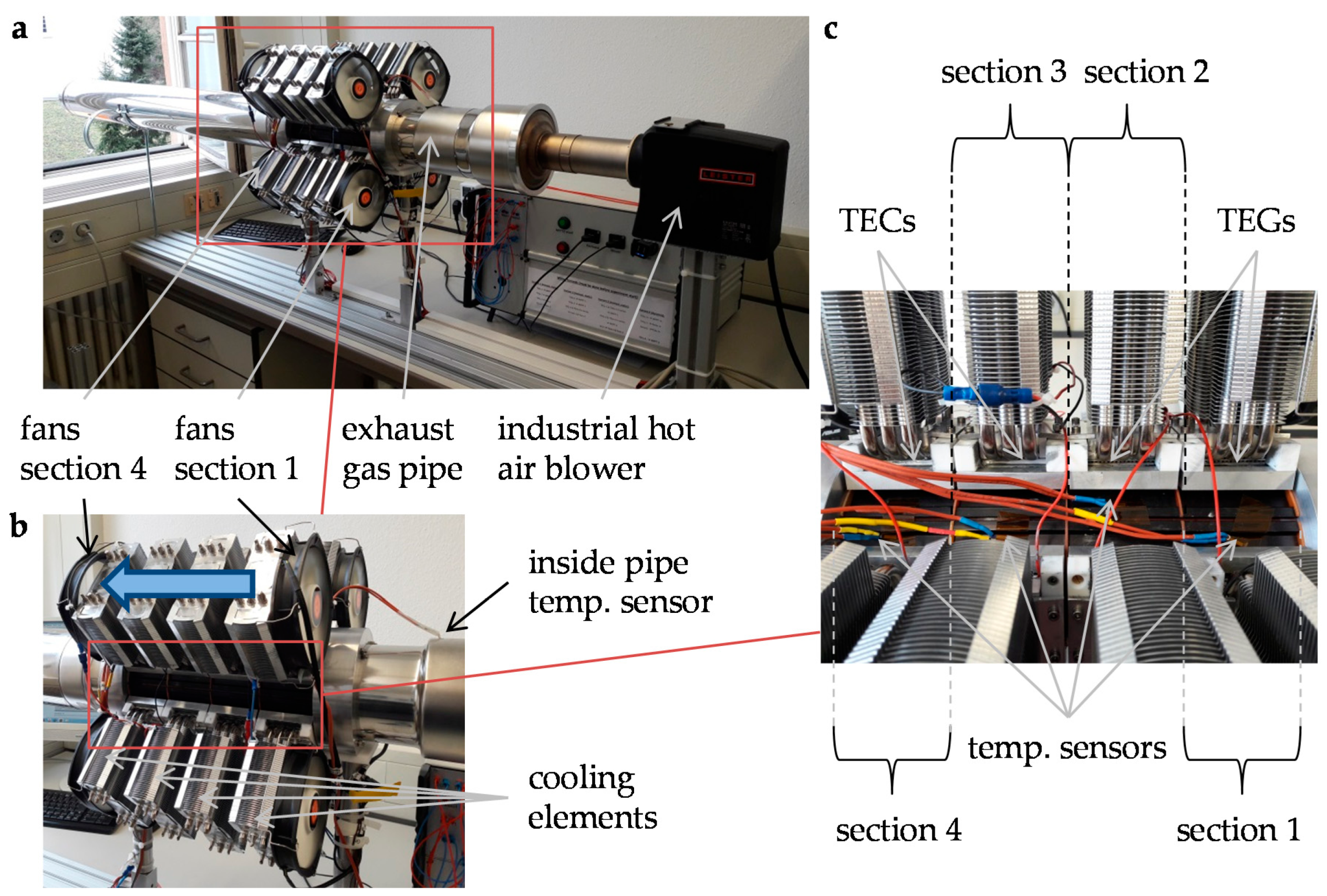
At each section, four thermoelectric devices can be attached, which are consequently under the same temperature conditions. In [25], it was shown that in some cases expensive TEGs can be replaced by cheap thermoelectric coolers (TEC, Peltier element). According to [25], for the first two sections, TEGs are used and TECs are used for the third and fourth sections.
The next step of the development process, the heat transfer of the waste heat, will be done with controlled air forced cooling elements. These are more suitable for real heating with an on/off scenario of 20/80 than liquid cooling elements, as described in [26]. Due to the lack of space, special small central processing unit (CPU) cooling elements are attached and the fans of the cooling elements are only mounted at the outside on the first and the fourth section. The fans on the first section blow air through the heat sinks and the fans on the last section pull the air from the heat sinks. So, there is airflow from the first section to the fourth. The mechanical setup of the heating mockup is shown in Figure 6. There, the four sections and the temperature sensors are visible for these sections; the inside pipe temperature sensor at the beginning, the cooling elements and the fans for sections 1 and 4 are also visible. The blue arrow in Figure 6b shows the air flow direction through the cooling elements.
Regarding the last hardware point of the development process, the electrical design, the prospective was to be very flexible. That is why a switch cabinet with a front panel was built up (see Figure 7a). As the thermoelectric devices of one section have the same temperature differences, they are connected in parallel. The individual blocks can then be individually interconnected (see front panel in Figure 7b). There are different connection possibilities, e.g., TEG blocks in series or in parallel or a mixture of both, connecting them to one or two MPPTs, connecting some TEG blocks with the fans or supplying the fans over a 12 V power supply. Beneath the front panel, the switch cabinet also includes an industrial PC to control the hardware setup via the LabVIEW program, an accumulator, the two MPPTs, the 12 V power supply, some relays (for system reconfiguration during operation mode; condition: all TEG blocks in series and between the relays), a vehicle plug to connect different loads as well as different measurement devices. All the measurement data are also written in the database and can be visualized by the previously mentioned web interface. The following measurements are carried out:
- Temperatures: at first/second/third/fourth section, inside pipe beginning, inside pipe end
- Voltages: Input MPPT1/MPPT2, Output MPPTs (equal to accumulator voltage), hot air blower
- Current: Input MPPT1/MPPT2, Output MPPTs, hot air blower
4. Simulation Model
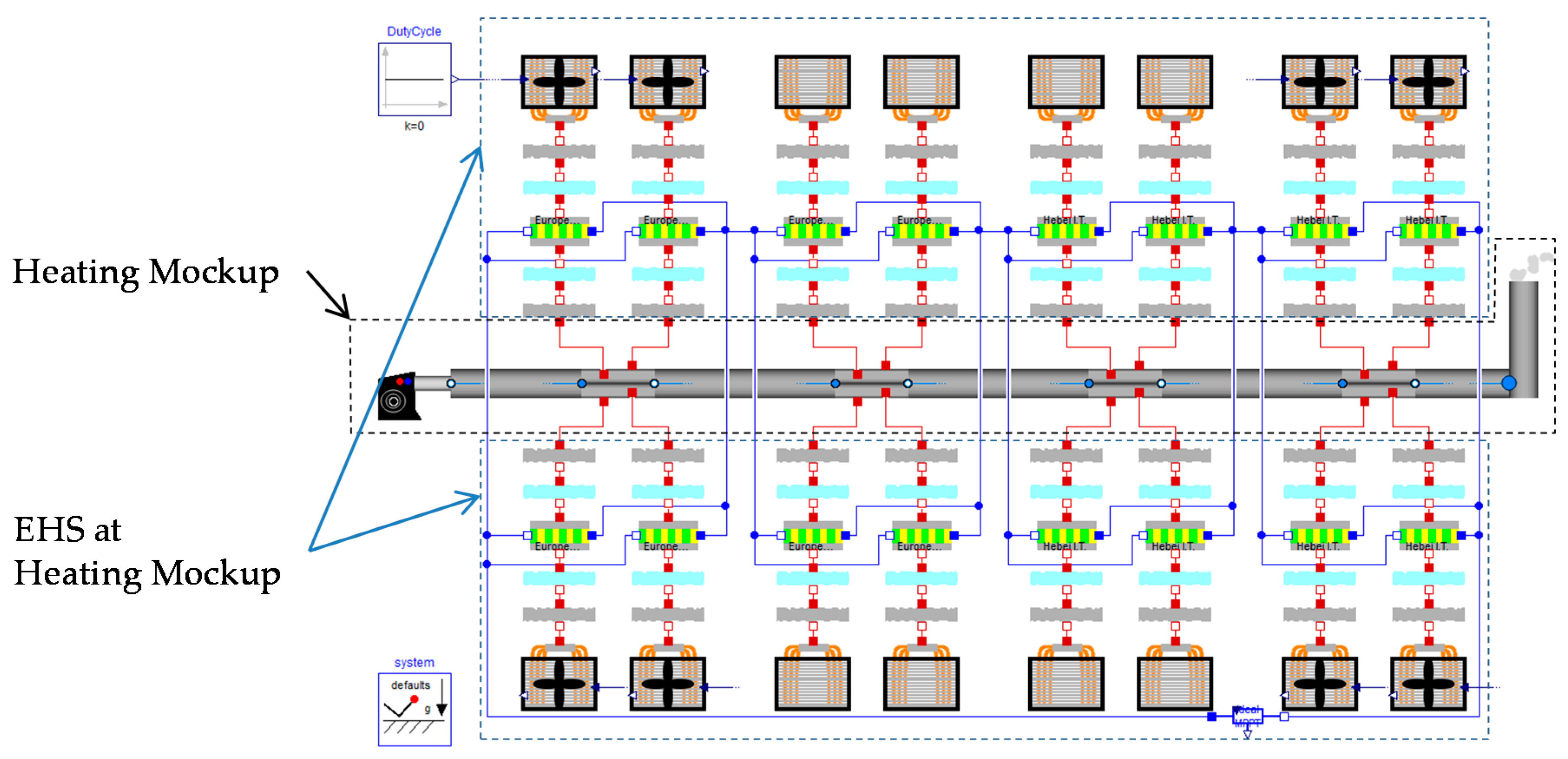
To simulate thermoelectric EHSs, a Modelica library called EHSTEG (Energy Harvesting Systems based on Thermoelectric Generators) was developed and applied; more information about the modeling of TEGs can be found in [27,28]. With this library, a complete system can be reproduced and this is also done for the heating mockup with the attached EHS (see Figure 8). The advantage with Modelica is that graphically, it looks very similar to the real system, which makes it easily usable and ensures that different physical principals can be simulated in one simulation environment (electrical, thermal, and so on). Visible in Figure 8 is the heating mockup consisting of the hot air blower, the exhaust gas pipe and the segment cooling aggregate components. The EHS is presented in the simulation model by heat transfer paste (grey components), air gaps (pale blue components), the TEGs/TECs represented by the yellow/green components as well as the cooling elements with and without fans. The blue connection lines present the electrical wiring between the thermoelectric devices, which can be adapted to the real wiring at the front panel. In the simulation model, the measured hot medium temperatures of the real heater, which are stored in the database, act as simulation input.
5. Results and Discussion
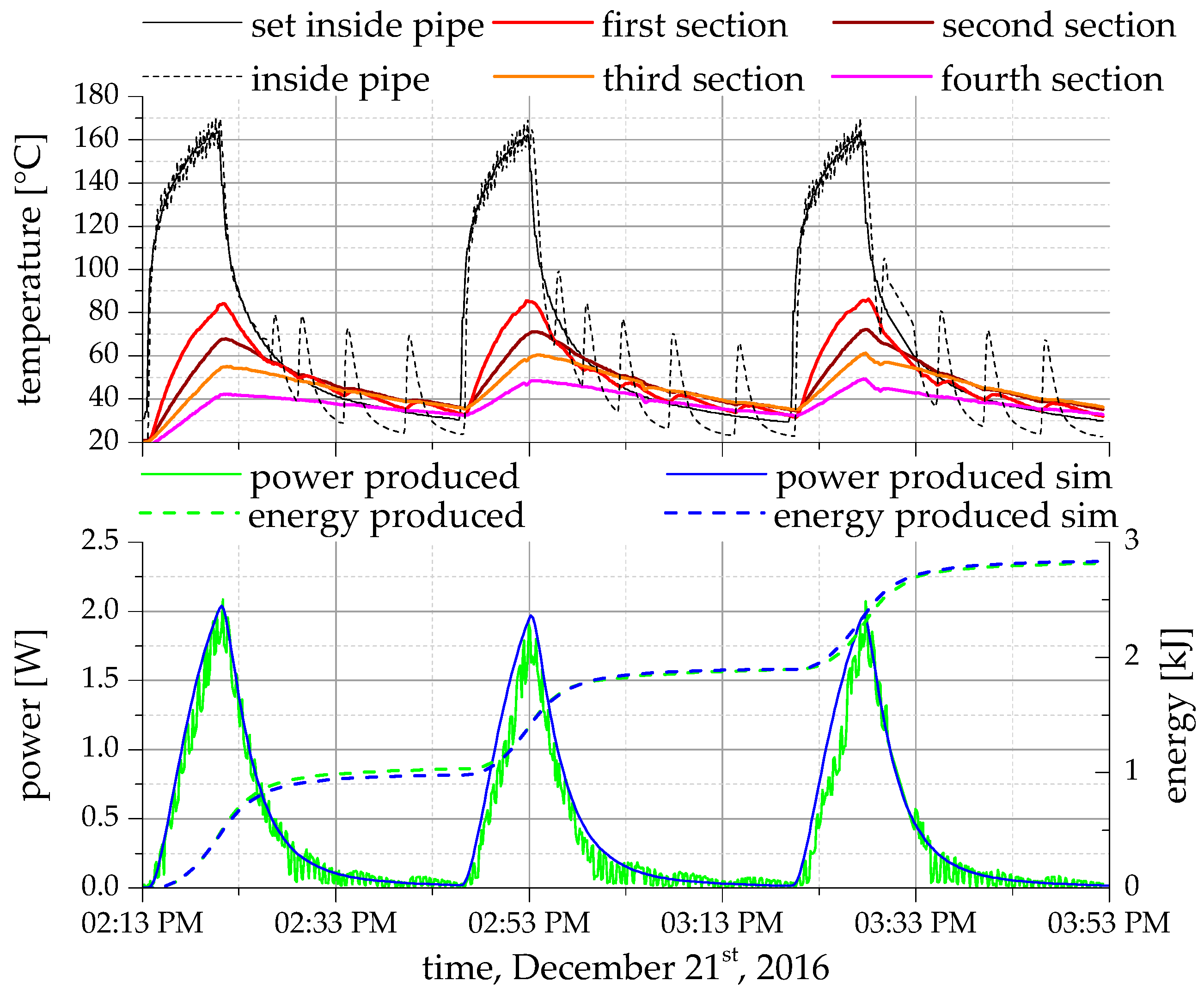
To test the prospective EHS for a real heating scenario, the real heating data for the oil-fired heating on the campus of the 15 November 2016 between 08:42 o’clock and 10:22 o’clock are given to the Heating Mockup, cf. Figure 1. Thereby, the following was selected as the connection variant, because it gives the best result: TEG block 1 and 2 are connected in series and then to MPPT1, whereas TEC block 3 and 4 are also connected in series and supply the fans of Section 1. Thus, in this scenario, a fan control over the duty cycle is not necessary, as the fan velocity will be self-controlled by the energy supported from TEC block 3 and 4. Consequently, the power delivered from TEG block 1 and 2 can be completely considered gained power of the system. The measurements as well as the simulation results are shown in Figure 9, where the upper diagram shows the measured temperatures as well as the set temperature inside the pipe and the lower diagram shows the measured gained power and energy as well as the simulated ones. As there are no additional consumers connected and the fans are directly supplied by TEC block 3 and 4, there is no direct power consumption. In the upper diagram of Figure 9, it is visible that the reproduced inside pipe temperature of the medium fits very well with the set temperature of the medium (which is also the real measured temperature) for temperatures over 80 °C. However, for lower temperatures there are some overshoots, which are related to the setting options of the hot air blower—it can only be adjusted for temperatures over 80 °C and due to that fact, it turns on briefly and then off again to control lower temperatures. Moreover, it is obvious that the temperatures of the single sections (now, with the attached EHS) are all under 90 °C, and for the last section the temperatures are approximately 50 °C. Consequently, the produced power is very low; this is visible in the lower diagram of Figure 9. The maximum gained power is around 2 W, which also matches with the simulation result. Since the oil-fired heating starts about 39 times a day, the daily energy output is approx. 36.4 kJ, which is about 10 Wh a day. Concerning that the number of heating days for this region is on average about 263 days according to [29]; this will be 2.63 kWh per year.
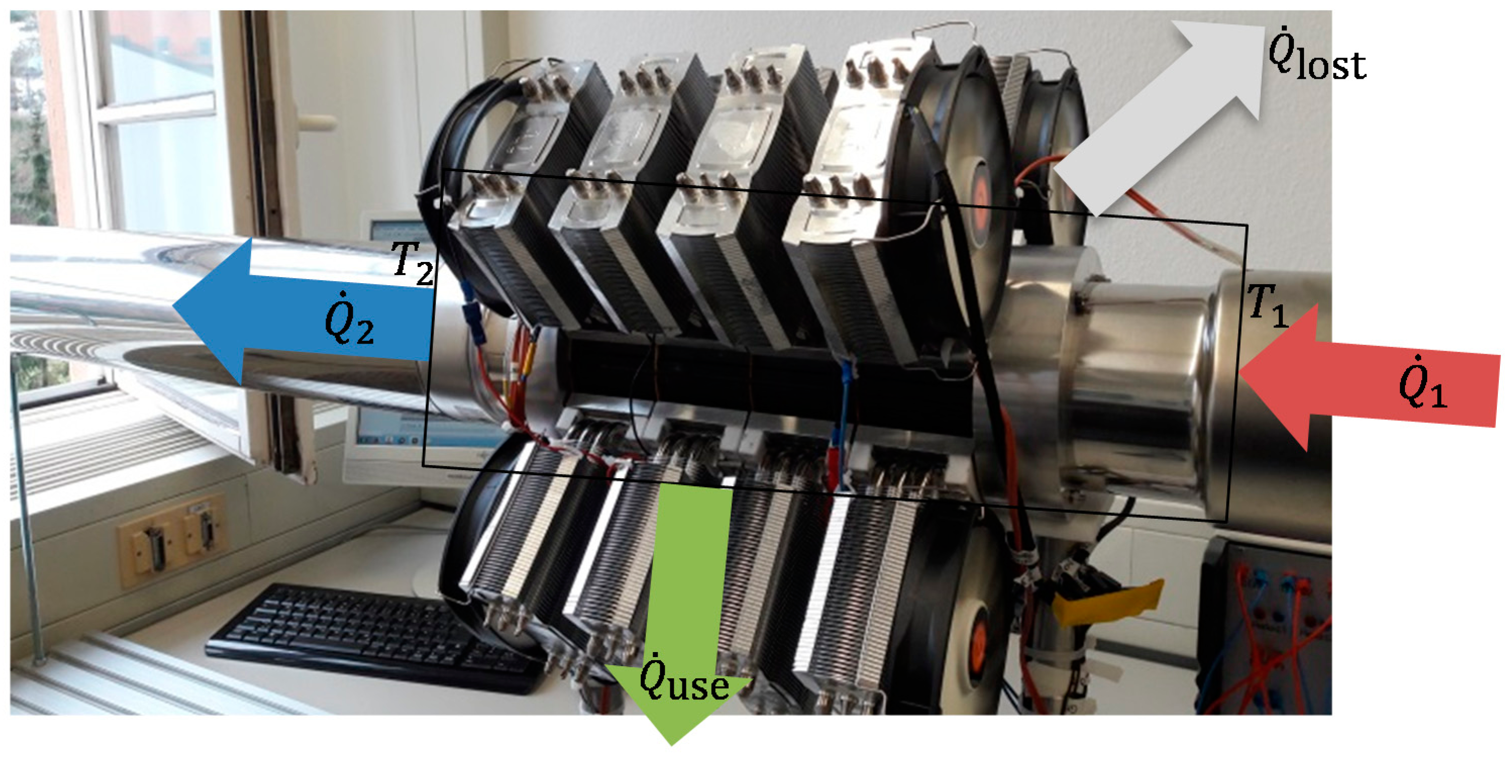
To calculate the efficiency of the EHS, Figure 10 represents the system consideration relating to the heat flow rates. The energy balance is given by
where is the inflow heat rate, the outflow heat rate, the useful heat rate and the lost heat rate. With the assumption of no heat losses, the useful heat rate can be calculated by
The temperatures and as well as the mass flow rate are measured or calculated values, whereas the specific heat capacity of the medium can be taken from the simulation. Thus, the useful heat rate here is approx. 560 W at the peaks, cf. Figure 9. The produced power is 2 W and so the efficiency is about 0.36%, according to the following equation:
where is the efficiency of the TEG-based EHS and the produced electrical power.
To conclude, it can be said that the presented EHS can harvest electrical energy from the exhaust gas of a heating system and thus it delivers a contribution for a more efficient usage of the inserted primary energy carrier. The efficiency of the entire system is currently not very high; however, since the waste heat is normally unused, such systems can be worthwhile. The energy amount is high enough to supply small DC applications, e.g., to charge a mobile phone. Also, it is possible to supply the heating and their components during a short blackout, but for this purpose, an accumulator is needed to store the electrical energy over the year—which, it has to be admitted, could also be loaded by the electrical grid.
To improve the EHS and to increase the efficiency of the heating, the water to be heated could be used as a cooling medium and thus, the water will be preheated (less energy input of the heating is necessary) and the thermoelectric devices will produce more electrical power.
It can be summarized that especially if there is a need for a robust, maintenance free and reliable power supply and the investment costs do not matter, thermoelectric EHS are highly recommended, e.g., for usage in space applications. To increase the energy yield, the number of TEGs or the temperature difference applied over the thermoelectric devices has to be enhanced.
Author Contributions
Marco Nesarajah conceived, designed and performed the experiments, analyzed the data and wrote the paper. Georg Frey supported the work through its expertise, knowledge, feedback and input.
Conflicts of Interest
The authors declare no conflict of interest.
References
- Quaschning, V. Erneuerbare Energien und Klimaschutz, 2nd ed.; Hanser: Munich, Germany, 2010; pp. 61–64. [Google Scholar]
- Steingart, D. Power Sources for Wireless Sensor Networks. In Energy Harvesting Technologies, 1st ed.; Priya, S., Inman, D.J., Eds.; Springer: New York, NY, USA, 2009; pp. 267–281. [Google Scholar]
- Briand, D.; Yeatman, E.; Roundy, S. Introduction to Micro Energy Harvesting. In Micro Energy Harvesting, 1st ed.; Briand, D., Yeatman, E., Roundy, S., Eds.; Wiley-VCH: Weinheim, Germany, 2015; pp. 1–5. [Google Scholar]
- Glossary Definition for Energy Harvesting. Available online: https://www.maximintegrated.com/en/glossary/definitions.mvp/term/Energy%20Harvesting/gpk/1144 (accessed on 15 March 2017).
- Rosenberg, Y.; Gelbstein, Y.; Daniel, M.P. Phase separation and thermoelectric properties of the Pb0.25Sn0.25Ge0.5Te compound. J. Alloys Compd. 2012, 526, 31–38. [Google Scholar] [CrossRef]
- Gelbstein, Y.; Davidow, J. Highly efficient functional GexPb1−xTe based thermoelectric alloys. Phys. Chem. Chem. Phys. 2014, 16, 20120–20126. [Google Scholar] [CrossRef] [PubMed]
- Gelbstein, Y. Phase morphology effects on the thermoelectric properties of Pb0.25Sn0.25Ge0.5Te. Acta Mater. 2013, 61, 1499–1507. [Google Scholar] [CrossRef]
- Kirievsky, K.; Shlimovich, M.; Fuks, D.; Gelbstein, Y. An ab-initio study of the thermoelectric enhancement potential in nano-grained TiNiSn. Phys. Chem. Chem. Phys. 2014, 16, 20023–20029. [Google Scholar] [CrossRef] [PubMed]
- Gelbstein, Y.; Tunbridge, J.; Dixon, R.; Reece, M.J.; Ning, H.P.; Gilchrist, R.; Summers, R.; Agote, I.; Lagos, M.A.; Simpson, K.; et al. Physical, mechanical and structural properties of highly efficient nanostructured n- and p-silicides for practical thermoelectric applications. J. Electron. Mater. 2014, 43, 1703–1711. [Google Scholar] [CrossRef]
- Anatychuk, L.I.; Kuz, R.V. Materials for Vehicular Thermoelectric Generators. J. Electron. Mater. 2012, 41, 1778–1784. [Google Scholar] [CrossRef]
- Hsu, C.-T.; Huang, G.-Y.; Chu, H.-S.; Yu, B.; Yao, D.-J. Experiments and simulations on low-temperature waste heat harvesting system by thermoelectric power generators. Appl. Energy 2011, 88, 1291–1297. [Google Scholar] [CrossRef]
- Date, A.; Date, A.; Dixon, C.; Akbarzadeh, A. Theoretical and experimental study on heat pipe cooled thermoelectric generators with water heating using concentrated solar thermal energy. Sol. Energy 2014, 105, 656–668. [Google Scholar] [CrossRef]
- Elefsiniotis, A.; Kiziroglou, M.E.; Wright, S.W.; Toh, T.T.; Mitcheson, P.D.; Becker, T.; Yeatman, E.M.; Schmid, U. Performance evaluation of a thermoelectric energy harvesting device using various phase change materials. J. Phys. Conf. Ser. 2013, 476, 1–5. [Google Scholar] [CrossRef]
- Kiziroglou, M.E.; Wright, S.W.; Toh, T.T.; Mitcheson, P.D.; Becker, Th.; Yeatman, E.M. Design and fabrication of heat storage thermoelectric harvesting devices. IEEE Trans. Ind. Electron. 2014, 61, 302–309. [Google Scholar] [CrossRef]
- Zhu, J.; Gao, J.; Chen, M.; Zhang, J.; Du, Q.; Rosendahl, L.A.; Suzuki, R.O. Experimental study of a thermoelectric generation system. J. Electron. Mater. 2011, 40, 744–752. [Google Scholar] [CrossRef]
- Bennett, G.L. Space Applications. In CRC Handbook of Thermoelectrics, 1st ed.; Rowe, D.M., Ed.; CRC Press: Boca Raton, FL, USA, 1995; pp. 515–537. [Google Scholar]
- Immer Mehr Erneuerbare Wärme. Available online: https://www.bmwi-energiewende.de/EWD/Redaktion/Newsletter/2016/07/Meldung/infografik.html (accessed on 15 March 2017).
- Zwei Drittel Aller Heizungen Veraltet. Available online: https://www.effizienzhaus-online.de/zwei-drittel-aller-heizungen-veraltet (accessed on 15 March 2017).
- Qiu, K.; Hayden, A.C.S. Development of a thermoelectric self-powered residential heating system. J. Power Sources 2008, 180, 884–889. [Google Scholar] [CrossRef]
- Quadflied, D. FNN-Störungsstatistik 2015; Forum Netztechnik/Netzbetrieb im VDE (FNN): Berlin, Germany, 2016. [Google Scholar]
- Qui, K.; Hayden, A.C.S. A natural-gas-fired thermoelectric power generation system. J. Electron. Mater. 2009, 38, 1315–1319. [Google Scholar] [CrossRef]
- Qui, K.; Hayden, A.C.S. Development of thermoelectric self-powered heating equipment. J. Electron. Mater. 2011, 40, 606–610. [Google Scholar] [CrossRef]
- Nesarajah, M.; Frey, G. Multiphysics simulation in the development of thermoelectric energy harvesting systems. J. Electron. Mater. 2016, 45, 1408–1411. [Google Scholar] [CrossRef]
- Segment Cooling Aggregates. Fischer Elektronik. Available online: http://www.fischerelektronik.de/web_fischer/en_GB/heatsinks/D03/Segment%20cooling%20aggregates/PG/LA1/search.xhtml (accessed on 16 March 2017).
- Nesarajah, M.; Frey, G. Thermoelectric power generation: Peltier element versus thermoelectric generator (TEC vs. TEG). In Proceedings of the 42nd Annual Conference of IEEE Industrial Electronics Society, (IECON2016), Florence, Italy, 23–26 October 2016; pp. 4252–4257. [Google Scholar]
- Nesarajah, M.; Felgner, F.; Frey, G. Model-based system assessment of thermoelectric energy harvesting from the exhaust gas pipe of oil-fired heatings. MM Sci. J. 2015, 570–575. [Google Scholar] [CrossRef]
- Felgner, F.; Exel, L.; Nesarajah, M.; Frey, G. Component-Oriented Modeling of Thermoelectric Devices for Energy System Design. IEEE Trans. Ind. Electron. 2014, 61, 1301–1310. [Google Scholar] [CrossRef]
- Nesarajah, M.; Exel, L.; Frey, G. Modelica Library for Dynamic Simulation of Thermoelectric Generators. In Proceedings of the 11th European Conference on Thermoelectrics, Noordwijk, The Netherlands, 18–20 November 2013; Amaldi, A., Tang, F., Eds.; Springer International Publishing: Cham, Switzerland, 2014; pp. 213–217. [Google Scholar] [CrossRef]
- German Weather Service. IWU: Gradtagszahlen_Deutschland.xls (Engl.: Degree Day Count Germany); German Weather Service (Deutscher Wetterdienst, DWD): Darmstadt, Germany, 2017.
Figure 1.
Measured temperatures at an oil-fired heating on the campus, visualized by the web interface.
Figure 1.
Measured temperatures at an oil-fired heating on the campus, visualized by the web interface.

Figure 2.
Measurement in a private house: (a) Measured temperatures at the heating and the cockle stove; (b) Power consumptions of the pumps in the heating.
Figure 2.
Measurement in a private house: (a) Measured temperatures at the heating and the cockle stove; (b) Power consumptions of the pumps in the heating.
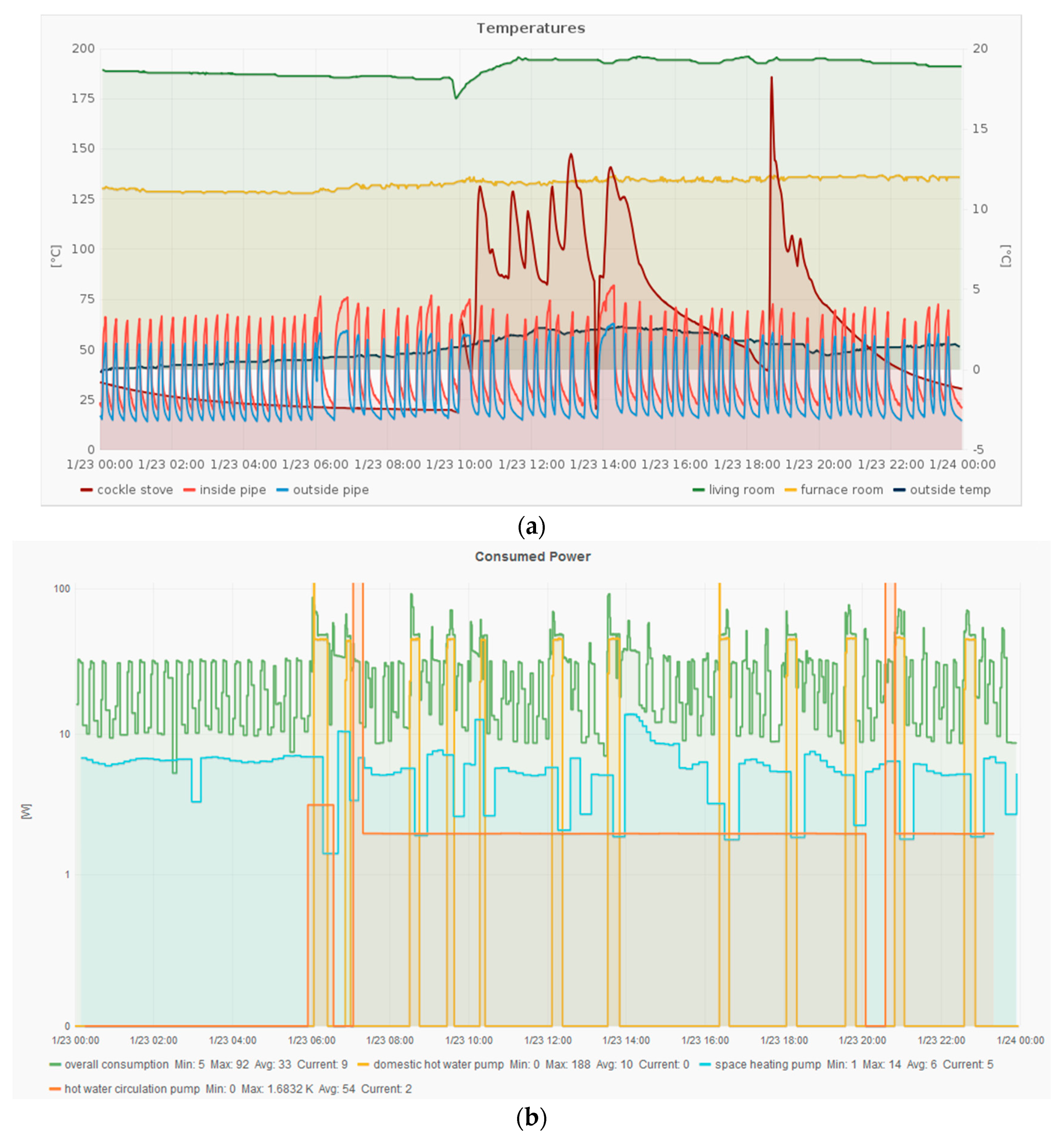
Figure 3.
Real system versus mockup: (a) Real oil-fired heating on the campus; (b) Heating mockup in the laboratory.
Figure 3.
Real system versus mockup: (a) Real oil-fired heating on the campus; (b) Heating mockup in the laboratory.
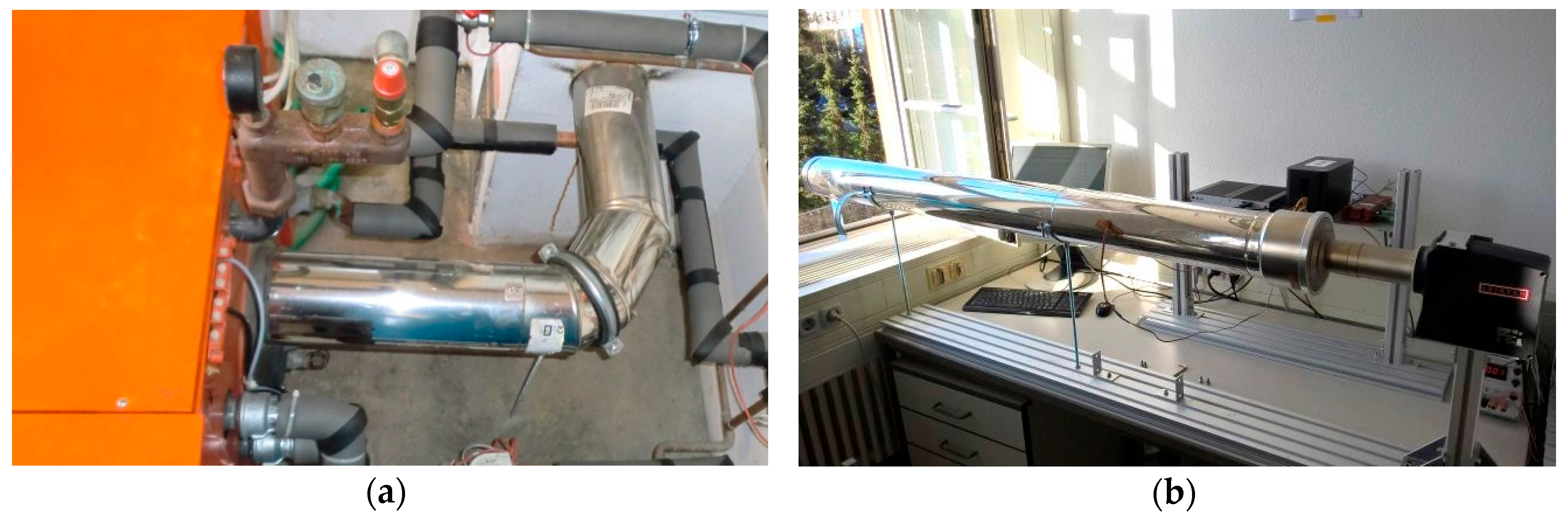
Figure 4.
Model-based development process for thermoelectric energy harvesting systems [23].
Figure 4.
Model-based development process for thermoelectric energy harvesting systems [23].
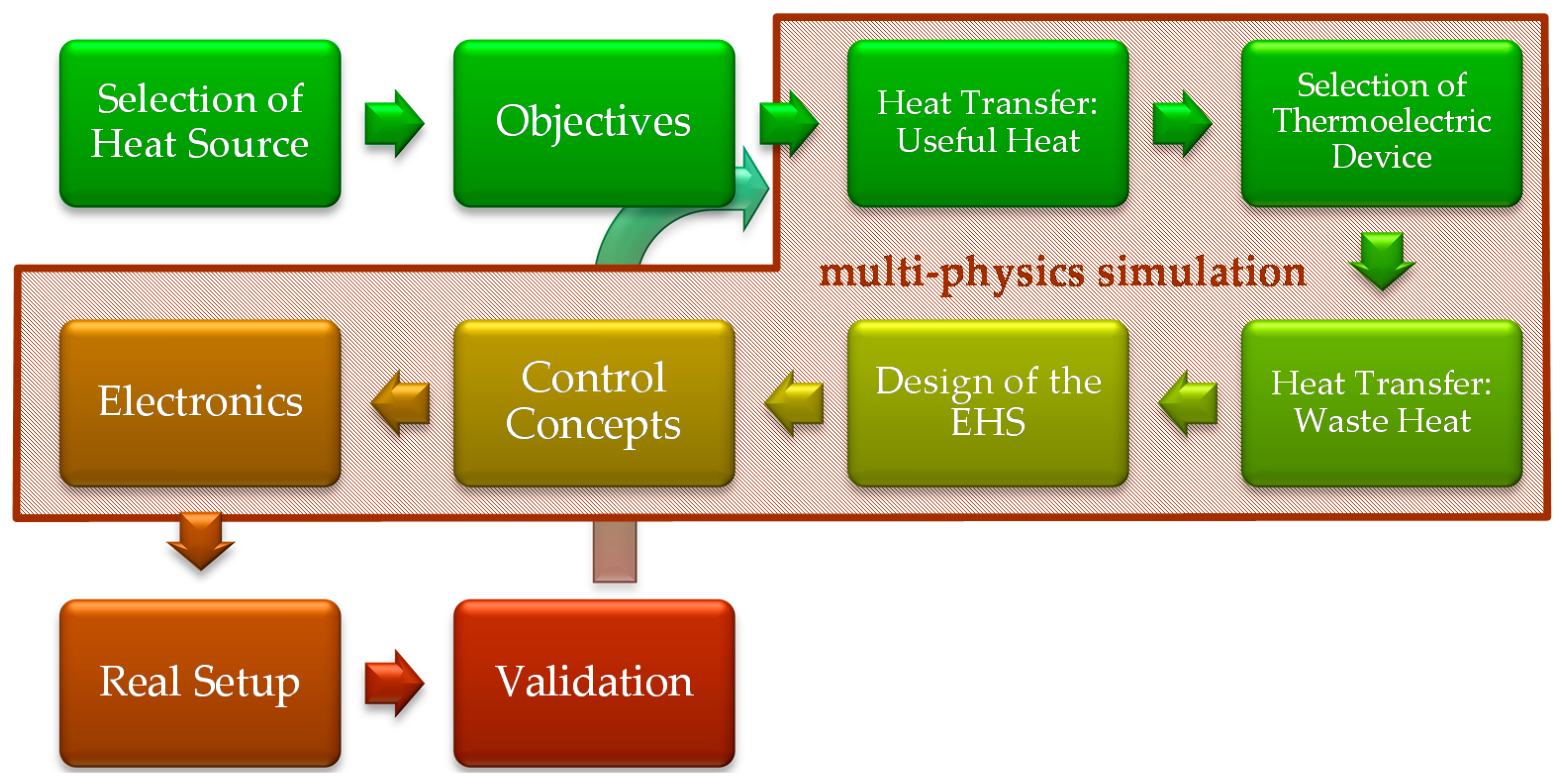
Figure 5.
Thermal design to collect the heat: (a) segment cooling aggregate to extract heat from flowing medium; (b) Temperature measurement of each section of the segment cooling aggregate for a 20/80 heating load.
Figure 5.
Thermal design to collect the heat: (a) segment cooling aggregate to extract heat from flowing medium; (b) Temperature measurement of each section of the segment cooling aggregate for a 20/80 heating load.

Figure 6.
Heating mockup with attached thermoelectric energy harvesting systems (EHS); (a) shows the complete setup; (b) shows an enlargement of a partial excerpt of (a); (c) shows an enlargement of a partial excerpt of (b).
Figure 6.
Heating mockup with attached thermoelectric energy harvesting systems (EHS); (a) shows the complete setup; (b) shows an enlargement of a partial excerpt of (a); (c) shows an enlargement of a partial excerpt of (b).

Figure 7.
Switch cabinet of the Heating Mockup: (a) complete switch cabinet; (b) Enlargement of the front panel to realize different wiring structures.
Figure 7.
Switch cabinet of the Heating Mockup: (a) complete switch cabinet; (b) Enlargement of the front panel to realize different wiring structures.
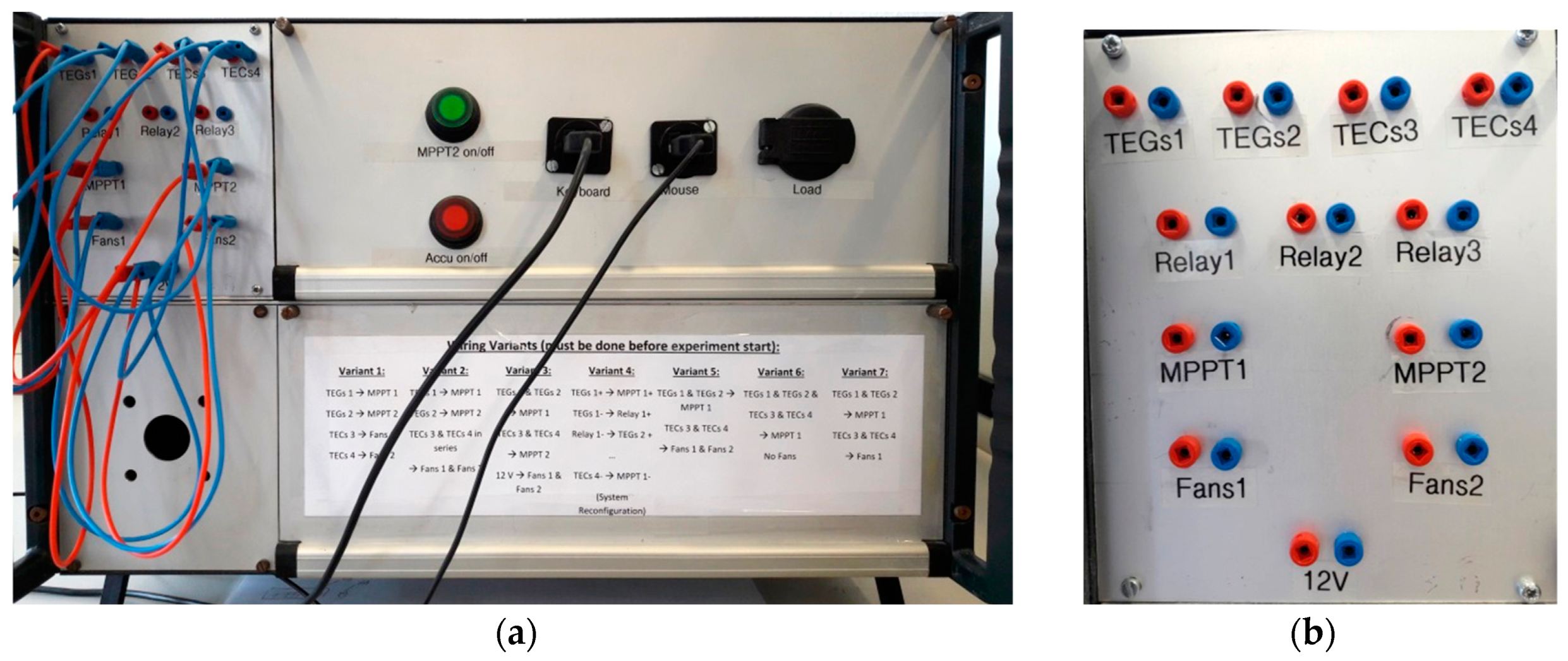
Figure 8.
Simulation model of the thermoelectric EHS at the heating mockup.

Figure 9.
Measurement and simulation data for the heating mockup: heating scenario of the oil-fired heating on campus on 15 November 2016 between 8:42 a.m. and 10:22 a.m., executed on 21 December 2016 at the Heating Mockup. Above: temperature curves of each section as well as the set and real inside pipe temperature at the beginning; below: produced power and energy of the EHS and the corresponding simulation results.

Figure 10.
Schematic system consideration of the heat flow rates for the EHS at the heating mockup.
© 2017 by the authors. Licensee MDPI, Basel, Switzerland. This article is an open access article distributed under the terms and conditions of the Creative Commons Attribution (CC BY) license (http://creativecommons.org/licenses/by/4.0/).
Share and Cite
MDPI and ACS Style
Nesarajah, M.; Frey, G. Optimized Design of Thermoelectric Energy Harvesting Systems for Waste Heat Recovery from Exhaust Pipes. Appl. Sci. 2017, 7, 634. https://doi.org/10.3390/app7060634
AMA Style
Nesarajah M, Frey G. Optimized Design of Thermoelectric Energy Harvesting Systems for Waste Heat Recovery from Exhaust Pipes. Applied Sciences. 2017; 7(6):634. https://doi.org/10.3390/app7060634
Chicago/Turabian StyleNesarajah, Marco, and Georg Frey. 2017. "Optimized Design of Thermoelectric Energy Harvesting Systems for Waste Heat Recovery from Exhaust Pipes" Applied Sciences 7, no. 6: 634. https://doi.org/10.3390/app7060634
Note that from the first issue of 2016, this journal uses article numbers instead of page numbers. See further details here.