The Performance and Fouling Control of Submerged Hollow Fiber (HF) Systems: A Review
by
 ,
,
Ebrahim Akhondi
1,2, 
Farhad Zamani
1,3,
Keng Han Tng
4,5,
Gregory Leslie
4,5,
William B. Krantz
1,6,
Anthony G. Fane
1 and
Jia Wei Chew
1,3,* 1
Singapore Membrane Technology Center, Nanyang Environment and Water Research Institute, Nanyang Technological University, Singapore 639798, Singapore
2
Young Researchers and Elite Club, Central Tehran Branch, Islamic Azad University, Tehran 1469669191, Iran
3
School of Chemical and Biomedical Engineering, Nanyang Technological University, Singapore 637459, Singapore
4
UNESCO Centre for Membrane Science and Technology, Sydney, NSW 2052, Australia
5
School of Chemical Engineering, The University of New South Wales, Sydney, NSW 2052, Australia
6
Department of Chemical & Biological Engineering, University of Colorado, Boulder, CO 80309-0424, USA
*
Author to whom correspondence should be addressed.
Appl. Sci. 2017, 7(8), 765; https://doi.org/10.3390/app7080765
Submission received: 27 June 2017
/
Revised: 22 July 2017
/
Accepted: 24 July 2017
/
Published: 28 July 2017
(This article belongs to the Special Issue Wastewater Treatment and Reuse Technologies)
Abstract
:The submerged membrane filtration concept is well-established for low-pressure microfiltration (MF) and ultrafiltration (UF) applications in the water industry, and has become a mainstream technology for surface-water treatment, pretreatment prior to reverse osmosis (RO), and membrane bioreactors (MBRs). Compared to submerged flat sheet (FS) membranes, submerged hollow fiber (HF) membranes are more common due to their advantages of higher packing density, the ability to induce movement by mechanisms such as bubbling, and the feasibility of backwashing. In view of the importance of submerged HF processes, this review aims to provide a comprehensive landscape of the current state-of-the-art systems, to serve as a guide for further improvements in submerged HF membranes and their applications. The topics covered include recent developments in submerged hollow fiber membrane systems, the challenges and developments in fouling-control methods, and treatment protocols for membrane permeability recovery. The highlighted research opportunities include optimizing the various means to manipulate the hydrodynamics for fouling mitigation, developing online monitoring devices, and extending the submerged HF concept beyond filtration.
1. Introduction
Low-pressure membrane processes, such as microfiltration (MF) and ultrafiltration (UF), are popular technologies in the water industry due to their proven efficiency in removing particles, colloids, and high molecular weight organics [1,2]. MF and UF membranes either are contained in a closed pressurized module or incorporated in an uncontained module that is submerged (immersed) in a tank. In submerged systems, the feed enters the tank at atmospheric pressure and the permeate is removed by applying suction on the permeate side of the membrane, which limits the transmembrane pressure (TMP) to <1 atmosphere and more typically to <0.5 atmosphere. The submerged concept is now well-established in the water industry, with applications in surface-water treatment, pretreatment prior to reverse osmosis (RO) in desalination and water reclamation, and membrane bioreactors (MBRs) [3]. Submerged membranes are either in a flat sheet (FS) format (vertically aligned) or hollow fiber (HF) form either horizontally aligned or more typically vertically aligned, often with suction applied at both ends. Submerged FS membranes are used only in MBRs, whereas submerged HFs cover a range of applications and consequently are much more common. The submerged HF concept has the advantages of a higher packing density, the ability to induce movement by mechanisms such as bubbling, and the feasibility of backwashing [4,5,6,7,8]. The focus of this review is the submerged HF concept.
Submerged membrane systems have to deal with fouling, which represents a major drawback that restricts the application of membrane processes in the water industry [8]. In general, fouling is a widespread and costly problem that affects membrane performance and is a complex function of the feed characteristics, membrane properties, and operating conditions [9,10,11]. Fouling mechanisms include physical and chemical adsorption, precipitation of sparingly soluble salts, the growth of biofilms, and the deposition of suspended matter onto or into the membrane [12]. Inadequate pretreatment, poor fluid management (process hydrodynamics), extreme operating conditions, and improper membrane selection are factors that exacerbate fouling [13,14].
The key parameters influencing fouling deposition in submerged HF membranes are the membrane characteristics (e.g., membrane material, the structure of membranes/fibers, fiber diameter, length, and tautness), feed properties (e.g., foulant characteristics, concentration, viscosity), operating conditions (e.g., temperature, flux), and hydrodynamic conditions (e.g., surface shear, air flowrate) [15,16]; these parameters are discussed in detail in this review. For feeds with a high solids concentration, such as membrane bioreactors (MBRs), cross-flow operation is required for the constant application of surface shear to mitigate concentration polarization and fouling deposition [14,17]. A common practice for submerged membranes in MBRs is two-phase bubbly flow [18,19,20]; other approaches could include mechanical vibrations [21,22,23] and particle fluidization [24], all of which are discussed in this review. An important development that coincided with the introduction of submerged HFs was the realization that dead-end filtration was attractive for dilute feeds (surface waters, RO pretreatment). In this case the filtration is operated in cycles, with the dead-end forward flux interrupted by backwashing and periodic surface flushing [25] or relaxation [26]. The submerged HF module makes backwashing feasible for polymeric membranes.
As HF membrane performance continues to improve, submerged HF systems are increasingly becoming more attractive for water treatment, particularly in membrane bioreactor (MBR) applications [27,28]. In spite of the importance of submerged HF processes and the extensive research literature on advancing such systems, a comprehensive review summarizing the current state-of-the-art systems with respect to performance and fouling control remains a gap in the literature. Therefore, this review focuses on recent developments in submerged hollow fiber (HF) membrane systems, the challenges and developments in fouling control methods, and treatment protocols for membrane permeability recovery.
2. Submerged Membrane-Filtration Applications and Benefits
Compared to conventional water-treatment techniques, the most popular of which involves an integrated system consisting of coagulation, flocculation, sedimentation, and disinfection, the production of drinking water via membrane technology is acknowledged to be attractive, especially in terms of higher quality water and ease of implementation [29,30,31,32,33,34]. The use of submerged hollow fiber membranes can be classified into three main application areas, namely, surface-water treatment for drinking purposes (Section 2.1), pretreatment for RO desalination and reclamation (Section 2.2), and membrane bioreactors (MBRs) (Section 2.3). The former two usually are operated in the dead-end filtration mode with intermittent backwashing, while the third is usually operated as a continuous filtration process with bubbling for inducing tangential shear to mitigate fouling. Table 1 summarizes the submerged membrane-filtration applications and benefits.
2.1. Surface-Water Treatment
The submerged membrane process is employed to remove microparticles and macromolecules, which generally includes inorganic particles, microorganisms, and dissolved organic matter (DOM) [34,43,44]. The microparticles and macromolecules present in the feed tend to affect the membrane pores adversely through pore blocking (i.e., sealing off the membrane pore entrance), pore constriction (i.e., narrowing the membrane pore channels), and/or cake-layer formation, all of which result in a decrease in the membrane permeability [35,45,46]. DOM ‘particles’, whose size approximates that of the membrane pores, can cause pore blocking, while microparticles and macromolecules larger than the size of the membrane pores result in a fouling layer on the membrane surface. Reversible fouling can be removed by hydraulic flushing/backwashing with air bubbles as scouring agents, whereas irreversible fouling binds more stubbornly to the membrane, thereby necessitating chemical cleaning [35,36,37,47].
2.2. Pretreatment for RO Desalination and Reclamation
Adequate pretreatment of the feed to reverse osmosis (RO) systems is essential to ensure optimal performance. Low-pressure membrane pretreatment is increasingly implemented prior to the RO unit operation in seawater reverse osmosis (SWRO) plants, and also RO plants for the treatment of surface water and treated municipal effluent [7,18,44,48,49,50,51]. Similar to surface-water treatment, the low solids content in these applications allows the low-pressure membranes to be operated in the dead-end filtration mode with intermittent backwashing. The main advantages of membrane filtration compared to conventional pretreatments such as coagulation, flocculation, and sand filtration are improved water quality, smaller footprint, less chemical requirements, and consistent quality of the filtrate [38,39,52,53]. Higher energy demand and membrane fouling are the main disadvantages of having a membrane-filtration system for RO pretreatment. RO membranes are very sensitive to foulants, so enhanced pretreatment via low-pressure membranes can significantly improve the performance and reduce the energy cost of RO plants [51]. In particular, RO systems with submerged membrane pretreatment have been proven to exhibit a consistently lower silt-density index (SDI) relative to conventional pretreatment [7,40,41,54,55]. Gravity-driven membrane filtration, which was initially developed as a low-energy process for surface water and diluted wastewater treatment, has also shown potential for seawater pretreatment that requires less energy and no chemical cleaning [56,57].
2.3. Membrane Bioreactors (MBRs)
Membrane bioreactor (MBR) technology, which combines conventional activated sludge treatment with low-pressure membrane filtration, is widely used for the treatment of wastewater [18,19,58]. The considerable growth of MBR is driven by the high quality of the water produced, increased water scarcity, and decreasing specific energy requirements [28,59]. The anaerobic membrane bioreactor (AnMBR), a combination of an anaerobic bioreactor and membrane filtration, also is a promising option for anaerobic treatment of wastewater [60,61,62,63].
A small footprint, complete solid-liquid separation, high volumetric organic removal rate, and higher effluent quality are some of the key advantages of the MBR and AnMBR [20,64,65,66]. In the submerged hollow fiber MBR, the membranes are directly immersed in the aeration tank. The results of bench-scale experiments, as well as many industrial and municipal operations, demonstrate high treatment efficiencies for chemical oxygen demand (COD), total suspended solids (TSS), and turbidity [19,42,63,67,68]. Although the MBR technology has been applied in many full-scale plants worldwide for treating municipal and industrial wastewater, membrane fouling and correspondingly increased energy consumption remain chief obstacles, as highlighted in a recent review [28]. Specifically, because membrane fouling diminishes productivity, fouling mitigation measures such as air scouring and frequent cleaning of the membrane are needed to restore the membrane permeability, which increases the energy requirement; furthermore, frequent cleaning shortens the membrane lifespan and results in higher membrane replacement costs. Aeration, bubbling, or gas sparging are the most common methods for mitigating membrane fouling; the important features of the interaction of bubbles with submerged hollow fibers (HF) are discussed in Section 5.2.
3. Fouling and Concentration Polarization in Submerged HF Systems
As noted earlier, submerged HFs can be operated in either a dead-end or cross-flow mode. In dead-end filtration, tangential shear is absent, while in cross-flow, there is shear on the membrane due to bubbling, vibration, or particle scouring. Figure 1 shows a schematic of dead-end and cross-flow filtration in a submerged system.
The operation of submerged HF membrane systems under either dead-end or cross-flow (usually induced by bubbles) conditions involves very different dynamics. Ideally the process is at steady-state with a fixed flux and TMP for cross-flow, while the process is cyclic with repeatable and regular changes in the TMP for dead-end filtration. However, irrespective of the mode of operation, some degree of fouling inevitably occurs, although membrane fouling is relatively less extensive in the cross-flow mode due to the continuous tangential shear on the membrane.
Accumulation of retained species on the membrane surface is unavoidable in membrane-based separation technologies for liquid feeds. In submerged HF membrane processes, depending on the membrane pore size, the retained species are particulates and macromolecules. The localized accumulation of particles or dissolved species on the membrane leads to concentration polarization (CP), which is the primary reason for flux decline or TMP rise during the initial period of a membrane-based separation in low-pressure processes [3,69,70]. CP is considered to be reversible and can be controlled in a membrane module by means of optimizing the process hydrodynamics. Unfortunately, membrane fouling resulting from CP can lead to an irreversible loss of membrane permeability [69,71]. Membrane fouling, the process by which foulants, namely colloidal (e.g., clays, flocs), biological (e.g., bacteria, fungi), organic (e.g., oils, polyelectrolytes, humic substances), and scaling (e.g., mineral precipitates in RO systems) foulants, deposit onto the membrane surface or in the membrane pores [72,73], may take different forms, the main mechanisms of which are adsorption (physical and/or chemical), pore blocking, deposition of a cake layer, and gel formation [74,75,76,77,78,79]. The extent of fouling, which stems from the nature of foulant-membrane interaction, is a complex function of the feed characteristics (e.g., foulant type, foulant concentration, and physicochemical properties of the foulants such as the functional groups, charge, size, and conformation [72,80,81,82]), operating conditions (e.g., inadequate pretreatment, inadequate control of the hydrodynamics of the system, excessive flux, and low cross-flow velocity (in cross-flow systems) [72,82,83,84]), and membrane properties (e.g., pore-size distribution, surface roughness, charge properties, and hydrophobicity [70,85,86,87]).
3.1. Fouling in Submerged Dead-End Filtration
In dead-end filtration, tangential shear is absent and particles are convected by the permeate flow to deposit on the membrane surface, thereby forming a growing cake layer with time. Physical cleaning approaches are typically implemented periodically for the effective removal of the fouling layer in order to prolong the filtration process and membrane lifespan in submerged membrane systems. Such approaches include relaxation (i.e., intermittent cessation of permeation), backwashing (i.e., reversal of permeate flow through the pores), and air backwashing with or without air scouring [25,88,89,90,91]. Filtration duration, backwash and relaxation durations, and backwashing flowrate are important parameters in the fouling mitigation of submerged HF membranes [26,90,92,93]. However, a major challenge in the application of these techniques is that the imposed permeate fluxes have to be elevated to maintain a given water production, which in turn could result in a higher fouling rate [94]. More details on backwashing and relaxation can be found in Section 7.
3.2. Fouling in Submerged Cross-Flow Filtration
For filtration with cross-flow, particle back-transport can be caused by the mechanisms of Brownian motion, shear-induced diffusion and/or inertial lift depending on the foulant size and the tangential shear rate [95]. For a submerged HF module, the major hydrodynamic technique to mitigate particle deposition on the fibers is bubbling, which induces unsteady-state shear at the membrane surface through turbulent eddies, fiber oscillations, particle scouring, and the recirculation of the bioreactor liquid [14,15,22,96,97]. The critical flux phenomenon (the flux below which negligible fouling occurs) also is observed in bubbled submerged HFs [98,99,100]. Bubbling intensity can increase the critical flux [100,101,102,103] and eventually reach a plateau beyond which it has little effect. Judd [104] gave typical values of the bubbling intensity (specific aeration demand) in submerged MBRs, defined either as the air flowrate per unit membrane area (m3/h m2) or airflow per unit permeate (m3/m3). For complex feeds, such as those encountered in an MBR, the imposed flux is usually ‘subcritical’ for the biofloc, but could be above critical for the supernatant colloids and macrosolutes. Under these conditions the submerged HF MBR typically initially shows a slow TMP rise that eventually becomes more rapid or displays a TMP ‘jump’ [105,106]. The TMP jump is not specific to submerged MBRs and can have a number of possible causes [106]. Importantly, earlier TMP jumps occur with higher fluxes and/or inadequate bubbling in the submerged HF MBR. More details on the role of bubbles and the attendant hydrodynamics are in Section 5.2.
4. Blocking and Blocking Mitigation in Submerged HF Modules
Blocking, clogging, or sludging in submerged HF modules obstructs local flows in the fiber bundle and results in an uneven flow distribution; this is detrimental to the performance and can promote membrane fouling [58,107]. It should be noted that this section is targeted at the obstruction in the module rather than membrane fouling. The root cause has been attributed to the accumulation of solids, and the growth and merger of cake layers formed on the individual fibers in the module. In such cases it has been shown that the overall performance of a module packed with HFs is worse than that of a single HF [108]. This aforementioned blocking is distinct from two other forms of blocking that can occur in submerged HF modules: (i) the term ‘blocking’ can also refer to that of the aerators especially in MBR systems [104]; (ii) it also can refer to the blocking or closure of the pores of the HFs. Both of the latter forms of blocking are distinct from the blocking that occurs due to solids accumulation within the spaces between the fibers in the membrane module that is the focus here.
The hydrodynamics within the module represents the key factor influencing the blocking phenomenon [107,109]. Stagnant regions caused by poor local flow lead to lower shear on the fibers, which in turn results in cake buildup and eventually local blocking [110]. The packing of the fibers within a module has been observed to be very different axially [111], which causes some non-uniformity in the flow. Due to the complexity of the hydrodynamics in the module [111,112,113,114,115,116], the buildup of cake deposits is not likely to be uniform either among the fibers or along the fiber surface. The misdistribution of fouling deposits, which is acknowledged to be a direct function of the non-uniformity of the flow within the HF module [109,115,117,118,119,120,121,122], can result in large variations in the performance of fibers at the same position in the module and in poorer performance of the fibers in the middle of the module [108].
The adherence of fibers to one another is traced to the buildup and eventual merging of cake layers, which in turn causes the fibers to foul more rapidly due to hindered local flow; hence, in time it results in blocking. It has been observed that some fibers tend to be held tightly together by the dense cake layers, while other fibers remain freely suspended [108]. The principal difference between constant-pressure and constant-flux operation is that the former is self-limiting whereas the latter is self-accelerating when fouling or blocking occurs [110]. The self-acceleration in the commonly used constant-flux operation is because (i) incipient blocking will reduce the local flow that thereby enhances the deposition [108], and (ii) the flux decline in some fibers has to be matched by a flux increase in other fibers to maintain a constant net flux that thereby accelerates blocking. Either local or global non-uniformities caused by the operating conditions or design parameters [104,109], including high packing densities, low cross-flow velocities, high feed concentrations, high TMP, or lack of means to promote unsteady-state shear [123] (e.g., bubbling [14]), contribute to a greater tendency for blocking.
The control of fouling and blocking in practice is primarily through employing some or all of five strategies [109]: (i) pretreatment of the feed, (ii) physical or chemical cleaning protocols, (iii) flux reduction, (iv) aeration enhancement, and (v) chemical or biochemical modification of the feed. For (i), it is widely acknowledged that upgrading the pretreatment, in particular the screening, is pivotal to the successful retrofitting of an ASP (activated sludge process) or SBR (sequencing batch reactor) with an MBR [109]. Hair, rags, and other debris tend to aggregate at the top of the submerged HF module and become entwined with the filaments, thereby preventing their effective removal by backwashing [124]. Therefore, adequate removal of the solids before the submerged HF module is key to mitigating blocking. Methanogenic [125] and chlorinated [126] pretreatments have also been explored, as well as hybrid processes, both of which add an additional unit operation before the membrane module [127,128,129,130]. With respect to (ii), physical cleaning tends to remove reversible fouling while chemical cleaning can remove some irreversible fouling. The primary physical cleaning parameters include duration, frequency, and backwash flux [88,107,109,131,132], while the type and concentration of reagents are the important parameters for effective chemical cleaning [124,131,133,134,135,136]. Regarding (iii), flux reduction is not as cost-effective as might be expected, but the attendant extension of membrane lifespan and smoother operation may counterbalance some of the increased cost. Flux reduction is commonly implemented as a sustainable permeability operation (i.e., at a lower flux to maintain stable operation) or as an intermittent operation (i.e., at a higher operating flux with intermittent remedial measures such as relaxation and/or backwashing). As for (iv), aeration is acknowledged to be the main mixing mechanism [137,138] that generates a large amount of momentum that in turn reduces dead-zones and short-circuiting [139]. More details on aeration are given in Section 6.2. In connection with (v), the nature of the biomass in MBRs can be partially controlled through the addition of coagulants or flocculants [124,140,141,142,143,144] and adsorbent agents (e.g., activated carbon [145,146,147,148,149,150,151]). In addition, the bioprocess parameters, such as the sludge retention time (SRT), influence the biomass and supernatant as well as the fouling [152].
A suitable mitigation means for blocking has to be determined for each MBR plant. For example, a Mitsubishi Rayon unit failed to resolve the blocking problem via measures such as overnight relaxation and intensive or regular chemical cleaning, but regular backwashing for 30 s during each permeate production cycle achieved a stable low permeation flux [104]. To limit blocking, the PURON® system is designed with free movement of the filaments at the top of the module. This allows for larger solids, such as hair and agglomerated cellulose fibers, to escape without causing clogging in this region. The fibers are reinforced by an inner braid, to withstand the lateral movement of the filaments that subjects them to mechanical stress [153].
A major difficulty in the mitigation of module blocking in submerged HFs is the lack of simple techniques for in situ monitoring of the phenomenon. One approach that has been developed [122] is based on the assumption that blocking within the module is initially localized, which would result in a localized drop in flux relative to the overall average flux. Using a simple array of flow detectors mounted in the permeate header, it is possible to measure local fluxes and identify fiber regions that become less productive. It was shown that shifts in the standard deviation of the local fluxes was much more sensitive to local blocking than shifts in the overall system TMP. In the aforementioned study, the flow detectors were based on constant temperature anemometry strips, but other low cost detectors could be used.
5. Parameters Affecting the Performance of a Submerged Hollow Fiber System
Several factors, including the feed characteristics, membrane and module properties (e.g., fiber length, diameter, and looseness), and hydrodynamic properties (e.g., flowrates), collectively affect the performance of submerged HF systems.
5.1. Membrane Properties and Module Configurations
5.1.1. Membrane Materials and Surface Morphology
Membrane characteristics such as material, surface charge, hydrophilicity, pore size, and pore morphology significantly impact membrane performance and the fouling potential. Membrane surfaces can be modified to combat and mitigate adhesive fouling [25]. The membrane material largely influences the initial rates of deposition of foulants due to the tendency of some materials to adsorb certain solutes or particulates more readily, as quantifiable by the Gibbs free energy of foulant-membrane interaction [154,155,156,157]. When the adsorption becomes such that the effective pore size of the membrane is reduced, the flux is adversely affected [158,159,160].
It is well-known that the severity of fouling increases as the hydrophobicity of the membrane increases, because organic molecules have a higher affinity for hydrophobic materials [47,159,161,162,163,164,165]. Most commercial MF and UF membranes are made from relatively hydrophobic polymers (e.g., polysulfone, polyethersulfone, polypropylene, polyethylene, and polyvinylidene-fluoride (PVDF)), due to their excellent chemical resistance, and thermal and mechanical properties [83,166,167,168,169,170]. In some cases, the membranes are modified by additives to confer increased hydrophilicity for water applications. The charge on the membrane surface also plays a role in either exacerbating or mitigating fouling. Attractive electrostatic forces between a charged surface and the co-ions in the feed solution increase fouling [161], while repulsive electrostatic forces mitigate fouling. In general, a low surface charge or electrically neutral surfaces tend to show better anti-fouling properties during the initial stages of membrane fouling [163,171]. Since most colloidal particles, such as those in natural organic matter (NOM), that tend to deposit are negatively charged, membrane surfaces are usually negatively charged [161,168,169], although positively charged membrane surfaces are also used to repel positively charged colloids and cations [172]. Compared to having just a positively or negatively charged membrane surface, the addition of a zwitterionic charged material, one composed of neutral molecules that have a positive and a negative electrical charge, has been shown to confer better anti-fouling properties [173]. Inorganic nanoparticles (such as SiO2 [174,175], Al2O3 [176,177], clay [178,179], ZrO2 [180,181,182], TiO2 [183,184], and ZnO [185,186]) also have been used to improve polymeric composite membranes, conferring improvements in the mechanical properties, thermal stability, hydrophilicity, permeation, and antifouling performance of membranes [165].
5.1.2. Fiber/Module Arrangement
Experimental efforts have consistently established that a lower HF packing density, either by having fewer fibers [108], widening the HF module [187,188], or by varying the module configuration [97,189], is linked to a lower fouling tendency. Other than the HF packing density, modules that are designed to enhance either lateral flow [190] or lateral movement of the fibers [188] are known to further improve the performance of submerged HF systems. In a carefully controlled arrangement with nine fibers in a matrix, a detailed analysis has shown that the performance of individual fibers varied with their position in the module, such that the fibers at the edge performed best, while those in the center surrounded by other fibers performed the worst [108]. The underlying reason for this was tied to the lower cross-flow velocity at the center of the module and the ‘flux competition’ for the surrounded fiber. Interestingly, whereas Yeo and Fane [108] found that a single fiber outperformed a multi-fiber HF module in a single-phase (no bubbling) system due to module blocking, Berube and Lei [191] found that a multi-fiber module performed better than a single fiber in the presence of bubbles (i.e., two-phase flow) due to inter-fiber interactions leading to mechanical erosion of the foulant layer.
Simulation results by Liu et al. [192] revealed that MBRs fitted with hollow fibers in a vertical orientation experienced 25% more membrane surface shear in the filtration zone than horizontally oriented fibers at the same aeration intensity. They also found that the addition of baffles in the membrane modules is a feasible way to promote turbulence and shear in the upper section of the membrane module.
5.1.3. Fiber Looseness
Fiber movement plays an important role in determining the extent of particle deposition on submerged HFs in bubbling cross-flow operation. Greater fiber movement, which can be achieved by using looser fibers, enhances the back-transport of the foulants from the membrane and also results in physical contact between the fibers, both of which reduce fouling [16]. Tight fibers studied by Wicaksana et al. [15] showed a 40% faster rate of TMP rise compared to fibers with a 4% looseness, where the looseness percent is based on the difference between the fiber length and the linear distance between the fixed ends of the fiber relative to the fiber length; this implies that approximately 40% of the fouling mitigation brought about by the bubbles was due to movement of the loose fibers. Simulations by Liu et al. [193] showed that fiber displacement and membrane surface shear are highly variable at different locations along the fiber and with time. In addition, increasing the fiber looseness from 0.5% to 1% increased the average surface shear by 50.4% (0.56–1.13 Pa) for fibers with the same diameter. Yeo et al. [194] found that increasing the looseness from 0% to 1% decreased the fouling tendency regardless of the bubble size, whereas increasing the looseness from 1% to 2% increased the fouling tendency. This suggests an optimum fiber looseness, whereby too much displacement may move the fiber away from the influence of bubbles. This effect will depend on the module geometry relative to the bubbling zone. It is also known that too much looseness can lead to fiber breakage.
5.1.4. Fiber Diameter
A smaller HF diameter has been experimentally shown to improve the performance of submerged HF systems [15,16,187] due to the attendant greater fiber mobility [15], which can be further enhanced by bubbling [16] or turbulence in general [187]. However, theoretical analysis shows that a smaller HF diameter leads to a higher pressure drop along the fiber lumen, such that a higher suction pressure is required for a given average imposed flux [187]. On the other hand, simulations show that the average surface shear was 67% higher for fibers with a diameter of 1.3 mm relative to fibers with a diameter of 1.0 mm that had an identical Young’s modulus and looseness [193]. The interplay of these two effects suggests an optimal fiber diameter that balances flux enhancement with flux-distribution and suction-pressure considerations [187].
5.1.5. Fiber Length
Simulation studies have indicated that longer fibers lead to a higher lumen-side axial pressure drop and consequently an uneven permeation flux distribution along the fibers, which can result in the particle deposition being more severe near the suction ends relative to the closed end of the fibers due to a higher local flux [99]. Experimental evidence is in agreement that this non-uniform pattern of particle deposition along the fibers is more apparent for longer fibers (lengths tested were in the range of 0.3–1 m) [100,195,196,197]. On the other hand, fouling control is facilitated by the greater mobility of longer fibers [98], which can be enhanced by bubbling [15].
5.2. Hydrodynamics in Submerged HF Membranes
Enhanced surface shear, for example caused by an increased cross-flow velocity, is a common strategy to control concentration polarization and fouling in submerged HF systems [138,198,199]. Unsteady-state shear, such as two-phase flow (i.e., gas bubbles or fluidized particles) and vibration, is more energy-efficient than steady-state shear [123]. Air bubbling is particularly attractive in MBRs for aeration, mixing, and augmenting liquid flows [14,82,200,201].
5.2.1. Role of Air Bubbles
The use of bubbly flow has been reviewed by Cui et al. [14] and more recently by Wibisono et al. [82]. The major benefit of rising bubbles is the unsteady or transient shear stress at the membrane surface that causes particle back-transport away from this surface [14,15,22]. Figure 2, based on Cui et al. [14], illustrates the possible interactions of bubbles with the surface of hollow fibers and shows three different effects on the submerged hollow fibers: (i) a shear stress on the surface of the hollow fiber induced by the wake generated by the rising bubbles, (ii) fluctuating liquid flows transverse to the fibers induced by the bubbles, and (iii) lateral fiber movement induced by the bubbles that depends on the looseness of the fiber. Wibisono et al. [82] indicated that aeration intensity not only enhances the hydrodynamics, but also can affect the biomass properties in aerobic membrane bioreactors. Yeo et al. [202] [Yeo, 2017 #321] showed that aeration also influenced the biofilm growth. In addition, Cabassud et al. [203] reported that bubbles seem to alter the structure of the cake or fouling layer such that the specific resistance is reduced. They based this conclusion on the observation that gas sparging applied to the MF of particles increased the fluxes significantly after a period of flux decline at the higher feed concentrations. Wang et al. [204] correlated the bubble hydrodynamics with the critical flux and found that bubble momentum and the bubble-membrane contact area had the most positive correlation with the local critical flux. However, Du et al. [201] found that the shear stress associated with the bubbles was insufficient to mitigate the deposition of fine (1.75 μm) particles.
5.2.2. Bubble Characteristics
Several techniques have been used to characterize the hydrodynamic conditions in submerged HF systems. Particle-image velocimetry (PIV) [205] has shown that the bubble size increases with height along the membrane module due to the reduced hydrostatic pressure as the air bubbles move upward, and varies over a wide range of 0.2–50 mm, with a predominant size range of 3–5 mm. A strong sheltering effect attributed to the hydrodynamics was observed within the hollow fiber module that resulted in a 10-fold reduction in the axial velocity relative to the velocity outside the fiber bundle [110]. Nguyen Cong Duc et al. [206] used a bi-optical probe to characterize the bubble velocity, distribution, and size throughout submerged full-scale HF modules. The shear stress was observed to be an important parameter in controlling particle back-transport from the membrane surfaces. Fulton et al. [207] studied the sparged bubble characteristics and the induced shear forces at the surface of submerged hollow fiber membranes using an electrochemical method. The shear stress was observed to be highly unpredictable over time and heterogeneously distributed within the module, ranging from 0.1 to over 10 Pa. Also, no correlation was observed between the shear stress and the bubble frequency or rise velocity. However, this does not corroborate with the general observation of better fouling control with increased aeration intensity (see Section 5.2.3) and also with the results of Yeo et al. [194], who observed an increase in the shear stress with increasing bubble frequency for all bubble types. These disparate observations highlight the challenge in achieving well-distributed two-phase flow in the submerged HF module. The importance of this was shown by Buetenholm et al. [208], who used X-ray computer tomography to detect the instantaneous displacement of fibers in an aerated HF bundle. The data were then incorporated into a computational fluid dynamics (CFD) simulation to allow optimization of the module design and aeration. More recently, Wang et al. [204] used a high speed video camera to characterize the bubble characteristics and direct observation through the membrane (DOTM) to determine the corresponding critical flux of micron-sized polystyrene particles. They found that the local bubble momentum and bubble size had the most positive correlation with the local critical flux.
5.2.3. Effect of Gas Flowrate
It has been reported in many studies that the filtration performance can be improved by controlling the bubbling rate [15,16,209,210]. On the one hand, the critical flux improves in an approximately linear fashion with respect to gas flow in submerged HF systems [100,101,102,103,204]. On the other hand, for different sizes of fibers, it has been shown that a modest gas flow can increase the final flux by a factor of 3–6 in a yeast suspension, but the enhancement quickly plateaus at higher gas flowrates such that further increases in the gas flowrate achieve negligible enhancement [187]. This disparate behavior stems from the slugging phenomenon, whereby large changes in the gas flow have a negligible effect on the velocity of the film that is formed adjacent to the surface of the fiber [211]. Similar plateaus have been observed in submerged HF systems for sewage treatment and drinking-water treatment [191,210]. It has been observed that at high gas flowrates (namely, 40 L/h), a maximum flux was observed, after which the flux started to decline [212]. This phenomenon was explained by the relationship between the bubble size and air flowrate; since bubble size tends to increase with the air flowrate, the bubbles become so large after an optimum air flowrate that they start to prevent the liquid from reaching the membrane surface, a phenomenon that is also linked to slugging flow.
5.2.4. Aeration Modes
Armed with the knowledge that the shear stress induced by bubbles is the dominant mechanism in controlling particle back-transport from membrane surfaces, the bubbling mode (e.g., continuous, alternating, pulsed) can be optimized to minimize the energy cost while achieving an optimum shear to improve system performance [213,214]. Yeom et al. [215] carried out a study of the frequency or duration of cycling between filtration and bubbling phases and showed that intermittent aeration is effective for fouling control in a denitrification MBR. Guibert et al. [216] studied the positioning of aeration ports and reported that the injection of air in different zones around the fiber bundles greatly improved the overall system performance. Fulton and Berube [188] studied the effectiveness of continuous, alternating, and pulsed bubbling modes and found that, even though the volume of gas used by pulse sparging was half of that used by the other sparging conditions, relatively similar induced shear stress was observed for all three bubbling modes. Similarly, Tung et al. [217] observed that semi-continuous aeration could suppress the membrane fouling at the same level as at continuous aeration.
5.3. Shear Stress on Membrane Surface by Non-Bubbling Techniques
Submerged HFs also are amenable to fouling control by methods that do not involve bubbling, as discussed below.
5.3.1. Vibrations
Vibrations have been proven to be an effective way to induce shear on a membrane surface and consequently reduce concentration polarization (CP) and fouling [123,218,219]. Various modes of vibration are applicable for different membrane systems. A submerged HF system can be vibrated longitudinally or axially (Figure 3a), transversely (Figure 3b), and rotationally (Figure 3c). Although anaerobic systems are gaining momentum in the wastewater industry due to their potential for energy production, bubbling by recycled biogas has some challenges; hence, the vibration approach is attractive for fouling mitigation in anaerobic MBR (AnMBR) systems. In particular, transverse vibration has been proven to be an effective way to mitigate the fouling in AnMBR applications [220,221].
Many studies have been carried out to probe the effectiveness of the different modes of vibration (i.e., longitudinally, transversely, or rotational). Low et al. [222] found that the use of vibrations slowed the flux decline for the submerged HF system that they investigated, and that longitudinal oscillation outperforms rotational oscillation. Li et al. [223] showed that vibration was more effective for a bentonite suspension compared to a washed yeast solution that may cause internal fouling; hence, vibration is more effective primarily for cake removal but not for the mitigation of internal fouling, which was corroborated by Kola et al. [220]. It was also shown that transverse vibration decreases the fouling rate much more effectively than longitudinal vibration [223]. Genkin et al. [224] reported that adding transverse vibration to longitudinal vibration (by using chess-patterned vanes) resulted in an almost doubling of the critical fluxes at the same frequency; adding coagulants further elevated the critical flux of the vibrating system, although floc breakup at higher frequencies (namely, 10 Hz) tended to reduce the critical flux. Beier and Jonsson [225] also found that vibration facilitates the separation of macromolecules (e.g., BSA) and larger components (e.g., yeast cells) at sub-critical fluxes by loosening and removing the built-up cake in the filtration of a mixed suspension for a membrane with pores larger than the macromolecular components. Fiber spacing and looseness were found to be important parameters to improve the benefits of vibration with respect to the turbulence kinetic energy and eddy length scale [226]. A recent study investigated rotating instead of vibrating the HF membranes and found membrane rotation to be more effective than gas scouring [227].
Figure 4 shows that both higher amplitudes and higher frequencies for longitudinal vibration contribute towards fouling mitigation, with an observed reduction in the fouling rate by as much as 90% [23]. Genkin et al. [224] found that the critical flux has a stronger dependency on frequency at higher frequencies but a weaker dependency at lower frequencies, presumably due to a change of the flow regime in the vibrating system. Chatzikonstantinou et al. [228] used high-frequency vibration in a pilot-scale submerged MBR and found it promising with respect to energy savings compared to conventional air-cleaning systems.
The unsteady-state shear induced by vibration can be related to performance enhancement to provide a quantitative assessment of the beneficiation [123]. Beier and coworkers [229,230,231] applied longitudinal vibration, with frequencies between 0–30 Hz and amplitudes of 0.2, 0.7, and 1.175 mm, on HF bundles with nominal pore diameters of 0.45 μm, and found a general correlation between the critical flux (Jcrit) and average shear rate (γave) induced by vibration on the membrane surface as follows:
The correlations based on Equation (1) using different values of a and n for three aqueous suspensions are shown in Figure 5.
To calculate the shear rate (γ) on the surface of a vibrating fiber, Beier et al. [229] proposed the following equation:
where A is the amplitude, f is the frequency of the vibration, ν is kinematic viscosity of the fluid, and t is the time. As expected, the shear rate displays a periodic behavior as a function of time since the membrane vibrates with a velocity of:
Equation (2) does not depend on the fiber diameter because the Navier-Stokes equation was solved under the assumption that the curvature of the fiber near the membrane surface is negligible [229]. However, recently, Zamani et al. [232] showed that the shear rate of a vibrating fiber is also a function of the fiber diameter. They showed that Equation (2) can have a relative error of 40% for a fiber with a diamter of 1 mm vibrating with an amplitude and frequency of 10 mm and 1 Hz, repectively.
Krantz et al. [233] applied longitudinal vibrations to a bundle of silicon hollow tube membranes to enhance the mass transfer to the liquid on the lumen side of the membrane, and found that the mass-transfer coefficient was increased by a factor of 2.65 relative to that without vibrations. An analytical solution was developed for the velocity profile of the laminar flow within the vibrating tube. However, this solution is not applicable for commonly used submerged HF applications, since the external shear on the fiber is of more interest. However, it could be useful for novel submerged HF processes, such as forward osmosis (FO) and membrane distillation (MD) applications.
5.3.2. Particle Scouring
Particle scouring is one of several unsteady-state shear techniques useful in membrane processes for fouling mitigation and improving the mass-transfer coefficient [123]. In practice, the solid particles are brought into close contact with the membrane surface via fluidization, which is the process whereby the particles are dispersed and suspended by the liquid such that they behave like a fluid [234,235]; thereby, the fouling layer on the membrane surface is mechanically scoured by the particles. A recent review assessed the mechanical cleaning concepts in membrane filtration [27]. Wang et al. [204] concluded that particle fluidization is similar to cleaning via bubbling in terms of (i) the momentum of both bubbles and fluidized granular activated carbon (GAC) correlates more strongly with the critical flux, rather than to the velocities or concentrations; and (ii) an increase in energy input increases the critical flux. In contrast to bubbling, particle fluidization is different with respect to (i) the local critical flux decreasing instead of increasing with height; (ii) its optimization involves a complex interplay of particle size, concentration, and liquid flowrate, instead of simply involving increasing the gas flowrate.
As early as the 1970s, the beneficial impact of the fluidization of particles for membrane processes was recognized as being attributable to both the mixing action of the particles to reduce the solute concentration gradient, and the mechanical action of the particles to both vibrate and clean the membrane surface [236,237,238,239]. These studies predate the submerged HF. However, various types of inert solids subsequently have been shown to be beneficial for the mitigation of membrane fouling in submerged HF applications via the scouring mechanism [240,241,242,243,244], although negative effects such as the break-up of sludge flocs [240] and poor filterability of the activated sludge suspension [241] also have been noted. Another potential effect is membrane damage [238,242], which necessitates careful selection of scouring conditions.
The use of powdered activated carbon (PAC) is primarily targeted for mitigating organic accumulation, biological degradation, and reducing the cake-resistance (e.g., [245,246,247,248,249,250,251,252,253]), all of which contribute towards improving the permeate flux. Almost as an afterthought, PAC also was recognized as being beneficial for inducing fouling-mitigating shear on the membrane [254,255,256,257]. Because the increased inertia associated with larger-sized particles can lead to more effective scouring, granular activated carbon (GAC), whose mean diameter is an order-of-magnitude larger than that of PAC, has recently gained interest [24,130,257,258,259,260,261,262,263,264]. Although PAC is more effective than GAC in terms of adsorption capability [257], it has been claimed that GAC is more effective at the higher concentrations encountered in practice and in the longer term [24]. Several reports of the apparent success in the use of GAC in submerged HF membrane systems (namely, the fluidized-bed membrane reactor) for low-cost, sustainable operation have appeared in recent years; hence, a closer look is warranted. The first report was on the use of a two-stage AFBR-AFMBR (i.e., anaerobic fluidized-bed bioreactor-anaerobic fluidized-bed membrane bioreactor) for sustainable control of membrane fouling [24]. Extensive tests subsequently have been carried out [24,27,128,130,244,258,259,260,261,262,263,264,265,266,267,268,269,270,271,272,273,274,275,276,277,278], especially in view of the potentially lower energy cost than that of bubbling [24,204] and suitability for the anaerobic MBR. Effects of treating different types of wastewater [258,259,261,262,276] (e.g., using municipal versus synthetic wastewater [24,258]), trace organics [128,278], membrane type [273] (including effects on membrane integrity [271,272,275]), screen size [259], fluidized media [236,244,279,280] (including size and packing amount [244,267,268,271,275]), operating conditions [260,271] such as temperature [260,261,262], scale [261], design [130,261,264,265,276] (e.g., single (AFMBR) versus two-stage (AFBR-AFMBR) systems [130]), which collectively proved the efficacy of GAC in scouring the membranes. Different embodiments of the AFMBR include single (AFMBR) versus two-stage (AFBR-AFMBR) systems [130], as well as simplifications of the two-stage AFBR-AFMBR system termed an IAFMBR (i.e., integrated anaerobic fluidized-bed membrane bioreactor) [277], and hybrids such as the MFC (i.e., microbial fuel cell)-AFMBR [264] and the fluidized bed membrane bioelectrochemical reactor (MBER) [263]. A study on the extent of fouling mitigation by fluidized GAC in an HF module found that larger-sized GAC particles, higher packing densities, and a ratio of hollow fiber spacing to fluidized particle size of approximately 3–5 are beneficial for fouling control [271]. Collectively, these efforts prove the efficacy of particle fluidization in mitigating fouling in submerged HF systems.
The benefits conferred by particle fluidization include low energy cost [24,123,242,258,261,264,281], and amenability for scale-up and continuous operation [24,235], all of which make it an attractive means to improve membrane operations. In particular, the AFMBR energy requirement was only 0.028 kWh/m3, which is much less than that reported for AMBRs using gas sparging [24]. The momentum, velocity, and concentration of the fluidized GAC particles have been found to play significant roles in membrane fouling mitigation via both experiments and simulation [266,267,268,269]. Note that membrane-particle interactions have to be managed to avoid membrane damage. Also, the module geometry must allow movement of the particles to avoid blockages, as highlighted in Section 4.
6. Techniques for Fouling Control in Dead-End Submerged Membrane Systems
As noted earlier, the submerged HF concept is widely used in the dead-end mode in the water-treatment industry. Strategies to mitigate fouling are required to avoid decline in the membrane permeability in dead-end submerged HF systems [6,282,283]. It is possible to minimize fouling both by choosing a suitable membrane material with a reduced tendency to adsorb substances in the feed and by optimizing the operating conditions in the system [5,161,284,285]. The application of relaxation (intermittent cessation of permeation), backwashing (reversal of permeate flow through the pores), and air backwashing with or without air scouring are common physical approaches to remove fouling in submerged systems. It has been shown in many studies that relaxation and backwashing provide an effective removal of the fouling layer, thereby prolonging the filtration process in submerged membrane systems, especially at high imposed fluxes [88,90,131,286,287]. A significant challenge in the application of relaxation and backwashing is that only partial recovery of the permeability is achieved at the end of a filtration cycle, which implies a gradual loss of the effective filtration area due to fouling. Subsequently, in the next filtration cycle the less fouled areas will have to experience increased local fluxes to maintain the overall average flux, which in turn results in a higher fouling rate [94]. However, Figure 6, which shows a plot of the TMP versus time for both continuous and periodic backwashing and filtration, indicates that even with a partial recovery during each cycle, filtration with intermittent backwashing and relaxation outperforms continuous operation. A further discussion of backwashing and relaxation is provided in the following sections.
6.1. Backwashing
Backwashing is commonly practiced in most HF filtration systems to limit fouling in both dead-end and cross-flow applications. Typical TMP profiles for dead-end filtration with intermittent backwashing for cake removal are shown in Figure 7. Two modes of operation are usually practiced, either (i) using a fixed cycle time (tc), whereby backwashing is implemented after a designated filtration time, thereby causing the maximum TMP to increase with each cycle if residual fouling occurs (Figure 7a), or (ii) operating to achieve a fixed TMPmax, whereby backwashing is implemented whenever the TMP reaches a predetermined value, thereby requiring the frequency of backwashing to increase with each cycle if residual fouling occurs (Figure 7b). Backwashing is usually effective in reducing the TMP, but some deposits tend to remain attached and contribute an additional residual resistance to the filtration in subsequent cycles. Therefore, other than backwashing alone, cycling between backwashing and chemical cleaning (Section 8) is also a common practice to reduce the minimum TMP (TMPmin) attainable. Figure 8 illustrates a typical TMP profile with intermittent backwashing and chemical cleaning with a fixed cycle time.
Although backwashing loosens and detaches the fouling cake from the membrane surface so that the foulants can be removed easily by cross-flow or air bubbles [6,25,90,93,288,289], some drawbacks also exist. In cases for which the cake layer serves as a secondary layer to protect the membrane from internal fouling by macromolecular components, over-frequent backwashing can provide more opportunity for macromolecules to enter the membrane pores [290] or change the chemical composition and/or structure of the fouling layer (e.g., from a mixed cake layer of particulates and macromolecules to a fouling structure dominated by the macromolecules after several filtration/cleaning cycles [291]) and consequently the fouling patterns [26]. Generally, the first few cycles of backwashing lead to more significant irreversible fouling, after which the percentage of irreversible fouling with respect to total fouling becomes constant. The reason for the augmented vulnerability to irreversible fouling of new membranes relative to a used membrane is the greater probability of blocking the larger pores in the pore-size distribution, which can be the dominant fouling mechanism in the first few cycles [26,90,91,292].
Overall, an increased backwashing flux was found to be slightly more effective than increased backwash duration when the same amount of backwash volume was used [26,91,93]. Similarly, Akhondi et al. [90] reported that excessive backwash duration and strength resulted in permeate loss, severe pore blocking, and high specific energy consumption. Ye et al. [26] investigated the effect of filtration duration (from 1200 to 5400 s per cycle) on membrane fouling during real seawater filtration while the other operating parameters were kept constant. It was found that the final TMP after 16 h of filtration and the percentage of reversible fouling that can be removed by backwashing did not increase when the filtration duration increased from 1200 to 3600 s, while a further increase in the filtration duration from 3600 to 5400 s promoted membrane fouling due to a more compact cake layer that was more irreversible.
Chua et al. [41] reported that, for a pilot-scale pressurized HF module, prolonging the duration of backwashing was found to be more effective than air scouring in controlling membrane plugging. Studies by Ye et al. [26] showed that increasing the backwash duration from 10 to 30 s led to the final TMP and fouling rate decreasing by more than 50% as well as a slight increase in the percentage of fouling removed by backwashing. However, a further increase in the duration beyond 30 s did not result in any additional improvement, but instead slightly reduced the percentage of fouling removed; this indicates that an excess backwash volume may cause membrane blockage or change the structure of the fouling cake due to impurities in the backwash flux.
Akhondi et al. [160] studied the effect of backwashing on the pore size of hollow fiber ultrafiltration membranes by using the evapoporometry [91,293,294] technique. They reported the following: (i) backwashing can enlarge the pores of a membrane with a greater effect on the larger pores for operation at the same TMP; (ii) pore enlargement due to backwashing was larger for amorphous (PVDF fibers) relative to glassy polymers (PAN fibers) due to the lower modulus-of-elasticity of the former; (iii) cyclic filtration and backwashing at constant flux could more effectively remove foulants both on and within the larger membrane pores compared to the small pores; and (iv) increasing the backwashing flux could remove foulants from smaller pores.
Results for seawater showed that the lowest final TMP and the maximum percentage of fouling removed by backwashing after 16 h of filtration was for the case for which the backwash flux was 1.5 times the filtration flux [26], which suggests the existence of an optimum backwash flux for fouling mitigation. The observation that a further increase in the backwash flux to twice that of the filtration flux led to an increase in the final TMP and a reduction of foulant removal implies that backwashing changes the fouling rate during the filtration cycle. Similar to excessive backwash duration, it seems that an excessive backwash flux also causes convection of impurities to the membrane pores or a residual fouling layer that results in less reversible fouling and a higher fouling rate. The existence of an optimum backwash flux for fouling mitigation was also reported by Chua et al. [41], who found that an increase in the backwash flowrate up to twice that of the permeate flowrate resulted in a process improvement, but no further benefits were observed for a further increase in the backwash flowrate. Compared to the duration or interval of backwashing, the effect of backwashing flux was found to be more significant for fouling mitigation [288].
It has been reported that air scouring during backwashing can assist fouling removal and improve backwash efficiency [289,295]. While the backwashing is expected to detach the cake layer from the fibers, air scouring loosens the deposits and carries them from the membrane surface into the bulk fluid [289,295]. The impact of aeration during backwashing on membrane fouling during seawater filtration was investigated by Ye at al. [26]. Their results showed that backwashing with a moderate air flowrate had a lower final TMP and also slowed down the fouling rate during the filtration. However, a high air flowrate limited the benefits of air scouring and did not improve the reversibility.
6.2. Relaxation
Relaxation, the intermittent cessation of permeation, has been incorporated in many membrane bioreactor (MBR) designs and some other submerged HF systems as a standard operating protocol to control membrane fouling [93,94,288]. For example, the investigation of an MBR found that relaxation was still beneficial even when the relaxation necessitated periods of higher flux to give the same production of permeate [288]. Different relaxation conditions resulted in distinctly different temporal TMP profiles, but all the runs that incorporated relaxation displayed a lower final TMP than the continuous mode. Relaxation was found to be more favorable than backwashing for this MBR application, because, while performances were similar, backwashing may have resulted in membrane pore clogging [288].
The protocol for intermittent filtration/relaxation can be optimized in terms of the ratio of the durations in each cycle (ratios between 0.5–50 were tested) to be more beneficial for fouling removal [94,296], but were not necessarily beneficial for retarding the TMP increase as filtration progressed. This suggests that the relaxation duration and interval should be carefully managed to achieve the best outcome in terms of reducing the fouling resistance during relaxation and retarding the TMP increase during filtration.
Ye et al. [26] investigated the effect of relaxation on the performance of dead-end (i.e., without bubbling) filtration using membranes with two different porosities and a seawater feed. Relaxation was confirmed to limit membrane fouling compared to continuous filtration, but was more effective for the membrane with a higher porosity. The difference in results due to porosity was hypothesized to be that, although the relaxation removed part of the foulant cake for membranes with lower porosities, when the filtration flux resumed the cake was reorganized to a more compact structure. Table 2 lists fouling control methods for submerged HF systems.
7. Chemical Cleaning in Submerged HF Membranes—Procedure, Effect on Membrane Performance
Other than the physical cleaning means discussed in the previous section, chemical cleaning, which involves the use of acids, bases, oxidants, and surfactants, also aids in mitigating membrane fouling. Typically, physical cleaning is followed by chemical cleaning in membrane applications to effectively mitigate fouling [283]. Chemical cleaning was classified by Lin et al. [283] into four categories: (i) clean-in-place (CIP), which involves directly adding chemicals to the submerged HF system; (ii) clean-out-off-place (COP), which involves cleaning the membrane in a separate tank with a higher concentration of chemicals; (iii) chemical washing (CW), which involves adding chemicals to the feed stream; and (iv) chemically enhanced backwashing (CEB), which involves combining chemical and physical cleaning means.
For chemical cleaning, the key factors affecting efficiency in mitigating fouling are the type of chemical agents, cleaning duration and interval, concentration of chemicals, cleaning temperature, and flux [300,301]. The type of chemical used depends mainly on the application, feed characteristics (e.g., pH, ionic strength, and temperature), and membrane materials (e.g., compatibility of the membrane with the chemicals) [302]. Sodium hypochlorite (NaOCl) and citric acid are the most common chemical cleaning agents provided by the main MBR suppliers [18], although they are reported to be ineffective for removing iron species [303], and less effective than the coupling of NaOCl and caustic soda for removing natural organic matter (NOM) [304].
While the robust nature of most submerged HF membranes allows the use of relatively aggressive cleaning, some changes may occur. Kweon et al. [304] evaluated the effectiveness and changes in the membrane surface properties by acidic and alkali cleaning of PVDF HF membranes during the microfiltration of two feed waters. The results indicated that the feed-water quality played an important role in the cleaning efficiency; hence, experiments with the actual feed are necessary for the selection of cleaning procedures. In addition, chemical cleaning leads to changes in the surface properties of the membranes, which may lead to a gradual decrease in the recoverable flux.
8. Submerged HF Membrane Integrity and Failure
Given the chemical and physical stresses experienced by submerged HF membranes during operation, the lifespan of the membrane fibers tends to be significantly shortened. The prorated warranty provided by membrane manufacturers can range from 3 to 10 years [305]; however, experience teaches that the effective membrane life can either exceed or fall short of the manufacturer’s expectations. In one particular case, a UF plant treating wastewater from a manufacturer of cosmetics experienced rapid membrane failure resulting in an average membrane lifespan of less than 6 months (note that the membranes were cleaned once a week with an alkaline bleach product, and backwashed monthly) [306], and the main cause was found to be high local shear forces due to fibrous material in the wastewater. In another study performed by De Wilde et al., the lifespan of the membranes was determined to be 13 years by extrapolating data based on 3 years of operation [307].
Given that the paramount operating objective is to avoid any failure that could compromise quality and restrict capacity, the development of a strategy that relies exclusively on the manufacturer’s warranty to estimate the membrane lifespan and replacement schedules is fraught with uncertainty. With the prevalent variability in the integrity and productivity of membrane modules, operators of full-scale plants would need to manage an inventory of several thousand membranes; thus, anticipating and scheduling activities for the replacement of these membranes in service becomes a unique challenge for drinking-water plants utilizing membrane technology.
Even though membrane ageing and failure are closely related, a distinction should be made between these two factors. Membrane degradation is the result of ageing and the onset of its adverse effects, which in turn leads to membrane failure. Membrane failure, on the other hand, results in a loss of process removal efficiency, and a reduction in product-water throughput as well as product-water non-compliancy.
8.1. Ageing
Membrane ageing of commonly used composite membranes is defined as the deterioration of the surface layer and sub-layers of membranes due to the irreversible deposition of foulants or by frequent exposure to chemical cleaning agents, which leads to the deterioration of the membrane performance [308,309]. While the active layer of the membrane has been found to be chemically modified, pore reduction has been found in the intermediate sublayer (i.e., between the active layer and the porous support) [308]. Membrane material also affects ageing; for example, polyethylsulfone (PES) membranes were found to be more resistant to acid than alkali [310].
To control membrane fouling caused by the retention of dissolved salts, organics, microorganisms, and suspended solids after extended operation, the industry employs routine chemical cleaning protocols involving specific concentrations, temperatures, and extended cleaning times; in some cases, with submerged HFs, strong oxidants such as sodium hypochlorite (NaOCl) are used to control fouling, causing membrane ageing to be exacerbated after repeated cleanings. Prolonged filtration and cleaning cycles not only have an adverse effect on membrane integrity, but can also lead to the internal fouling of membranes, which is irreversible, detrimental to membrane performance, and also reduces the lifespan of the membrane by increasing the likelihood of membrane failure. For submerged HFs, physical cleaning by backwashing (Section 6.1) can also cause changes in the membrane properties. For example, it has been shown that backwashing can cause a change in the pore-size distribution by increasing the diameters of the largest pores [311]. This could make the membranes more susceptible to fouling as these larger pores become blocked.
8.2. Failure
Membrane failure is defined as the loss of mechanical integrity leading to the inability to achieve the rated log-removal values (LRV) of pathogens [312,313,314]. Membrane failure can occur during two phases of the operational lifespan of a membrane, namely, damage during the manufacturing and installation process, and during membrane filtration. Inconsistent manufacturing and fabrication techniques as well as handling error during installation often cause failure in the former phase. This issue is kept in check via the implementation of rigorous product quality-control methods and integrity testing of membrane modules before commissioning. On the other hand, unlike failure during the manufacturing and installation process, membrane failure during the filtration operation can mainly be attributed to operating parameters and maintenance protocols [315]. During operation, the likelihood of damage to the membrane is high given the stringent nature of operating protocols such as vigorous mechanical cleaning, chemical cleaning using strong oxidants, and high-pressure backwashing. Although these measures ensure that the membrane performance is maintained, they indirectly put a strain on the membrane integrity, leading to membrane ageing and failure.
According to Childress et al. [313], fiber failure can occur via four different mechanisms: chemical attack; damage during operation due to improper installation; faulty membrane module design; and punctures and scores due to the presence of foreign bodies. Furthermore, membrane ageing, coupled with excessive fiber movement due to external loads, can also cause submerged HF membranes to fail. This is discussed further in Section 8.4 and Section 8.5.
8.3. Chemical Oxidation
Owing to membrane fouling being an inevitable phenomenon, membrane maintenance protocols using chemical cleaning to control fouling and restore the membrane flux are employed. There is a wide variety of chemical cleaning agents utilized by the industry, with the most common being sodium hypochlorite (NaOCl) because of its ready availability, relatively low price, and high cleaning efficiency. Unfortunately, such oxidants are the main causes of deterioration in the membrane integrity [316], whereby prolonged exposure causes oxidative damage to the membrane [317], which accelerates membrane ageing and degradation that in turn not only leads to discoloration of the membrane fibers, but also embrittlement of the fibers that subsequently increases the likelihood of membrane-fiber fracture [316,318,319]. The embrittlement rate for hollow fibers has been found to be four times that of flat-sheet membranes [309].
8.4. Module Design
The optimization of membrane-module designs in terms of the potting of the membrane fibers and the design of the membrane housing is usually performed to reduce membrane fouling and to maintain membrane integrity. In submerged HF modules, the fibers are located in a constrained geometry. For example, the GE-Zenon system has membranes assembled into cartridges and held in a supporting frame that connects to the aeration and permeate suction header. The ends of the fibers are potted into the permeate carrier. These features are typical of most submerged HF modules. More details can be found elsewhere [3,58].
The potting efficacy of the fibers can significantly affect the performance and integrity of the module. Current membrane modules consist of up to 20,000 hollow fibers held together with either an epoxy or urethane resin; depending on the manufacturing process, the resin can be cured under static or dynamic conditions. In the slower static curing method the resin is allowed to cure without heat or external forces acting on it. Membranes that are potted statically would have the resin wick up the edge of the fiber due to capillary forces, which leads to the development of a sharp edge that potentially can cause fiber breakage (see Figure 9a). As seen in Figure 9b, with this method an elastomer overlay is usually added on top of the potting material to minimize the sharp edges. On the other hand, for the dynamic curing method, centrifugal forces are used under elevated temperatures to cure the potting resin, thereby preventing resin wicking and avoiding the development of sharp edges [313] (see Figure 9c). Notably, with the implementation of air-scouring and external loads, the probability of fiber breakage at the potting site increases; thus, proper selection of the potting method and material is important. Moreover, an optimized arrangement of the fibers within the module has been reported to significantly improve process performance by as much as 200% [119,190].
The design of the membrane module and housing plays an equally important role in maintaining membrane integrity. Although there are many membrane housing designs that try to minimize excessive fiber movement, routine membrane filtration and backwashing carried out at pressures higher than the manufacturer’s recommendations can lead to membrane failure via the rupturing of membrane fibers, damage to the membrane module housing, and degradation of the membrane module seals. Consequently, the tolerable stress load on a membrane module depends on the membrane material and structure, and the packing density of the HF membranes in the module. Pilot plant testing indicated that membrane symmetry, which affects the stress at the juncture between the potting material and the fiber, was more important than the potting technique for hollow fiber integrity [313]. At present there is a lack of fundamental data on the stresses experienced by fibers during the filtration and cleaning cycles in the presence of air scouring [320]. This, coupled with the difficulty in accurately measuring and calculating stresses in a multiple fiber system, has significantly limited the development of improved membrane modules. Therefore, for improved membrane-module, design a need exists for both a better understanding of membrane potting methods and the stress-strain forces acting on the membrane fibers.
8.5. Excessive Fiber Movement
The advantage of submerged membranes is that the hydrostatic pressure generated eliminates the need for the membrane modules to be pressurized. For such configurations, air-scouring or bubbling is employed to provide a shear force along the membrane surface to help alleviate the fouling phenomenon [14]. A higher shear force on the membrane surface results in a more efficient removal of foulants. In addition, specifically for bubbly flow around hollow fibers, another mechanism at play is the back and forth movement of the fibers induced by the bubbles, which causes a transverse vibration for loose fibers that leads to enhanced secondary mixing [15]. However, although the bubble-induced shear and fiber movements were able to reduce the fouling rate by up to 10-fold less, the excessive membrane movement due to a higher shear force can also lead to fiber breakage [15]. This phenomenon, coupled with the degradation of the membrane fibers due to ageing, could lead to a higher occurrence of fiber failure. Excessive fiber movement is also constrained if the fiber looseness is limited, for which the practical limits are typically 1–5% [3].
8.6. Foreign Bodies
Membrane damage and integrity compromise also can be caused by unexpected water-quality fluctuations together with the failure of the pretreatment processes, leading to the inadequate removal of foreign material [314]. These foreign bodies, coupled with the effects of strong aeration, can score or puncture the membrane fibers. A membrane autopsy performed by Zappia et al. concluded that the unexpected presence of silicon dioxide spicules (needle-like structures) resulted in multiple membrane occlusions and punctures, leading to a loss in membrane integrity [321]. The erosive effect of fluidized particles [322,323,324,325] in the feed stream is also known to compromise the membrane integrity by impacting the membrane surface [123,238,242,326,327,328,329]. Patterns of particle scraping was clearly observed [238,279], as well as a decrease in the membrane rejection for the larger fluidized glass beads (3 mm) [242]. As a result, care is needed for submerged HF processes that deliberately introduce scouring by suspended or fluidized media (Section 5.3.2) to control fouling.
8.7. Future Trends for Integrity Assessment
The current state-of-the-art tools for monitoring membrane integrity are limited to detecting compromises via a variety of in situ and ex situ techniques and tools. Despite extensive research performed on membrane-failure mechanisms and their resultant effects, these studies often are based on ex situ or offline analytical techniques, which can only provide information when a serious breach in membrane integrity is detected. Therefore, this underscores the need for the development of non-destructive, computer-aided modeling techniques to predict membrane failure and optimize module design. One possible approach is the prediction of failure in membrane systems via the use of finite element analysis (FEA). FEA is a modeling technique that is widely used by structural, mechanical, and biomedical engineers to perform mechanical analyses on complex structures to determine displacements from applied loads [330,331]. Through FEA, high stress locations along the membrane fiber can be determined that will help identify areas where failure is most likely to occur. Such analyses would aid in membrane and membrane-module design as well as the optimization of operating strategies. FEA can also be used as a diagnostic tool to provide supportive interpretations at similar operating conditions when performing autopsies on failed membranes and modules.
9. Conclusions and Research Opportunities
In a little over two decades, submerged HFs have gone from a curiosity to the mainstream of membrane technology. The major applications are for low-pressure membranes (MF and UF) in the water industry. The submerged HF concept is ideally suited for the dead-end filtration of dilute feeds (surface waters, pretreatment for RO) because effective cake removal can be achieved by backwash flow from the lumen side of the fiber. The submerged HF concept is also well-suited for more concentrated feeds, such as in aerobic MBR, where bubble-induced fiber movement helps to control fouling. The development of the submerged HF system has seen some advances in membranes per se (e.g., improved strength, flexibility, etc.) but the major efforts have been in module design and process optimization, such as fiber geometry, looseness, packing density, bubbling characteristics, backwash protocol, and modifying feed properties (e.g., by adjusting the bioprocess parameters in the MBR). The current generation of submerged HFs is clearly very effective, but there are opportunities for further development that could improve the concept and its applications. These are briefly discussed in the following section.
9.1. Hydrodynamics and Bubbling
Although hydrodynamics and bubbling in submerged HF systems have been actively studied, there may be opportunities for further incremental improvement. Areas for research include identifying the optimal bubble size (somewhere between relatively few large bubbles and many micro-bubbles) and the means for generating these bubble sizes. Also, the potential energy benefits of intermittent bubbling should be further evaluated.
9.2. Non-Bubbled Hydrodynamics
This review has provided an overview of the research activities in vibrations applied to submerged HFs. Further development is required to optimize this strategy in terms of module arrangement (alignment, packing density, use of flow promoters, etc.), vibration frequency and amplitude, etc. An important driver for development is likely to be the anaerobic MBR (AnMBR), where bubbling by recycled biogas has its challenges. Fluidized media to control hydrodynamics may also find application in the AnMBR. Further studies are required to evaluate and compare energy demand for these alternative hydrodynamic control methods.
9.3. Backwashing and Relaxation
Backwashing and relaxation are effective methods for fouling mitigation. However, the chosen protocols are likely to be conservative and suboptimal. Improved performance could involve an adjustable protocol (backwash frequency, duration, flux, etc.) that responds to changes to feed conditions and required production rate. Such a system could use an online monitor for ‘fouling propensity’ linked to a neural-network-based control system.
9.4. Identifying Sustainable Flux
The concept of critical flux is discussed in Section 5. Due to the limited practical applicability of critical flux, threshold and sustainable flux have been proposed [158,332]. While the threshold flux demarcates a low fouling from a high fouling region, the sustainable flux is one at which moderate fouling is tolerated based on balancing capital and operating costs; some guidelines are available that link measured threshold flux to sustainable flux [158]. However, in practice, it is difficult to measure the threshold flux in an operating plant as it involves flux-stepping involving conditions of high fouling rate that could be detrimental. This could be overcome by the development of a small-scale threshold-flux monitor that simulates the operating plant that could be flux-stepped. The challenge is to design a sufficiently accurate and reliable simulator based on the submerged HF concept.
9.5. Potential Non-Filtration Applications
The submerged HF concept is widely used in membrane filtration (MF and UF) applications. The concept is also amenable to other membrane separations, such as membrane distillation (MD) and forward osmosis (FO). Indeed ‘high-retention’ MBRs based on MD and FO with submerged HFs have been developed [333,334]. Further work is required to optimize these systems, including development of externally skinned FO hollow fiber membranes to minimize fouling. An interesting extension of FO is pressure-retarded osmosis (PRO), used for harnessing the salinity gradient for the generation of electricity, that can use hollow fibers with pressurized ‘draw solute’ on the lumen side [335,336]. It would be feasible to use the submerged HF arrangement for PRO with the low salinity feed in the tank.
9.6. Membrane Integrity
The strategies to improve submerged HF membrane integrity have been addressed in Section 9. An additional need is an effective online monitor to detect the loss of integrity. One example of such a device is given in Krantz et al. [337]. The key requirements are reliability, easy implementation, and modest cost for industrial applications.
Acknowledgments
We gratefully acknowledge funding from the Singapore Ministry of Education Academic Research Funds Tier 2 (MOE2014-T2-2-074; ARC16/15) and Tier 1 (2015-T1-001-023; RG7/15), and the Joint Singapore-Germany Research Project Fund (SGP-PROG3-019). We acknowledge support from the Singapore Economic Development Board to the Singapore Membrane Technology Centre.
Conflicts of Interest
The authors declare no conflict of interest.
References
- Laîné, J.M.; Vial, D.; Moulart, P. Status after 10 years of operation—Overview of uf technology today. Desalination 2000, 131, 17–25. [Google Scholar] [CrossRef]
- Choi, Y.-J.; Oh, H.; Lee, S.; Nam, S.-H.; Hwang, T.-M. Investigation of the filtration characteristics of pilot-scale hollow fiber submerged mf system using cake formation model and artificial neural networks model. Desalination 2012, 297, 20–29. [Google Scholar] [CrossRef]
- Fane, A.G. Submerged membranes. In Advanced Membrane Technology and Applications; Li, N.N., Fane, A.G., Ho, W.S.W., Matsuura, T., Eds.; John Wiley & Sons: Hoboken, NJ, USA, 2008; Chapter 10. [Google Scholar]
- Ye, Y.; Le Clech, P.; Chen, V.; Fane, A.G.; Jefferson, B. Fouling mechanisms of alginate solutions as model extracellular polymeric substances. Desalination 2005, 175, 7–20. [Google Scholar] [CrossRef]
- Nakatsuka, S.; Nakate, I.; Miyano, T. Drinking water treatment by using ultrafiltration hollow fiber membranes. Desalination 1996, 106, 55–61. [Google Scholar] [CrossRef]
- Günther, J.; Schmitz, P.; Albasi, C.; Lafforgue, C. A numerical approach to study the impact of packing density on fluid flow distribution in hollow fiber module. J. Membr. Sci. 2010, 348, 277–286. [Google Scholar] [CrossRef] [Green Version]
- Di Profio, G.; Ji, X.; Curcio, E.; Drioli, E. Submerged hollow fiber ultrafiltration as seawater pretreatment in the logic of integrated membrane desalination systems. Desalination 2011, 269, 128–135. [Google Scholar] [CrossRef]
- Chellam, S.; Jacangelo, J.G.; Bonacquisti, T.P. Modeling and experimental verification of pilot-scale hollow fiber, direct flow microfiltration with periodic backwashing. Environ. Sci. Technol. 1998, 32, 75–81. [Google Scholar] [CrossRef]
- Raffin, M.; Germain, E.; Judd, S.J. Influence of backwashing, flux and temperature on microfiltration for wastewater reuse. Sep. Purif. Technol. 2012, 96, 147–153. [Google Scholar] [CrossRef]
- Aimar, P. Slow colloidal aggregation and membrane fouling. J. Membr. Sci. 2010, 360, 70–76. [Google Scholar] [CrossRef] [Green Version]
- Tang, C.Y.; Chong, T.H.; Fane, A.G. Colloidal interactions and fouling of nf and ro membranes: A review. Adv. Colloid Interface Sci. 2011, 164, 126–143. [Google Scholar] [CrossRef] [PubMed]
- Fane, A.G.; Chong, T.H.; Le-Clech, P. Fouling in membrane processes. In Membrane Operations, Innovative Separations and Transformations; Drioli, E., Giorno, L., Eds.; Wiley-VCH: Weinheim, Germany, 2009; Chapter 6. [Google Scholar]
- Vigneswaran, S.; Kwon, D.Y.; Ngo, H.H.; Hu, J.Y. Improvement of microfiltration performance in water treatment: Is critical flux a viable solution? Water Sci. Technol. 2000, 41, 309–315. [Google Scholar]
- Cui, Z.F.; Chang, S.; Fane, A.G. The use of gas bubbling to enhance membrane processes. J. Membr. Sci. 2003, 221, 1–35. [Google Scholar] [CrossRef]
- Wicaksana, F.; Fane, A.G.; Chen, V. Fibre movement induced by bubbling using submerged hollow fibre membranes. J. Membr. Sci. 2006, 271, 186–195. [Google Scholar] [CrossRef]
- Chang, S.; Fane, A.G. Filtration of biomass with laboratory-scale submerged hollow fibre modules—Effect of operating conditions and module configuration. J. Chem. Technol. Biotechnol. 2002, 77, 1030–1038. [Google Scholar] [CrossRef]
- Gomaa, H.G.; Rao, S. Analysis of flux enhancement at oscillating flat surface membranes. J. Membr. Sci. 2011, 374, 59–66. [Google Scholar] [CrossRef]
- Le-Clech, P.; Chen, V.; Fane, T.A.G. Fouling in membrane bioreactors used in wastewater treatment. J. Membr. Sci. 2006, 284, 17–53. [Google Scholar] [CrossRef]
- Radjenović, J.; Matošić, M.; Mijatović, I.; Petrović, M.; Barceló, D. Membrane bioreactor (MBR) as an advanced wastewater treatment technology. In Emerging Contaminants from Industrial and Municipal Waste; Springer: Berlin/Heidelberg, Germany, 2008; pp. 37–101. [Google Scholar]
- Le-Clech, P. Membrane bioreactors and their uses in wastewater treatments. Appl. Microbiol. Biotechnol. 2010, 88, 1253–1260. [Google Scholar] [CrossRef] [PubMed]
- Lu, Y.; Ding, Z.; Liu, L.; Wang, Z.; Ma, R. The influence of bubble characteristics on the performance of submerged hollow fiber membrane module used in microfiltration. Sep. Purif. Technol. 2008, 61, 89–95. [Google Scholar] [CrossRef]
- Tian, J.-Y.; Xu, Y.-P.; Chen, Z.-L.; Nan, J.; Li, G.-B. Air bubbling for alleviating membrane fouling of immersed hollow-fiber membrane for ultrafiltration of river water. Desalination 2010, 260, 225–230. [Google Scholar] [CrossRef]
- Li, T.; Law, A.W.-K.; Cetin, M.; Fane, A.G. Fouling control of submerged hollow fibre membranes by vibrations. J. Membr. Sci. 2013, 427, 230–239. [Google Scholar] [CrossRef]
- Kim, J.; Kim, K.; Ye, H.; Lee, E.; Shin, C.; McCarty, P.L.; Bae, J. Anaerobic fluidized bed membrane bioreactor for wastewater treatment. Environ. Sci. Technol. 2011, 45, 576–581. [Google Scholar] [CrossRef] [PubMed]
- Hilal, N.; Ogunbiyi, O.O.; Miles, N.J.; Nigmatullin, R. Methods employed for control of fouling in mf and uf membranes: A comprehensive review. Sep. Sci. Technol. 2005, 40, 1957–2005. [Google Scholar] [CrossRef]
- Ye, Y.; Sim, L.N.; Herulah, B.; Chen, V.; Fane, A.G. Effects of operating conditions on submerged hollow fibre membrane systems used as pre-treatment for seawater reverse osmosis. J. Membr. Sci. 2010, 365, 78–88. [Google Scholar] [CrossRef]
- Aslam, M.; Charfi, A.; Lesage, G.; Heran, M.; Kim, J. Membrane bioreactors for wastewater treatment: A review of mechanical cleaning by scouring agents to control membrane fouling. Chem. Eng. J. 2017, 307, 897–913. [Google Scholar] [CrossRef]
- Krzeminski, P.; Leverette, L.; Malamis, S.; Katsou, E. Membrane bioreactors—A review on recent developments in energy reduction, fouling control, novel configurations, lca and market prospects. J. Membr. Sci. 2017, 527, 207–227. [Google Scholar] [CrossRef]
- Arnal, J.M.; Garcia-Fayos, B.; Verdu, G.; Lora, J. Ultrafiltration as an alternative membrane technology to obtain safe drinking water from surface water: 10 years of experience on the scope of the aquapot project. Desalination 2009, 248, 34–41. [Google Scholar] [CrossRef]
- Madaeni, S.S. The application of membrane technology for water disinfection. Water Res. 1999, 33, 301–308. [Google Scholar] [CrossRef]
- Ray, C.; Jain, R. Low Cost Emergency Water Purification Technologies: Integrated Water Security Series; Butterworth-Heinemann: Oxford, UK, 2014; pp. 1–205. [Google Scholar]
- Loo, S.L.; Fane, A.G.; Krantz, W.B.; Lim, T.T. Emergency water supply: A review of potential technologies and selection criteria. Water Res. 2012, 46, 3125–3151. [Google Scholar] [CrossRef] [PubMed]
- Iannelli, R.; Ripari, S.; Casini, B.; Buzzigoli, A.; Privitera, G.; Verani, M.; Carducci, A. Feasibility assessment of surface water disinfection by ultrafiltration. Water Sci. Technol. Water Supply 2014, 14, 522–531. [Google Scholar] [CrossRef]
- Carvajal, G.; Branch, A.; Sisson, S.A.; Roser, D.J.; van den Akker, B.; Monis, P.; Reeve, P.; Keegan, A.; Regel, R.; Khan, S.J. Virus removal by ultrafiltration: Understanding long-term performance change by application of bayesian analysis. Water Res. 2017, 122, 269–279. [Google Scholar] [CrossRef] [PubMed]
- Zularisam, A.W.; Ismail, A.F.; Sakinah, M. Application and challenges of membrane in surface water treatment. J. Appl. Sci. 2010, 10, 380–390. [Google Scholar] [CrossRef]
- Zularisam, A.W.; Ismail, A.F.; Salim, R. Behaviours of natural organic matter in membrane filtration for surface water treatment—A review. Desalination 2006, 194, 211–231. [Google Scholar] [CrossRef] [Green Version]
- Lin, T.; Shen, B.; Chen, W.; Zhang, X. Interaction mechanisms associated with organic colloid fouling of ultrafiltration membrane in a drinking water treatment system. Desalination 2014, 332, 100–108. [Google Scholar] [CrossRef]
- Guastalli, A.R.; Simon, F.X.; Penru, Y.; de Kerchove, A.; Llorens, J.; Baig, S. Comparison of dmf and uf pre-treatments for particulate material and dissolved organic matter removal in swro desalination. Desalination 2013, 322, 144–150. [Google Scholar] [CrossRef]
- Jamaly, S.; Darwish, N.N.; Ahmed, I.; Hasan, S.W. A short review on reverse osmosis pretreatment technologies. Desalination 2014, 354, 30–38. [Google Scholar] [CrossRef]
- Jeong, S.; Park, Y.; Lee, S.; Kim, J.; Lee, K.; Lee, J.; Chon, H.T. Pre-treatment of swro pilot plant for desalination using submerged mf membrane process: Trouble shooting and optimization. Desalination 2011, 279, 86–95. [Google Scholar] [CrossRef]
- Chua, K.T.; Hawlader, M.N.A.; Malek, A. Pretreatment of seawater: Results of pilot trials in singapore. Desalination 2003, 159, 225–243. [Google Scholar] [CrossRef]
- Wu, B.; Fane, A.G. Microbial relevant fouling in membrane bioreactors: Influencing factors, characterization, and fouling control. Membranes 2012, 2, 565–584. [Google Scholar] [CrossRef] [PubMed]
- Mo, L.; Huanga, X. Fouling characteristics and cleaning strategies in a coagulation-microfiltration combination process for water purification. Desalination 2003, 159, 1–9. [Google Scholar] [CrossRef]
- Huang, H.; Schwab, K.; Jacangelo, J.G. Pretreatment for low pressure membranes in water treatment: A review. Environ. Sci. Technol. 2009, 43, 3011–3019. [Google Scholar] [CrossRef] [PubMed]
- Huang, H.; O’Melia, C.R. Direct-flow microfiltration of aquasols: II. On the role of colloidal natural organic matter. J. Membr. Sci. 2008, 325, 903–913. [Google Scholar] [CrossRef]
- Zhang, M.; Li, C.; Benjamin, M.M.; Chang, Y. Fouling and natural organic matter removal in adsorbent/membrane systems for drinking water treatment. Environ. Sci. Technol. 2003, 37, 1663–1669. [Google Scholar] [CrossRef] [PubMed]
- Jones, K.L.; O’Melia, C.R. Protein and humic acid adsorption onto hydrophilic membrane surfaces: Effects of ph and ionic strength. J. Membr. Sci. 2000, 165, 31–46. [Google Scholar] [CrossRef]
- Lorain, O.; Hersant, B.; Persin, F.; Grasmick, A.; Brunard, N.; Espenan, J.M. Ultrafiltration membrane pre-treatment benefits for reverse osmosis process in seawater desalting. Quantification in terms of capital investment cost and operating cost reduction. Desalination 2007, 203, 277–285. [Google Scholar] [CrossRef]
- Pearce, G.; Talo, S.; Chida, K.; Basha, A.; Gulamhusein, A. Pretreatment options for large scale swro plants: Case studies of of trials at kindasa, saudi arabia, and conventional pretreatment in spain. Desalination 2004, 167, 175–189. [Google Scholar] [CrossRef]
- Pearce, G.K. The case for UF/MF pretreatment to RO in seawater applications. Desalination 2007, 203, 286–295. [Google Scholar] [CrossRef]
- Pearce, G.K. UF/MF pre-treatment to RO in seawater and wastewater reuse applications: A comparison of energy costs. Desalination 2008, 222, 66–73. [Google Scholar] [CrossRef]
- Brehant, A.; Bonnelye, V.; Perez, M. Comparison of MF/UF pretreatment with conventional filtration prior to RO membranes for surface seawater desalination. Desalination 2002, 144, 353–360. [Google Scholar] [CrossRef]
- Bonnélye, V.; Guey, L.; Del Castillo, J. UF/MF as RO pre-treatment: The real benefit. Desalination 2008, 222, 59–65. [Google Scholar] [CrossRef]
- Teng, C.K.; Hawlader, M.N.A.; Malek, A. An experiment with different pretreatment methods. Desalination 2003, 156, 51–58. [Google Scholar] [CrossRef]
- Sohn, J.; Valavala, R.; Han, J.; Her, N.; Yoon, Y. Pretreatment in reverse osmosis seawater desalination: A short review. Environ. Eng. Res. 2011, 16, 205–212. [Google Scholar]
- Akhondi, E.; Wu, B.; Sun, S.; Marxer, B.; Lim, W.; Gu, J.; Liu, L.; Burkhardt, M.; McDougald, D.; Pronk, W.; et al. Gravity-driven membrane filtration as pretreatment for seawater reverse osmosis: Linking biofouling layer morphology with flux stabilization. Water Res. 2015, 70, 158–173. [Google Scholar] [CrossRef] [PubMed]
- Wu, B.; Hochstrasser, F.; Akhondi, E.; Ambauen, N.; Tschirren, L.; Burkhardt, M.; Fane, A.G.; Pronk, W. Optimization of gravity-driven membrane (GDM) filtration process for seawater pretreatment. Water Res. 2016, 93, 133–140. [Google Scholar] [CrossRef] [PubMed]
- Judd, S.; Judd, C. The MBR Book: Principles and Applications of Membrane Bioreactors for Water and Wastewater Treatment, 1st ed.; Elsevier: Amsterdam, The Netherlands; Boston, MA, USA; London, UK, 2006; pp. 207–272. [Google Scholar]
- Santos, A.; Ma, W.; Judd, S.J. Membrane bioreactors: Two decades of research and implementation. Desalination 2011, 273, 148–154. [Google Scholar] [CrossRef]
- Zhang, Q.; Singh, S.; Stuckey, D.C. Fouling reduction using adsorbents/flocculants in a submerged anaerobic membrane bioreactor. Bioresour. Technol. 2017, 239, 226–235. [Google Scholar] [CrossRef] [PubMed]
- Svojitka, J.; Dvořák, L.; Studer, M.; Straub, J.O.; Frömelt, H.; Wintgens, T. Performance of an anaerobic membrane bioreactor for pharmaceutical wastewater treatment. Bioresour. Technol. 2017, 229, 180–189. [Google Scholar] [CrossRef] [PubMed]
- Chen, C.; Guo, W.; Ngo, H.H.; Chang, S.W.; Duc Nguyen, D.; Dan Nguyen, P.; Bui, X.T.; Wu, Y. Impact of reactor configurations on the performance of a granular anaerobic membrane bioreactor for municipal wastewater treatment. Int. Biodeterior. Biodegrad. 2017, 121, 131–138. [Google Scholar] [CrossRef]
- Ozgun, H.; Dereli, R.K.; Ersahin, M.E.; Kinaci, C.; Spanjers, H.; van Lier, J.B. A review of anaerobic membrane bioreactors for municipal wastewater treatment: Integration options, limitations and expectations. Sep. Purif. Technol. 2013, 118, 89–104. [Google Scholar] [CrossRef]
- Johir, M.A.H.; George, J.; Vigneswaran, S.; Kandasamy, J.; Sathasivan, A.; Grasmick, A. Effect of imposed flux on fouling behavior in high rate membrane bioreactor. Bioresour. Technol. 2012, 122, 42–49. [Google Scholar] [CrossRef] [PubMed]
- Monsalvo, V.M.; McDonald, J.A.; Khan, S.J.; Le-Clech, P. Removal of trace organics by anaerobic membrane bioreactors. Water Res. 2014, 49, 103–112. [Google Scholar] [CrossRef] [PubMed]
- Liao, B.-Q.; Kraemer, J.T.; Bagley, D.M. Anaerobic membrane bioreactors: Applications and research directions. Crit. Rev. Environ. Sci. Technol. 2006, 36, 489–530. [Google Scholar] [CrossRef]
- Ng, H.Y.; Hermanowicz, S.W. Membrane bioreactor operation at short solids retention times: Performance and biomass characteristics. Water Res. 2005, 39, 981–992. [Google Scholar] [CrossRef] [PubMed]
- Chang, I.S.; Kim, S.N. Wastewater treatment using membrane filtration—Effect of biosolids concentration on cake resistance. Process Biochem. 2005, 40, 1307–1314. [Google Scholar] [CrossRef]
- Sablani, S.; Goosen, M.; Al-Belushi, R.; Wilf, M. Concentration polarization in ultrafiltration and reverse osmosis: A critical review. Desalination 2001, 141, 269–289. [Google Scholar] [CrossRef]
- Schäfer, A.I.; Fane, A.G.; Waite, T.D. Fouling effects on rejection in the membrane filtration of natural waters. Desalination 2000, 131, 215–224. [Google Scholar] [CrossRef] [Green Version]
- Zydney, A.L.; Colton, C.K. A concentration polarization model for the filtrate flow in cross-flow microfiltration of particulate suspensions. Chem. Eng. Commun. 1986, 47, 1–21. [Google Scholar] [CrossRef]
- Goosen, M.F.A.; Sablani, S.S.; Al-Hinai, H.; Al-Obeidani, S.; Al-Belushi, R.; Jackson, D. Fouling of reverse osmosis and ultrafiltration membranes: A critical review. Sep. Sci. Technol. 2004, 39, 2261–2297. [Google Scholar] [CrossRef]
- Aoustin, E.; Schäfer, A.I.; Fane, A.G.; Waite, T.D. Ultrafiltration of natural organic matter. Sep. Purif. Technol. 2001, 22, 63–78. [Google Scholar] [CrossRef]
- Peinemann, K.V.; Pereira, N.S. Membrane Technology: Volume 4: Membranes for Water Treatmen; Wiley-VCH: Weinheim, Germany, 2010. [Google Scholar]
- Huang, H.; Young, T.A.; Jacangelo, J.G. Unified membrane fouling index for low pressure membrane filtration of natural waters: Principles and methodology. Environ. Sci. Technol. 2008, 42, 714–720. [Google Scholar] [CrossRef] [PubMed]
- Cogan, N.G.; Chellam, S. Incorporating pore blocking, cake filtration, and eps production in a model for constant pressure bacterial fouling during dead-end microfiltration. J. Membr. Sci. 2009, 345, 81–89. [Google Scholar] [CrossRef]
- Ho, C.-C.; Zydney, A.L. A combined pore blockage and cake filtration model for protein fouling during microfiltration. J. Colloid Interface Sci. 2000, 232, 389–399. [Google Scholar] [CrossRef] [PubMed]
- Iritani, E.; Katagiri, N.; Takenaka, T.; Yamashita, Y. Membrane pore blocking during cake formation in constant pressure and constant flux dead-end microfiltration of very dilute colloids. Chem. Eng. Sci. 2015, 122, 465–473. [Google Scholar] [CrossRef]
- Abdelrasoul, A.; Doan, H.; Lohi, A.; Cheng, C.H. Modeling of fouling and foulant attachments on heterogeneous membranes in ultrafiltration of latex solution. Sep. Purif. Technol. 2014, 135, 199–210. [Google Scholar] [CrossRef]
- Hong, S.; Elimelech, M. Chemical and physical aspects of natural organic matter (NOM) fouling of nanofiltration membranes. J. Membr. Sci. 1997, 132, 159–181. [Google Scholar] [CrossRef]
- Lee, E.K.; Chen, V.; Fane, A.G. Natural organic matter (NOM) fouling in low pressure membrane filtration —Effect of membranes and operation modes. Desalination 2008, 218, 257–270. [Google Scholar] [CrossRef]
- Wibisono, Y.; Cornelissen, E.R.; Kemperman, A.J.B.; Van Der Meer, W.G.J.; Nijmeijer, K. Two-phase flow in membrane processes: A technology with a future. J. Membr. Sci. 2014, 453, 566–602. [Google Scholar] [CrossRef]
- Fane, A.G.; Fell, C.J.D. A review of fouling and fouling control in ultrafiltration. Desalination 1987, 62, 117–136. [Google Scholar] [CrossRef]
- Pimentel, G.A.; Dalmau, M.; Vargas, A.; Comas, J.; Rodriguez-Roda, I.; Rapaport, A.; Vande Wouwer, A. Validation of a simple fouling model for a submerged membrane bioreactor. IFAC-PapersOnLine 2015, 48, 737–742. [Google Scholar] [CrossRef]
- Tang, C.Y.; Fu, Q.S.; Criddle, C.S.; Leckie, J.O. Effect of flux (transmembrane pressure) and membrane properties on fouling and rejection of reverse osmosis and nanofiltration membranes treating perfluorooctane sulfonate containing wastewater. Environ. Sci. Technol. 2007, 41, 2008–2014. [Google Scholar] [CrossRef] [PubMed]
- Vrijenhoek, E.M.; Hong, S.; Elimelech, M. Influence of membrane surface properties on initial rate of colloidal fouling of reverse osmosis and nanofiltration membranes. J. Membr. Sci. 2001, 188, 115–128. [Google Scholar] [CrossRef]
- Iritani, E. A review on modeling of pore-blocking behaviors of membranes during pressurized membrane filtration. Dry. Technol. 2013, 31, 146–162. [Google Scholar] [CrossRef]
- Vera, L.; González, E.; Díaz, O.; Delgado, S. Application of a backwashing strategy based on transmembrane pressure set-point in a tertiary submerged membrane bioreactor. J. Membr. Sci. 2014, 470, 504–512. [Google Scholar] [CrossRef]
- De Souza, N.P.; Basu, O.D. Relaxation: A beneficial operational step for the reduction of fouling in hollow fiber membranes for drinking water treatment. In Proceedings of the Water Quality Technology Conference and Exposition 2012, Toronto, ON, Canada, 4–8 Novemmmber 2012. [Google Scholar]
- Akhondi, E.; Wicaksana, F.; Fane, A.G. Evaluation of fouling deposition, fouling reversibility and energy consumption of submerged hollow fiber membrane systems with periodic backwash. J. Membr. Sci. 2014, 452, 319–331. [Google Scholar] [CrossRef]
- Akhondi, E.; Wicaksana, F.; Krantz, W.B.; Fane, A.G. Influence of dissolved air on the effectiveness of cyclic backwashing in submerged membrane systems. J. Membr. Sci. 2014, 456, 77–84. [Google Scholar] [CrossRef]
- Khirani, S.; Smith, P.J.; Manéro, M.H.; Aim, R.B.; Vigneswaran, S. Effect of periodic backwash in the submerged membrane adsorption hybrid system (SMAHS) for wastewater treatment. Desalination 2006, 191, 27–34. [Google Scholar] [CrossRef] [Green Version]
- Zsirai, T.; Buzatu, P.; Aerts, P.; Judd, S. Efficacy of relaxation, backflushing, chemical cleaning and clogging removal for an immersed hollow fibre membrane bioreactor. Water Res. 2012, 46, 4499–4507. [Google Scholar] [CrossRef] [PubMed]
- Hong, S.P.; Bae, T.H.; Tak, T.M.; Hong, S.; Randall, A. Fouling control in activated sludge submerged hollow fiber membrane bioreactors. Desalination 2002, 143, 219–228. [Google Scholar] [CrossRef]
- Davis, R.H. Modeling of fouling of cross-flow microfiltration membranes. Sep. Purif. Methods 1992, 21, 75–126. [Google Scholar] [CrossRef]
- Braak, E.; Alliet, M.; Schetrite, S.; Albasi, C. Aeration and hydrodynamics in submerged membrane bioreactors. J. Membr. Sci. 2011, 379, 1–18. [Google Scholar] [CrossRef] [Green Version]
- Abdullah, S.Z.; Wray, H.E.; Bérubé, P.R.; Andrews, R.C. Distribution of surface shear stress for a densely packed submerged hollow fiber membrane system. Desalination 2015, 357, 117–120. [Google Scholar] [CrossRef]
- Wicaksana, F.; Fane, A.G.; Chen, V. The relationship between critical flux and fibre movement induced by bubbling in a submerged hollow fibre system. Water Sci. Technol. 2005, 51, 115–122. [Google Scholar] [PubMed]
- Chang, S.; Fane, A.G.; Vigneswaran, S. Modeling and optimizing submerged hollow fiber membrane modules. AIChE J. 2002, 48, 2203–2212. [Google Scholar] [CrossRef]
- Kim, J.; DiGiano, F.A. Defining critical flux in submerged membranes: Influence of length-distributed flux. J. Membr. Sci. 2006, 280, 752–761. [Google Scholar] [CrossRef]
- Fane, A.G.; Chang, S.; Chardon, E. Submerged hollow fibre membrane module—Design options and operational considerations. Desalination 2002, 146, 231–236. [Google Scholar] [CrossRef]
- Madec, A.; Buisson, H.; Ben Aim, R. Aeration to enhance membrane critical flux. In Proceedings of the World Filtration Congress, Brighton, UK, 3–7 April 2000; pp. 199–202. [Google Scholar]
- Wu, Z.; Wang, Z.; Huang, S.; Mai, S.; Yang, C.; Wang, X.; Zhou, Z. Effects of various factors on critical flux in submerged membrane bioreactors for municipal wastewater treatment. Sep. Purif. Technol. 2008, 62, 56–63. [Google Scholar] [CrossRef]
- Judd, S.; Judd, C. Design. In The MBR Book: Principles and Applications of Membrane Bioreactors for Water and Wastewater Treatment, 1st ed.; Elsevier: Amsterdam, The Netherlands; Boston, MA, USA; London, UK, 2006; Chapter 3; pp. 123–162. [Google Scholar]
- Cho, B.D.; Fane, A.G. Fouling transients in nominally sub-critical flux operation of a membrane bioreactor. J. Membr. Sci. 2002, 209, 391–403. [Google Scholar] [CrossRef]
- Zhang, J.; Chua, H.C.; Zhou, J.; Fane, A.G. Factors affecting the membrane performance in submerged membrane bioreactors. J. Membr. Sci. 2006, 284, 54–66. [Google Scholar] [CrossRef]
- Judd, S. The status of membrane bioreactor technology. Trends Biotechnol. 2008, 26, 109–116. [Google Scholar] [CrossRef] [PubMed]
- Yeo, A.; Fane, A.G. Performance of individual fibers in a submerged hollow fiber bundle. Water Sci. Technol. 2005, 51, 165–172. [Google Scholar] [PubMed]
- Judd, S.; Judd, C. Fundamentals. In The Mbr Book: Principles and Applications of Membrane Bioreactors for Water and Wastewater Treatment, 1st ed.; Elsevier: Amsterdam, The Netherlands; Boston, MA, USA; London, UK, 2006; Chapter 2; pp. 22–121. [Google Scholar]
- Yeo, A.P.S.; Law, A.W.K.; Fane, A.G. Factors affecting the performance of a submerged hollow fiber bundle. J. Membr. Sci. 2006, 280, 969–982. [Google Scholar] [CrossRef]
- Costello, M.J.; Fane, A.G.; Hogan, P.A.; Schofield, R.W. The effect of shell side hydrodynamics on the performance of axial-flow hollow-fiber modules. J. Membr. Sci. 1993, 80, 1–11. [Google Scholar] [CrossRef]
- Zheng, J.M.; Xu, Y.Y.; Xu, Z.K. Flow distribution in a randomly packed hollow fiber membrane module. J. Membr. Sci. 2003, 211, 263–269. [Google Scholar] [CrossRef]
- Wu, J.; Chen, V. Shell-side mass transfer performance of randomly packed hollow fiber modules. J. Membr. Sci. 2000, 172, 59–74. [Google Scholar] [CrossRef]
- Wickramasinghe, S.R.; Semmens, M.J.; Cussler, E.L. Mass-transfer in various hollow fiber geometries. J. Membr. Sci. 1992, 69, 235–250. [Google Scholar] [CrossRef]
- Lipnizki, F.; Field, R.W. Mass transfer performance for hollow fibre modules with shell-side axial feed flow: Using an engineering approach to develop a framework. J. Membr. Sci. 2001, 193, 195–208. [Google Scholar] [CrossRef]
- Busch, J.; Cruse, A.; Marquardt, W. Modeling submerged hollow-fiber membrane filtration for wastewater treatment. J. Membr. Sci. 2007, 288, 94–111. [Google Scholar] [CrossRef]
- Ding, Z.W.; Liu, L.Y.; Ma, R.Y. Study on the effect of flow maldistribution on the performance of the hollow fiber modules used in membrane distillation. J. Membr. Sci. 2003, 215, 11–23. [Google Scholar]
- Li, Z.X.; Zhang, L.Z. Flow maldistribution and performance deteriorations in a counter flow hollow fiber membrane module for air humidification/dehumidification. Int. J. Heat Mass Transf. 2014, 74, 421–430. [Google Scholar] [CrossRef]
- Yang, X.; Wang, R.; Fane, A.G. Novel designs for improving the performance of hollow fiber membrane distillation modules. J. Membr. Sci. 2011, 384, 52–62. [Google Scholar] [CrossRef] [Green Version]
- Chang, S.; Fane, A.G.; Waite, T.D.; Yeo, A. Unstable filtration behavior with submerged hollow fiber membranes. J. Membr. Sci. 2008, 308, 107–114. [Google Scholar] [CrossRef]
- Chen, H.; Cao, C.; Xu, L.L.; Xiao, T.H.; Jiang, G.L. Experimental velocity measurements and effect of flow maldistribution on predicted permeator performances. J. Membr. Sci. 1998, 139, 259–268. [Google Scholar] [CrossRef]
- Wicaksana, F.; Fane, A.G.; Law, A.W.K. The use of constant temperature anemometry for permeate flow distribution measurement in a submerged hollow fibre system. J. Membr. Sci. 2009, 339, 195–203. [Google Scholar] [CrossRef]
- Zamani, F.; Chew, J.W.; Akhondi, E.; Krantz, W.B.; Fane, A.G. Unsteady-state shear strategies to enhance mass-transfer for the implementation of ultrapermeable membranes in reverse osmosis: A review. Desalination 2015, 356, 328–348. [Google Scholar] [CrossRef]
- Gabarron, S.; Gomez, M.; Dvorak, L.; Ruzickova, I.; Rodriguez-Roda, I.; Comas, J. Ragging in mbr: Effects of operational conditions, chemical cleaning, and pre-treatment improvements. Sep. Sci. Technol. 2014, 49, 2115–2123. [Google Scholar] [CrossRef]
- Sanchez, A.; Buntner, D.; Garrido, J.M. Impact of methanogenic pre-treatment on the performance of an aerobic mbr system. Water Res. 2013, 47, 1229–1236. [Google Scholar] [CrossRef] [PubMed]
- Yu, W.Z.; Xu, L.; Graham, N.; Qu, J.H. Pre-treatment for ultrafiltration: Effect of pre-chlorination on membrane fouling. Sci. Rep. 2014, 4, 6513. [Google Scholar] [CrossRef] [PubMed]
- Nguyen, T.T.; Ngo, H.H.; Guo, W.S. Pilot scale study on a new membrane bioreactor hybrid system in municipal wastewater treatment. Bioresour. Technol. 2013, 141, 8–12. [Google Scholar] [CrossRef] [PubMed]
- Dutta, K.; Lee, M.Y.; Lai, W.W.P.; Lee, C.H.; Lin, A.Y.C.; Lin, C.F.; Lin, J.G. Removal of pharmaceuticals and organic matter from municipal wastewater using two-stage anaerobic fluidized membrane bioreactor. Bioresour. Technol. 2014, 165, 42–49. [Google Scholar] [CrossRef] [PubMed]
- Sheldon, M.S.; Zeelie, P.J.; Edwards, W. Treatment of paper mill effluent using an anaerobic/aerobic hybrid side-stream membrane bioreactor. Water Sci. Technol. 2012, 65, 1265–1272. [Google Scholar] [CrossRef] [PubMed]
- Bae, J.; Shin, C.; Lee, E.; Kim, J.; Mccarty, P.L. Anaerobic treatment of low-strength wastewater: A comparison between single and staged anaerobic fluidized bed membrane bioreactors. Bioresour. Technol. 2014, 165, 75–80. [Google Scholar] [CrossRef] [PubMed]
- Wang, Z.; Ma, J.; Tang, C.Y.; Kimura, K.; Wang, Q.; Han, X. Membrane cleaning in membrane bioreactors: A review. J. Membr. Sci. 2014, 468, 276–307. [Google Scholar] [CrossRef]
- Yang, W.B.; Cicek, N.; Ilg, J. State-of-the-art of membrane bioreactors: Worldwide research and commercial applications in north america. J. Membr. Sci. 2006, 270, 201–211. [Google Scholar] [CrossRef]
- Choo, K.H.; Kang, I.J.; Yoon, S.H.; Park, H.; Kim, J.H.; Adiya, S.; Lee, C.H. Approaches to membrane fouling control in anaerobic membrane bioreactors. Water Sci. Technol. 2000, 41, 363–371. [Google Scholar]
- Kang, I.J.; Yoon, S.H.; Lee, C.H. Comparison of the filtration characteristics of organic and inorganic membranes in a membrane-coupled anaerobic bioreactor. Water Res. 2002, 36, 1803–1813. [Google Scholar] [CrossRef]
- Lee, S.M.; Jung, J.Y.; Chung, Y.C. Novel method for enhancing permeate flux of submerged membrane system in two-phase anaerobic reactor. Water Res. 2001, 35, 471–477. [Google Scholar] [CrossRef]
- Brepols, C.; Drensla, K.; Janot, A.; Trimborn, M.; Engelhardt, N. Strategies for chemical cleaning in large scale membrane bioreactors. Water Sci. Technol. 2008, 57, 457–463. [Google Scholar] [CrossRef] [PubMed]
- Brannock, M.W.D.; De Wever, H.; Wang, Y.; Leslie, G. Computational fluid dynamics simulations of mbrs: Inside submerged versus outside submerged membranes. Desalination 2009, 236, 244–251. [Google Scholar] [CrossRef]
- Liu, R.; Huang, X.; Wang, C.; Chen, L.; Qian, Y. Study on hydraulic characteristics in a submerged membrane bioreactor process. Process Biochem. 2000, 36, 249–254. [Google Scholar] [CrossRef]
- Brannock, M.; Wang, Y.; Leslie, G. Mixing characterisation of full-scale membrane bioreactors: CFD modelling with experimental validation. Water Res. 2010, 44, 3181–3191. [Google Scholar] [CrossRef] [PubMed]
- Ji, J.; Li, J.F.; Qiu, J.P.; Li, X.D. Polyacrylamide-starch composite flocculant as a membrane fouling reducer: Key factors of fouling reduction. Sep. Purif. Technol. 2014, 131, 1–7. [Google Scholar] [CrossRef]
- Nouri, N.; Mehrnia, M.R.; Sarrafzadeh, M.H.; Nabizadeh, R. Performance of membrane bioreactor in presence of flocculants. Desalination Water Treat. 2014, 52, 2933–2938. [Google Scholar] [CrossRef]
- Zhang, H.F.; Gao, Z.Y.; Zhang, L.H.; Song, L.F. Performance enhancement and fouling mitigation by organic flocculant addition in membrane bioreactor at high salt shock. Bioresour. Technol. 2014, 164, 34–40. [Google Scholar] [CrossRef] [PubMed]
- Melo-Guimaraes, A.; Torner-Morales, F.J.; Duran-Alvarez, J.C.; Jimenez-Cisneros, B.E. Removal and fate of emerging contaminants combining biological, flocculation and membrane treatments. Water Sci. Technol. 2013, 67, 877–885. [Google Scholar] [CrossRef] [PubMed]
- Nguyen, T.T.; Guo, W.S.; Ngo, H.H.; Vigneswaran, S. A new combined inorganic-organic flocculant (CIOF) as a performance enhancer for aerated submerged membrane bioreactor. Sep. Purif. Technol. 2010, 75, 204–209. [Google Scholar] [CrossRef] [Green Version]
- Johir, M.A.; Shanmuganathan, S.; Vigneswaran, S.; Kandasamy, J. Performance of submerged membrane bioreactor (SMBR) with and without the addition of the different particle sizes of gac as suspended medium. Bioresour. Technol. 2013, 141, 13–18. [Google Scholar] [CrossRef] [PubMed]
- Nguyen, L.N.; Hai, F.I.; Kang, J.G.; Price, W.E.; Nghiem, L.D. Removal of trace organic contaminants by a membrane bioreactor-granular activated carbon (MBR-GAC) system. Bioresour. Technol. 2012, 113, 169–173. [Google Scholar] [CrossRef] [PubMed]
- Gur-Reznik, S.; Katz, I.; Dosoretz, C.G. Removal of dissolved organic matter by granular-activated carbon adsorption as a pretreatment to reverse osmosis of membrane bioreactor effluents. Water Res. 2008, 42, 1595–1605. [Google Scholar] [CrossRef] [PubMed]
- Abegglen, C.; Joss, A.; Boehler, M.; Buetzer, S.; Siegrist, H. Reducing the natural color of membrane bioreactor permeate with activated carbon or ozone. Water Sci. Technol. 2009, 60, 155–165. [Google Scholar] [CrossRef] [PubMed]
- Guo, J.F.; Xia, S.Q.; Lu, Y.J. Characteristics of combined submerged membrane bioreactor with granular activated carbon (GAC) in treating lineal alkylbenzene sulphonates (LAS) wastewater. AIP Conf. Proc. 2010, 1251, 65–68. [Google Scholar]
- Hai, F.I.; Yamamoto, K.; Nakajima, F.; Fukushi, K. Bioaugmented membrane bioreactor (MBR) with a gac-packed zone for high rate textile wastewater treatment. Water Res. 2011, 45, 2199–2206. [Google Scholar] [CrossRef] [PubMed]
- Pham, T.T.; Nguyen, V.A.; Van der Bruggen, B. Pilot-scale evaluation of gac adsorption using low-cost, high-performance materials for removal of pesticides and organic matter in drinking water production. J. Environ. Eng. 2013, 139, 958–965. [Google Scholar] [CrossRef]
- Wu, B.; Yi, S.; Fane, A.G. Microbial behaviors involved in cake fouling in membrane bioreactors under different solids retention times. Bioresour. Technol. 2011, 102, 2511–2516. [Google Scholar] [CrossRef] [PubMed]
- Judd, S.; Judd, C. Commercial technologies. In The Mbr Book: Principles and Applications of Membrane Bioreactors for Water and Wastewater Treatment, 1st ed.; Elsevier: Amsterdam, The Netherlands; Boston, MA, USA; London, UK, 2006; Chapter 4; pp. 163–205. [Google Scholar]
- Zamani, F.; Ullah, A.; Akhondi, E.; Tanudjaja, H.J.; Cornelissen, E.R.; Honciuc, A.; Fane, A.G.; Chew, J.W. Impact of the surface energy of particulate foulants on membrane fouling. J. Membr. Sci. 2016, 510, 101–111. [Google Scholar] [CrossRef]
- Botton, S.; Verliefde, A.R.D.; Quach, N.T.; Cornelissen, E.R. Influence of biofouling on pharmaceuticals rejection in nf membrane filtration. Water Res. 2012, 46, 5848–5860. [Google Scholar] [CrossRef] [PubMed]
- Cornelissen, E.R.; van den Boomgaard, T.; Strathmann, H. Physicochemical aspects of polymer selection for ultrafiltration and microfiltration membranes. Colloids Surf. A Physicochem. Eng. Asp. 1998, 138, 283–289. [Google Scholar] [CrossRef]
- Van Oss, C.J. Introduction. In Interfacial Forces in Aqueous Media, 2nd ed.; CRC Press: Boca Raton, FL, USA, 2006; Chapter 1. [Google Scholar]
- Field, R.W.; Pearce, G.K. Critical, sustainable and threshold fluxes for membrane filtration with water industry applications. Adv. Colloid Interface Sci. 2011, 164, 38–44. [Google Scholar] [CrossRef] [PubMed]
- Bildyukevich, A.V.; Plisko, T.V.; Liubimova, A.S.; Volkov, V.V.; Usosky, V.V. Hydrophilization of polysulfone hollow fiber membranes via addition of polyvinylpyrrolidone to the bore fluid. J. Membr. Sci. 2017, 524, 537–549. [Google Scholar] [CrossRef]
- Akhondi, E.; Zamani, F.; Law, A.W.K.; Krantz, W.B.; Fane, A.G.; Chew, J.W. Influence of backwashing on the pore size of hollow fiber ultrafiltration membranes. J. Membr. Sci. 2017, 521, 33–42. [Google Scholar] [CrossRef]
- Rana, D.; Matsuura, T. Surface modifications for antifouling membranes. Chem. Rev. 2010, 110, 2448–2471. [Google Scholar] [CrossRef] [PubMed]
- Marshall, A.D.; Munro, P.A.; Trägårdh, G. The effect of protein fouling in microfiltration and ultrafiltration on permeate flux, protein retention and selectivity: A literature review. Desalination 1993, 91, 65–108. [Google Scholar] [CrossRef]
- Pasmore, M.; Todd, P.; Smith, S.; Baker, D.; Silverstein, J.; Coons, D.; Bowman, C.N. Effects of ultrafiltration membrane surface properties on pseudomonas aeruginosa biofilm initiation for the purpose of reducing biofouling. J. Membr. Sci. 2001, 194, 15–32. [Google Scholar] [CrossRef]
- Brant, J.A.; Childress, A.E. Colloidal adhesion to hydrophilic membrane surfaces. J. Membr. Sci. 2004, 241, 235–248. [Google Scholar] [CrossRef]
- Kochkodan, V.; Hilal, N. A comprehensive review on surface modified polymer membranes for biofouling mitigation. Desalination 2015, 356, 187–207. [Google Scholar] [CrossRef]
- Reddy, A.V.R.; Mohan, D.J.; Bhattacharya, A.; Shah, V.J.; Ghosh, P.K. Surface modification of ultrafiltration membranes by preadsorption of a negatively charged polymer: I. Permeation of water soluble polymers and inorganic salt solutions and fouling resistance properties. J. Membr. Sci. 2003, 214, 211–221. [Google Scholar] [CrossRef]
- Wang, D.; Li, K.; Teo, W.K. Preparation and characterization of polyvinylidene fluoride (PVDF) hollow fiber membranes. J. Membr. Sci. 1999, 163, 211–220. [Google Scholar] [CrossRef]
- Kochkodan, V.; Johnson, D.J.; Hilal, N. Polymeric membranes: Surface modification for minimizing (bio) colloidal fouling. Adv. Colloid Interface Sci. 2014, 206, 116–140. [Google Scholar] [CrossRef] [PubMed]
- Bernardes, P.C.; De Andrade, N.J.; Da Silva, L.H.M.; De Carvalho, A.F.; Fernandes, P.E.; Araújo, E.A.; Lelis, C.A.; Mol, P.C.G.; De Sá, J.P.N. Modification of polysulfone membrane used in the water filtration process to reduce biofouling. J. Nanosci. Nanotechnol. 2014, 14, 6355–6367. [Google Scholar] [CrossRef] [PubMed]
- Zhu, X.; Loo, H.-E.; Bai, R. A novel membrane showing both hydrophilic and oleophobic surface properties and its non-fouling performances for potential water treatment applications. J. Membr. Sci. 2013, 436, 47–56. [Google Scholar] [CrossRef]
- Lee, W.; Ahn, C.H.; Hong, S.; Kim, S.; Lee, S.; Baek, Y.; Yoon, J. Evaluation of surface properties of reverse osmosis membranes on the initial biofouling stages under no filtration condition. J. Membr. Sci. 2010, 351, 112–122. [Google Scholar] [CrossRef]
- Ulbricht, M.; Richau, K.; Kamusewitz, H. Chemically and morphologically defined ultrafiltration membrane surfaces prepared by heterogeneous photo-initiated graft polymerization. Colloids Surf. A Physicochem. Eng. Asp. 1998, 138, 353–366. [Google Scholar] [CrossRef]
- Susanto, H.; Ulbricht, M. Photografted thin polymer hydrogel layers on pes ultrafiltration membranes: Characterization, stability, and influence on separation performance. Langmuir 2007, 23, 7818–7830. [Google Scholar] [CrossRef] [PubMed]
- Yu, L.-Y.; Xu, Z.-L.; Shen, H.-M.; Yang, H. Preparation and characterization of PVDF–SiO2 composite hollow fiber uf membrane by sol–gel method. J. Membr. Sci. 2009, 337, 257–265. [Google Scholar] [CrossRef]
- Cui, A.; Liu, Z.; Xiao, C.; Zhang, Y. Effect of micro-sized SiO2-particle on the performance of PVDF blend membranes via tips. J. Membr. Sci. 2010, 360, 259–264. [Google Scholar] [CrossRef]
- Yan, L.; Li, Y.S.; Xiang, C.B. Preparation of poly (vinylidene fluoride)(PVDF) ultrafiltration membrane modified by nano-sized alumina (Al2O3) and its antifouling research. Polymer 2005, 46, 7701–7706. [Google Scholar] [CrossRef]
- Yan, L.; Li, Y.S.; Xiang, C.B.; Xianda, S. Effect of nano-sized al2o3-particle addition on PVDF ultrafiltration membrane performance. J. Membr. Sci. 2006, 276, 162–167. [Google Scholar] [CrossRef]
- Koh, M.J.; Hwang, H.Y.; Kim, D.J.; Kim, H.J.; Hong, Y.T.; Nam, S.Y. Preparation and characterization of porous PVDF-hfp/clay nanocomposite membranes. J. Mater. Sci. Technol. 2010, 26, 633–638. [Google Scholar] [CrossRef]
- Rajabi, H.; Ghaemi, N.; Madaeni, S.S.; Daraei, P.; Khadivi, M.A.; Falsafi, M. Nanoclay embedded mixed matrix PVDF nanocomposite membrane: Preparation, characterization and biofouling resistance. Appl. Surf. Sci. 2014, 313, 207–214. [Google Scholar] [CrossRef]
- Shen, X.; Xie, T.; Wang, J.; Liu, P.; Wang, F. An anti-fouling poly (vinylidene fluoride) hybrid membrane blended with functionalized ZrO2 nanoparticles for efficient oil/water separation. RSC Adv. 2017, 7, 5262–5271. [Google Scholar] [CrossRef]
- Yang, X.; He, Y.; Zeng, G.; Zhan, Y.; Pan, Y.; Shi, H.; Chen, Q. Novel hydrophilic PVDF ultrafiltration membranes based on a ZrO2. J. Mater. Sci. 2016, 51, 8965–8976. [Google Scholar] [CrossRef]
- Yang, H.C.; Hou, J.; Chen, V.; Xu, Z.K. Surface and interface engineering for organic-inorganic composite membranes. J. Mater. Chem. A 2016, 4, 9716–9729. [Google Scholar] [CrossRef]
- Oh, S.J.; Kim, N.; Lee, Y.T. Preparation and characterization of PVDF/TiO2 organic–inorganic composite membranes for fouling resistance improvement. J. Membr. Sci. 2009, 345, 13–20. [Google Scholar] [CrossRef]
- Wu, H.; Liu, Y.; Mao, L.; Jiang, C.; Ang, J.; Lu, X. Doping polysulfone ultrafiltration membrane with TiO2-PDA nanohybrid for simultaneous self-cleaning and self-protection. J. Membr. Sci. 2017, 532, 20–29. [Google Scholar] [CrossRef]
- Hong, J.; He, Y. Effects of nano sized zinc oxide on the performance of PVDF microfiltration membranes. Desalination 2012, 302, 71–79. [Google Scholar] [CrossRef]
- Liang, S.; Xiao, K.; Mo, Y.; Huang, X. A novel zno nanoparticle blended polyvinylidene fluoride membrane for anti-irreversible fouling. J. Membr. Sci. 2012, 394, 184–192. [Google Scholar] [CrossRef]
- Chang, S.; Fane, A.G. The effect of fibre diameter on filtration and flux distribution—Relevance to submerged hollow fibre modules. J. Membr. Sci. 2001, 184, 221–231. [Google Scholar] [CrossRef]
- Fulton, B.G.; Bérubé, P.R. Optimizing the sparging condition and membrane module spacing for a ZW500 submerged hollow fiber membrane system. Desalination Water Treat. 2012, 42, 8–16. [Google Scholar] [CrossRef]
- Shimizu, Y.; Okuno, Y.-I.; Uryu, K.; Ohtsubo, S.; Watanabe, A. Filtration characteristics of hollow fiber microfiltration membranes used in membrane bioreactor for domestic wastewater treatment. Water Res. 1996, 30, 2385–2392. [Google Scholar] [CrossRef]
- Yang, X.; Fridjonsson, E.O.; Johns, M.L.; Wang, R.; Fane, A.G. A non-invasive study of flow dynamics in membrane distillation hollow fiber modules using low-field nuclear magnetic resonance imaging (MRI). J. Membr. Sci. 2014, 451, 46–54. [Google Scholar] [CrossRef] [Green Version]
- Bérubé, P.R.; Lei, E. The effect of hydrodynamic conditions and system configurations on the permeate flux in a submerged hollow fiber membrane system. J. Membr. Sci. 2006, 271, 29–37. [Google Scholar] [CrossRef]
- Liu, X.; Wang, Y.; Waite, T.D.; Leslie, G. Numerical simulations of impact of membrane module design variables on aeration patterns in membrane bioreactors. J. Membr. Sci. 2016, 520, 201–213. [Google Scholar] [CrossRef]
- Liu, X.; Wang, Y.; Waite, T.D.; Leslie, G. Fluid structure interaction analysis of lateral fibre movement in submerged membrane reactors. J. Membr. Sci. 2016, 504, 240–250. [Google Scholar] [CrossRef]
- Yeo, A.P.S.; Law, A.W.K.; Fane, A.G. The relationship between performance of submerged hollow fibers and bubble-induced phenomena examined by particle image velocimetry. J. Membr. Sci. 2007, 304, 125–137. [Google Scholar] [CrossRef]
- Kim, J.; DiGiano, F.A. Particle fouling in submerged microfiltration membranes: Effects of hollow-fiber length and aeration rate. J. Water Supply Res. Technol.-Aqua 2006, 55, 535–547. [Google Scholar] [CrossRef]
- Lee, M.; Kim, J. Analysis of local fouling in a pilot-scale submerged hollow-fiber membrane system for drinking water treatment by membrane autopsy. Sep. Purif. Technol. 2012, 95, 227–234. [Google Scholar] [CrossRef]
- Li, X.; Li, J.; Cui, Z.; Yao, Y. Modeling of filtration characteristics during submerged hollow fiber membrane microfiltration of yeast suspension under aeration condition. J. Membr. Sci. 2016, 510, 455–465. [Google Scholar] [CrossRef]
- Lin, C.-J.; Rao, P.; Shirazi, S. Effect of operating parameters on permeate flux decline caused by cake formation—A model study. Desalination 2005, 171, 95–105. [Google Scholar] [CrossRef]
- Pradhan, M.; Aryal, R.; Vigneswaran, S.; Kandasamy, J. Application of air flow for mitigation of particle deposition in submerged membrane microfiltration. Desalination Water Treat. 2011, 32, 201–207. [Google Scholar] [CrossRef]
- Visvanathan, C.; Ben Aim, R.; Parameshwaran, K. Membrane separation bioreactors for wastewater treatment. Crit. Rev. Environ. Sci. Technol. 2000, 30, 1–48. [Google Scholar] [CrossRef]
- Du, X.; Qu, F.-S.; Liang, H.; Li, K.; Bai, L.-M.; Li, G.-B. Control of submerged hollow fiber membrane fouling caused by fine particles in photocatalytic membrane reactors using bubbly flow: Shear stress and particle forces analysis. Sep. Purif. Technol. 2017, 172, 130–139. [Google Scholar] [CrossRef]
- Yeo, B.J.L.; Goh, S.; Livingston, A.G.; Fane, A.G. Controlling biofilm development in the extractive membrane bioreactor. Sep. Sci. Technol. 2017, 52, 113–121. [Google Scholar] [CrossRef]
- Cabassud, C.; Laborie, S.; Durand-Bourlier, L.; Lainé, J.M. Air sparging in ultrafiltration hollow fibers: Relationship between flux enhancement, cake characteristics and hydrodynamic parameters. J. Membr. Sci. 2001, 181, 57–69. [Google Scholar] [CrossRef]
- Wang, J.; Fane, A.G.; Chew, J.W. Effect of bubble characteristics on critical flux in the microfiltration of particulate foulants. J. Membr. Sci. 2017, 535, 279–293. [Google Scholar] [CrossRef]
- Liu, N.; Zhang, Q.; Chin, G.-L.; Ong, E.-H.; Lou, J.; Kang, C.-W.; Liu, W.; Jordan, E. Experimental investigation of hydrodynamic behavior in a real membrane bio-reactor unit. J. Membr. Sci. 2010, 353, 122–134. [Google Scholar] [CrossRef]
- Nguyen Cong Duc, E.; Fournier, L.; Levecq, C.; Lesjean, B.; Grelier, P.; Tazi-Pain, A. Local hydrodynamic investigation of the aeration in a submerged hollow fibre membranes cassette. J. Membr. Sci. 2008, 321, 264–271. [Google Scholar] [CrossRef]
- Fulton, B.G.; Redwood, J.; Tourais, M.; Bérubé, P.R. Distribution of surface shear forces and bubble characteristics in full-scale gas sparged submerged hollow fiber membrane modules. Desalination 2011, 281, 128–141. [Google Scholar] [CrossRef]
- Buetehorn, S.; Volmering, D.; Vossenkaul, K.; Wintgens, T.; Wessling, M.; Melin, T. CFD simulation of single- and multi-phase flows through submerged membrane units with irregular fiber arrangement. J. Membr. Sci. 2011, 384, 184–197. [Google Scholar] [CrossRef]
- Bouhabila, E.H.; Ben Aïm, R.; Buisson, H. Microfiltration of activated sludge using submerged membrane with air bubbling (application to wastewater treatment). Desalination 1998, 118, 315–322. [Google Scholar] [CrossRef]
- Ueda, T.; Hata, K.; Kikuoka, Y.; Seino, O. Effects of aeration on suction pressure in a submerged membrane bioreactor. Water Res. 1997, 31, 489–494. [Google Scholar] [CrossRef]
- Chang, S.; Fane, A.G. Filtration of biomass with axial inter-fibre upward slug flow: Performance and mechanisms. J. Membr. Sci. 2000, 180, 57–68. [Google Scholar] [CrossRef]
- Qaisrani, T.M.; Samhaber, W.M. Impact of gas bubbling and backflushing on fouling control and membrane cleaning. Desalination 2011, 266, 154–161. [Google Scholar] [CrossRef]
- Chan, C.C.V.; Bérubé, P.R.; Hall, E.R. Relationship between types of surface shear stress profiles and membrane fouling. Water Res. 2011, 45, 6403–6416. [Google Scholar] [CrossRef] [PubMed]
- Xia, L.; Law, A.W.-K.; Fane, A.G. Hydrodynamic effects of air sparging on hollow fiber membranes in a bubble column reactor. Water Res. 2013, 47, 3762–3772. [Google Scholar] [CrossRef] [PubMed]
- Yeom, I.-T.; Nah, Y.-M.; Ahn, K.-H. Treatment of household wastewater using an intermittently aerated membrane bioreactor. Desalination 1999, 124, 193–203. [Google Scholar] [CrossRef]
- Guibert, D.; Aim, R.B.; Rabie, H.; Côté, P. Aeration performance of immersed hollow-fiber membranes in a bentonite suspension. Desalination 2002, 148, 395–400. [Google Scholar] [CrossRef]
- Tung, K.-L.; Damodar, H.-R.; Damodar, R.-A.; Tsai, J.-H.; Chen, C.-H.; You, S.-J.; Huang, M.-S. Imaging the effect of aeration on particle fouling mitigation in a submerged membrane filtration using a photointerrupt sensor array. Sep. Sci. Technol. 2017, 52, 228–239. [Google Scholar] [CrossRef]
- Jaffrin, M.Y. Dynamic shear-enhanced membrane filtration: A review of rotating disks, rotating membranes and vibrating systems. J. Membr. Sci. 2008, 324, 7–25. [Google Scholar] [CrossRef]
- Pourbozorg, M.; Li, T.; Law, A.W.K. Effect of turbulence on fouling control of submerged hollow fibre membrane filtration. Water Res. 2016, 99, 101–111. [Google Scholar] [CrossRef] [PubMed]
- Kola, A.; Ye, Y.; Ho, A.; Le-Clech, P.; Chen, V. Application of low frequency transverse vibration on fouling limitation in submerged hollow fibre membranes. J. Membr. Sci. 2012, 409–410, 54–65. [Google Scholar] [CrossRef]
- Kola, A.; Ye, Y.; Le-Clech, P.; Chen, V. Transverse vibration as novel membrane fouling mitigation strategy in anaerobic membrane bioreactor applications. J. Membr. Sci. 2014, 455, 320–329. [Google Scholar] [CrossRef]
- Low, S.C.; Juan, H.H.; Siong, L.K. A combined VSEP and membrane bioreactor system. Desalination 2005, 183, 353–362. [Google Scholar] [CrossRef]
- Li, T.; Law, A.W.-K.; Fane, A.G. Submerged hollow fibre membrane filtration with transverse and longitudinal vibrations. J. Membr. Sci. 2014, 455, 83–91. [Google Scholar] [CrossRef]
- Genkin, G.; Waite, T.D.; Fane, A.G.; Chang, S. The effect of vibration and coagulant addition on the filtration performance of submerged hollow fibre membranes. J. Membr. Sci. 2006, 281, 726–734. [Google Scholar] [CrossRef]
- Prip Beier, S.; Jonsson, G. A vibrating membrane bioreactor (VMBR): Macromolecular transmission—Influence of extracellular polymeric substances. Chem. Eng. Sci. 2009, 64, 1436–1444. [Google Scholar] [CrossRef]
- Pourbozorg, M.; Li, T.; Law, A.W.K. Fouling of submerged hollow fiber membrane filtration in turbulence: Statistical dependence and cost-benefit analysis. J. Membr. Sci. 2017, 521, 43–52. [Google Scholar] [CrossRef]
- Ruigomez, I.; Gonzalez, E.; Guerra, S.; Rodriguez-Gomez, L.E.; Vera, L. Evaluation of a novel physical cleaning strategy based on hf membrane rotation during the backwashing/relaxation phases for anaerobic submerged mbr. J. Membr. Sci. 2017, 526, 181–190. [Google Scholar] [CrossRef]
- Chatzikonstantinou, K.; Tzamtzis, N.; Aretakis, N.; Pappa, A. The effect of various high-frequency powerful vibration (HFPV) types on fouling control of hollow fiber membrane elements in a small pilot-scale smbr system. Desalination Water Treat. 2016, 57, 27905–27913. [Google Scholar] [CrossRef]
- Beier, S.P.; Guerra, M.; Garde, A.; Jonsson, G. Dynamic microfiltration with a vibrating hollow fiber membrane module: Filtration of yeast suspensions. J. Membr. Sci. 2006, 281, 281–287. [Google Scholar] [CrossRef]
- Beier, S.P.; Jonsson, G. Dynamic microfiltration with a vibrating hollow fiber membrane module. Desalination 2006, 199, 499–500. [Google Scholar] [CrossRef]
- Beier, S.P.; Jonsson, G. Separation of enzymes and yeast cells with a vibrating hollow fiber membrane module. Sep. Purif. Technol. 2007, 53, 111–118. [Google Scholar] [CrossRef]
- Zamani, F.; Law, A.W.K.; Fane, A.G. Hydrodynamic analysis of vibrating hollow fibre membranes. J. Membr. Sci. 2013, 429, 304–312. [Google Scholar] [CrossRef]
- Krantz, W.B.; Bilodeau, R.R.; Voorhees, M.E.; Elgas, R.J. Use of axial membrane vibrations to enhance mass transfer in a hollow tube oxygenator. J. Membr. Sci. 1997, 124, 283–299. [Google Scholar] [CrossRef]
- Epstein, N. Liquid–solids fluidization. In Handbook of Fluidization and Fluid-Particle Systems; Yang, W.-C., Ed.; Marcel Dekker: New York, NY, USA, 2003. [Google Scholar]
- Kunii, D.; Levenspiel, O. Fluidization Engineering; Butterworth-Heinemann: Newton, MA, USA, 1991. [Google Scholar]
- Bixler, H.J.; Rappe, G.C. Ultrafiltration Process. U.S. Patent 3,541,006, 17 November 1970. [Google Scholar]
- Lowe, E.; Durkee, E.L. Dynamic turbulence promotion in reverse osmosis processing of liquid foods. J. Food Sci. 1971, 36, 31–32. [Google Scholar] [CrossRef]
- Van der Waal, M.J.; van der Velden, P.M.; Koning, J.; Smolders, C.A.; Vanswaay, W.P.M. Use of fluidized-beds as turbulence promotors in tubular membrane systems. Desalination 1977, 22, 465–483. [Google Scholar] [CrossRef]
- Hamer, E.A.G. Semipermeable Membrane Cleaning Means. U.S. Patent 3,425,562, 4 February 1969. [Google Scholar]
- Wei, C.H.; Huang, X.; Wang, C.W.; Wen, X.H. Effect of a suspended carrier on membrane fouling in a submerged membrane bioreactor. Water Sci. Technol. 2006, 53, 211–220. [Google Scholar] [CrossRef] [PubMed]
- Yang, Q.Y.; Chen, J.H.; Zhang, F. Membrane fouling control in a submerged membrane bioreactor with porous, flexible suspended carriers. Desalination 2006, 189, 292–302. [Google Scholar] [CrossRef]
- De Boer, R.; Zomerman, J.J.; Hiddink, J.; Aufderheyde, J.; Vanswaay, W.P.M.; Smolders, C.A. Fluidized-beds as turbulence promoters in the concentration of food liquids by reverse-osmosis. J. Food Sci. 1980, 45, 1522–1528. [Google Scholar] [CrossRef]
- Zhong, Z.X.; Liu, X.; Chen, R.Z.; Xing, W.H.; Xu, N.P. Adding microsized silica particles to the catalysis/ultrafiltration system: Catalyst dissolution inhibition and flux enhancement. Ind. Eng. Chem. Res. 2009, 48, 4933–4938. [Google Scholar] [CrossRef]
- Aslam, M.; McCarty, P.L.; Bae, J.; Kim, J. The effect of fluidized media characteristics on membrane fouling and energy consumption in anaerobic fluidized membrane bioreactors. Sep. Purif. Technol. 2014, 132, 10–15. [Google Scholar] [CrossRef]
- Urbain, V.; Benoit, R.; Manem, J. Membrane bioreactor: A new treatment tool. J. Am. Water Works Assoc. 1996, 88, 75–86. [Google Scholar]
- Williams, M.D.; Pirbazari, M. Membrane bioreactor process for removing biodegradable organic matter from water. Water Res. 2007, 41, 3880–3893. [Google Scholar] [CrossRef] [PubMed]
- Li, Y.Z.; He, Y.L.; Liu, Y.H.; Yang, S.C.; Zhang, G.J. Comparison of the filtration characteristics between biological powdered activated carbon sludge and activated sludge in submerged membrane bioreactors. Desalination 2005, 174, 305–314. [Google Scholar] [CrossRef]
- Akram, A.; Stuckey, D.C. Flux and performance improvement in a submerged anaerobic membrane bioreactor (SAMBR) using powdered activated carbon (PAC). Process Biochem. 2008, 43, 93–102. [Google Scholar] [CrossRef]
- Satyawali, Y.; Balakrishnan, M. Effect of pac addition on sludge properties in an mbr treating high strength wastewater. Water Res. 2009, 43, 1577–1588. [Google Scholar] [CrossRef] [PubMed]
- Ng, C.A.; Sun, D.; Fane, A.G. Operation of membrane bioreactor with powdered activated carbon addition. Sep. Sci. Technol. 2006, 41, 1447–1466. [Google Scholar]
- Kim, J.S.; Lee, C.H. Effect of powdered activated carbon on the performance of an aerobic membrane bioreactor: Comparison between cross-flow and submerged membrane systems. Water Environ. Res. 2003, 75, 300–307. [Google Scholar] [CrossRef] [PubMed]
- Munz, G.; Gori, R.; Mori, G.; Lubello, C. Powdered activated carbon and membrane bioreactors (MBRPAC) for tannery wastewater treatment: Long term effect on biological and filtration process performances. Desalination 2007, 207, 349–360. [Google Scholar] [CrossRef]
- Tian, J.Y.; Liang, H.; Yang, Y.L.; Tian, S.; Li, G.B. Membrane adsorption bioreactor (MABR) for treating slightly polluted surface water supplies: As compared to membrane bioreactor (MBR). J. Membr. Sci. 2008, 325, 262–270. [Google Scholar] [CrossRef]
- Park, H.; Choo, K.H.; Lee, C.H. Flux enhancement with powdered activated carbon addition in the membrane anaerobic bioreactor. Sep. Sci. Technol. 1999, 34, 2781–2792. [Google Scholar] [CrossRef]
- Remy, M.; Potier, V.; Temmink, H.; Rulkens, W. Why low powdered activated carbon addition reduces membrane fouling in mbrs. Water Res. 2010, 44, 861–867. [Google Scholar] [CrossRef] [PubMed]
- Ng, C.A.; Sun, D.; Zhang, J.S.; Wu, B.; Fane, A.G. Mechanisms of fouling control in membrane bioreactors by the addition of powdered activated carbon. Sep. Sci. Technol. 2010, 45, 873–889. [Google Scholar] [CrossRef]
- Hu, A.Y.; Stuckey, D.C. Activated carbon addition to a submerged anaerobic membrane bioreactor: Effect on performance, transmembrane pressure, and flux. J. Environ. Eng. 2007, 133, 73–80. [Google Scholar] [CrossRef]
- Yoo, R.; Kim, J.; McCarty, P.L.; Bae, J. Anaerobic treatment of municipal wastewater with a staged anaerobic fluidized membrane bioreactor (SAF-MBR) system. Bioresour. Technol. 2012, 120, 133–139. [Google Scholar] [CrossRef] [PubMed]
- Bae, J.; Yoo, R.; Lee, E.; McCarty, P.L. Two-stage anaerobic fluidized-bed membrane bioreactor treatment of settled domestic wastewater. Water Sci. Technol. 2013, 68, 394–399. [Google Scholar] [CrossRef] [PubMed]
- Yoo, R.H.; Kim, J.H.; McCarty, P.L.; Bae, J.H. Effect of temperature on the treatment of domestic wastewater with a staged anaerobic fluidized membrane bioreactor. Water Sci. Technol. 2014, 69, 1145–1150. [Google Scholar] [CrossRef] [PubMed]
- Shin, C.; McCarty, P.L.; Kim, J.; Bae, J. Pilot-scale temperate-climate treatment of domestic wastewater with a staged anaerobic fluidized membrane bioreactor (SAF-MBR). Bioresour. Technol. 2014, 159, 95–103. [Google Scholar] [CrossRef] [PubMed]
- Gao, D.W.; Hu, Q.; Yao, C.; Ren, N.Q.; Wu, W.M. Integrated anaerobic fluidized-bed membrane bioreactor for domestic wastewater treatment. Chem. Eng. J. 2014, 240, 362–368. [Google Scholar] [CrossRef]
- Li, J.; Ge, Z.; He, Z. A fluidized bed membrane bioelectrochemical reactor for energy-efficient wastewater treatment. Bioresour. Technol. 2014, 167, 310–315. [Google Scholar] [CrossRef] [PubMed]
- Ren, L.J.; Ahn, Y.; Logan, B.E. A two-stage microbial fuel cell and anaerobic fluidized bed membrane bioreactor (MFC-AFMBR) system for effective domestic wastewater treatment. Environ. Sci. Technol. 2014, 48, 4199–4206. [Google Scholar] [CrossRef] [PubMed]
- Li, J.; Luo, S.; He, Z. Cathodic fluidized granular activated carbon assisted-membrane bioelectrochemical reactor for wastewater treatment. Sep. Purif. Technol. 2016, 169, 241–246. [Google Scholar] [CrossRef]
- Cahyadi, A.; Yang, S.; Chew, J.W. CFD study on the hydrodynamics of fluidized granular activated carbon in anfmbr applications. Sep. Purif. Technol. 2017, 178, 75–89. [Google Scholar] [CrossRef]
- Wang, J.; Wu, B.; Yang, S.; Liu, Y.; Fane, A.G.; Chew, J.W. Characterizing the scouring efficiency of granular activated carbon (GAC) particles in membrane fouling mitigation via wavelet decomposition of accelerometer signals. J. Membr. Sci. 2016, 498, 105–115. [Google Scholar] [CrossRef]
- Wang, J.; Zamani, F.; Cahyadi, A.; Toh, J.Y.; Yang, S.; Wu, B.; Liu, Y.; Fane, A.G.; Chew, J.W. Correlating the hydrodynamics of fluidized granular activated carbon (GAC) with membrane-fouling mitigation. J. Membr. Sci. 2016, 510, 38–49. [Google Scholar] [CrossRef]
- Wang, J.; Wu, B.; Liu, Y.; Fane, A.G.; Chew, J.W. Effect of fluidized granular activated carbon (GAC) on critical flux in the microfiltration of particulate foulants. J. Membr. Sci. 2017, 523, 409–417. [Google Scholar] [CrossRef]
- Wu, B.; Zamani, F.; Lim, W.; Liao, D.; Wang, Y.; Liu, Y.; Chew, J.W.; Fane, A.G. Effect of mechanical scouring by granular activated carbon (GAC) on membrane fouling mitigation. Desalination 2017, 403, 80–87. [Google Scholar] [CrossRef]
- Wu, B.; Wang, Y.; Lim, W.; Chew, J.W.; Fane, A.G.; Liu, Y. Enhanced performance of submerged hollow fibre microfiltration by fluidized granular activated carbon. J. Membr. Sci. 2016, 499, 47–55. [Google Scholar] [CrossRef]
- Shin, C.; Kim, K.; McCarty, P.L.; Kim, J.; Bae, J. Integrity of hollow-fiber membranes in a pilot-scale anaerobic fluidized membrane bioreactor (AFMBR) after two-years of operation. Sep. Purif. Technol. 2016, 162, 101–105. [Google Scholar] [CrossRef]
- Aslam, M.; McCarty, P.L.; Shin, C.; Bae, J.; Kim, J. Low energy single-staged anaerobic fluidized bed ceramic membrane bioreactor (AFCMBR) for wastewater treatment. Bioresour. Technol. 2017, 240, 33–41. [Google Scholar] [CrossRef] [PubMed]
- Charfi, A.; Aslam, M.; Lesage, G.; Heran, M.; Kim, J. Macroscopic approach to develop fouling model under gac fluidization in anaerobic fluidized bed membrane bioreactor. J. Ind. Eng. Chem. 2017, 49, 219–229. [Google Scholar] [CrossRef]
- Wu, B.; Wong, P.C.Y.; Fane, A.G. The potential roles of granular activated carbon in anaerobic fluidized membrane bioreactors: Effect on membrane fouling and membrane integrity. Desalination Water Treat. 2015, 53, 1450–1459. [Google Scholar] [CrossRef]
- Wu, B.; Li, Y.; Lim, W.; Lee, S.L.; Guo, Q.; Fane, A.G.; Liu, Y. Single-stage versus two-stage anaerobic fluidized bed bioreactors in treating municipal wastewater: Performance, foulant characteristics, and microbial community. Chemosphere 2017, 171, 158–167. [Google Scholar] [CrossRef] [PubMed]
- Gao, D.W.; Hu, Q.; Yao, C.; Ren, N.Q. Treatment of domestic wastewater by an integrated anaerobic fluidized-bed membrane bioreactor under moderate to low temperature conditions. Bioresour. Technol. 2014, 159, 193–198. [Google Scholar] [CrossRef] [PubMed]
- McCurry, D.L.; Bear, S.E.; Bae, J.; Sedlak, D.L.; McCarty, P.L.; Mitch, W.A. Superior removal of disinfection byproduct precursors and pharmaceuticals from wastewater in a staged anaerobic fluidized membrane bioreactor compared to activated sludge. Environ. Sci. Technol. Lett. 2014, 1, 459–464. [Google Scholar] [CrossRef]
- Düppenbecker, B.; Engelhart, M.; Cornel, P. Fouling mitigation in anaerobic membrane bioreactor using fluidized glass beads: Evaluation fitness for purpose of ceramic membranes. J. Membr. Sci. 2017, 537, 69–82. [Google Scholar] [CrossRef]
- Aslam, M.; Charfi, A.; Kim, J. Membrane scouring to control fouling under fluidization of non-adsorbing media for wastewater treatment. Environ. Sci. Pollut. Res. 2017, 1–11. [Google Scholar] [CrossRef] [PubMed]
- McCarty, P.L.; Bae, J.; Kim, J. Domestic wastewater treatment as a net energy producer—Can this be achieved? Environ. Sci. Technol. 2011, 45, 7100–7106. [Google Scholar] [CrossRef] [PubMed]
- Ohn, T.; Jami, M.S.; Iritani, E.; Mukai, Y.; Katagiri, N. Filtration behaviors in constant rate microfiltration with cyclic backwashing of coagulated sewage secondary effluent. Sep. Sci. Technol. 2003, 38, 951–966. [Google Scholar] [CrossRef]
- Lin, J.C.T.; Lee, D.J.; Huang, C. Membrane fouling mitigation: Membrane cleaning. Sep. Sci. Technol. 2010, 45, 858–872. [Google Scholar] [CrossRef]
- Ma, H.; Bowman, C.N.; Davis, R.H. Membrane fouling reduction by backpulsing and surface modification. J. Membr. Sci. 2000, 173, 191–200. [Google Scholar] [CrossRef]
- Ma, H.; Hakim, L.F.; Bowman, C.N.; Davis, R.H. Factors affecting membrane fouling reduction by surface modification and backpulsing. J. Membr. Sci. 2001, 189, 255–270. [Google Scholar] [CrossRef]
- De Souza, N.P.; Basu, O.D. Comparative analysis of physical cleaning operations for fouling control of hollow fiber membranes in drinking water treatment. J. Membr. Sci. 2013, 436, 28–35. [Google Scholar] [CrossRef]
- Ferrer, O.; Lefèvre, B.; Prats, G.; Bernat, X.; Gibert, O.; Paraira, M. Reversibility of fouling on ultrafiltration membrane by backwashing and chemical cleaning: Differences in organic fractions behaviour. Desalination Water Treat. 2016, 57, 8593–8607. [Google Scholar] [CrossRef]
- Wu, J.; Le-Clech, P.; Stuetz, R.M.; Fane, A.G.; Chen, V. Effects of relaxation and backwashing conditions on fouling in membrane bioreactor. J. Membr. Sci. 2008, 324, 26–32. [Google Scholar] [CrossRef]
- Bessiere, Y.; Guigui, C.; Remize, P.J.; Cabassud, C. Coupling air-assisted backwash and rinsing steps: A new way to improve ultrafiltration process operation for inside-out hollow fibre modules. Desalination 2009, 240, 71–77. [Google Scholar] [CrossRef]
- Wu, J.; Le-Clech, P.; Stuetz, R.M.; Fane, A.G.; Chen, V. Novel filtration mode for fouling limitation in membrane bioreactors. Water Res. 2008, 42, 3677–3684. [Google Scholar] [CrossRef] [PubMed]
- Ye, Y.; Chen, V.; Le-Clech, P. Evolution of fouling deposition and removal on hollow fibre membrane during filtration with periodical backwash. Desalination 2011, 283, 198–205. [Google Scholar] [CrossRef]
- Howe, K.J.; Marwah, A.; Chiu, K.-P.; Adham, S.S. Effect of membrane configuration on bench-scale mf and uf fouling experiments. Water Res. 2007, 41, 3842–3849. [Google Scholar] [CrossRef] [PubMed]
- Akhondi, E.; Zamani, F.; Chew, J.W.; Krantz, W.B.; Fane, A.G. Improved design and protocol for evapoporometry determination of the pore-size distribution. J. Membr. Sci. 2015, 496, 334–343. [Google Scholar] [CrossRef]
- Krantz, W.B.; Greenberg, A.R.; Kujundzic, E.; Yeo, A.; Hosseini, S.S. Evapoporometry: A novel technique for determining the pore-size distribution of membranes. J. Membr. Sci. 2013, 438, 153–166. [Google Scholar] [CrossRef]
- Serra, C.; Durand-Bourlier, L.; Clifton, M.J.; Moulin, P.; Rouch, J.-C.; Aptel, P. Use of air sparging to improve backwash efficiency in hollow-fiber modules. J. Membr. Sci. 1999, 161, 95–113. [Google Scholar] [CrossRef]
- Christensen, M.L.; Bugge, T.V.; Hede, B.H.; Nierychlo, M.; Larsen, P.; Jørgensen, M.K. Effects of relaxation time on fouling propensity in membrane bioreactors. J. Membr. Sci. 2016, 504, 176–184. [Google Scholar] [CrossRef]
- Chang, I.S.; Le Clech, P.; Jefferson, B.; Judd, S. Membrane fouling in membrane bioreactors for wastewater treatment. J. Environ. Eng. 2002, 128, 1018–1029. [Google Scholar] [CrossRef]
- Drews, A. Membrane fouling in membrane bioreactors-characterisation, contradictions, cause and cures. J. Membr. Sci. 2010, 363, 1–28. [Google Scholar] [CrossRef]
- Meng, F.G.; Chae, S.R.; Drews, A.; Kraume, M.; Shin, H.S.; Yang, F.L. Recent advances in membrane bioreactors (MBRs): Membrane fouling and membrane material. Water Res. 2009, 43, 1489–1512. [Google Scholar] [CrossRef] [PubMed]
- Chen, J.P.; Kim, S.L.; Ting, Y.P. Optimization of membrane physical and chemical cleaning by a statistically designed approach. J. Membr. Sci. 2003, 219, 27–45. [Google Scholar] [CrossRef]
- Porcelli, N.; Judd, S. Effect of cleaning protocol on membrane permeability recovery: A sensitivity analysis. J. Am. Water Works Assoc. 2010, 102, 78–86. [Google Scholar]
- Trägårdh, G. Membrane cleaning. Desalination 1989, 71, 325–335. [Google Scholar] [CrossRef]
- Zhang, Z.; Bligh, M.W.; Wang, Y.; Leslie, G.L.; Bustamante, H.; Waite, T.D. Cleaning strategies for iron-fouled membranes from submerged membrane bioreactor treatment of wastewaters. J. Membr. Sci. 2015, 475, 9–21. [Google Scholar] [CrossRef]
- Kweon, J.H.; Jung, J.H.; Lee, S.R.; Hur, H.W.; Shin, Y.; Choi, Y.H. Effects of consecutive chemical cleaning on membrane performance and surface properties of microfiltration. Desalination 2012, 286, 324–331. [Google Scholar] [CrossRef]
- Cote, P.; Alam, Z.; Penny, J. Hollow fiber membrane life in membrane bioreactors (MBR). Desalination 2012, 288, 145–151. [Google Scholar] [CrossRef]
- Huisman, I.H.; Williams, K. Autopsy and failure analysis of ultrafiltration membranes from a waste-water treatment system. Desalination 2004, 165, 161–164. [Google Scholar] [CrossRef]
- De Wilde, W.; Thoeye, C.; De Gueldre, G. Membrane life expectancy assessment after 3 years of MBR operation at WWTP schilde. In Proceedings of the 4th International Water Association Conference on Membranes for Water and Wastewater Treatment, Harrogate, UK, 15–17 May 2007. [Google Scholar]
- Benavente, J.; Vázquez, M. Effect of age and chemical treatments on characteristic parameters for active and porous sublayers of polymeric composite membranes. J. Colloid Interface Sci. 2004, 273, 547–555. [Google Scholar] [CrossRef] [PubMed]
- Thominette, F.; Farnault, O.; Gaudichet-Maurin, E.; Machinal, C.; Schrotter, J.-C. Ageing of polyethersulfone ultrafiltration membranes in hypochlorite treatment. Desalination 2006, 200, 7–8. [Google Scholar] [CrossRef]
- Anton, E.; Alvarez, J.R.; Palacio, L.; Pradanos, P.; Hernandez, A.; Pihlajamaki, A.; Luque, S. Ageing of polyethersulfone ultrafiltration membranes under long-term exposures to alkaline and acidic cleaning solutions. Chem. Eng. Sci. 2015, 134, 178–195. [Google Scholar] [CrossRef]
- Akhondi, E. Submerged Hollow Fibre Membrane Fouling: Characterization and Control. Ph.D. Thesis, Nanyang Technological University, Singapore, 2014. [Google Scholar]
- Mallevialle, J.; Odendaal, P.E.; Foundation, A.R.; Wiesner, M.R.; eaux-Dumez, L.D.; Commission, S.A.W.R. Water Treatment Membrane Processes; McGraw-Hill: New York, NY, USA, 1996. [Google Scholar]
- Childress, A.; Le-Clech, P.; Daugherty, J.; Chen, C.; Leslie, G. Mechanical analysis of hollow fiber membrane integrity in water reuse applications. Desalination 2005, 180, 5–14. [Google Scholar] [CrossRef]
- Gijsbertsen-Abrahamse, A.J.; Cornelissen, E.R.; Hofman, J.A.M.H. Fiber failure frequency and causes of hollow fiber integrity loss. Desalination 2006, 194, 251–258. [Google Scholar] [CrossRef]
- Johnson, W.; MacCormick, T. Issues of operational integrity in membrane drinking water plants. Water Sci. Technol. Water Supply 2003, 3, 73–80. [Google Scholar]
- Arkhangelsky, E.; Kuzmenko, D.; Gitis, N.; Vinogradov, M.; Kuiry, S.; Gitis, V. Hypochlorite cleaning causes degradation of polymer membranes. Tribol. Lett. 2007, 28, 109–116. [Google Scholar] [CrossRef]
- Antony, A.; Leslie, G. Degradation of polymeric membranes in water and wastewater treatment. In Advanced Membrane Science and Technology for Sustainable Energy and Environmental Applications; Woodhead Publishing Limited: Cambridge, UK, 2011; pp. 718–745. [Google Scholar]
- Gaudichet-Maurin, E.; Thominette, F. Ageing of polysulfone ultrafiltration membranes in contact with bleach solutions. J. Membr. Sci. 2006, 282, 198–204. [Google Scholar] [CrossRef]
- Wang, P.; Wang, Z.; Wu, Z.; Zhou, Q.; Yang, D. Effect of hypochlorite cleaning on the physiochemical characteristics of polyvinylidene fluoride membranes. Chem. Eng. J. 2010, 162, 1050–1056. [Google Scholar] [CrossRef]
- Regula, C.; Carretier, E.; Wyart, Y.; Gésan-Guiziou, G.; Vincent, A.; Boudot, D.; Moulin, P. Chemical cleaning/disinfection and ageing of organic uf membranes: A review. Water Res. 2014, 56, 325–365. [Google Scholar] [CrossRef] [PubMed]
- Zappia, L.R.; Hayes, D.; Nolan, P. Source water characterisation and implications for ultrafiltration in the east kimberly, western australia. In Proceedings of the AWA Membranes and Desalination Conference, Brisbane, Australia, 1 July 2013. [Google Scholar]
- Chew, J.W.; Hays, R.; Findlay, J.G.; Knowlton, T.M.; Karri, S.B.R.; Cocco, R.A.; Hrenya, C.M. Reverse core-annular flow of geldart group b particles in risers. Powder Technol. 2012, 221, 1–12. [Google Scholar] [CrossRef]
- King, D.H.; Smith, J.W. Wall mass transfer in liquid-fluidized beds. Can. J. Chem. Eng. 1967, 45, 329–333. [Google Scholar] [CrossRef]
- Zhu, J.; Grace, J.R.; Lim, C.J. Tube wear in gas-fluidized beds. 1. Experimental findings. Chem. Eng. Sci. 1990, 45, 1003–1015. [Google Scholar] [CrossRef]
- Zhu, J.; Lim, C.J.; Grace, J.R.; Lund, J.A. Tube wear in gas-fluidized beds. 2. Low velocity impact erosion and semiempirical model for bubbling and slugging fluidized-beds. Chem. Eng. Sci. 1991, 46, 1151–1156. [Google Scholar] [CrossRef]
- Bethune, B. Surface cracking of glassy polymers under a sliding spherical indenter. J. Mater. Sci. 1976, 11, 199–205. [Google Scholar] [CrossRef]
- Cicek, N.; Dionysiou, D.; Suidan, M.T.; Ginestet, P.; Audic, J.M. Performance deterioration and structural changes of a ceramic membrane bioreactor due to inorganic abrasion. J. Membr. Sci. 1999, 163, 19–28. [Google Scholar] [CrossRef]
- Doll, T.E.; Frimmel, F.H. Cross-flow microfiltration with periodical back-washing for photocatalytic degradation of pharmaceutical and diagnostic residues-evaluation of the long-term stability of the photocatalytic activity of TiO2. Water Res. 2005, 39, 847–854. [Google Scholar] [CrossRef] [PubMed]
- Lawn, B.; Wilshaw, R. Indentation fracture—Principles and applications. J. Membr. Sci. 1975, 10, 1049–1081. [Google Scholar] [CrossRef]
- Nicholson, D.W. Finite Element Analysis: Thermomechanics of Solids; CRC Press: Boca Raton, FL, USA, 2003. [Google Scholar]
- Xie, Z.; Swain, M.V.; Hoffman, M.J. Structural integrity of enamel: Experimental and modeling. J. Dent. Res. 2009, 88, 529–533. [Google Scholar] [CrossRef] [PubMed]
- Bacchin, P.; Aimar, P.; Field, R.W. Critical and sustainable fluxes: Theory, experiments and applications. J. Membr. Sci. 2006, 281, 42–69. [Google Scholar] [CrossRef] [Green Version]
- Phattaranawik, J.; Fane, A.G.; Pasquier, A.C.S.; Bing, W. A novel membrane bioreactor based on membrane distillation. Desalination 2008, 223, 386–395. [Google Scholar] [CrossRef]
- Yap, W.J.; Zhang, J.S.; Lay, W.C.L.; Cao, B.; Fane, A.G.; Liu, Y. State of the art of osmotic membrane bioreactors for water reclamation. Bioresour. Technol. 2012, 122, 217–222. [Google Scholar] [CrossRef] [PubMed]
- Achilli, A.; Cath, T.Y.; Childress, A.E. Power generation with pressure retarded osmosis: An experimental and theoretical investigation. J. Membr. Sci. 2009, 343, 42–52. [Google Scholar] [CrossRef]
- Cath, T.Y.; Childress, A.E.; Elimelech, M. Forward osmosis: Principles, applications, and recent developments. J. Membr. Sci. 2006, 281, 70–87. [Google Scholar] [CrossRef]
- Krantz, W.B.; Lin, C.S.; Sin, P.C.Y.; Yeo, A.; Fane, A.G. An integrity sensor for assessing the performance of low pressure membrane modules in the water industry. Desalination 2011, 283, 117–122. [Google Scholar] [CrossRef]
Figure 1.
A schematic of dead-end (a) and cross-flow; (b) submerged filtration.

Figure 2.
Fouling and cake control mechanisms by bubbles outside fibers [14]. Reproduced with permission from [14], Copyright Journal of Membrane Science, 2003.

Figure 3.
Schematic of an HF (hollow fiber) module with different modes of vibration: (a) longitudinal vibration; (b) transverse vibration; and (c) rotational vibration.
Figure 3.
Schematic of an HF (hollow fiber) module with different modes of vibration: (a) longitudinal vibration; (b) transverse vibration; and (c) rotational vibration.

Figure 4.
Effect of vibration amplitude and frequency on the fouling rate expressed as the time rate-of-change of the TMP (transmembrane pressure) for filtration of a 4 g/L bentonite suspension [23] for a constant flux of 30 LMH. Reproduced with permission from [23], Copyright Journal of membrane science, 2013.

Figure 5.
Correlation between the critical flux (Jcrit) and average shear rate (γave) for yeast suspensions with concentration of 19 g/L; 1% Fungymal solutions; and 1% Fungymal + 5 g/L yeast [231]. Reproduced with permission from [231], Copyright Separation and Purification Technology, 2007.

Figure 6.
TMP versus time for continuous filtration relative to periodic relaxation and backwashing of real seawater [26]. Reproduced with permission from [26], Copyright Journal of Membrane Science, 2010.

Figure 7.
Typical TMP profiles with intermittent backwashing; (a) operation to achieve a fixed TMPmax; (b) operation for a fixed cycle time.
Figure 7.
Typical TMP profiles with intermittent backwashing; (a) operation to achieve a fixed TMPmax; (b) operation for a fixed cycle time.

Figure 8.
Typical profile of the TMP as a function of time showing the effect of intermittent backwashing and chemical cleaning for a fixed cycle time.
Figure 8.
Typical profile of the TMP as a function of time showing the effect of intermittent backwashing and chemical cleaning for a fixed cycle time.

Figure 9.
Membrane potting methods employing different conditions: (a) Static Conditions, (b) Static with Elastomer Overlay, (c) Dynamic Conditions.
Figure 9.
Membrane potting methods employing different conditions: (a) Static Conditions, (b) Static with Elastomer Overlay, (c) Dynamic Conditions.


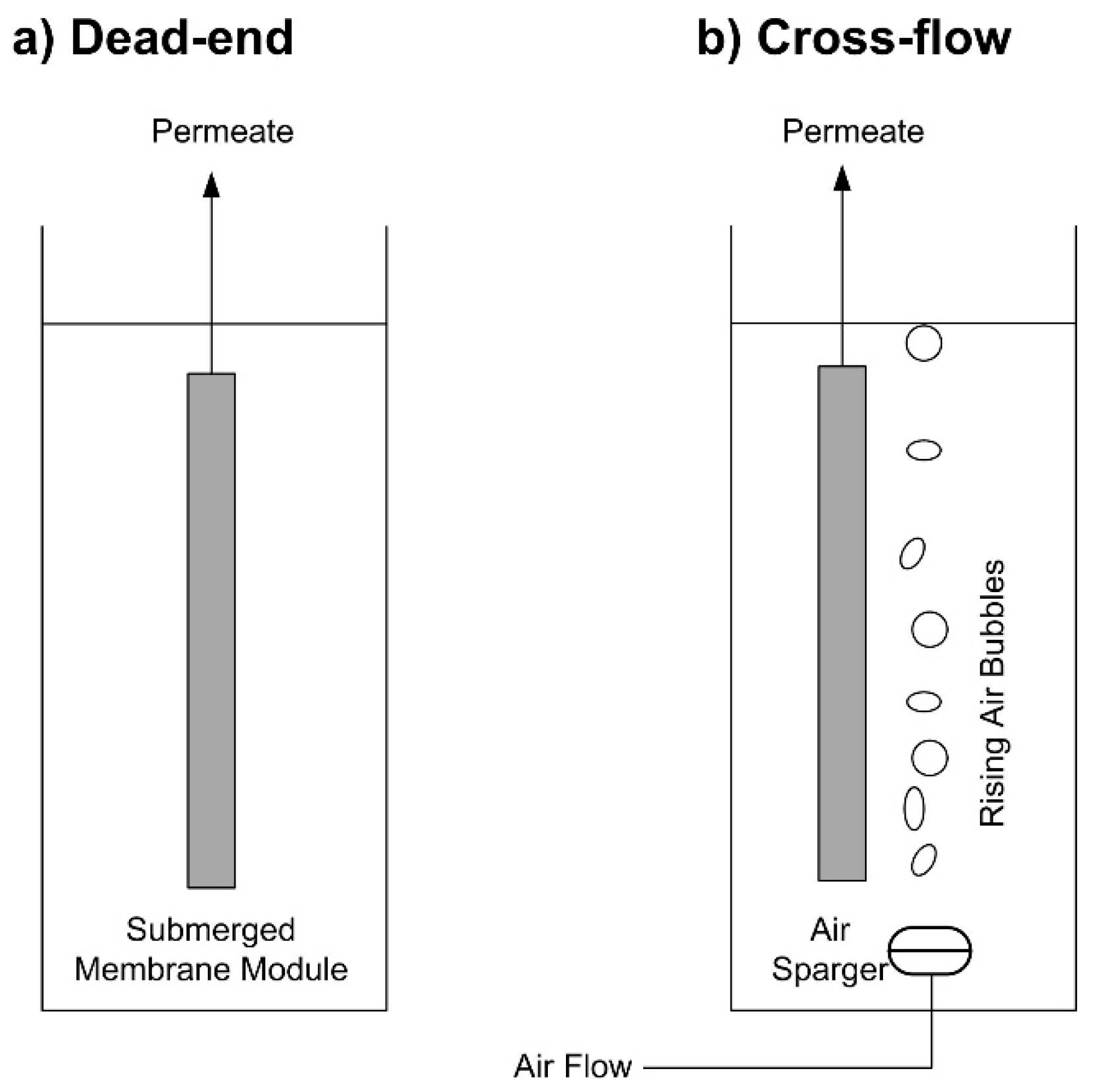
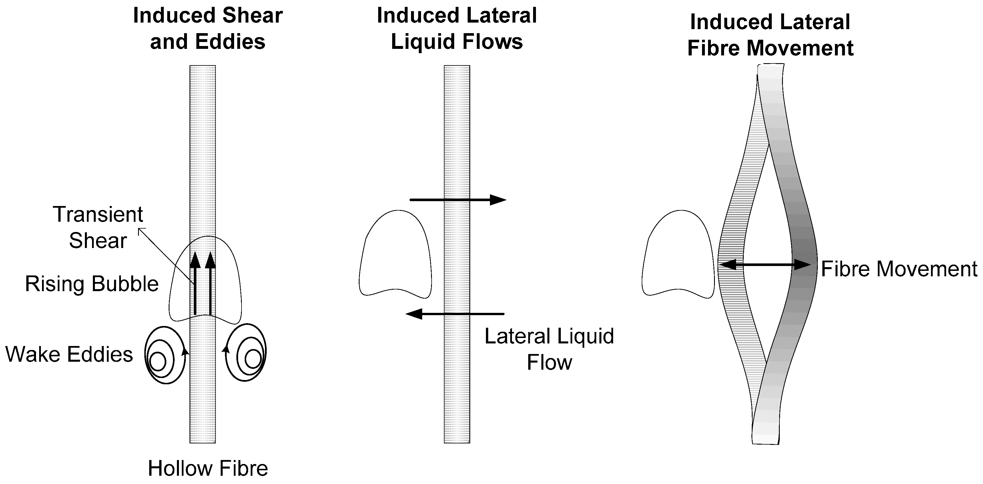
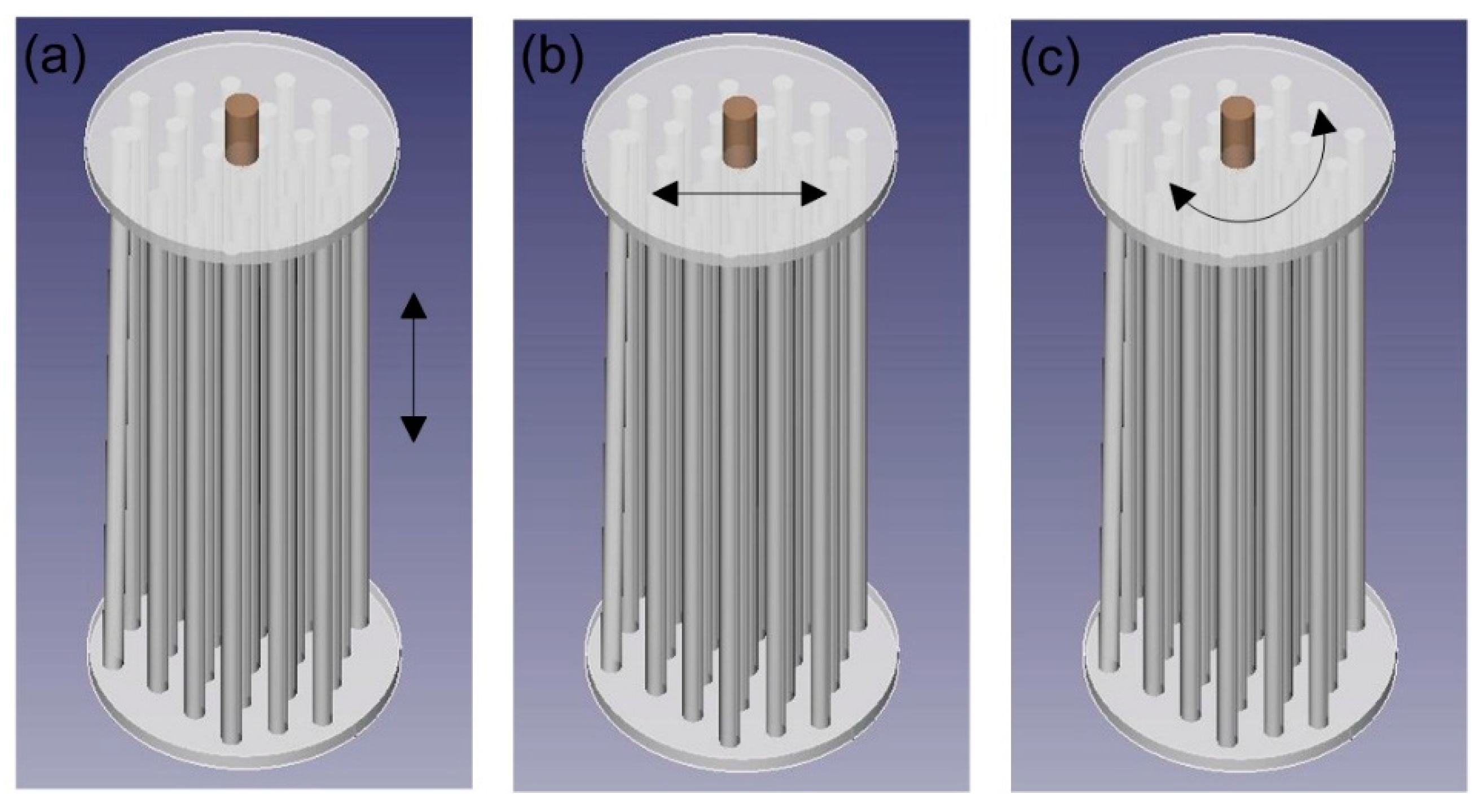
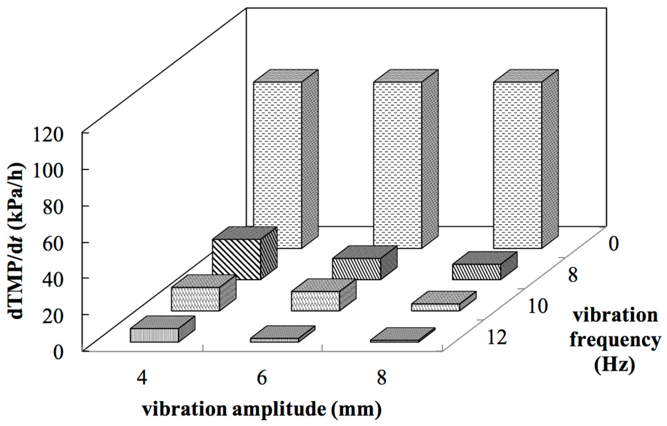
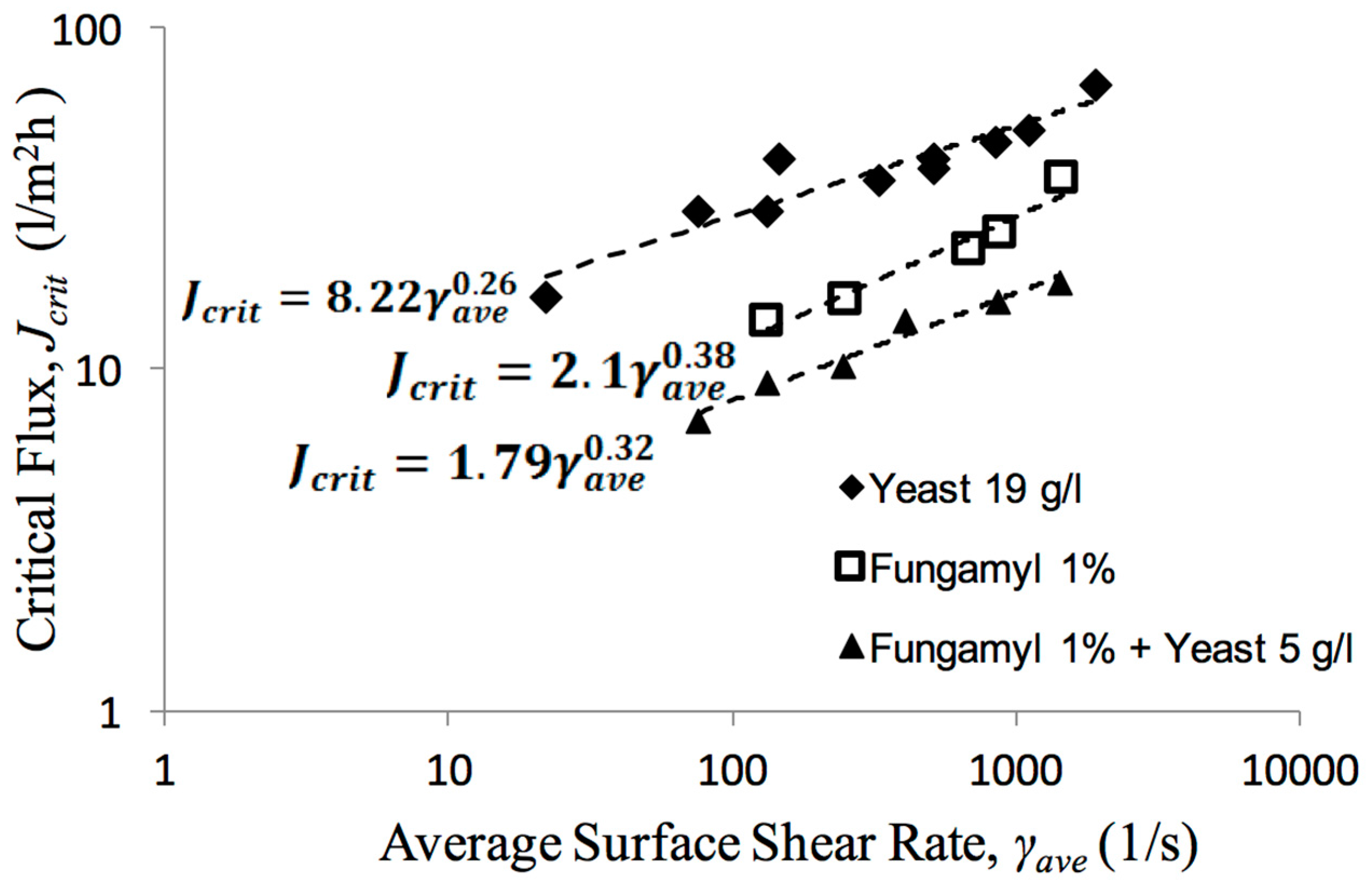
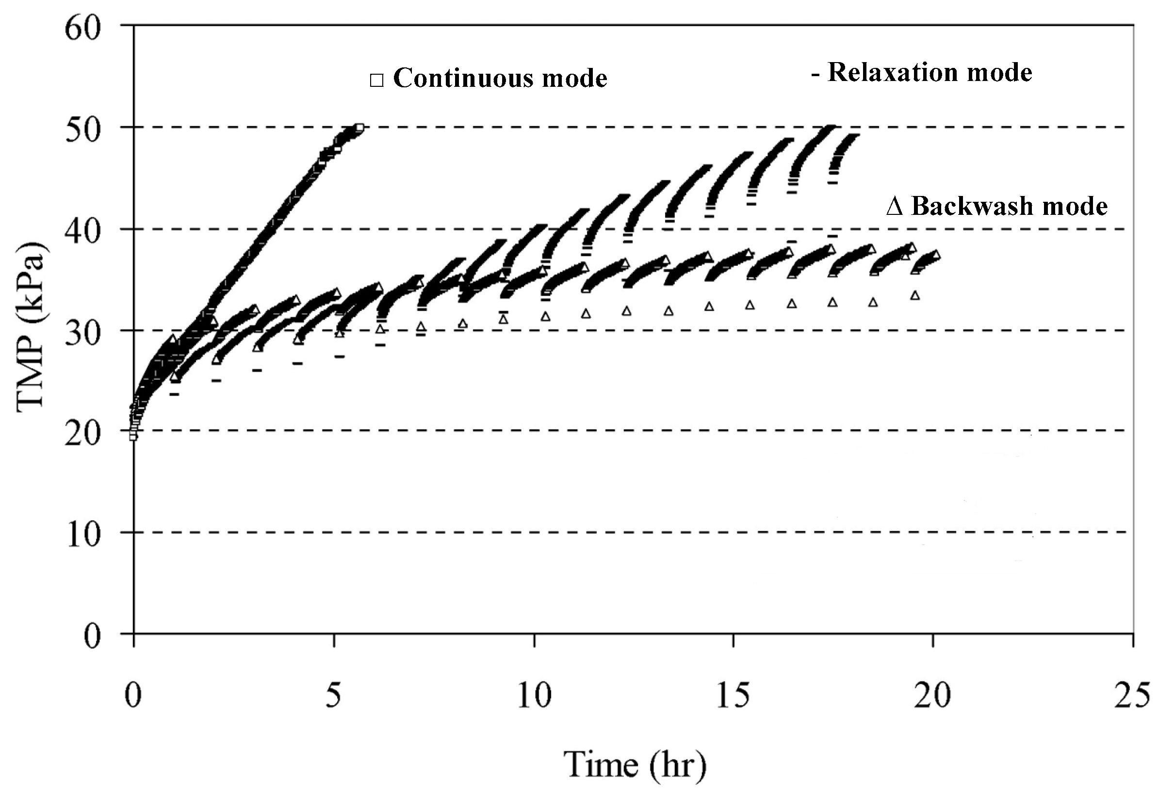
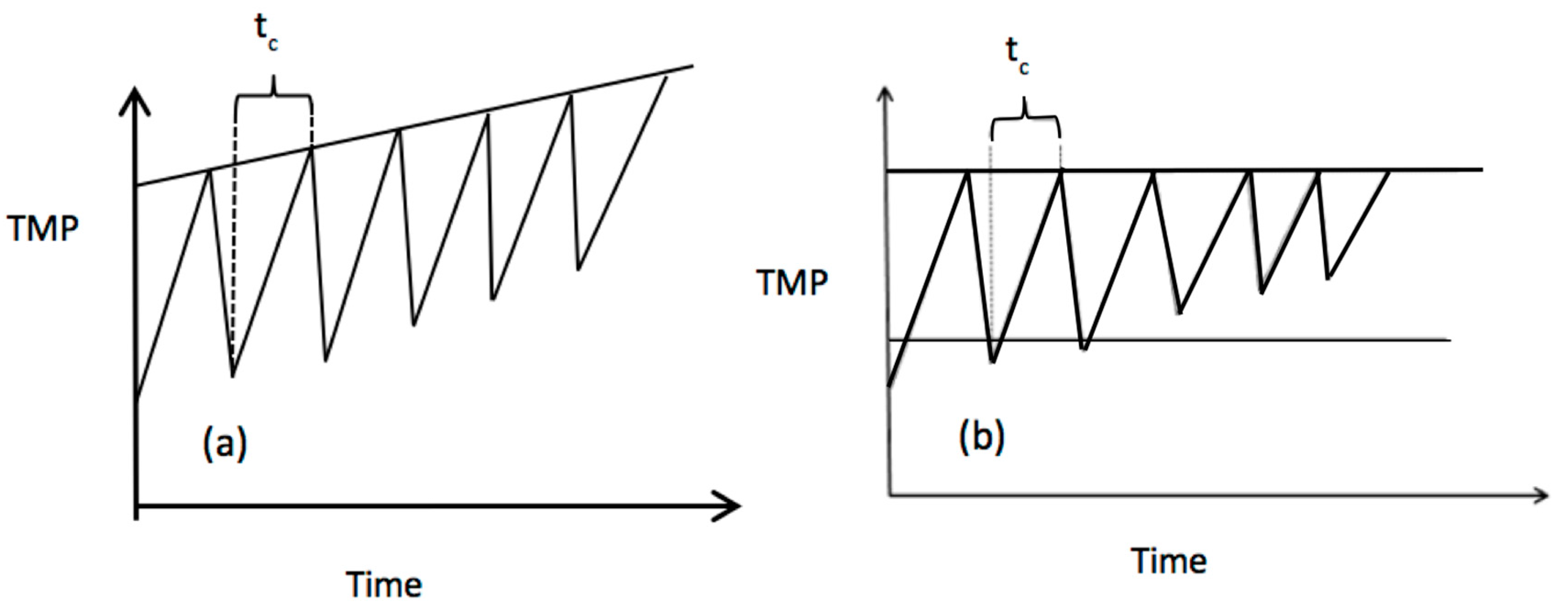
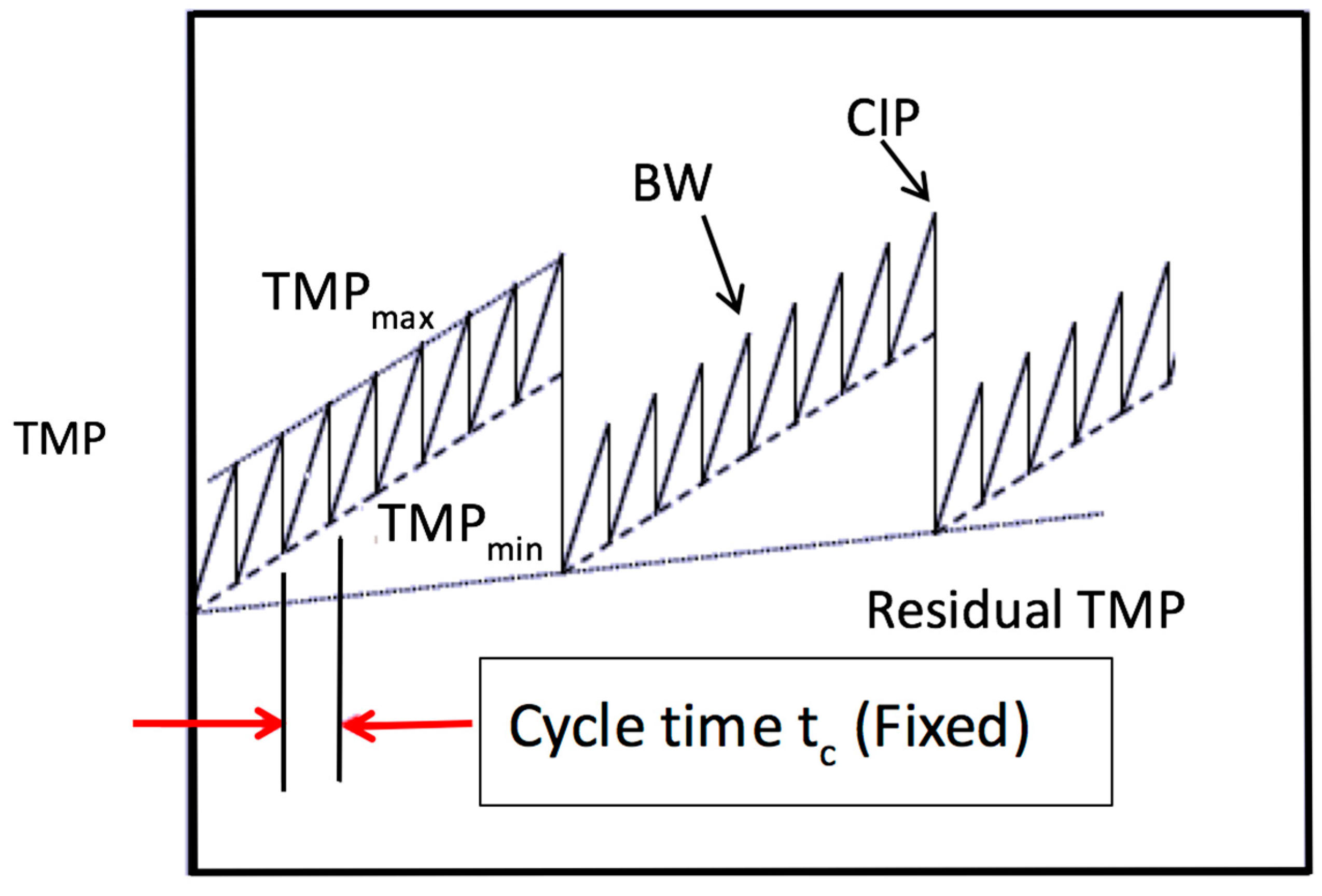
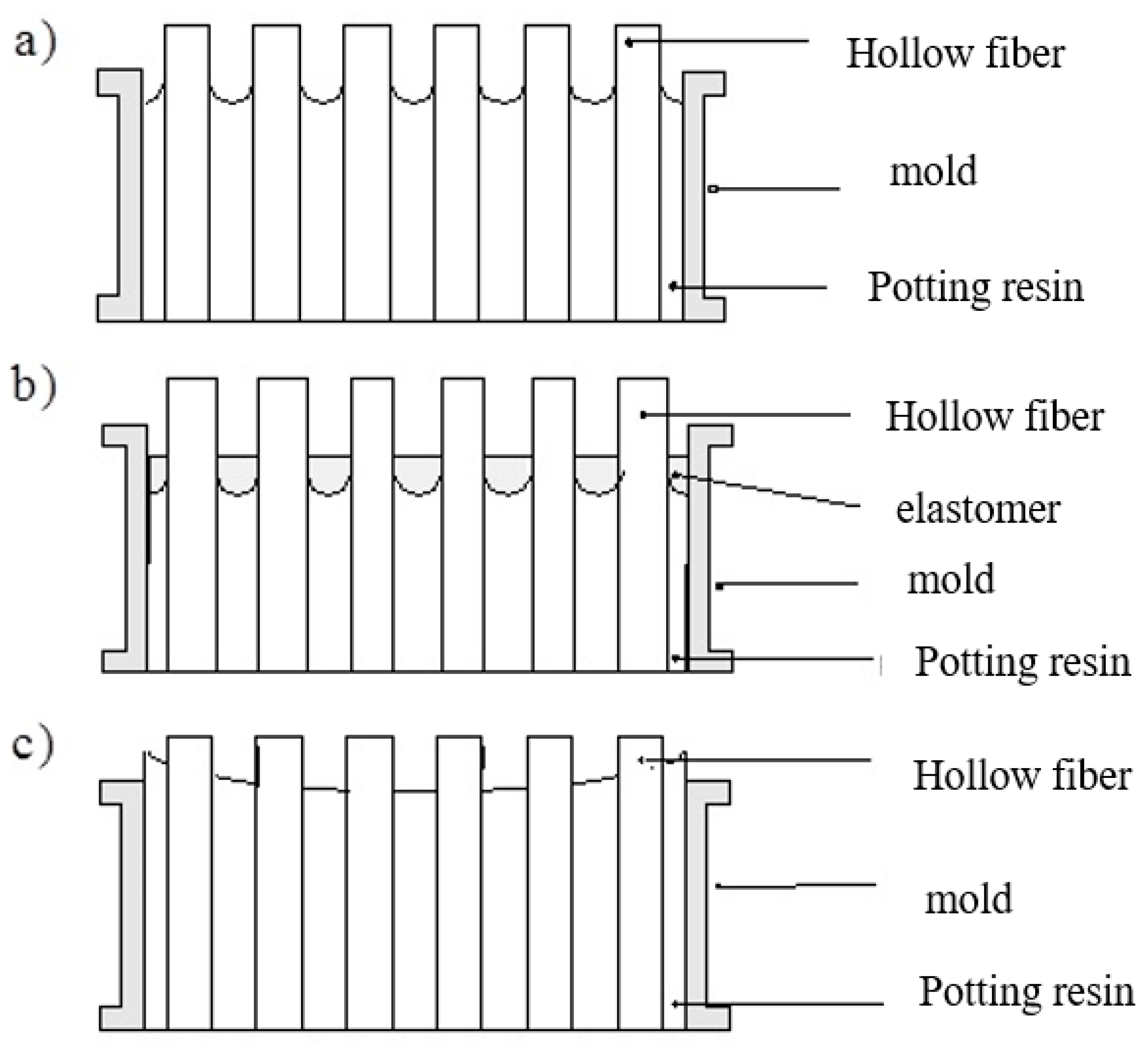
Table 1.
Submerged membrane-filtration applications and benefits.
| Application | Operation Mode | Intermittent Fouling Control | Is Bubbling Implemented? | Advantages |
|---|---|---|---|---|
| Surface-water treatment | Dead-end with intermittent foulant removal | Backwashing, relaxation, chemical cleaning | With or without bubbling during foulant removal | Less chemical requirements; consistent quality of the filtrate [35,36,37] |
| Pretreatment of RO (reverse osmosis) | Dead-end with intermittent foulant removal | Backwashing, relaxation, chemical cleaning | With or without bubbling during foulant removal | Improved water quality; smaller footprint; less chemical requirements; consistent quality of the filtrate; lowered energy cost for RO plants [38,39,40,41] |
| Membrane bioreactors (MBRs) | Cross-flow with tangential shear | Continuous bubbling, sometimes backwash and relaxation | Continuous bubbling | Small footprint; complete solid-liquid separation; high volumetric organic removal rate; higher effluent quality [19,20,42] |
| Operation Mode | Fouling Control Technique | Important Parameters | Applications | Benefits |
|---|---|---|---|---|
| Cross-flow | Bubbling | Bubble characteristics, gas flowrate, bubbling modes (intermittent or continuous) | MBR, AnMBR | Unsteady or transient shear stress; changes biomass properties |
| Vibration | Vibration amplitude and frequency | AnMBR, MF, UF, MD, FO | Low energy cost; surface shear; effective cake removal; facilitates separation of macromolecules | |
| Particle Scouring | Size, fluidization rate | AFBR-AFMBR, IAFMBR | Reduced fouling; low energy cost; amenability for scale-up (disadvantages: membrane damage, blockage) | |
| Dead-end | Backwashing | Backwash flux, backwash duration, backwash frequency | All HF systems | Internal fouling control; can be applied with air scouring |
| Relaxation | Relaxation duration, relaxation frequency | All HF systems, especially MBR | - |
AnMBR: anaerobic membrane bioreactor; MF: microfiltration; UF: ultrafiltration; MD: membrane distillation; FO: forward osmosis; AFBR-AFMBR: anaerobic fluidized-bed bioreactor-anaerobic fluidized-bed membrane bioreactor; IAFMBR: integrated anaerobic fluidized-bed membrane bioreactor.
© 2017 by the authors. Licensee MDPI, Basel, Switzerland. This article is an open access article distributed under the terms and conditions of the Creative Commons Attribution (CC BY) license (http://creativecommons.org/licenses/by/4.0/).
Share and Cite
MDPI and ACS Style
Akhondi, E.; Zamani, F.; Tng, K.H.; Leslie, G.; Krantz, W.B.; Fane, A.G.; Chew, J.W. The Performance and Fouling Control of Submerged Hollow Fiber (HF) Systems: A Review. Appl. Sci. 2017, 7, 765. https://doi.org/10.3390/app7080765
AMA Style
Akhondi E, Zamani F, Tng KH, Leslie G, Krantz WB, Fane AG, Chew JW. The Performance and Fouling Control of Submerged Hollow Fiber (HF) Systems: A Review. Applied Sciences. 2017; 7(8):765. https://doi.org/10.3390/app7080765
Chicago/Turabian StyleAkhondi, Ebrahim, Farhad Zamani, Keng Han Tng, Gregory Leslie, William B. Krantz, Anthony G. Fane, and Jia Wei Chew. 2017. "The Performance and Fouling Control of Submerged Hollow Fiber (HF) Systems: A Review" Applied Sciences 7, no. 8: 765. https://doi.org/10.3390/app7080765
Note that from the first issue of 2016, this journal uses article numbers instead of page numbers. See further details here.