Transition Analysis and Its Application to Global Path Determination for a Biped Climbing Robot


Abstract
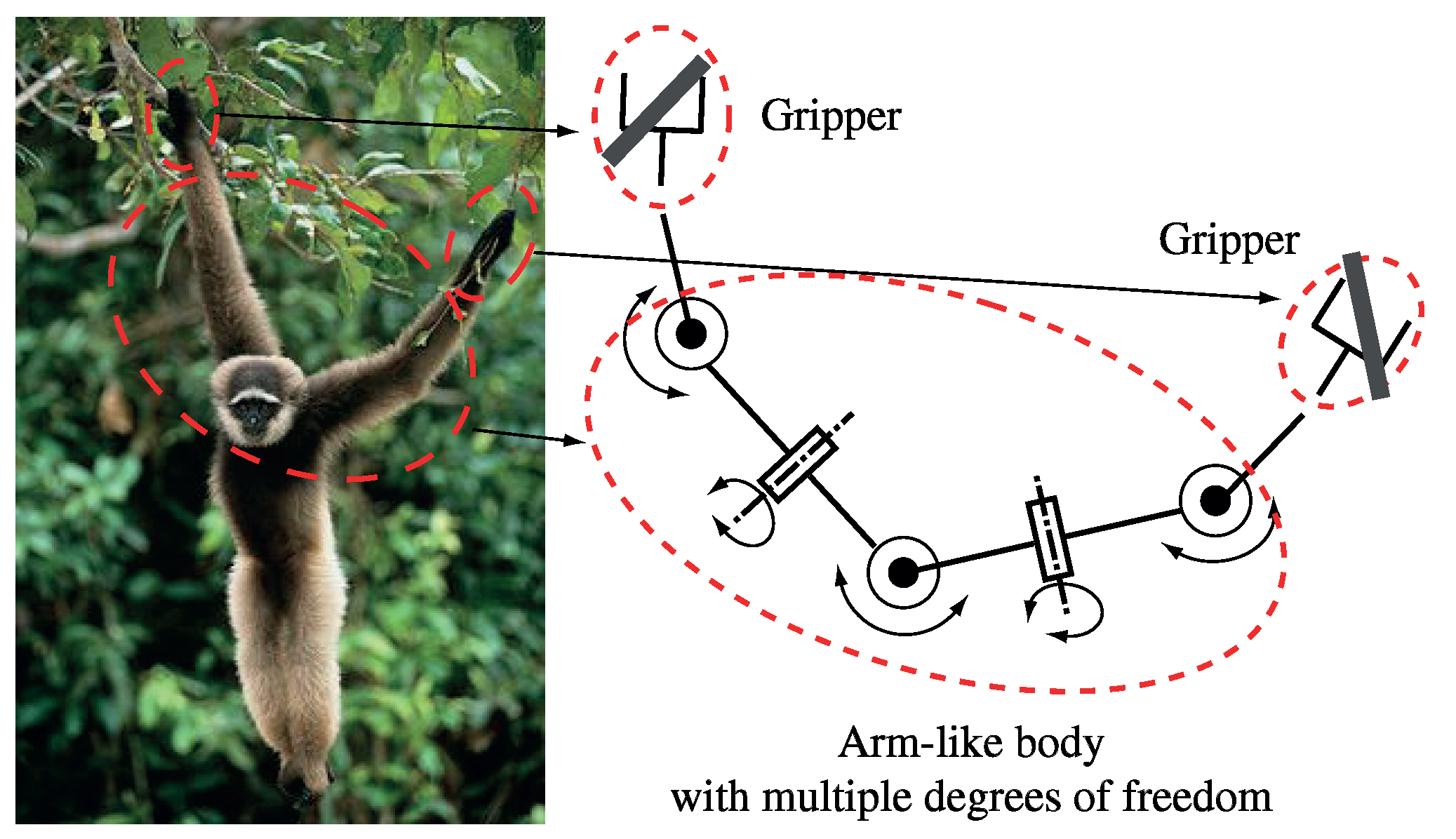
:1. Introduction
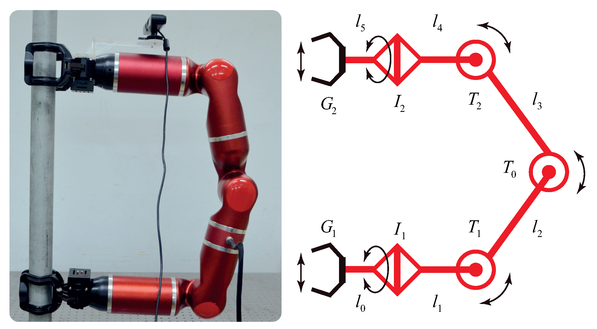
2. Problem Statement
2.1. Global Path for Traveling on Trusses
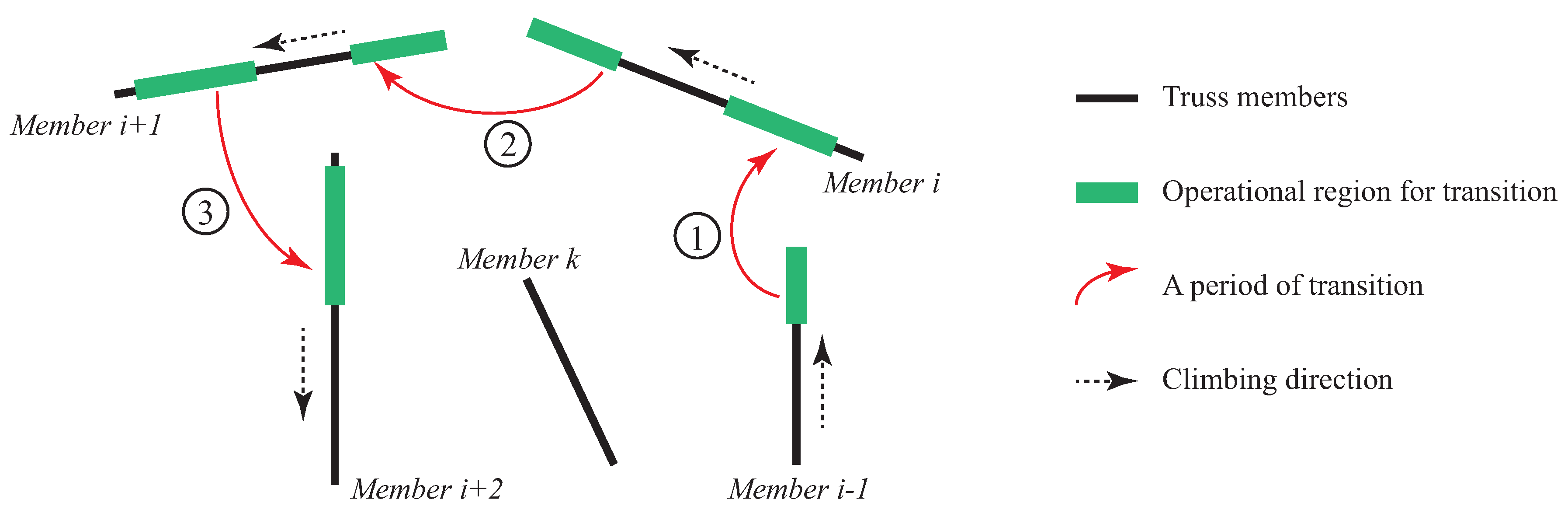
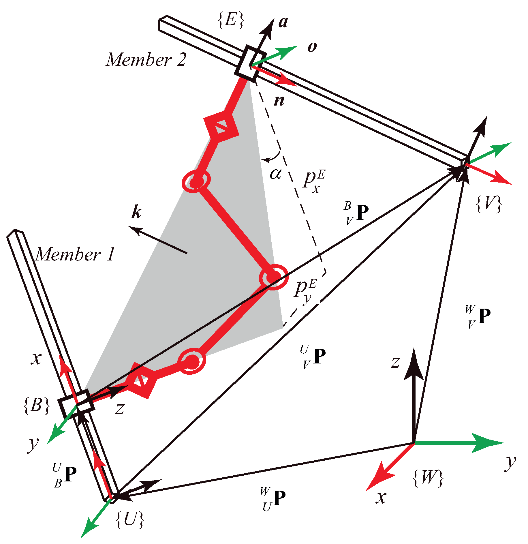
2.2. Transition from One Member to Another
- (a)
- The robot starts to move its end effector, i.e., the swinging gripper, towards Member 2, as indicated in Figure 4a.
- (b)
- After aligning well with Member 2, the robot shifts its swinging gripper to the desired gripping point, as shown in Figure 4b.
- (c)
- The robot grips on Member 2 with its swinging gripper and holds the two members at the same time, as shown in Figure 4c.
- (d)
- The robot releases the base gripper from Member 1. Afterwards the two grippers alternate their roles.
- (e)
- The new swinging gripper moves away from Member 1, then towards its new target gripping point. Procedures (d) and (e) correspond to Figure 4d.
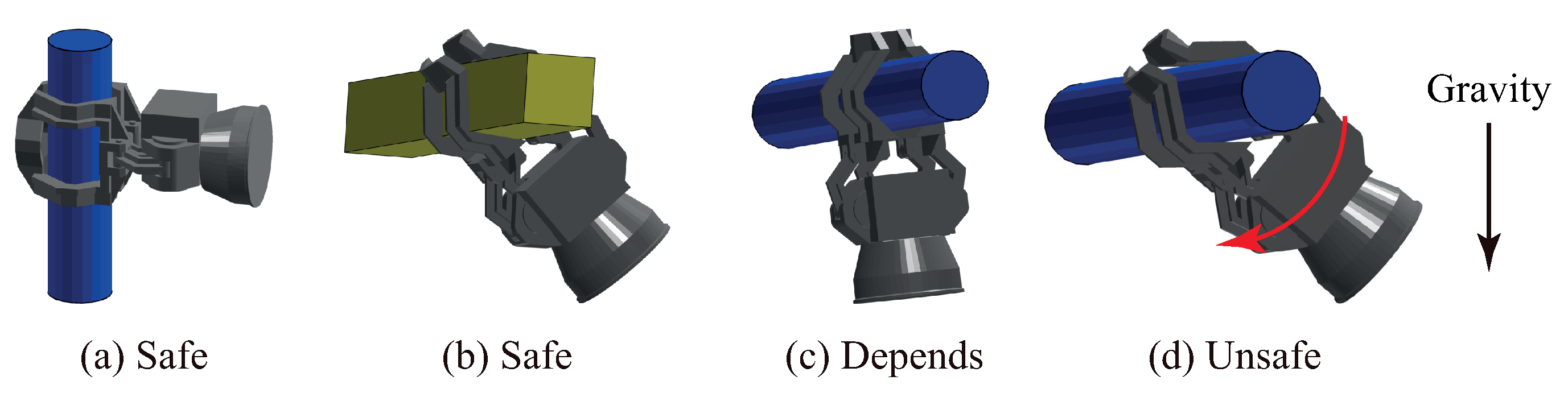
- Safety. The robot must be able to support itself reliably with only one grip, as required in phases (a)–(e), respectively.
- Reachability. The robot must be able to simultaneously grip both members with its two grippers, satisfying kinematic constraints, as illustrated in phase (c).
- Accessibility. Grips on both members must be accessible by corresponding grippers, as required in phases (b) and (e). Each grip’s accessibility must be considered in two aspects: when the gripper moves towards the grip, and when the gripper moves away from the grip after alternating its role. Considering the envelope pattern used, possibilities for the gripper moving forwards and backwards with respect to a grip in the gripping direction for a specified safe distance, are accounted the corresponding grip’s accessibility.
| Given: | Points on Member 1 | |
| Points on Member 2 | ||
| Current gripping orientation | ||
| Goal gripping orientation | ||
| Robot inverse kinematics | ||
| To solve: | and | Operational regions for transition satisfying Equations (1) to (4) |
3. Transition Analysis
3.1. Preliminary Requirements
3.2. Strict Constraints
3.2.1. Orientation Constraints
3.2.2. Position Constraints
3.2.3. Length Constraints
3.2.4. Other Constraints
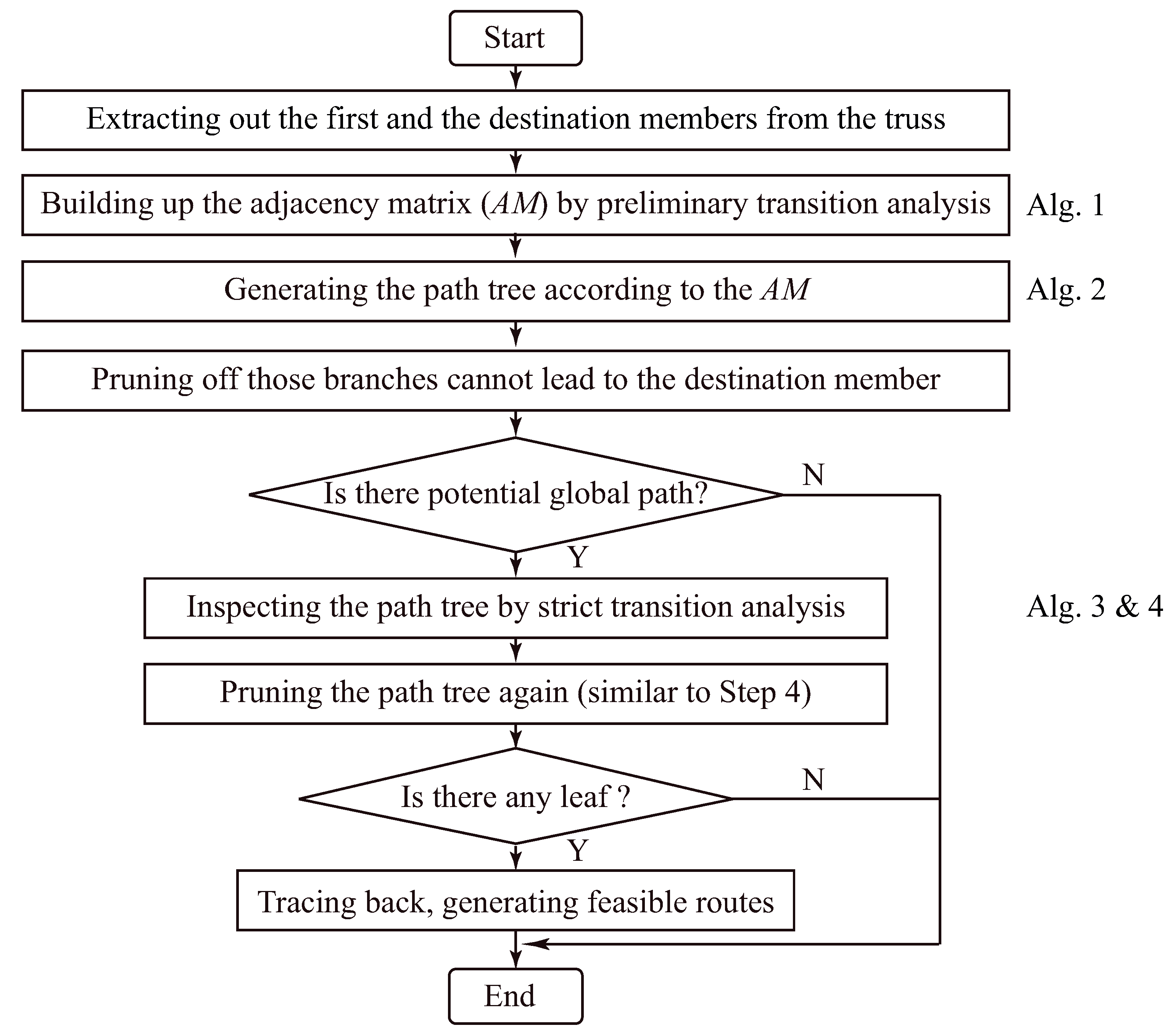
4. Fast Determination of Feasible Global Paths
4.1. Principle and Flowchart
- Never go backwards.
- Stop going forwards only when either the destination member is reached or there is no member that it has never been to.
| Algorithm 1: Building up the adjacency matrix |
| Input: : the truss; : lengths of robot linkages. Output: : the adjacency matrix.
|
| Algorithm 2: Generating the path tree |
| Input: : the adjacency matrix; : the member the robot moving on in current iteration; : the destination member; T: the path tree from last iteration. Output: T: the path tree updated in each iteration.
|
| Algorithm 3: Inspecting the path tree |
| Input: : the truss; : initial gripping orientation for base gripper; : final gripping orientation for base gripper; T: the pruned path tree from Algorithm 2. Output: : path tree with operational regions and corresponding gripping orientations.
|
4.2. Algorithms
| Algorithm 4: Solving operational regions for transition |
| Input: : reference point of Member 1; : reference point of Member 2; : gripping orientation on Member 1; : gripping orientation on Member 2; Output: : operational region for transition on Member 1; : operational region for transition Member 2;
|
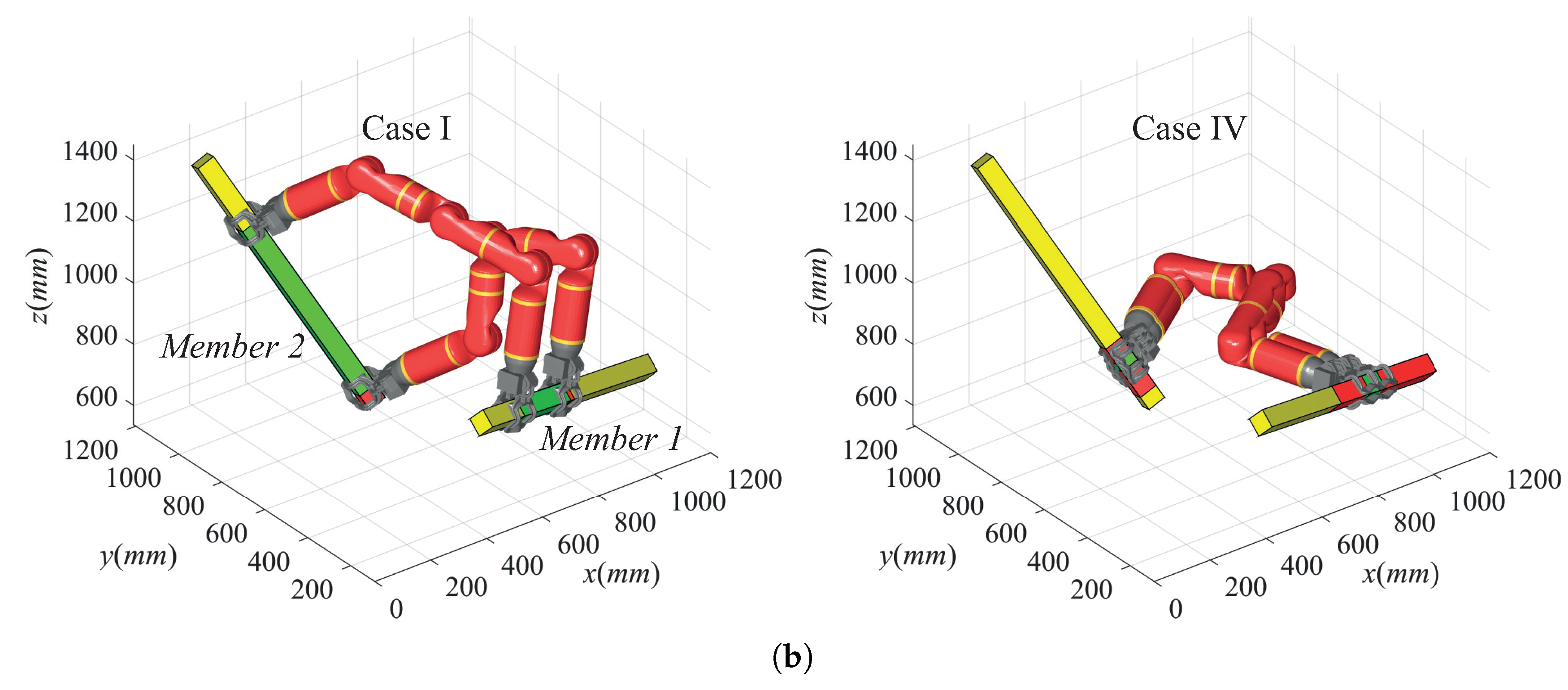
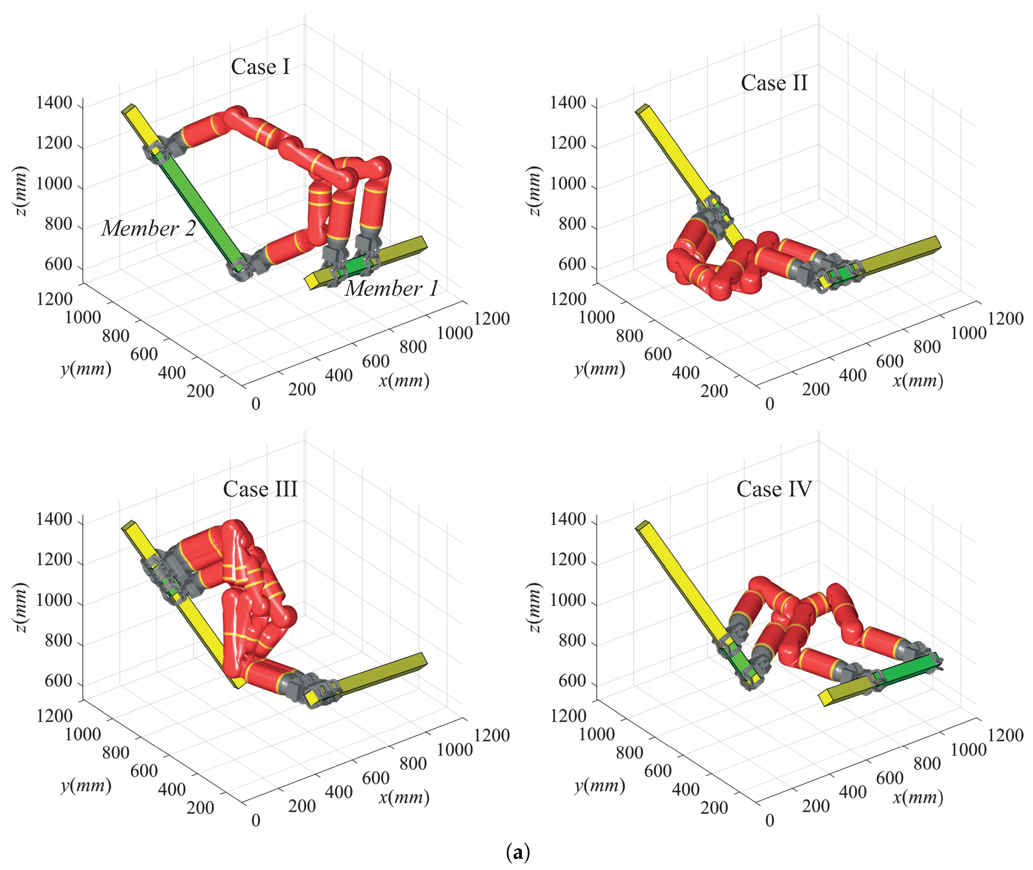
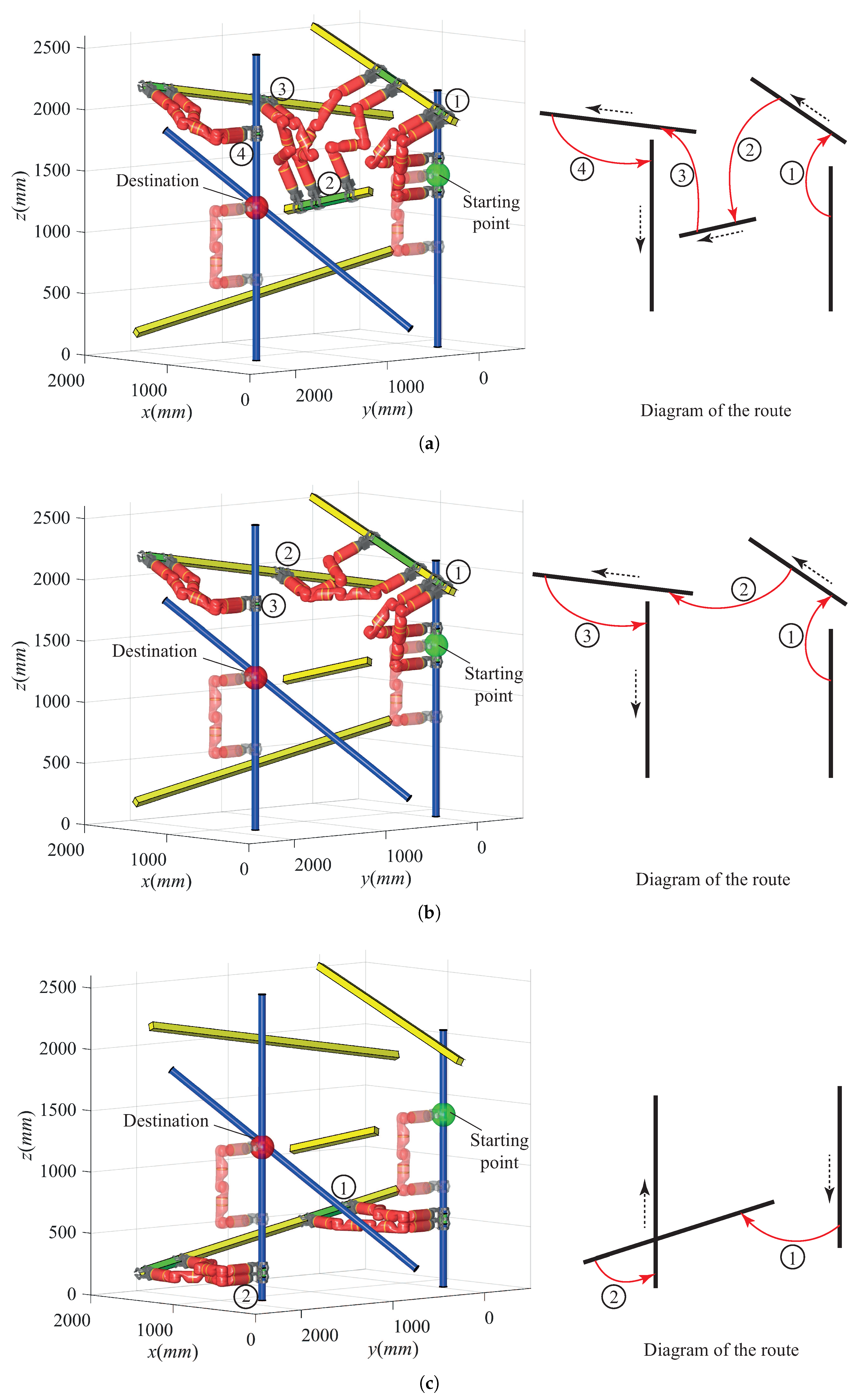
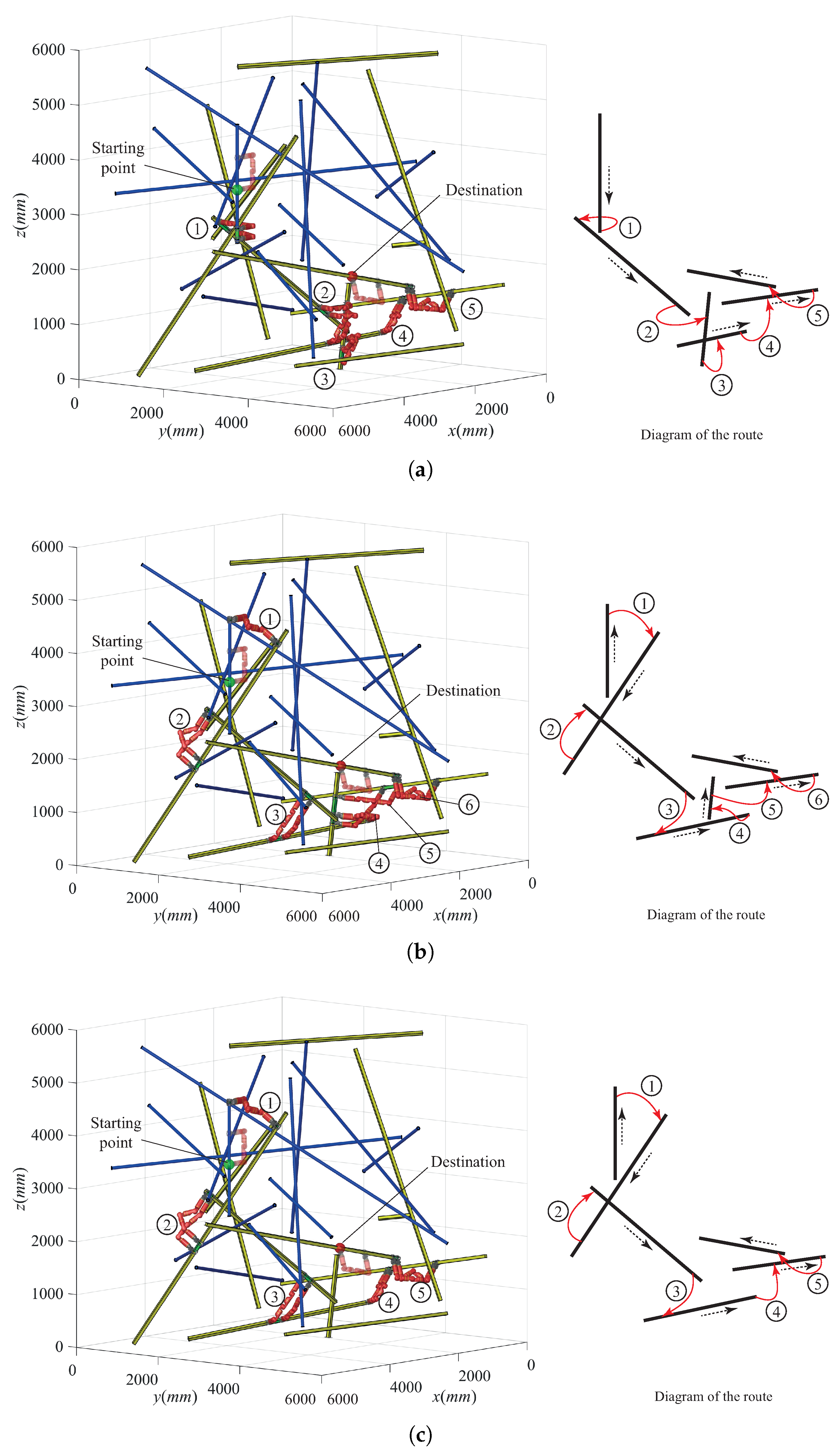
5. Simulations
5.1. Result of Transition Analysis
5.2. Result of Global Path Determination
6. Conclusions and Future Work
Acknowledgments
Author Contributions
Conflicts of Interest
References
- Xu, Y.; Brown, B.; Aoki, S.; Kanade, T. Mobility and Manipulation of a Light-weight Space Robot. Robot. Auton. Syst. 1994, 13, 1–12. [Google Scholar] [CrossRef]
- Balaguer, C.; Gimenez, A.; Pastor, J.; Padron, V.M. A Climbing Autonomous Robot for Inspection Application in 3D Complex Environments. Robotica 2000, 18, 287–297. [Google Scholar] [CrossRef]
- Nakanishi, J.; Fukuda, T.; Koditschek, D.E. A Brachiating Robot Controller. IEEE Trans. Robot. Autom. 2000, 16, 109–123. [Google Scholar] [CrossRef]
- Saltaren, R.; Aracil, R.; Reinoso, O.; Scarano, M. Climbing Parallel Robot: A Computational and Experimental Study of its Performance around Structural Nodes. IEEE Trans. Robot. 2005, 21, 16–22. [Google Scholar] [CrossRef]
- Aracil, R.; Saltaren, R.; Reinoso, O. A Climbing Parallel Robot: A Robot to Climb along Tubular and Metallic Structures. IEEE Robot. Autom. Mag. 2006, 13, 16–22. [Google Scholar] [CrossRef]
- Kushihashi, Y.; Koji, Y.; Yoshikawa, K. Development of Tree-climbing and Pruning Robot WOODY-1: Simplification of Control Using Adjust Function of Grasping Power. In Proceedings of the JSME Conference on Robotics and Mechatronics, Tokyo, Japan, 26–28 May 2006; pp. 1A1-E08_1–1A1-E08_2. (In Japanese). [Google Scholar]
- Takeuchi, M.; Namba, H.; Suga, Y.; Shirai, Y.; Sugano, S. Development of Street Tree Climbing Robot WOODY-2. In Proceedings of the JSME Conference on Robotics and Mechatronics, Fukuoka, Japan, 24–26 May 2009; pp. 1A2-D07_1–1A2-D07_2. (In Japanese). [Google Scholar]
- Detweiler, C.; Vona, M.; Yoon, Y.; Yun, S.; Rus, D. Self-assembling Mobile Linkages. IEEE Robot. Autom. Mag. 2007, 14, 45–55. [Google Scholar] [CrossRef]
- Spenko, M.J.; Haynes, G.C.; Saunders, J.A.; Cutkosky, M.R.; Rizzi, A.A. Biologically Inspired Climbing with a Hexapedal Robot. J. Field Robot. 2008, 24, 223–242. [Google Scholar] [CrossRef]
- Haynes, G.C.; Khripin, A.; Lynch, G.; Amory, J.; Saunders, A.; Rizzi, A.A.; Koditschek, D.E. Rapid Pole Climbing with a Quadrupedal Robot. In Proceedings of the IEEE International Conference on Robotics and Automation, Kobe, Japan, 12–17 May 2009; pp. 2767–2772. [Google Scholar]
- Noohi, E.; Mahdavi, S.; Baghani, A.; Nili-Ahmadabadi, M. Wheel-Based Climbing Robot: Modeling and Control. Adv. Robot. 2010, 24, 1313–1343. [Google Scholar] [CrossRef]
- Tavakoli, M.; Marques, L.; Almeida, A. Development of an Industrial Pipeline Inspection Robot. Ind. Robot Int. J. 2010, 37, 309–322. [Google Scholar] [CrossRef]
- Lam, T.L.; Xu, Y. A Flexible Tree Climbing Robot: Treebot—Design and Implementation. In Proceedings of the IEEE International Conference on Robotics and Automation, Shanghai, China, 9–13 May 2011; pp. 5849–5854. [Google Scholar]
- Vidoni, R.; Mimmo, T.; Pandolfi, C. Tendril-Based Climbing Plants to Model, Simulate and Create Bio-Inspired Robotic Systems. J. Bionic Eng. 2015, 12, 250–262. [Google Scholar] [CrossRef]
- Guan, Y.; Jiang, L.; Zhang, X. Mechanical Design and Basic Analysis of a Modular Robot with Special Climbing and Manipulation Functions. In Proceedings of the IEEE International Conference on Robotics and Biomimetics, Sanya, China, 15–18 December 2007; pp. 502–507. [Google Scholar]
- Guan, Y.; Jiang, L.; Zhu, H.; Zhou, X.; Cai, C.; Wu, W.; Xiao, Z.; Chen, X.; Zhang, H. Climbot: A Bio-inspired Modular Biped Climbing Robot—System Development, Climbing Gaits and Experiments. ASME J. Mech. Robot. 2016, 8, 021026. [Google Scholar] [CrossRef]
- Rollinson, D.; Choset, H. Pipe Network Locomotion with a Snake Robot. J. Field Robot. 2016, 33, 322–336. [Google Scholar] [CrossRef]
- Balaguer, C.; Gimenez, A.; Jardon, A. Climbing Robots’ Mobility for Inspection and Maintenance of 3D Complex Environments. Auton. Robot. 2005, 18, 157–169. [Google Scholar] [CrossRef]
- Chu, B.; Jung, K.; Han, C.S.; Hong, D. A Survey of Climbing Robots: Locomotion and Adhesion. Int. J. Precis. Eng. Manuf. 2010, 11, 633–647. [Google Scholar] [CrossRef]
- Muscolo, G.G.; Recchiuto, C.T.; Sellers, W.; Molfino, R. Towards a Novel Embodied Robot Bio-inspired by Non-human Primates. In Proceedings of the 41st International Symposium on Robotics/Robotik 2014, Munich, Germany, 2–3 June 2014; pp. 1–7. [Google Scholar]
- Tummala, R.L.; Mukherjee, R.; Xi, N.; Aslam, D.; Dulimarta, H.; Xiao, J.; Minor, M.; Dang, G. Climbing the Walls–Presenting Two Underactuated Kinematic Designs for Miniature Climbing Robots. IEEE Robot. Autom. Mag. 2002, 9, 10–19. [Google Scholar]
- Balaguer, C.; Gimenez, A.; Huete, A.J.; Sabatini, A.M.; Topping, M.; Bolmsjo, G. The MATS Robot: Service Climbing Robot for Personal Assistance. IEEE Robot. Autom. Mag. 2006, 13, 51–58. [Google Scholar] [CrossRef]
- Chung, W.; Xu, Y. A Novel Frame Climbing robot: Frambot. In Proceedings of the IEEE International Conference on Robotics and Biomimetics, Phuket, Thailand, 7–11 December 2011; pp. 2559–2566. [Google Scholar]
- Guan, Y.; Zhu, H.; Wu, W.; Zhou, X.; Jiang, L.; Cai, C.; Zhang, L.; Zhang, H. A Modular Biped Wall-Climbing Robot with High Mobility and Manipulating Function. IEEE/ASME Trans. Mechatron. 2013, 18, 1787–1798. [Google Scholar] [CrossRef]
- Silva, M.F.; Machado, J.A.T. A Survey of Technologies and Applications for Climbing Robots Locomotion and Adhesion. In Climbing and Walking Robots; InTech: London, UK, 2010; pp. 1–22. [Google Scholar]
- Schmidt, D.; Berns, K. Climbing Robots for Maintenance and Inspections of Vertical Structures—A Survey of Design Aspects and Technologies. Robot. Auton. Syst. 2013, 61, 1288–1305. [Google Scholar] [CrossRef]
- Yoon, Y.; Rus, D. Shady3D: A Robot that Climbs 3D Trusses. In Proceedings of the IEEE International Conference on Robotics and Automation, Roma, Italy, 10–14 April 2007; pp. 4071–4076. [Google Scholar]
- Chung, W.; Xu, Y. Minimum Energy Demand Locomotion on Space Station. J. Robot. 2013, 2013, 723535. [Google Scholar] [CrossRef]
- Cai, C.; Zhu, H.; Guan, Y.; Zhang, X.; Zhang, H. A Biologically Inspired Miniature Biped Climbing Robot. In Proceedings of the IEEE International Conference on Mechatronics and Automation, Changchun, China, 9–12 August 2009; pp. 2653–2658. [Google Scholar]
- Cai, C.; Guan, Y.; Zhou, X.; Jiang, L.; Zhu, H.; Wu, W.; Zhang, X.; Zhang, H. Joystick-based Control for a Biomimetic Biped Climbing Robot. Robot 2012, 34, 363–368. (In Chinese) [Google Scholar] [CrossRef]
- Zhu, H.; Guan, Y.; Wu, W.; Chen, X.; Zhou, X.; Zhang, H. A Binary Approximating Method for Graspable Region Determination of Biped Climbing Robots. Adv. Robot. 2014, 28, 1405–1418. [Google Scholar] [CrossRef]
- Xu, Y.; Brown, B.; Kanade, T. Control Systems of the Self-Mobile Space Manipulator. IEEE Trans. Control Syst. Technol. 1994, 2, 207–219. [Google Scholar]
- Yun, S.; Rus, D. Optimal Self Assembling of Modular Manipulators with Active and Passive Modules. Auton. Robot. 2011, 31, 183–207. [Google Scholar] [CrossRef]
- Lam, T.; Xu, Y. Motion Planning for Tree Climbing with Inchworm-like Robots. J. Field Robot. 2013, 30, 87–101. [Google Scholar] [CrossRef]
- Zhu, H.; Guan, Y.; Wu, W.; Zhou, X.; Zhang, H. Transition Analysis of a Biped Pole-Climbing Robot—Climbot. In Proceedings of the 16th International Conference on Climbing and Walking Robots, Sydney, Australia, 14–17 July 2012; pp. 685–692. [Google Scholar]


| Discriminants a | Distribution b | Operational Regions |
|---|---|---|
| Out of the workspace | No | |
| , | Out of the rotation limitation | No |
| , | On the boundary of the workspace | Unique point |
| , | Within the workspace and rotation limitation | One segment |
| , | Within the workspace but some points beyond rotation limitation of | Two segments c |
| Characteristics | Operational Regions a | Shortening Percentage b | |
|---|---|---|---|
| On Member 1 | On Member 2 | ||
| Case I | |||
| Without | |||
| With | |||
| Case II | |||
| Without | |||
| With | \ | \ | |
| Case III | |||
| Without | |||
| With | \ | \ | |
| Case IV | |||
| Without | |||
| With | |||
© 2018 by the authors. Licensee MDPI, Basel, Switzerland. This article is an open access article distributed under the terms and conditions of the Creative Commons Attribution (CC BY) license (http://creativecommons.org/licenses/by/4.0/).
Share and Cite
Zhu, H.; Gu, S.; He, L.; Guan, Y.; Zhang, H. Transition Analysis and Its Application to Global Path Determination for a Biped Climbing Robot. Appl. Sci. 2018, 8, 122. https://doi.org/10.3390/app8010122
Zhu H, Gu S, He L, Guan Y, Zhang H. Transition Analysis and Its Application to Global Path Determination for a Biped Climbing Robot. Applied Sciences. 2018; 8(1):122. https://doi.org/10.3390/app8010122
Chicago/Turabian StyleZhu, Haifei, Shichao Gu, Li He, Yisheng Guan, and Hong Zhang. 2018. "Transition Analysis and Its Application to Global Path Determination for a Biped Climbing Robot" Applied Sciences 8, no. 1: 122. https://doi.org/10.3390/app8010122
APA StyleZhu, H., Gu, S., He, L., Guan, Y., & Zhang, H. (2018). Transition Analysis and Its Application to Global Path Determination for a Biped Climbing Robot. Applied Sciences, 8(1), 122. https://doi.org/10.3390/app8010122