Agile Attitude Control and Singularity Avoidance/Escape by the SDRE Method Using a Biased State-Dependent Weighting Matrix


1
School of Science for Open and Environmental Systems, Graduate School of Science and Technology, Keio University, 3-14-1 Hiyoshi, Kohoku-ku, Yokohama 223-8522, Japan
2
Department of System Design Engineering, Faculty of Science and Technology, Keio University, 3-14-1 Hiyoshi, Kohoku-ku, Yokohama 223-8522, Japan
*
Author to whom correspondence should be addressed.
Appl. Sci. 2018, 8(1), 140; https://doi.org/10.3390/app8010140
Submission received: 12 December 2017
/
Revised: 16 January 2018
/
Accepted: 17 January 2018
/
Published: 19 January 2018
(This article belongs to the Section Mechanical Engineering)
Abstract
:In recent years there has been an increasing need to improve satellite attitude control performance in terms of agility and attitude accuracy in large-angle attitude maneuvers. To achieve such control performance, single-gimbal control moment gyros (SGCMGs) should be mounted as modern-type actuators. Conventionally, based on the torque command calculated by the attitude control system of the satellite, SGCMGs were controlled by solving inverse kinematics through a pseudo inverse matrix steering law. However, in such a control system structure, it may be difficult to obtain the desired torque required by the attitude control system because of the singularity problem of SGCMGs. Furthermore, with respect to implementation, since the condition number of the Jacobian matrix of SGCMG becomes extremely large in the singularity, the numerical calculation error of the pseudo inverse matrix increases greatly. Therefore, we propose an overall control system that can solve above-described problems and the state-dependent Riccati equation (SDRE) control system that integrates the satellite and SGCMG system. The proposed optimal control system, which does not solve the pseudo inverse matrix, can realize gimbal angle guidance by gimbal angle feedback and singularity avoidance/escape using the biased weighting matrix. In the numerical simulation, the usefulness of proposed system is shown in comparison with the conventional system.

1. Introduction
In recent years, there has been a growing demand for earth observation satellites equipped with highly accurate observation sensors to capture high-resolution images of certain points on the ground. For example, earth observation satellites including IKONOS which is launched in 1999, have made emergency observations to determine the detailed situation of disaster areas, and made efforts to utilize this information to prevent secondary disasters and aid in prompt reconstruction. In order to direct the sensors to the ground in comparison with sweeping the earth’s surface, such earth observation satellites need to improve their agility in large-angle attitude maneuvers. Moreover, methods that enable highly accurate attitude determination by online sensors such as the star tracker (ST) and inertial measurement unit (IMU), as well as global positioning system (GPS) based methods [1,2] have been proposed. Thus, high accuracy of attitude control is also needed using this information.
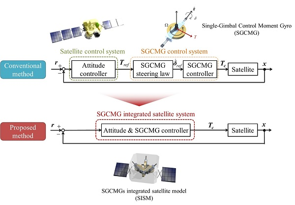
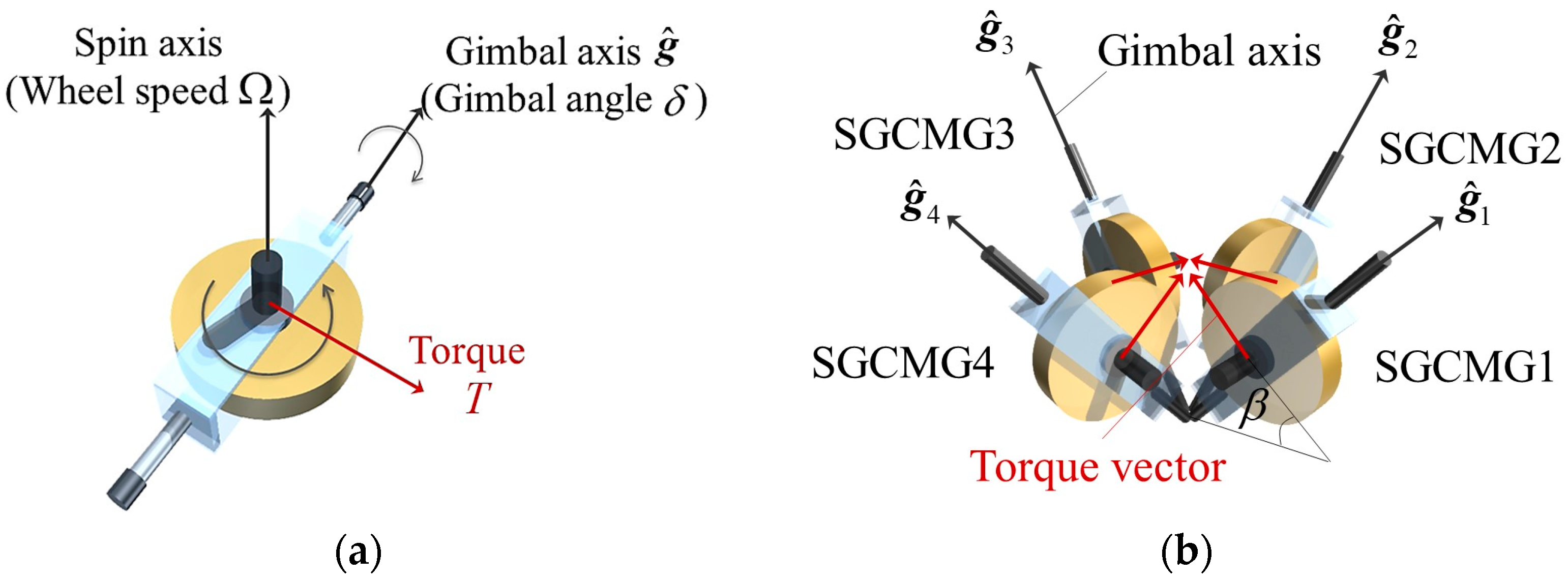
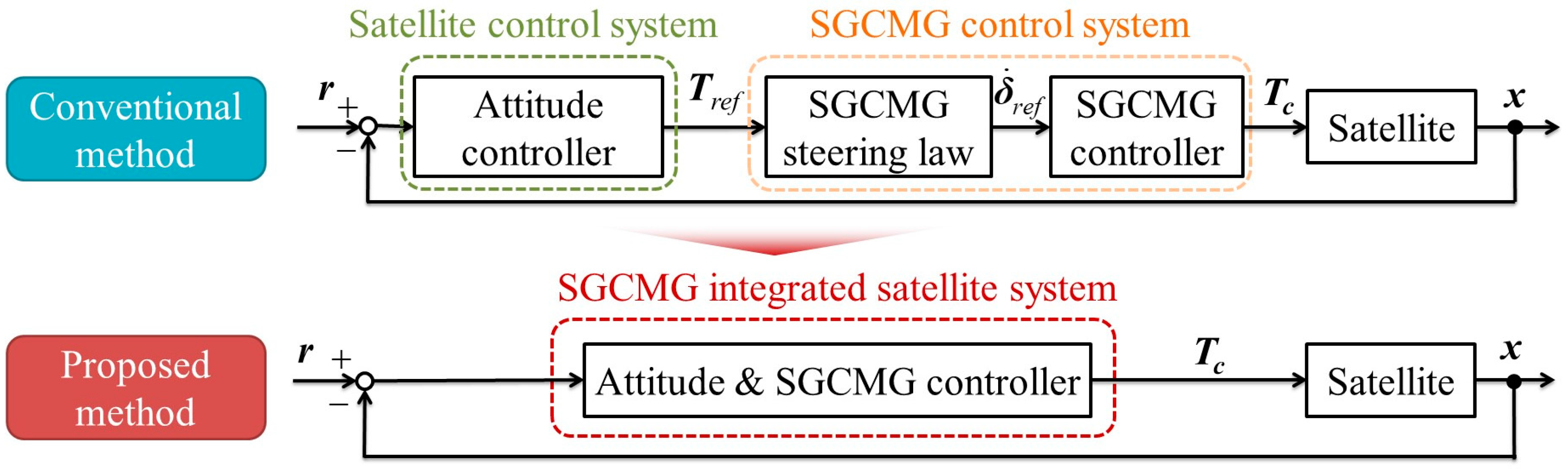
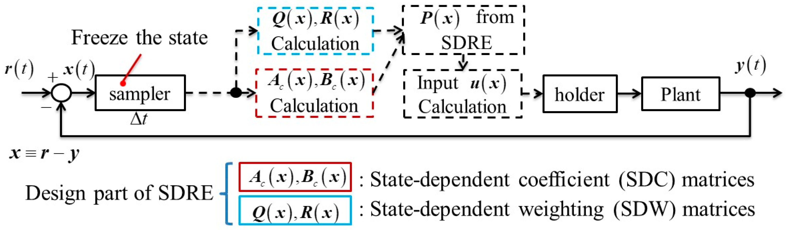
To achieve the above-described agile large-angle attitude maneuver, a single-gimbal control moment gyro (SGCMG) should be mounted as a modern-type actuator. The SGCMG (as shown in Figure 1a) is an internal force actuator that outputs a large torque owing to the gyro effect generated by rotating a gimbal. Normally, from the viewpoint of the redundancy and symmetry of angular momentum, the SGCMG should be equipped on a four-skew array like a pyramid, as shown in Figure 1b. In the conventional works on agile attitude maneuvers of a satellite using SGCMGs as actuators, the gimbal angular velocity is calculated by solving the pseudo inverse matrix of the SGCMGs Jacobian matrix from the torque command value calculated by the satellite attitude control system and input to the SGCMGs system (upper part of Figure 2). This control system structure has been extensively studied because of the shape of the Jacobian matrix with respect to the SGCMGs and the strong nonlinearity depending on its time variation. As usual, the singularity problem always exists for SGCMGs during the large-angle maneuvering of satellites. In the singularity, input may not be sometimes required, in which the possible output direction is degenerated owing to the combination of the gimbal angle, as shown in Figure 3. Therefore, it was necessary to design the attitude control system and the SGCMG control system separately.
As a countermeasure to the singularity problem, a number of avoidance/escape steering laws have been proposed. The singularity avoidance law of null motion by the projection matrix [3] and Jacobian cofactor [4] were firstly proposed, followed by a steering law for avoiding singularity to reduce the error of the output torque [5]. After that, a nondiagonal singularity robust steering law to escape the singular surface with torque error [6] and a generalized singularity robust (GSR) steering law [7], as well a method to make it possible to adjust the design parameters of the GSR steering law [8] were put forward. Furthermore, methods combining multiple singularity avoidance/escaping steering laws [9,10] were proposed. Subsequently, methods to avoid singularity by feed-forward inputs using a Fourier basis algorithm [11], path planning of angular momentum [12] or gimbal angle [13] appeared. In such conventional methods, it is possible that the desired control torque cannot provide output to the satellite determined by the attitude control system, and it cannot guarantee the attitude stability of the satellite under the singularity of SGCMGs. These issues caused by the singularity avoidance/escape cannot be taken into account in the attitude control system. Consequently, the possibility of adverse effects on the robustness of the attitude control system cannot be excluded.
Moreover, it is mathematically difficult to find a correct solution because the solution by the pseudo inverse method is the maximum likelihood solution, and the condition number of the matrix becomes extremely large near singularity (Jacobian matrix is ill-conditioned). Thus, an accurate solution cannot be calculated in some cases when the Jacobian matrix is ill-conditioned because calculation errors owing to round-off errors are greatly amplified [14,15]. As a countermeasure, regularization methods of the matrix for reducing calculation errors have been proposed, but the calculation costs tend to be high because repetitive calculation is necessary [14,15,16]. Considering actual operation, rounding errors are likely to be included because of the restrictions on the performance of the on-board computer. In addition, since the Jacobian matrix is time-varying, it is necessary to solve the regularization method in every control cycle. Therefore, it is considered that it is difficult to calculate an accurate solution of the pseudo inverse method in the on-board computer under a singularity where the calculation errors become large. Consequently, it is considered that a control system for calculating the control input to the SGCMGs is necessary without solving the pseudo inverse matrix.
In view of the above background, an attitude control system that can generate the gimbal angular velocity input without solving inverse kinematics (as the main control system), is required, as shown in lower part of Figure 2. Accordingly, we will integrate the satellite and SGCMGs and design a model with the gimbal angular velocity as the control input. To realize this, state-dependent linear representation (SDLR) in the state-dependent Riccati equation (SDRE) controller [17,18] is used. This proposed control system is able to gain attitude stability and robustness even in a singularity because the optimal gimbal angular velocity input is guaranteed by the SDRE controller. Furthermore, by designing SDLR with an error representation, it is possible to guide to the gimbal angle, which is advantageous for the next attitude maneuver. Additionally, singularity avoidance/escape steering is explicitly considered by taking into account the relation between the biased state-dependent weighting (BSDW) matrix for the gimbal angular velocity input and the SGCMG steering with respect to the maneuver axis. This steering of gimbals is realized by adding to each SGCMG with bias. In the numerical analysis, we verify the effectiveness of the agile large-angle attitude maneuver by the proposed control system consisting of an SGCMG-integrated satellite model (SISM) and BSDW. In addition, the analysis shows that the convergence to the target satellite attitude is guaranteed by the optimality of the gimbal angular velocity input. Furthermore, we verify the robustness against the moment of inertia which is likely to contain an error in model identification on the ground. However, a general robustness analysis of SDRE has not been determined. Therefore, as an initial study, the true values used for updating the state quantity of the plant are set in several patterns with respect to the identification values.
2. Materials and Methods
2.1. Modeling
2.1.1. Formulation of Satellite Attitude Maneuvers Using SGCMG
The satellite attitude in the body coordinate system is represented by quaternion , and time derivative is expressed by the following equation:
where is the satellite angular velocity.
The rotation of a rigid-body satellite in the body coordinate system is defined by the Euler equation including the cross product calculation “×” as follows:
where is the moment of inertia matrix of the satellite. Control torque vector is produced by the SGCMG momentum exchange. In this paper, disturbance torques are assumed to be negligible, and the nonlinear rotating dynamics of the satellite are expressed as
Now, a relation between control torque and generated torque by the SGCMG is expressed as
where is the angular momentum vector of the SGCMG. The time derivative of the angular momentum of the SGCMG is equal to the output torque , and is expressed by the following equation.
where is the angular momentum of the SGCMG wheel, is the gimbal angular velocity vector of the SGCMGs, and is a Jacobian matrix. The size of the Jacobian matrix representing how to steer the SGCMGs differs depending on the number of mountings. In this research, from the viewpoint of redundancy and the symmetry of the angular momentum, the SGCMGs should be equipped on a four-skew array like a pyramid, as shown in Figure 1b.
Therefore, the Jacobian matrix is expressed as
where is the skew angle of four SGCMGs, , and . From Equation (3) to Equation (5), the rotation of a satellite equipped with SGCMGs is expressed as
2.1.2. Singularity Problem of SGCMGs
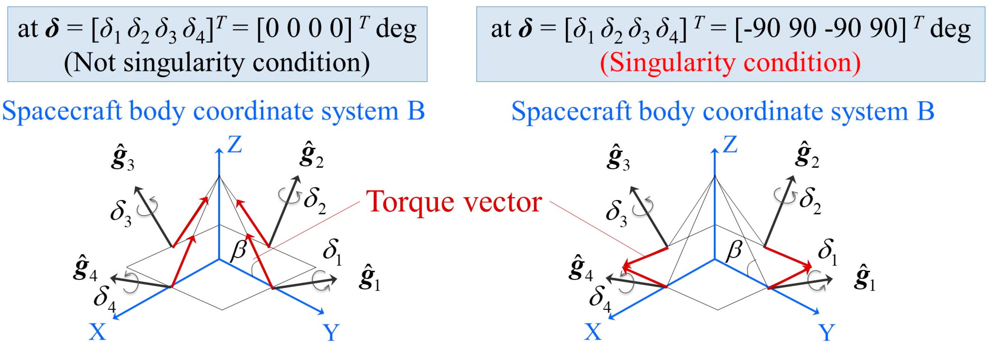
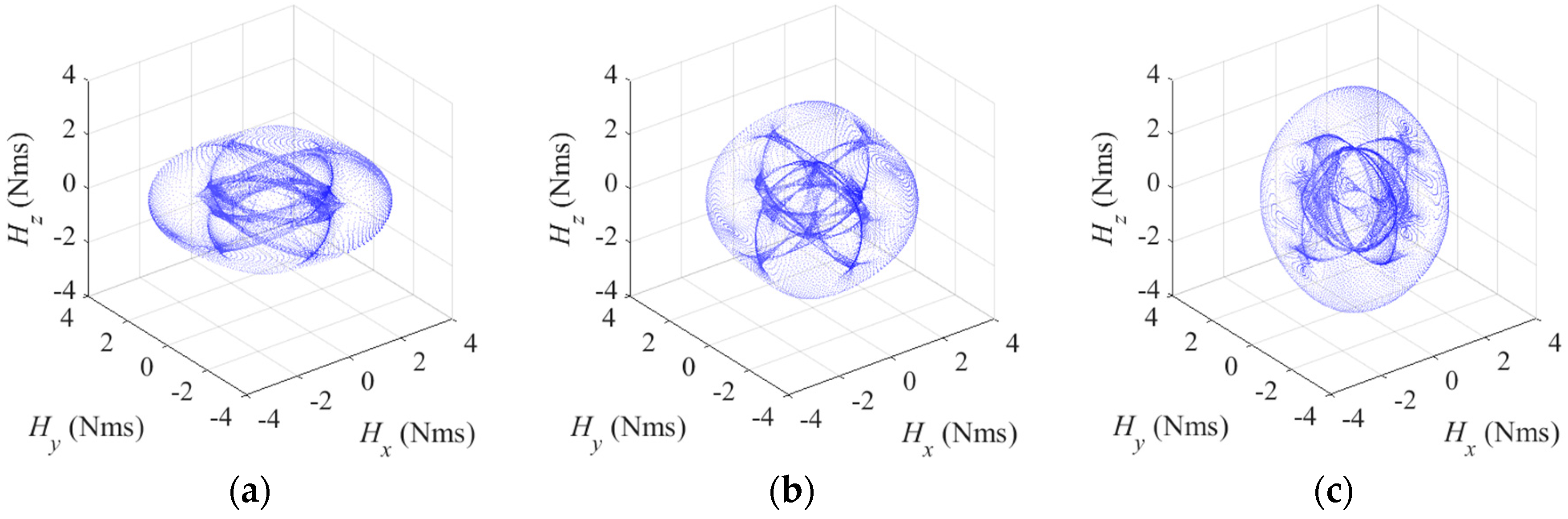
When SGCMGs are in a singularity, the direction in which torque can be output degenerates to two dimensions or fewer, as shown in Figure 3. Thus, when the attitude maneuver direction and the degenerate torque direction are the same, this adversely affects the agility of maneuver. The singularity in the dimension of angular momentum (as shown in Figure 4a–c) is expressed as
where is a singularity parameter, indicating that it is closer to a singularity when it is closer to 0. In this paper, we assume a singularity when . There are two types of singularities: internal and external. An internal singularity depends on the gimbal angle, and an external singularity occurs when the output torque is saturated at the performance limit. The external singularity is the outermost part of the singular surface, as shown in Figure 4a–c, and the internal singularity is found inside the external singularity.
Furthermore, the shape of the singular surface differs depending on the skew angle, as shown in Figure 4a–c. In actual operation, (shown in Figure 4b) is often selected from the symmetry of the angular momentum. In conventional attitude control, the gimbal angular velocity input to the SGCMG system is calculated by solving the following steering law from the torque calculated in Equation (7):
In conventional singularity avoidance/escape steering laws, an error parameter or a null vector is added to Equation (9). Such laws have been studied because the Jacobian matrix is not a square matrix and rank degenerates in the singularity. However, as the gimbal steering is not taken into consideration in the attitude controller, the robustness may be adversely affected. Thus, the design of the singularity avoidance/escape steering laws must be considered by the attitude controller.
2.2. The State-Dependent Riccati Equation (SDRE) Method
First, the nonlinear equation is given by
Let us suppose that the origin is an equilibrium point of the system. The control input is such that the following functional is minimized:
where is the state-dependent weighting (SDW) matrix of state vector , is the SDW matrix of input vector , and both of them depend on state . To design the controller, if there is an optimal index for the quadratic form evaluation function , its mathematical form can be rewritten in the form of a positive definite symmetric matrix as follows:
where a system is the SDLR, and the SDLR has a degree of freedom of modeling. Moreover, are the state-dependent coefficient (SDC) matrices that depend on state .
This procedure forms the so-called extended linearization control method. We can now define the control input such that
where is a solution of the following SDRE:
Figure 5 shows the summary of the above-described flow. In conclusion, the SDRE solution to the nonlinear regulator is a generalization of the time-invariant linear quadratic regulator (LQR) problem, where the matrices are state-dependent [18]. From an operating point of view, at each time step, the method treats SDC matrices as constants because of the “freezing” of the state. Therefore, by solving the LQR problem for each control cycle, it is possible to easily obtain the solution.
2.3. Design of Proposed Control System
2.3.1. Design of the SGCMG-Integrated Satellite Model (SISM)
In this section, we formulate the SISM [19] proposed by authors. The SISM is possible through the design of an optimal gimbal angular velocity input considering the attitude maneuver and singularity avoidance with gimbal angle guidance at the same time. To realize the SISM, the gimbal angle and gimbal angular velocity are added to the state vector to design an SDLR by error dynamics.
To design the SISM, we rewrite Equation (7) into an error representation, as follows:
where is the quaternion error vector, is the satellite angular velocity error vector, is the angular momentum error of the SGCMGs, and is the error matrix of the quaternion.
, , and are expressed as
where target angular velocity of satellite and SGCMGs angular momentum are constant values because agile observation satellite is usually operated as a rest-to-rest maneuver. Such a maneuver depends on all states being in a steady state at the initial and terminal state of the maneuver.
Therefore, Equation (15) is rewritten by Equation (12) as follows:
where is a unit matrix, is a very small negative scalar for the stability of the SDRE controller [20], is a coupling matrix between the satellite angular velocity and the moment of inertia of the satellite, and is a coupling matrix between the satellite angular velocity and the angular momentum of the SGCMG. and are defined as
To explicitly consider the singularity of SGCMGs, control torque input needs to be converted to gimbal angular velocity . Assuming that a gimbal motor is a first-order lag system with time constant , the gimbal angle error is and is defined as follows:
Therefore, the state equation of the gimbal motor of SGCMGs is expressed as
Consequently, the SISM combined Equations (5), (19), and (23) using is defined as follows:
where is another representation of and is expressed as
From the above, the optimal gimbal angular velocity input for an attitude maneuver is calculated by the SDLR of the SGCMG-integrated satellite, and this SISM is able to avoid a singularity by setting the target gimbal angle . As we mentioned above, the proposed SISM is able to explicitly design a gimbal angular velocity as a control input.
In this model, controllability is guaranteed by even under the singularity. It is necessary to verify robustness against model uncertainty by Monte Carlo analysis or the like because a formal robustness analysis of SDRE does not yet exist [18]. However, as it is the same as solving the LQR for every control cycle, it is considered that the robustness against the uncertainty of the model and stability margin have a same or higher performance to LQR.
2.3.2. Design of Biased State-Dependent Weighting (BSDW) Matrix of Input
The proposed SDLR of the SISM can explicitly design a gimbal angular velocity as a control input, and each gimbal angular velocity input can be individually designed. Therefore, we propose the BSDW matrix of for the singularity avoidance/escape via the singularity parameter , which is dependent on the gimbal angle. Here, we use the fact that the singularity parameter gets closer to 0 as it approaches the singularity.
First, the relation between the attitude maneuver axis and the number of SGCMGs that contribute greatly to the attitude maneuver is shown in Table 1. For the four-skew array SGCMG system, the SGCMGs steer symmetrically owing to the symmetry of the angular momentum. From Figure 4b, a singularity exists symmetrically, and it can be seen that the center of this figure is in a zero-momentum state. Moreover, SGCMG with a number which greatly contributes to attitude maneuver is prone to a singularity state.
The BSDW of the roll axis is shown in this paper because agile satellites such as the Earth observation satellites usually maneuver with respect to the roll axis. In the roll axis maneuver, SGCMG1 and SGCMG3 symmetrically steer, and SGCMG2/SGCMG4 do not steer by basic pseudo inverse steering law.
Therefore, when the proposed BSDW is close to a singularity, it gives a bias to the weightings between the SGCMG2 and SGCMG4, which are not steered. Thus, singularity avoidance/escape is performed by outputting the torque for other attitude maneuver axes. It is noted that stability can always be guaranteed because it is taken into account explicitly in the proposed control system. On the other hand, the conventional avoidance/escaping laws also steer the second and fourth SGCMG, but such steering laws cannot guarantee the stability of attitude control because it is not considering by attitude controller of satellite.
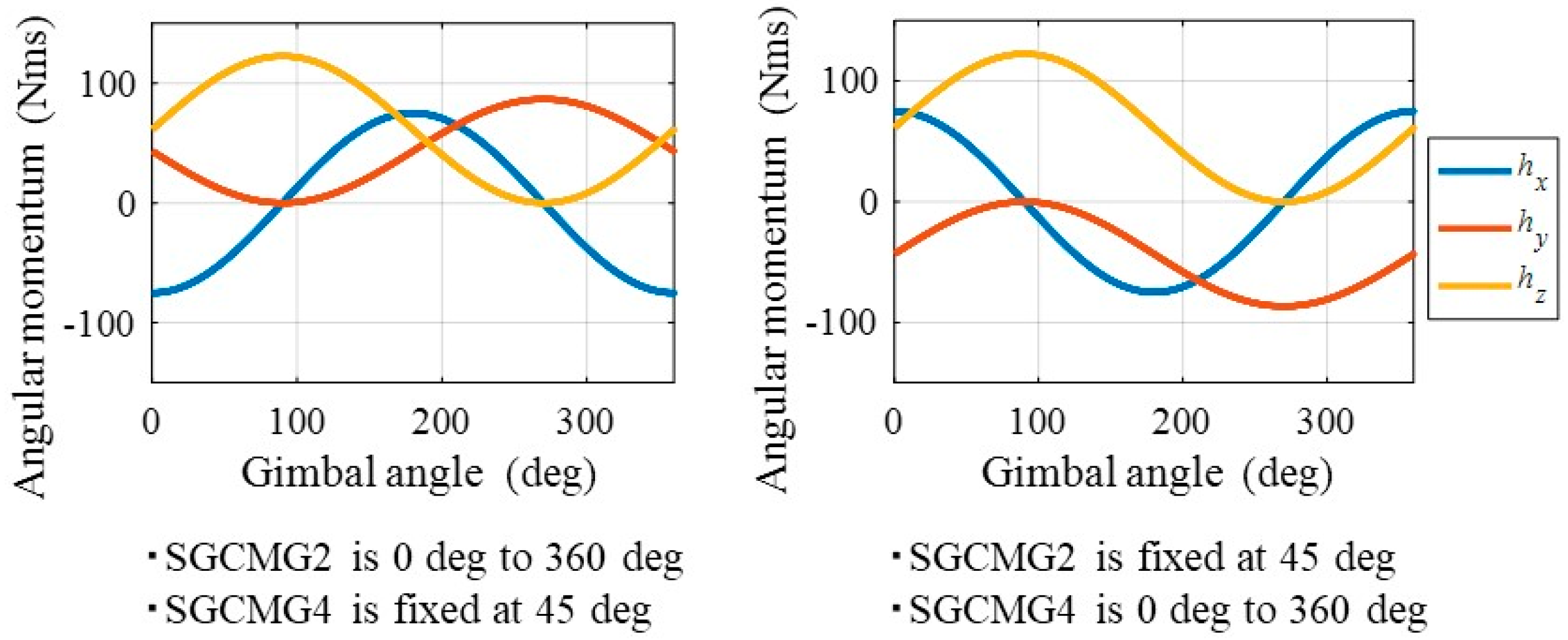
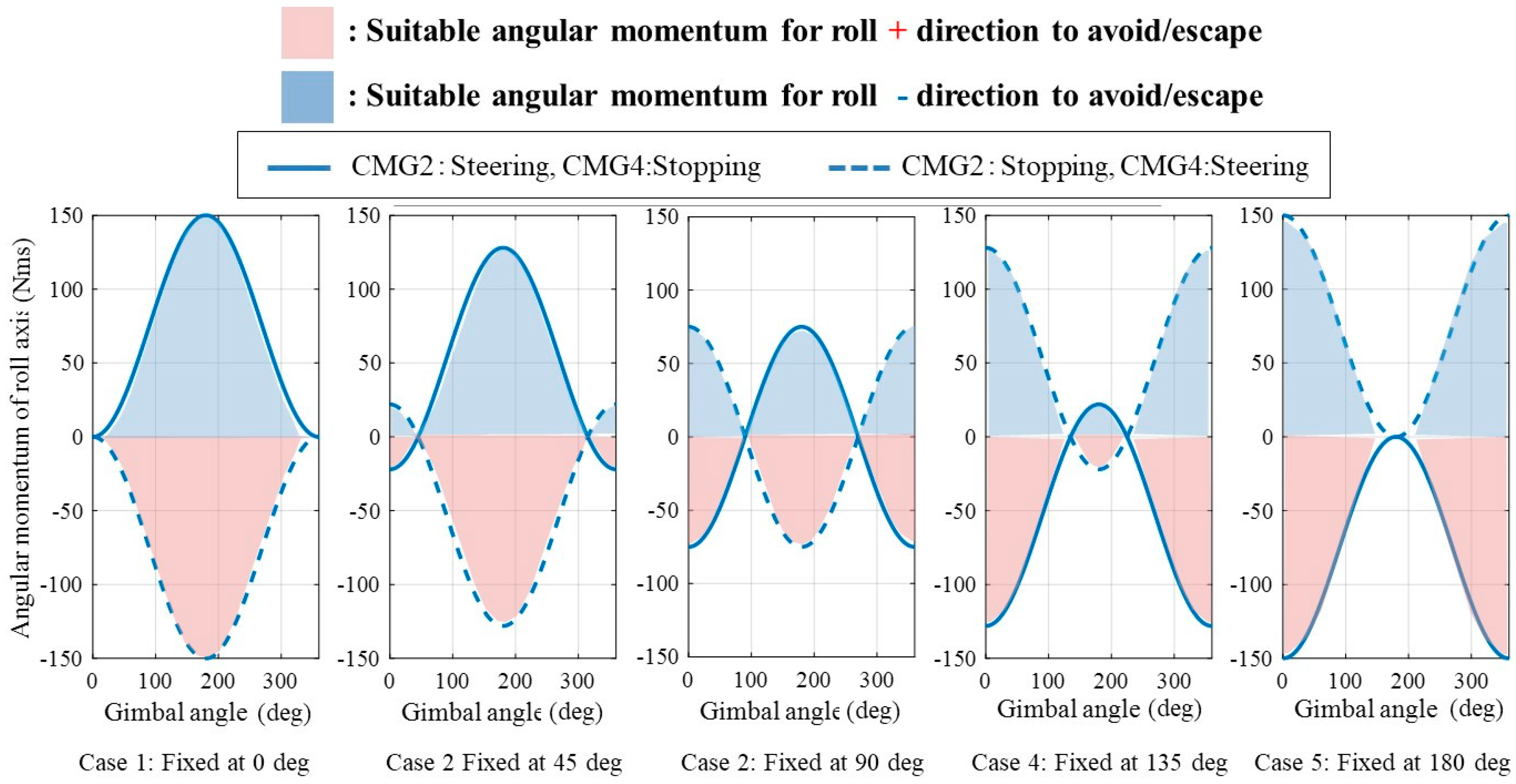
Next, for formulation of the BSDW, a relationship between the angular momentum that can be held by asymmetrically steering SGCMG 2 and SGCMG 4 is shown in Figure 6. From Figure 6, it can be seen that through the asymmetric steering of SGCMGs, which does not contribute to the attitude maneuver, angular momentum can be held on the attitude maneuver axis. In the positive direction of the roll axis maneuver, the angular momentum of SGCMGs is negative, and in the negative direction of the roll axis maneuver, the angular momentum of SGCMGs is positive. This is because the SDRE control system using SISM calculates the optimal control input that maximizes the resource of the output torque. Therefore, by designing the BSDW in consideration of the relationship between the direction of the attitude maneuver and the gimbal angles of SGCMG 2 and SGCMG 4, singularity avoidance/escape steering suitable for agile attitude maneuvers becomes possible. Figure 7 shows a brief summary of this relationship. Although not shown in this paper, in the case of the yaw axis and multiple axis maneuvers there is no symmetry in steering, but BSDW with SISM can also avoid/escape the singularity. This is because the BSDW can control the output of the singularity avoidance/escaping steering suitable for each attitude maneuver axis as shown in Figure 6.
Finally, we show a selection method of BSDW satisfying the above relationship:
where and are gimbal angle of SGCMG2 and SGCMG4 when . It is assumed that the magnitude and sign of the gimbal angle are normalized from 0 to 360 degrees using the periodicity of trigonometric function.
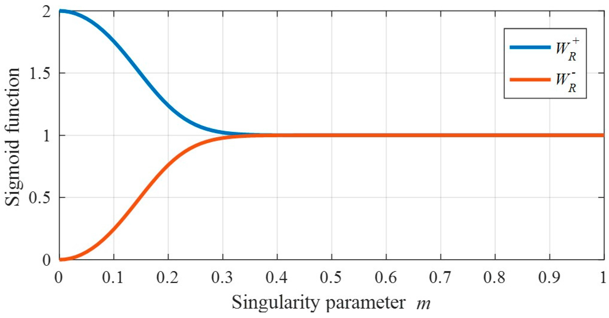
The weighting functions and , as shown in Equations (28) and (29), are designed by a sigmoid function where the difference between and becomes significantly larger when . When the difference between the weighting functions is large, the control input is calculated such that the other steering amount increases so that one of the steering amounts of SGCMG 2 and SGCMG 4 is decreased. Thus, and make it possible to realize the concept of singularity avoidance/escape suitable for the direction of the attitude maneuver axis described above.
where is a very small positive scalar for , is a positive scalar of basic weighting function, and is a positive scalar to determine a sensitivity of and . In this paper, we determine and . Therefore, and are shown in Figure 8.
2.3.3. Design of State-Dependent Weighting (SDW) Matrix of State
First, the SDW matrix of state is expressed as
where is a SDW of quaternion error , is a SDW of satellite angular velocity error , is a SDW of gimbal angle error, and is a SDW of gimbal angular velocity error. By setting as large, agility increases, and by setting as large, the convergence to a target attitude angle increases. Although one study [21] shows that it is possible to achieve both agility and convergence by making the SDW of state state-dependent, in this paper, we use constant values for simplicity.
Finally, the SDW matrix of state is expressed as
3. Results and Discussion
3.1. Conditions for Numerical Simulation of Comparison with the Conventional Method
A large-angle rest-to-rest maneuver simulation verifies the control performance of the proposed control system consisting of SISM and BSDW. Additionally, by comparing the proposed control system with the conventional steering law [10], we verify the usefulness of the proposed method from the viewpoint of the agility of attitude maneuvering and the performance of singularity avoidance/escape and gimbal angle guidance. The conventional steering law can also provide singularity avoidance/escape and gimbal angle guidance by torque producing and null motion. In addition, an SDRE is adopted as the attitude controller to Equation (19), and all design variables of the conventional method are selected so as to maneuver in the shortest time.
The settling condition of the satellite attitude is set to degrees, and the parameters are listed in Table 2.
3.2. Results of Numerical Simulation of Comparison with the Conventional Method
Figure 9 and Figure 11 show the results of the conventional method, and Figure 10 and Figure 12 show the results of the proposed method. Moreover, results of attitude settling time and terminal gimbal angle are shown in Table 3.
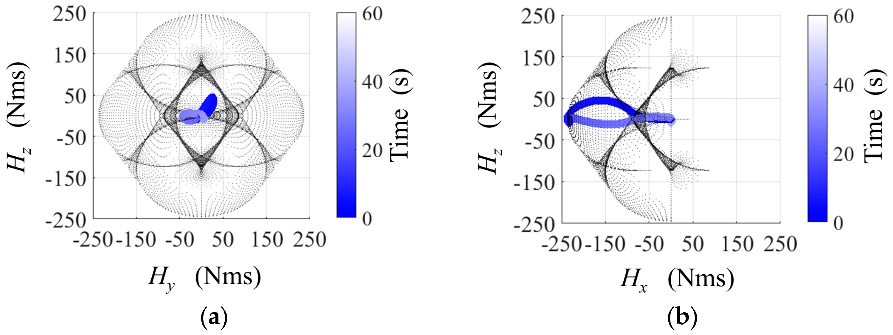
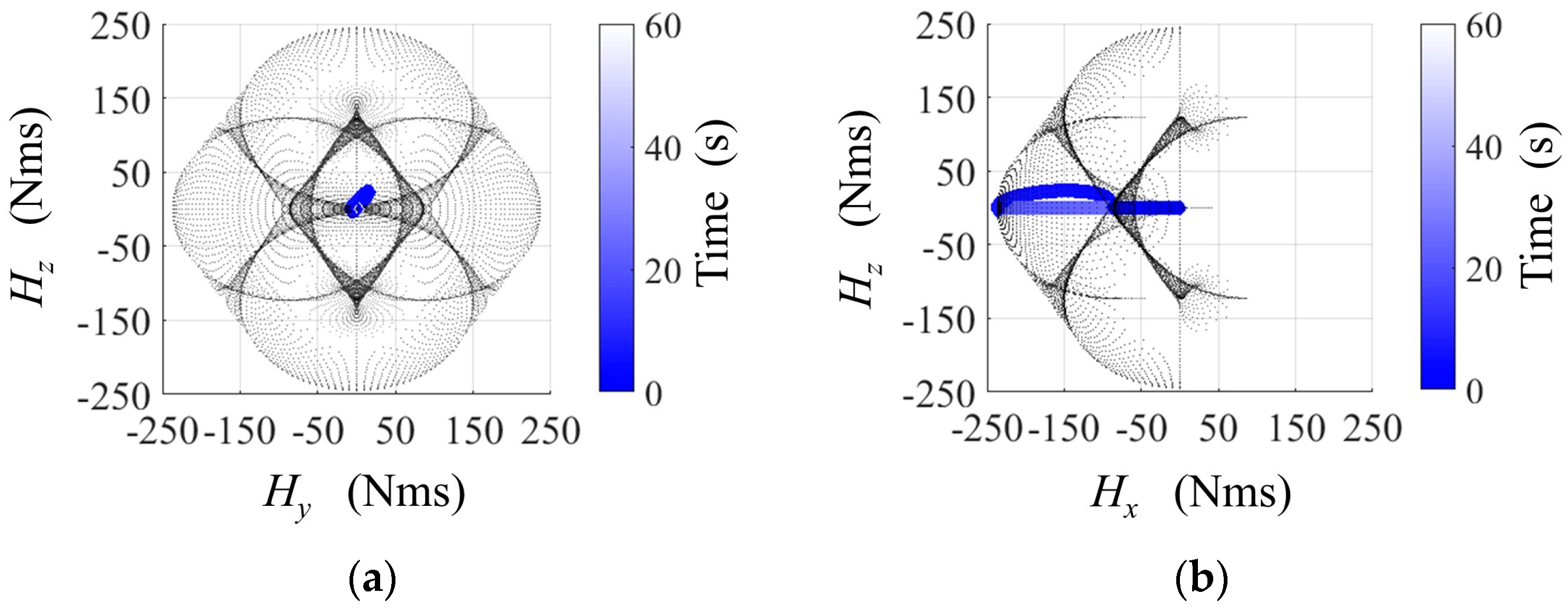
First, it can be seen from Figure 9 and Figure 10 that the both conventional and proposed method can avoid an internal singularity. After the avoidance, it is confirmed that it reaches the external singularity which is the performance limit. However, in the conventional method, the amount of movement in the angular momentum space is larger than in the proposed method. This is an undesirable behavior because the possibility of falling into another singularity after the singularity avoidance/escape becomes high.
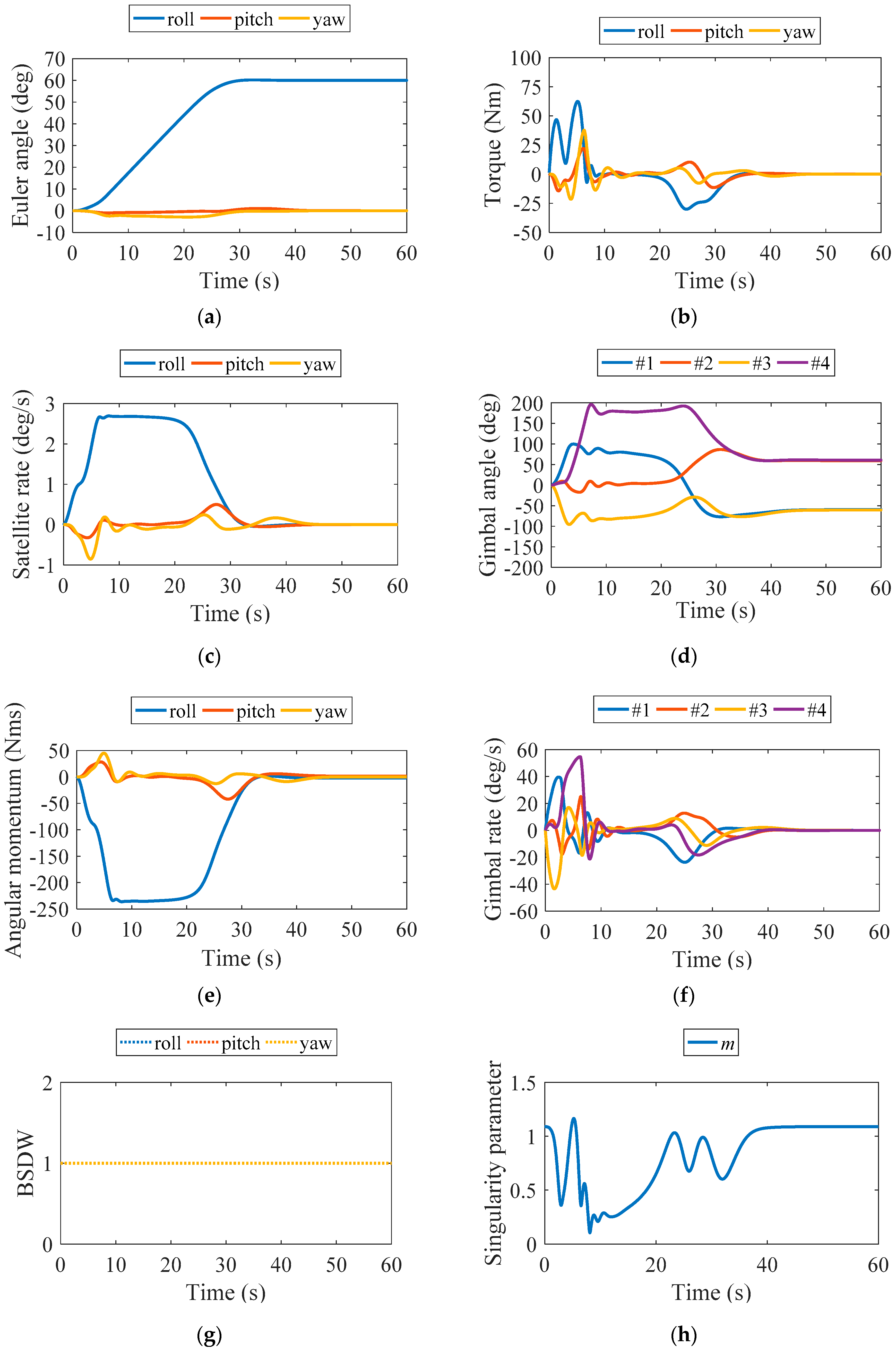
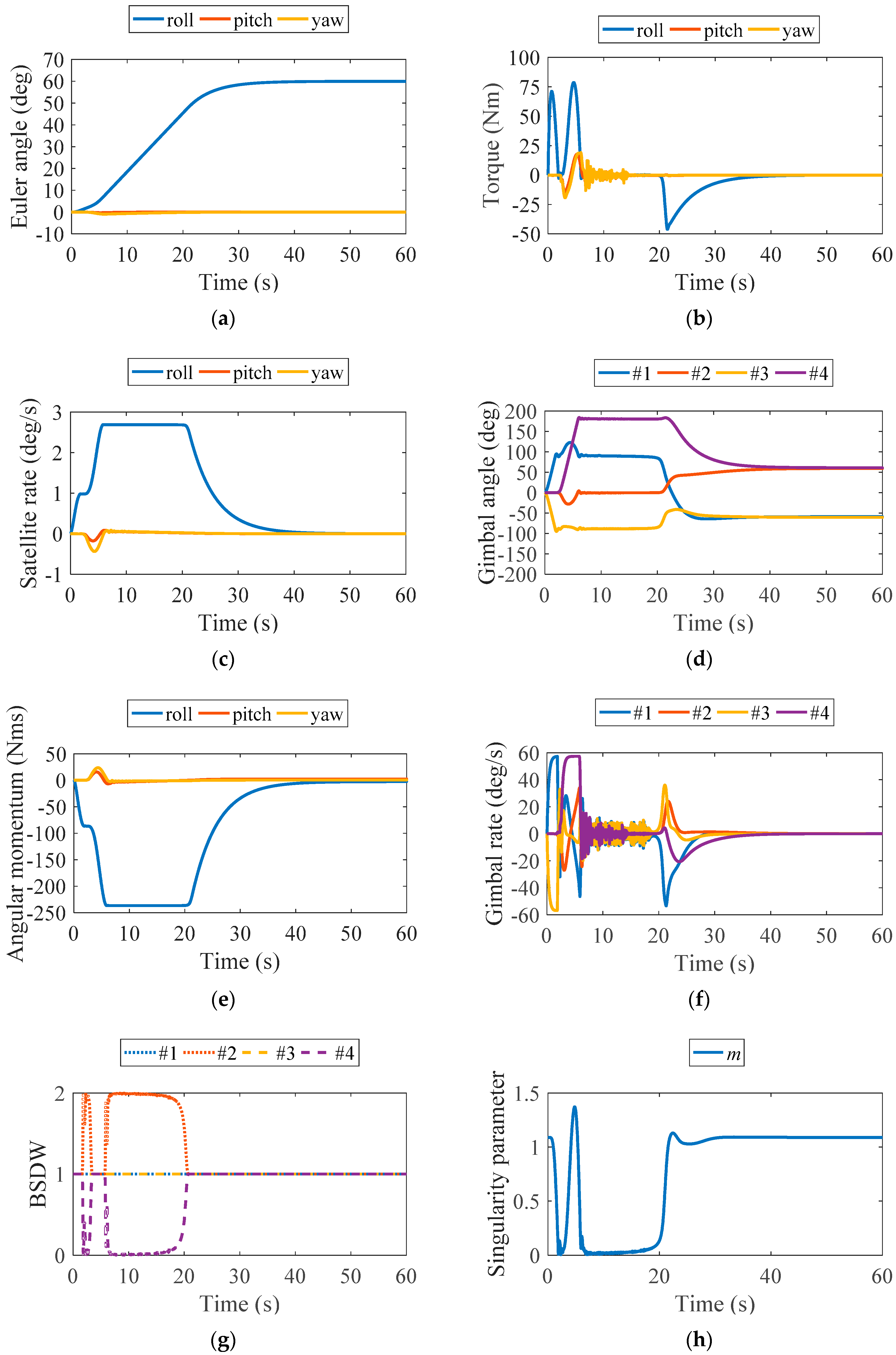
Next, as shown in Figure 11e and Figure 12e, the proposed method has a longer time to hold the maximum angular momentum that SGCMGs can have. As a result, since it is possible to lengthen the attitude maneuver time at the maximum angular velocity, this is advantageous for an agile attitude maneuver. Furthermore, from Figure 11c and Figure 12c, the time to reach the maximum satellite angular velocity is about 1.5 s faster in the proposed method. This is because gimbal steering for singularity avoidance/escape suitable for the direction of the attitude maneuver axis by the BSDW (in Figure 12g) is performed near the singularity. From the above, it is possible to shorten the attitude maneuver time of the proposed method by 3.8 s with respect to the comparison method, as shown in Table 3. Therefore, it was shown that the proposed method is more suitable for agile maneuvering.
As shown in Figure 11b, torque is outputted to the roll axis and the other axis. Therefore, since it is not taken into account in the attitude controller, there is a possibility that the stability might be adversely affected. On the other hand, as shown in Figure 12b the proposed method also outputs the torque to the other axes, but because it is realized by optimal input from the attitude controller, there is no adverse effect on the stability.
Moreover, as shown in Table 3, the gimbal angle guidance of both methods is performed well. This is because an optimal distribution of gimbal steering for the attitude maneuver and gimbal angle guidance is performed in both methods. From the above, it is shown that the proposed method is effective for agile attitude maneuvers in comparison with the conventional method.
3.3. Conditions for Numerical Simulation with Respect to an Uncertainty of the Plant
In this section, we verify the robustness against the moment of inertia which is likely to contain an error in model identification on the ground. However, a general robustness analysis of SDRE has not been determined. Therefore, as an initial study, the true values used for updating the state quantity of the real plant are set in four patterns with respect to the identification value. Since the SDLR of the proposed method depends on the state and the control gain of SDRE also changes depending on the state, it is possible to verify the robustness to uncertainty including the time-variant case by this simplified simulation.
The true value of the moment of inertia is shown in the Table 4, where the error of the true value with respect to the identification value is assumed as 20% of the identification value kgm2. As the value used in the SDRE controller, the value of identification kgm2 is used for all of cases (a) to (e). Therefore, a control input calculated with the identification value different from the actual moment of inertia of the plant is input to the plant.
3.4. Results of Numerical Simulation with Respect to an Uncertainty of the Plant
Table 5 shows attitude settling time and terminal gimbal angle error in cases (a) to (e).
In cases (b) and (c), the settling times are slower than in case (a), because it is difficult to maneuver with respect to roll axis. On the other hand, since the cases (d) and (e) are easy to maneuver with respect to the roll axis, the settling time is faster than in case (a). However, since the attitude has settled in every case, it is considered that the robustness of proposed method against the moment of inertia is high. This robustness can also be confirmed from the fact that the performance of gimbal angle guidance shows almost the same performance as case (a) in all cases.
4. Conclusions
In this study, we integrated a satellite and SGCMGs and designed a model with the gimbal angular velocity as input. We showed the proposed SISM and BSDW can generate optimal gimbal angular velocity input without solving inverse kinematics. As the target gimbal angle can be explicitly designed by the proposed control system, it can guide the initial gimbal angle, which is advantageous for the next mission. Numerical simulation showed that the singularity avoidance performance up to the target gimbal angle, and the guidance performance of the gimbal angle, are improved with respect to the conventional method owing to the optimality of the gimbal angular velocity input. Moreover, we showed that it is possible to perform agile attitude maneuvers considering the next mission.
Although this paper assumes that the satellite is a rigid body, robustness against external disturbances such as solar array paddles and fuel sloshing should also be evaluated. This is a task to be verified in the future. However, we demonstrated that the vibration of solar array paddles, which is not considered in the SDRE controller, can be stabilized by the state-dependent weight matrix as shown in [21]. Therefore, even with the proposed method, it can be stabilized in the same way, and it is considered that it also has the robustness against the above disturbances.
Acknowledgments
This work was supported by education and research fund from Keio University.
Author Contributions
Ryotaro Ozawa and Masaki Takahashi conceived and designed the proposed method and verification simulations; Ryotaro Ozawa performed the numerical simulations; Ryotaro Ozawa wrote the paper.
Conflicts of Interest
The authors declare no conflict of interest.
Nomenclature
| Wheel speed of the SGCMG | |
| Gimbal axis vector of the SGCMG | |
| i-th gimbal axis vector of the SGCMG (i = 1, 2, 3, 4) | |
| Skew angle of four SGCMGs | |
| i-th gimbal angle of the SGCMG (i = 1, 2, 3, 4) | |
| Reference of the state vector | |
| State vector | |
| Reference of the torque vector | |
| Torque vector produced by the angular momentum exchange | |
| Control torque input vector by the controller | |
| Gimbal angular acceleration vector | |
| Reference of the gimbal angular velocity vector | |
| Gimbal angular velocity vector | |
| Control gimbal angle input vector by the controller | |
| Gimbal angle vector | |
| Gimbal angular acceleration error vector | |
| Gimbal angular velocity error vector | |
| Gimbal angle error vector | |
| Target gimbal angle vector | |
| Jacobian matrix of SGCMGs depending on | |
| Jacobian matrix of SGCMGs depending on | |
| Singularity parameter | |
| Quaternion vector of the satellite attitude | |
| Quaternion error vector of the satellite attitude | |
| Time derivative of | |
| Time derivative of | |
| Target angular velocity vector of the satellite | |
| Angular velocity vector of the satellite | |
| Angular velocity error vector of the satellite | |
| Time derivative of | |
| Time derivative of | |
| Moment of inertia matrix of the satellite | |
| Target angular momentum vector of the SGCMG | |
| Angular momentum vector of the SGCMG | |
| Angular momentum error vector of the SGCMG | |
| Angular momentum matrix of the SGCMG wheel | |
| Nonlinear function depending on | |
| Equilibrium point of the system | |
| Control input vector | |
| Infinite-time performance criterion | |
| State-Dependent Weighting matrices | |
| Optimal index | |
| Solution matrix of SDRE | |
| State-Dependent Coefficient (SDC) matrices | |
| Error matrix of | |
| Unit matrix | |
| Coupling matrix between and | |
| Coupling matrix between and | |
| Time constant of gimbal motor | |
| Very small negative scalar | |
| Design parameters of and | |
| Weighting functions of the proposed method | |
| Gimbal angle of SGCMG2 and SGCMG4 when |
References
- Giorgi, G.; Teunissen, P.J.G.; Verhagen, S.; Buist, P.L. Testing a new multivariate GNSS carrier phase attitude determination method for remote sensing platforms. Adv. Space Res. 2010, 46, 118–129. [Google Scholar] [CrossRef]
- Hauschild, A.; Grillmayer, G. GPS Based Attitude Determination for the Flying Laptop Satellite. In Proceedings of the 6th IAA Symposium on Small Satellites for Earth Observation (IAA-B6-0601), Berlin, Germany, 23–26 April 2007. [Google Scholar]
- Cornick, D.E. Singularity Avoidance Control laws for single gimbal control moment gyros. In Proceedings of the AIAA Guidance and Control Conference, Denver, CO, USA, 6–8 August 1979; pp. 20–33. [Google Scholar]
- Bedrossian, N.S.; Paradiso, J.; Bergmann, E.V.; Rowell, D. Steering law design for redundant single-gimbal control moment gyroscopes. J. Guid. Control Dyn. 1990, 13, 1083–1089. [Google Scholar] [CrossRef]
- Ford, K.A.; Hall, C.D. Singular direction avoidance steering for control-moment gyros. J. Guid. Control Dyn. 2000, 23, 648–656. [Google Scholar] [CrossRef]
- Wie, B.; Bailey, D.; Heiberg, C.J. Singularity robust steering logic for redundant single-gimbal control moment gyros. J. Guid. Control Dyn. 2001, 24, 865–872. [Google Scholar] [CrossRef]
- Wie, B. Singularity escape/avoidance steering logic for control moment gyro systems. J. Guid. Control Dyn. 2005, 28, 948–956. [Google Scholar] [CrossRef]
- Yu, L.H.; Liu, S.L.; Wang, X.Y.; Huang, L. CMGs-based steering law design for high attitude stability and quick attitude maneuver agile satellite. In Proceedings of the 14th International Conference on Space Operations (AIAA 2016-2553), Daejeon, Korea, 16–20 May 2016. [Google Scholar]
- Leve, F.A.; Fitz-Coy, N.G. Hybrid steering logic for single-gimbal control moment gyroscopes. J. Guid. Control Dyn. 2010, 33, 1202–1212. [Google Scholar] [CrossRef]
- Kanzawa, T.; Haruki, M.; Yamanaka, K. Agile multitarget attitude maneuvers using both torque-producing motion and null motion for gimbal angle control of control moment gyros. In Proceedings of the 57th Space Science and Technology Association Conference (JSASS-2013-4369), Tottori, Japan, 9–11 October 2013. [Google Scholar]
- Kusuda, Y.; Takahashi, M. Design of feedback control system using nominal inputs for satellite attitude maneuver using control moment gyros. In Proceedings of the AIAA Guidance, Navigation, and Control Conference and Exhibit (AIAA 2009-6205), Chicago, IL, USA, 10–13 August 2009. [Google Scholar]
- Sato, S.; Takahashi, M. Singularity escape of satellite with control moment gyros using path planning of angular momentum. Trans. Jpn. Soc. Mech. Eng. 2013, 79, 303–314. [Google Scholar] [CrossRef]
- Zhang, W.; Zhang, Y.; Li, W.; Wang, Y. Path planning for rapid large-angle maneuver of satellites based on the gauss pseudospectral method. Math. Probl. Eng. 2016, 2016, 1–7. [Google Scholar] [CrossRef]
- Tikhonov, A.N. Solution of incorrectly formulated problems and the regularization method. Sov. Math. Dokl. 1963, 4, 1035–1038. [Google Scholar]
- Neumaier, A. Solving ill-conditioned and singular linear systems: A tutorial on regularization. SIAM J. Appl. Math. 1998, 40, 636–666. [Google Scholar] [CrossRef]
- Voronin, S.; Martinsson, P.G. Efficient algorithms for cur and interpolative matrix decompositions. Adv. Comput. Math. 2017, 43, 495–516. [Google Scholar] [CrossRef]
- Mracek, C.P.; Cloutier, J.R. Control designs for the nonlinear benchmark problem via the state-dependent Riccati equation method. Int. J. Robust Nonlinear 1998, 8, 401–433. [Google Scholar] [CrossRef]
- Çimen, T. Survey of state-dependent Riccati equation in nonlinear optimal feedback control synthesis. J. Guid. Control Dyn. 2012, 35, 1025–1047. [Google Scholar] [CrossRef]
- Ozawa, R.; Takahashi, M. Agile attitude maneuver via SDRE controller using CMG integrated satellite model. In Proceedings of the 61th Space Science and Technology Association Conference (JSASS-2017-4420), Niigata, Japan, 25–27 October 2017. [Google Scholar]
- Stansbery, D.T.; Cloutier, J.R. Position and attitude control of a spacecraft using the state-dependent Riccati equation technique. In Proceedings of the American Control Conference, Chicago, IL, USA, 28–30 June 2000; pp. 1867–1871. [Google Scholar]
- Ozawa, R.; Takahashi, M. Vibration control of flexible satellite using the command shaping considering singularity of control moment gyro. In Proceedings of the 60th Space Science and Technology Association Conference (JSASS-2016-4315), Hokkaido, Japan, 6–9 September 2016. [Google Scholar]
Figure 1.
The scheme of a single-gimbal control moment gyro (SGCMG) (a) and four-skew array single-gimbal control moment gyros (SGCMGs) (b).
Figure 1.
The scheme of a single-gimbal control moment gyro (SGCMG) (a) and four-skew array single-gimbal control moment gyros (SGCMGs) (b).

Figure 2.
Block diagram of conventional method and proposed method.

Figure 3.
Relationship between the output torque and singularity of SGCMGs.

Figure 4.
A singular surface (a singularity in the dimension of angular momentum) when (a), (b), and (c).
Figure 4.
A singular surface (a singularity in the dimension of angular momentum) when (a), (b), and (c).

Figure 5.
Overview of state-dependent Riccati equation (SDRE) method.

Figure 6.
Relationship between angular momentum of SGCMGs and the gimbal angle.

Figure 7.
Overview of suitable angular momentum of SGCMGs for singularity avoidance/escape considering the direction of the roll axis maneuver.
Figure 7.
Overview of suitable angular momentum of SGCMGs for singularity avoidance/escape considering the direction of the roll axis maneuver.

Figure 8.
Sigmoid function dependent on the singularity parameter.

Figure 9.
Results of the trajectory of SGCMG angular momentum (conventional method) with a singular surface: (a) Hy-Hz plane; (b) Hx-Hz plane.
Figure 9.
Results of the trajectory of SGCMG angular momentum (conventional method) with a singular surface: (a) Hy-Hz plane; (b) Hx-Hz plane.

Figure 10.
Results of the trajectory of SGCMG angular momentum (proposed method) with a singular surface: (a) Hy-Hz plane; (b) Hx-Hz plane.
Figure 10.
Results of the trajectory of SGCMG angular momentum (proposed method) with a singular surface: (a) Hy-Hz plane; (b) Hx-Hz plane.

Figure 11.
Results of the conventional method as: (a) Time history of the Euler angle; (b) Time history of torque by SGCMGs; (c) Time history of the satellite angular velocity; (d) Time history of the gimbal angle; (e) Time history of the angular momentum of SGCMGs; (f) Time history of the gimbal angular velocity; (g) Time history of biased state-dependent weighting (BSDW); (h) Time history of the singularity parameter.

Figure 12.
Results of the proposed method as: (a) Time history of the Euler angle; (b) Time history of the torque by SGCMGs; (c) Time history of the satellite angular velocity; (d) Time history of the gimbal angle; (e) Time history of the angular momentum of SGCMGs; (f) Time history of the gimbal angular velocity; (g) Time history of the BSDW; (h) Time history of singularity parameter.


Table 1.
Relationship between the maneuver axis and gimbal steering number 1.
| Maneuver Axis | Gimbal Steering Number |
|---|---|
| roll | #1 and #3 |
| pitch | #2 and #4 |
| yaw | all SGCMGs |
| roll and pitch | all SGCMGs |
| pitch and yaw | all SGCMGs |
| yaw and roll | all SGCMGs |
| roll, pitch, and yaw | all SGCMGs |
1 single-gimbal control moment gyros (SGCMGs).
Table 2.
Parameters and values for the numerical simulation.
| Parameters | Symbols | Values |
|---|---|---|
| moment of inertia of satellite | kgm2 | |
| angular momentum of SGCMG | 75 Nms | |
| target angular velocity of satellite | deg/s | |
| initial gimbal angle | - | deg |
| target gimbal angle | deg | |
| initial satellite euler angle | - | deg |
| target satellite euler angle | - | deg |
| target gimbal angular velocity | deg/s | |
| target angular momentum | Nms | |
| very small negative scalar | −10−9 | |
| very small positive scalar | 10−5 | |
| time constant of gimbal motor | 0.3 s | |
| skew angle of four SGCMGs | 54.74 deg | |
| Maximum gimbal angular velocity | - | 1 rad/s |
Table 3.
Results of numerical simulation.
| Evaluation Index | Comparative Method | Proposed Method |
|---|---|---|
| attitude settling time (s) | 56.7 | 52.9 |
| terminal gimbal angle error (degrees) |
Table 4.
Case of moment of inertia used for the real plant when: (a) The identification value and true value match (the above simulation result); (b) All axes are hard to rotate; (c) The roll axis is hard to rotate, and the other axes are easy to rotate; (d) The roll axis is easy to rotate, and the other axes are hard to rotate; and (e) All axes are easy to rotate.
| Cases | True Values of the Real Plant (kgm2) |
|---|---|
| (a) | |
| (b) | |
| (c) | |
| (d) | |
| (e) |
Table 5.
Results of numerical simulation in cases (a) to (e).
| Cases | Attitude Settling Times (s) | Terminal Gimbal Angle Errors (Degrees) |
|---|---|---|
| (a) | 52.9 | |
| (b) | 56.3 | |
| (c) | 56.3 | |
| (d) | 49.7 | |
| (e) | 49.7 |
© 2018 by the authors. Licensee MDPI, Basel, Switzerland. This article is an open access article distributed under the terms and conditions of the Creative Commons Attribution (CC BY) license (http://creativecommons.org/licenses/by/4.0/).
Share and Cite
MDPI and ACS Style
Ozawa, R.; Takahashi, M. Agile Attitude Control and Singularity Avoidance/Escape by the SDRE Method Using a Biased State-Dependent Weighting Matrix. Appl. Sci. 2018, 8, 140. https://doi.org/10.3390/app8010140
AMA Style
Ozawa R, Takahashi M. Agile Attitude Control and Singularity Avoidance/Escape by the SDRE Method Using a Biased State-Dependent Weighting Matrix. Applied Sciences. 2018; 8(1):140. https://doi.org/10.3390/app8010140
Chicago/Turabian StyleOzawa, Ryotaro, and Masaki Takahashi. 2018. "Agile Attitude Control and Singularity Avoidance/Escape by the SDRE Method Using a Biased State-Dependent Weighting Matrix" Applied Sciences 8, no. 1: 140. https://doi.org/10.3390/app8010140
Note that from the first issue of 2016, this journal uses article numbers instead of page numbers. See further details here.