Metallic, 3D-Printed, K-Band-Stepped, Double-Ridged Square Horn Antennas

1
Department of Electrical and Computer Engineering, Faculty of Engineering, National University of Singapore, Singapore 117576, Singapore
2
College of Electronics and Information Engineering, Sichuan University, Chengdu 610065, China
3
School of Electronic and Information Engineering, Nanjing University of Information Science and Technology, Nanjing 210044, China
4
School of Physics and Optoelectronic Engineering, Guangdong University of Technology, Guangzhou 510006, China
*
Author to whom correspondence should be addressed.
Appl. Sci. 2018, 8(1), 33; https://doi.org/10.3390/app8010033
Submission received: 18 October 2017
/
Revised: 30 November 2017
/
Accepted: 20 December 2017
/
Published: 27 December 2017
(This article belongs to the Special Issue 3D Printed Antennas)
Abstract
:Featured Application
This paper introduces the application of metallic 3D printing technology to fabricate K-band-stepped, double-ridged horn antennas. The proposed antennas feature comparable performance with commercial counterparts with lower cost and a reduced turn-around time.
Abstract
This paper presents K-band-stepped, double-ridged square horn antennas fabricated by metallic 3D printing technology in copper (85% copper and 15% stannum) and aluminum alloy (89.5% aluminum, 10% silicon, and 0.5% magnesium). Compared with the popular dielectric 3D-printed horn antenna, the metallic counterpart features better mechanical robustness in terms of material. Moreover, the metallic horns are printed in one piece in one run, different from the dielectric horns that are printed in split pieces and electroplated, they simplify the process and thus result in reduced cost. The agreement between the simulation and measurement results verified the antenna’s performance. Both the 3D-printed copper and aluminum alloy antenna have an impedance bandwidth across the K-band, with a maximum gain of 13.23 dBi @ 25 GHz and 13.5 dBi @ 24 GHz, respectively. The metallic, 3D-printed horn antennas are preferable alternatives to replace traditionally-fabricated antennas.
1. Introduction
The 3D printing technology, invented in 1980s, is catching attention recently because of its eco-friendliness, short turn-around time and versatility with complex structures [1,2,3]. In terms of materials, 3D printing technology can be categorized as dielectric and metallic, both of which feature merits as well as drawbacks. Dielectric 3D printed parts usually bear low material and process costs. The low body mass is the other advantage which is highly appreciated in space engineering due to the tightly controlled payload. However, the weak mechanical robustness and the electrostatic discharge (ESD) from dielectric 3D printed parts are the major concerns under harsh circumstances. For the metallic 3D printed parts, the mechanical weakness and ESD might not be observed, while the heavy body mass and comparatively high material cost are not desirable.
The horn antenna is widely used in microwave engineering. The traditional way to fabricate horn antennas is computer numerical control (CNC) machining [4], electrical discharge machining (EDM), deposition technology and stacked ring technology [5]. CNC is the most popular, especially for fabricating low-frequency horns. EDM and deposition are often used for terahertz (THz) antenna fabrication because of the required tight dimensional tolerance. The stacked ring technology is limited to producing horns with small physical dimensions, due to the ring alignment problem. Recently, 3D printing technology has been attempted for horn antenna fabrication. For example, Timbie reported a dielectric 3D-printed, W-band (75–110 GHz) corrugated horn antenna, which was first printed in split pieces, then metal plated and finally assembled [6]. Chieh proposed a Ku-band (10–16 GHz) corrugated horn antenna by dielectric 3D printing [7], which went through the same process as [6]. Bieren managed to take advantage of this technology to print an H-band dielectric horn antenna [8]. The metallic 3D printing technology was first used for horn antenna fabrication in 2012 by Garcia [9], who printed Ku-band horn antennas using electron beam melting (EBM) turned up with 25.9 um surface roughness by an un-optimized post-process. The working principle of EBM (i.e., the high pre-heat temperature and the pre-sintering of the powder bed) is the main cause of the relatively poor surface finishing compared to laser-based powder processes. Guo and Zhang pushed the upper limit of the metallic 3D printed horn antenna up to the H-band (220–325 GHz) [10,11,12]. They used selective laser melting (SLM) to print a series of millimeter-wave (mmWave) and terahertz (THz) passive devices of comparable performance with commercial ones. Gordon demonstrated a metallic 3D-printed corrugated horn antenna at the F-band (110–140 GHz) for CubeSat application [13]. Ignatenko presented a metallic 3D-printed K-band horn as the feeder for a Luneberg lens [14].
The aforementioned dielectric, 3D-printed, corrugated horn antennas are usually printed in split pieces, then metal plated and assembled, which brings in complexities process-wise. The metallic, 3D-printed corrugated horn antenna was printed in a whole piece in one run [13], however, the surface finishing of roughness Ra = 125 um was far from satisfactory. In this paper, taking advantage of an optimized 3D printing technology, we propose two K-band-stepped, double-ridged horn antennas in aluminum alloy (89.5% aluminum, 10% silicon, and 0.5% magnesium) and copper (85% copper and 15% stannum). This paper is organized as follows. Section 2 explains the design and fabrication of the antennas. Section 3 introduces the characterization of the antennas. Section 4 concludes the paper.
2. Design and Fabrication of the Antennas
The corrugated horn is used either as a single radiator or as the feed for a parabolic reflector for its symmetric pattern, low side lobe level and low cross-polarization. The corrugations are designed to excite high order modes such that the field distribution on the aperture demonstrates a hybrid HE11 mode. To achieve acceptable matching across the whole K-band of the horn, ridges are designed to extend the impedance bandwidth toward the lower side band. From the perspective of electromagnetics, the ridges form a parallel-plate structure that supports the propagation of the transverse electro-magnetic (TEM) mode, which has a zero cut-off frequency. As a result, the impedance bandwidth of the horn is extended downwards. To model the ridges in an equivalent circuit, they function as a shunt capacitor that is generally a low-pass device. Hence, the impedance bandwidth is also extended toward the low frequency.
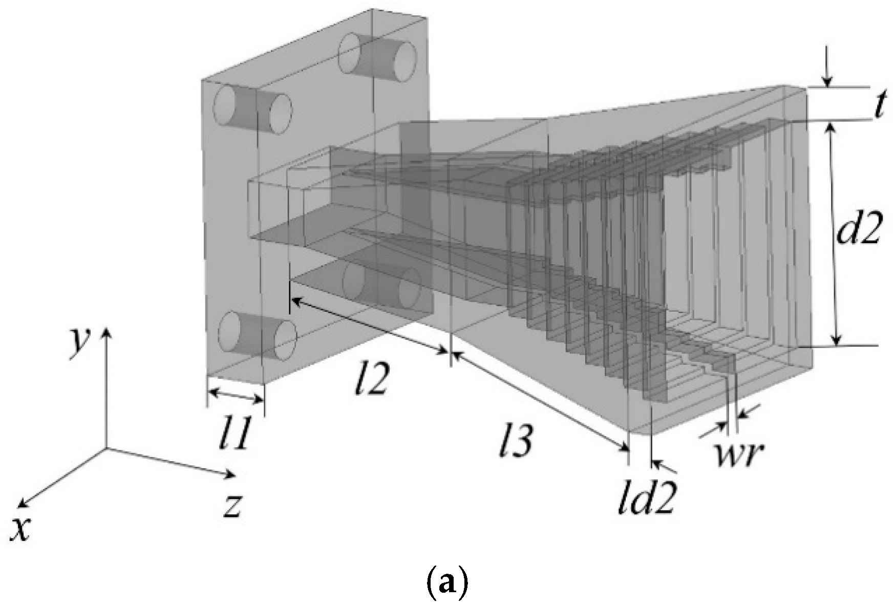
Figure 1 shows the geometries of the K-band, corrugated, ridged, square horn antenna. It is composed of a WR-42 rectangular waveguide (10.7 mm × 4.3 mm) interface, a standard UBR 220 type flange, a rectangular-to-square waveguide taper and the stepped double ridged horn. In Figure 1a, the horn is laid referring to the coordinate origins on the flange. The H-plane of the horn is on x-o-z as in Figure 1b, while the E-plane is on y-o-z in Figure 1c. Since the horn is designed as a linearly polarized horn, as well as for the ease of fabrication, only two ridges were applied on the E-plane to support the propagation of the TEM mode. Table 1 lists the geometries of the horn.
To verify the design, the horn was printed with the selective laser melting (SLM) technology using aluminum alloy and copper, respectively. They were printed along the z-direction in a whole piece in one run, which eliminates the necessity for post electro-plating and assembly compared with the dielectric 3D printed horns. The outer surface of the horns were polished by post processes. The inner surface of the horn, which was indeed the functional surface, was left untouched to maintain the sound structure of the steps and ridges. Outperforming the 125 um surface roughness of the reported powder bed fusion (PBF) technology in [13], the SLM technology used in this paper turned out to be 6 um and 3 um for the aluminum alloy and copper horns respectively on the inner surface. The flange interface is milled for a tight connection with the vector network analyzer (VNA) extender. Figure 2a,b show the horns from the outlook; the post-polishing endows them with a shiny appearance. Figure 2c,d present the horns from the aperture, in which the corrugations and ridges are seen. However, for the unprocessed inner surface, the roughness is much worse than the outer surface. The milled flanges are shown in Figure 2e,f. The roughness on the waveguide opening in both cases gives alternative views on the process tolerance. The roughness on the waveguide interface may give rise to increased reflection, unwanted passive intermodulation (PIM) and conductor loss.
3. Characterization of the Antenna
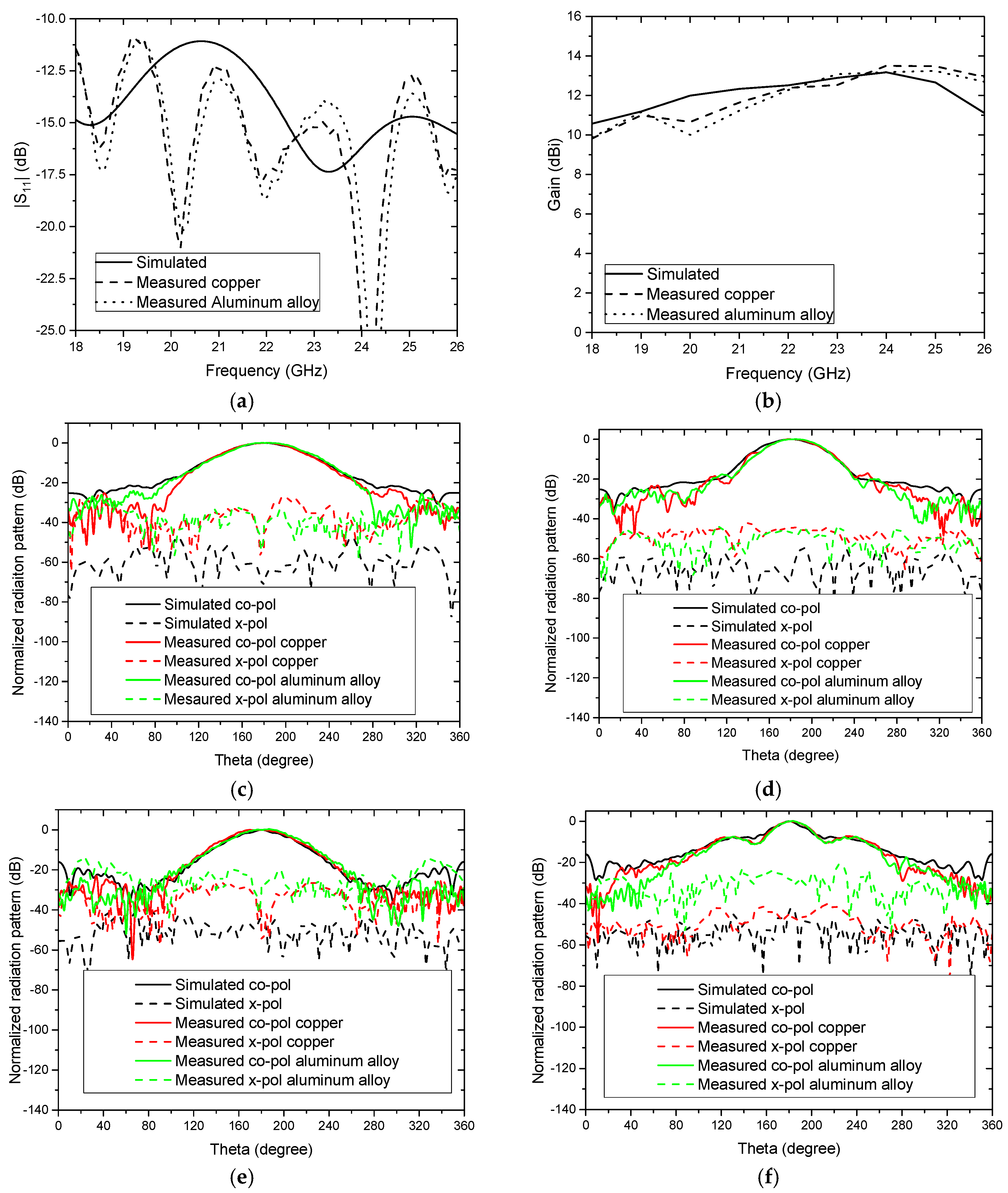
The input impedance of the printed antennas were measured using a Rohde & Schwarz ZVA 50 VNA. The directivity and radiation patterns were measured in a far-field setup in an anechoic chamber. Figure 3a compares the simulated and measured |S11| of the 3D-printed antennas. The impedance bandwidth of the horn covers the whole K-band in simulation for |S11|<−10 dB. In the measurement, both the copper and aluminum alloy horns show an impedance bandwidth from 18 GHz to 26 GHz. Behavioral agreement is observed between simulation and measurement in the |S11|. Figure 3b shows the gain of the horn. The simulated gain is >10 dBi across the K-band with a maximum gain of 13.17 dBi @ 24 GHz. In measurement, the aluminum alloy horn has ~2 dB less in gain than in the simulation, with a maximum gain of 13.23 dBi @ 25 GHz, while the copper horn shows similar behavior as the aluminum alloy horn, with a maximum gain of 13.5 dBi @ 24 GHz. The discrepancies are caused by the conductivity difference and the surface roughness. The antennas are printed by different partners. The different surface roughness is caused by the skills of different technician in post processes. Since the conductivity of the aluminum alloy is lower than that of copper, and the aluminum alloy antenna has a rougher surface finishing than the counterpart, a larger gain decrement is observed in the aluminum horn. Figure 3c–f reveal that both of the aluminum alloy and copper horns have very low side lobe levels in the boresight across the K-band. The measured radiation patterns agree well with the simulation. The increased cross-polarization and deteriorated front-to-back ratio in measurement are caused by diffraction due to the roughness on the inner surface and on the aperture of the horn.
4. Conclusions
We demonstrated the design and fabrication of metallic, 3D-printed, K-band-stepped, double-ridged square horn antennas in this paper. The antenna was printed by SLM technology using aluminum alloy and copper. Compared with the popular dielectric, 3D-printed corrugated horns, the metallic counterparts have process simplicity. The measured and simulated antenna performance agreed well. Future work lies in the integration of the antenna with other microwave passive devices into a radio frontend.
Acknowledgments
This work was supported in part by the National Research Foundation National Additive Manufacturing Innovation Cluster under grant ‘3D printed 60 GHz horn antennas and arrays for next-generation 5G applications’ of Singapore, in part by National Natural Science Foundation of China under the Grant No. 61401296, in part by the National Natural Science Foundation of China under grant 61701326 ‘Research on millimeter-wave multi-functional complex structure waveguide devices based on metallic 3D printing technology‘, and in part by ‘the Fundamental Research Funds for the Central Universities’ of China. The authors thank Kang Ding, Yujian Li, Rongqiang Li, Yingran He for the valuable discussions.
Author Contributions
Bing Zhang is responsible for the antenna design, data processing and manuscript preparation. Yong-Xin Guo is responsible for the manuscript preparation. Hucheng Sun is responsible for antenna measurement. Yanjie Wu is responsible for antenna design.
Conflicts of Interest
The authors declare no conflict of interest.
References
- Hull, C. Apparatus for Production of Three-Dimensional Objects by Stereolithography. U.S. Patent 4575330, 11 March 1986. [Google Scholar]
- Deckard, C.; Beaman, J.; Darrah, J. Selective Laser Sintering with Layerwise Cross-Scanning. U.S. Patent 5155324, 13 October 1992. [Google Scholar]
- Crump, S. Apparatus and Method for Creating Three-Dimensional Objects. U.S. Patent 5121329, 9 June 1992. [Google Scholar]
- Gonzales, A.; Kaneko, K.; Kojima, T.; Asayama, S.; Uzawa, Y. Terahertz corrugated horns (1.25–1.57 THz): Design, Gaussian modeling, and measurements. IEEE Trans. Terahertz Sci. Technol. 2016, 7, 42–52. [Google Scholar]
- Tajima, T.; Song, H.J.; Ajito, K.; Yaita, M.; Kukutsu, N. 300-GHz step-profiled corrugated horn antennas integrated in LTCC. IEEE Trans. Antennas Propag. 2014, 62, 5437–5444. [Google Scholar] [CrossRef]
- Timbie, P.; Grade, J.; van der Veide, D.; Maffei, B.; Pisano, G. Stereolithographed MM-wave corrugated horn antennas. In Proceedings of the 36th International Conference on Infrared, Millimeter and Terahertz Waves (IRMMW-THz), Houston, TX, USA, 2–7 October 2011; pp. 1–3. [Google Scholar]
- Chieh, J.C.; Dick, B.; Loui, S.; Rockway, J.D. Development of a Ku-band corrugated conical horn using 3-D print technology. IEEE Antennas Wirel. Propag. Lett. 2014, 13, 201–204. [Google Scholar] [CrossRef]
- Von Bieren, A.; De Rijk, E.; Ansermet, J.P.; Macor, A. Monolithic metal-coated plastic components for MM-wave applications. In Proceedings of the 39th International Conference on Infrared, Millimeter, and Terahertz Waves (IRMMW-THz), Tucson, TX, USA, 14–19 September 2014; pp. 1–2. [Google Scholar]
- Garcia, C.R.; Rumpf, R.C.; Tsang, H.H.; Barton, J.H. Effects of extreme surface roughness on 3D printed horn antenna. Electron. Lett. 2013, 49, 734–736. [Google Scholar] [CrossRef]
- Zhang, B.; Linnér, P.; Karnfelt, C.; Tam, P.L.; Södervall, U.; Zirath, H. Attempt of the metallic 3D printing technology for millimeter-wave antenna implementations. In Proceedings of the Asia-Pacific Microwave Conference (APMC), Nanjing, China, 6–9 December 2015; pp. 1–3. [Google Scholar]
- Zhang, B.; Zhan, Z.; Cao, Y.; Gulan, H.; Linnér, P.; Sun, J.; Zwick, T.; Zirath, H. Metallic 3D printed antennas for millimeter- and submillimeter-wave applications. IEEE Trans. Terahertz Sci. Technol. 2016, 6, 592–600. [Google Scholar] [CrossRef]
- Zhang, B.; Guo, Y.X.; Zirath, H.; Zhang, Y.P. Investigation on 3-D-printing technologies for millimeterwave and Terahertz applications. Proc. IEEE 2017, 105, 723–736. [Google Scholar] [CrossRef]
- Gordon, A.J.; Novotny, D.R.; Francis, M.H.; Wittmann, R.C.; Butler, M.L.; Curtin, A.E.; Guerrieri, J.R.; Periasamy, L.; Gasiewski, A.J. An all metal, 3-D-printed CubeSat feed horn: An assessment of performance conducted at 118.7503 GHz using a robotic antenna range. IEEE Antennas Propag. Mag. 2017, 59, 96–102. [Google Scholar] [CrossRef]
- Ignatenko, M.; Simakauskas, B.; Notaros, M.; Filipovic, D.S. A phase center-stabilized K/Ka/V band linearly-polarized horn for Luneberg lenses. IEEE Antennas Wirel. Propag. Lett. 2017, 16, 2726–2729. [Google Scholar] [CrossRef]
Figure 1.
Geometries of the 3D-printed, K-band-stepped, double-ridged square horn antenna: (a) three dimensional view; (b) E-plane view; (c) H-plane view.
Figure 1.
Geometries of the 3D-printed, K-band-stepped, double-ridged square horn antenna: (a) three dimensional view; (b) E-plane view; (c) H-plane view.

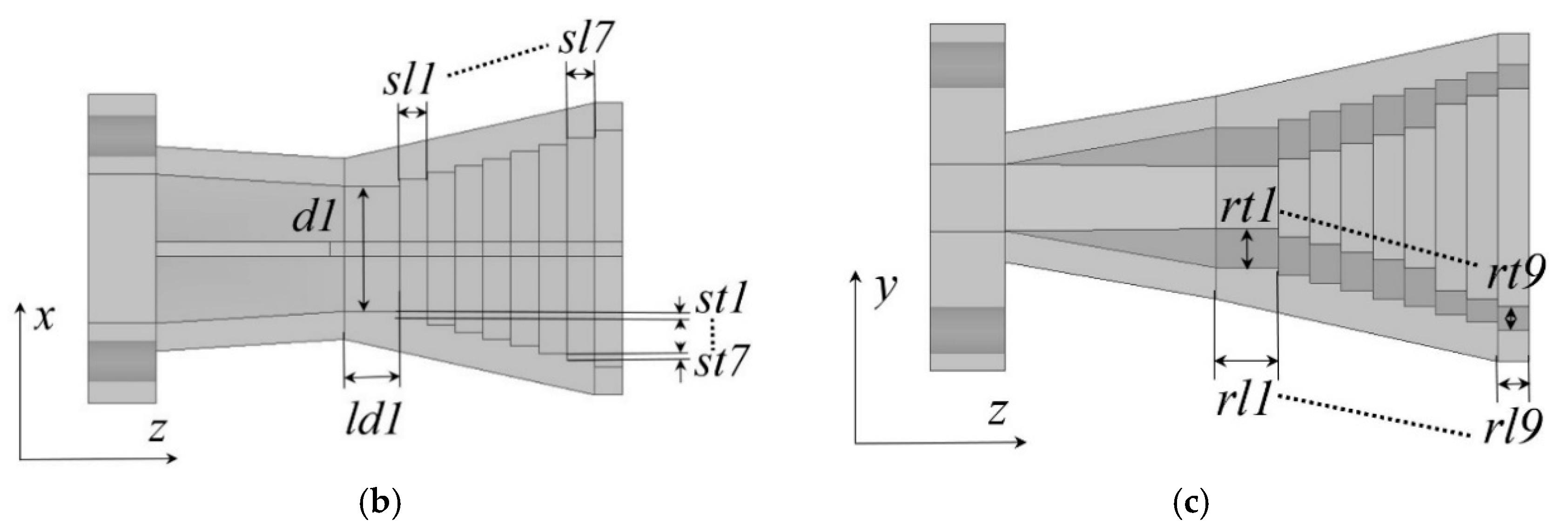
Figure 2.
Photographs of the 3D-printed, K-band-stepped, double-ridged square horns. The aluminium alloy horn: (a) outlook; (c) aperture view; (e) flange view. The copper horn: (b) outlook; (d) aperture view; (f) flange view.
Figure 2.
Photographs of the 3D-printed, K-band-stepped, double-ridged square horns. The aluminium alloy horn: (a) outlook; (c) aperture view; (e) flange view. The copper horn: (b) outlook; (d) aperture view; (f) flange view.
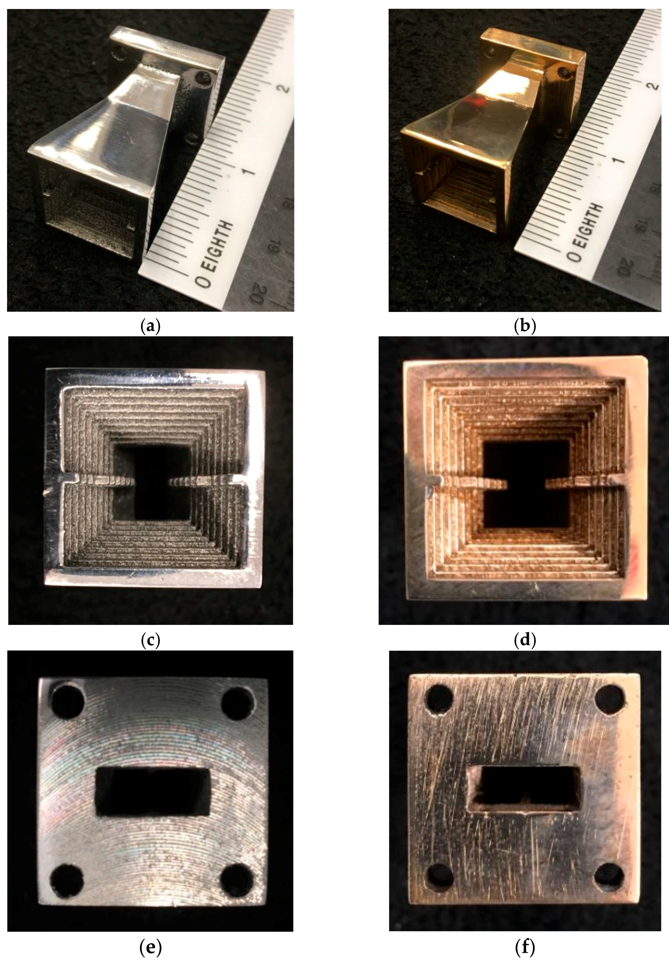
Figure 3.
Measured performance of the 3D-printed, K-band-stepped, double-ridged square horns: (a) |S11|; (b) gain; (c) radiation patterns on phi = 0° @ 18 GHz; (d) radiation patterns on phi = 90° @ 18 GHz; (e) radiaiton patterns on phi = 0° @ 26 GHz; (f) radiation patterns on phi = 90° @ 26 GHz.
Figure 3.
Measured performance of the 3D-printed, K-band-stepped, double-ridged square horns: (a) |S11|; (b) gain; (c) radiation patterns on phi = 0° @ 18 GHz; (d) radiation patterns on phi = 90° @ 18 GHz; (e) radiaiton patterns on phi = 0° @ 26 GHz; (f) radiation patterns on phi = 90° @ 26 GHz.

Table 1.
Geometries of the horn.
| Parameters | (mm) | Parameters | (mm) | Parameters | (mm) | Parameters | (mm) |
|---|---|---|---|---|---|---|---|
| d1 | 9 | d2 | 17 | l1 | 4.83 | l2 | 13.73 |
| l3 | 18.87 | ld1 | 4 | ld2 | 2 | rl1 | 4 |
| rl2 | 2 | rl3 | 2 | rl4 | 2 | rl5 | 2 |
| rl6 | 2 | rl7 | 2 | rl8 | 2 | rl9 | 2 |
| rt1 | 0.5 | rt2 | 0.5 | rt3 | 0.5 | rt4 | 0.5 |
| rt5 | 0.5 | rt6 | 1.5 | rt7 | 0.5 | rt8 | 0.5 |
| rt9 | 0.5 | sl1 | 2 | sl2 | 2 | sl3 | 2 |
| sl4 | 2 | sl5 | 2 | sl6 | 2 | sl7 | 2 |
| st1 | 0.5 | st2 | 0.5 | st3 | 0.5 | st4 | 0.5 |
| st5 | 0.5 | st6 | 0.5 | st7 | 0.5 | t | 2 |
| wr | 1 |
© 2017 by the authors. Licensee MDPI, Basel, Switzerland. This article is an open access article distributed under the terms and conditions of the Creative Commons Attribution (CC BY) license (http://creativecommons.org/licenses/by/4.0/).
Share and Cite
MDPI and ACS Style
Zhang, B.; Guo, Y.-X.; Sun, H.; Wu, Y. Metallic, 3D-Printed, K-Band-Stepped, Double-Ridged Square Horn Antennas. Appl. Sci. 2018, 8, 33. https://doi.org/10.3390/app8010033
AMA Style
Zhang B, Guo Y-X, Sun H, Wu Y. Metallic, 3D-Printed, K-Band-Stepped, Double-Ridged Square Horn Antennas. Applied Sciences. 2018; 8(1):33. https://doi.org/10.3390/app8010033
Chicago/Turabian StyleZhang, Bing, Yong-Xin Guo, Hucheng Sun, and Yanjie Wu. 2018. "Metallic, 3D-Printed, K-Band-Stepped, Double-Ridged Square Horn Antennas" Applied Sciences 8, no. 1: 33. https://doi.org/10.3390/app8010033
Note that from the first issue of 2016, this journal uses article numbers instead of page numbers. See further details here.