Article

A Study of Order Modification for Reactive Power Support by Wind Farm during Communication Failure

1
Department of Electrical Engineering, Hanbat National University, Daejeon 305-719, Korea
2
School of Electrical Engineering, Korea University, Seoul 136-713, Korea
3
Department of Electrical Engineering, Tongmyong University, Busan 48520, Korea
*
Author to whom correspondence should be addressed.
Appl. Sci. 2018, 8(1), 68; https://doi.org/10.3390/app8010068
Submission received: 10 October 2017 / Revised: 25 December 2017 / Accepted: 3 January 2018 / Published: 5 January 2018

Abstract

:
Various control methods and applications have been introduced to power systems in order to alleviate the uncertainties of relying on renewable sources. This paper, focusing on a reactive power allocation process, discusses the development of a self-modification algorithm and its introduction to an online reference management system. The algorithm is designed to predict unexpected situations occurring in real-time operations, when, due to technical issues, the control system becomes unavailable. A test system has been formed to check the feasibility of the composed method. As the main purpose of the feasibility study is checking availability with a complex solution, case studies are designed to adapt a reactive power allocation method based on loss minimization. When unexpected systemic errors were induced, the proposed modification plan changed order automatically with maintaining previous objective function. The improved effects, caused by realistic responses, are classified according to EMTDC (Electro-Magnetic Transient Design and Control) analysis.

1. Introduction

The continuous integration of large-scale wind farms has recently led to an increase in wind powered energy to the conventional power grid. Due to a dependence on environmental factors, this status could raise several reliability issues within the power system industry, potentially affecting the entire system. Most importantly, as wind turbines exhibit output fluctuation characteristics according to their relative wind energy environments [1], a high degree of wind power penetration can greatly affect the utility power grid. To prevent this problem, an accurate prediction system of wind resources has been developed which can reduce calculation errors between predicted power and real power output [2,3]. Furthermore, following major developments in power electronic technology, costs have decreased, as mentioned in Reference [4]. As a result, a variety of compensation devices have been used to handle real power balance, which is mainly controlled by transmission and system operators (TSO) [5,6].
With regard to conversion devices, previous non-reactive power capability devices, without the flexibility of power control, have been substituted with voltage-source converter (VSC) topologies, and the utilization of turbines has provided great performance in ancillary services [7]. Also, TSO has utilized a range of capabilities within power system operations by the employment of related management solutions [8]. Owing to the variating characteristics of wind conditions, a conventional optimal power flow (OPF) method cannot be directly applied, therefore, several modified solutions have been introduced [9]. The general management solution dispatches a reference quantity to each turbine, according to the predicted power output, not only to maintain the voltage level of the connection point, but also to follow the order from the TSO, as described in References [10,11]. As a result of research related to the supply of reactive power from VSC interfaced wind systems, several management plans have utilized their own optimized solutions. Reference [12] focuses on the reduction of switching loss for each power electronic device within windfarms, in the occurrence of unexpected events, such as a simple fault or unpredictable thrusts of wind. Using a flow management scheme, case studies suggest that the reactive control algorithm can contribute to the life cycle of each wind turbine. Reference [13] suggests a reactive power control algorithm to minimize the switching loss of power electronic devices, by introducing a loss estimation model within the loop of the control process.
These applications are based on an order allocation method, which means a controller has to interact with individual devices. Therefore, communication equipment and related platforms have a significant importance in the previously mentioned solutions. Usage would be reliant on a supervisory control and data acquisition (SCADA) basis, but would also require a human-machine interface, in order to ascertain grid conditions. However, to overcome unpredicted reaction delays and security issues which can be generated within those architectures, self-automation also needs to be integrated, as described in previous studies [14,15,16]. Both telecommunication lines and wireless networks within a power system, particularly for a protection scheme, as in References [17,18], point to online reliabilities. This has led to the installation of additional support options which secure a stable management process. In this regard, automated logics from the previous protection scheme in the SCADA network have been refined in terms of the conventional grid, as in Reference [14], the inverter prevalence network, as in Reference [15], and power flow optimization using connected sensors, as in Reference [16]. As an increase is expected in micro based networks, this trend will be required for the improvement of self-efficiency.
We have studied the allocation of reactive power command to VSC based distributed sources inside a large farm network, and suggested significant advantage in several perspectives in Reference [19]. The described plan in Reference [19] focused on enhancing the efficiency of allocating references for each turbine. A feasibility study based on a composed management system was the main issue in the research. However, when we consider a large-scale wind farm, an error between the generated order and absorbed reference signal at each control section could exist, because the system is generally composed in an extensive area that can cause a communication error. If additional compensation response for preparation for the mentioned issues does not exist, an inappropriate result can take place in practical operation.
In this paper, a new response plan for reactive power is presented, and applied on the previously described network. The focus in this plan is handling control reliability within a certain range, and reducing system error caused by mistreated communication. The purpose is to generate appropriate signal by solving a multi-objective model within the designated interval, involving the network characteristics of the inner system.

2. System Description

2.1. Possible Problem Statement

When a large-scale wind farm is connected to the main power grid, a wind farm management system (WFMS) is used to provide a regulating process by focusing on a particular objective. The WFMS is based on the SCADA network, designed to interact with connected units, including turbines. 
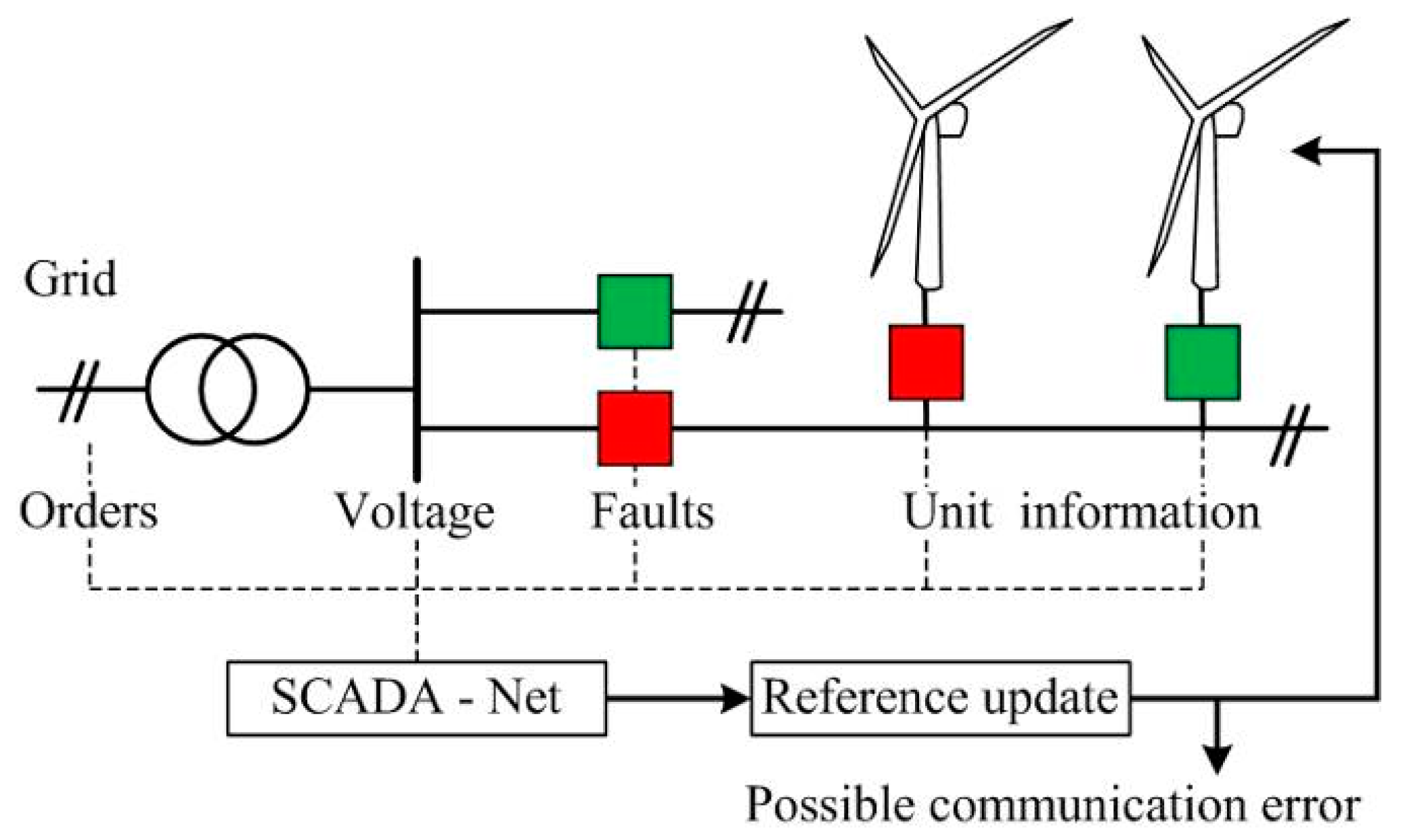
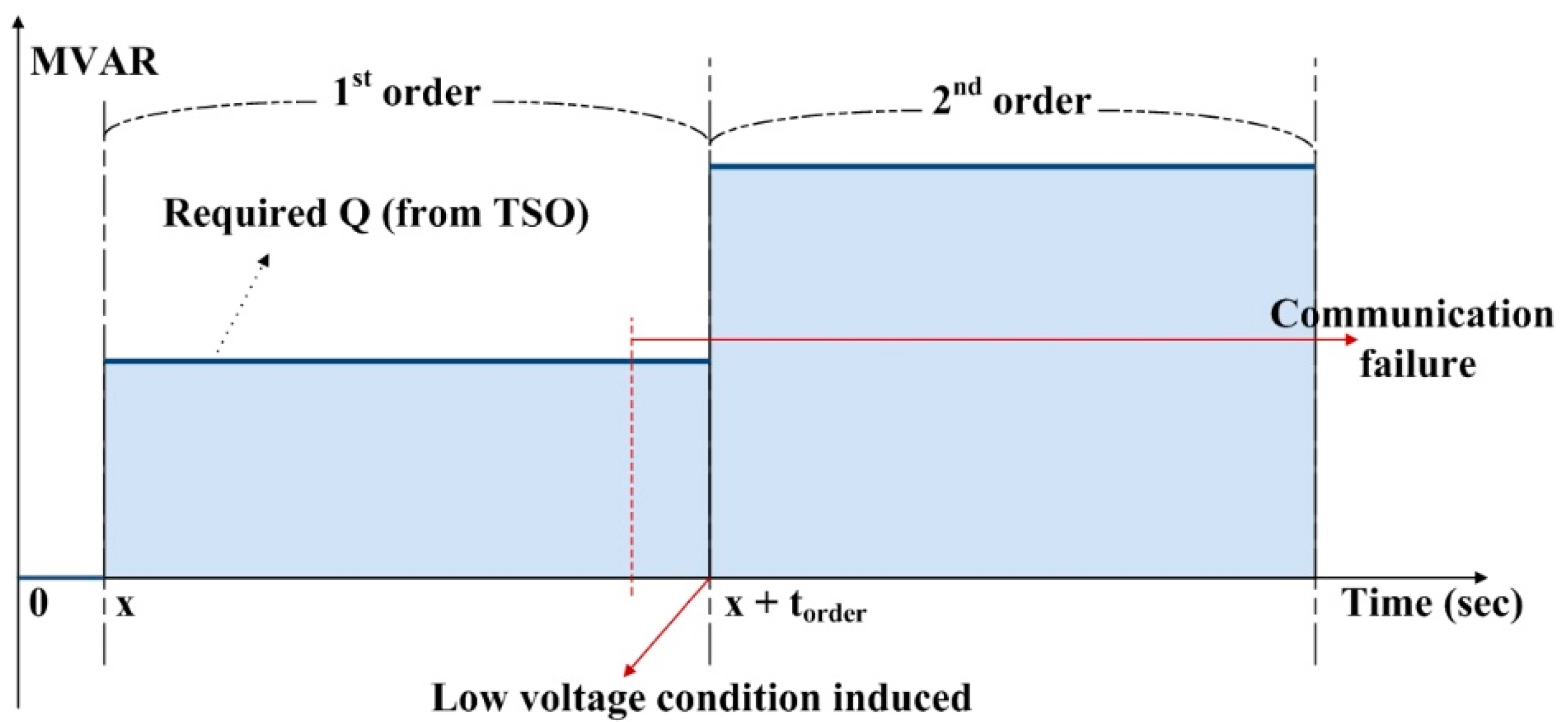
Figure 1 represents the flow of information that needs to be considered in the WFMS. By applying the acquired data, generated reference values are allocated to the whole generation system. However, since the signals flow through a communication network, there is the potential for information disruption within the update process. The aim of this paper is to provide an appropriate reactive power order modification to avoid potential disruptions. The required response actions in WFMS, in terms of order generation, are as follows:
  • Unexpected device malfunction and maintenance
  • Order changes, and low voltage conditions due to faults
  • Tripping, due to over voltage conditions.
As a reactive power order is formed to respond to voltage variations at the grid side, an automatic response mechanism is required, taking into account the above considerations. With this mechanism, the previous allocation plan can be operated within the designated compensation range during communication failure.

2.2. General Framework for Reactive Power Allocation

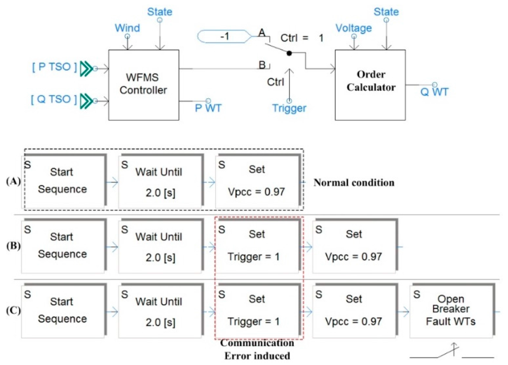
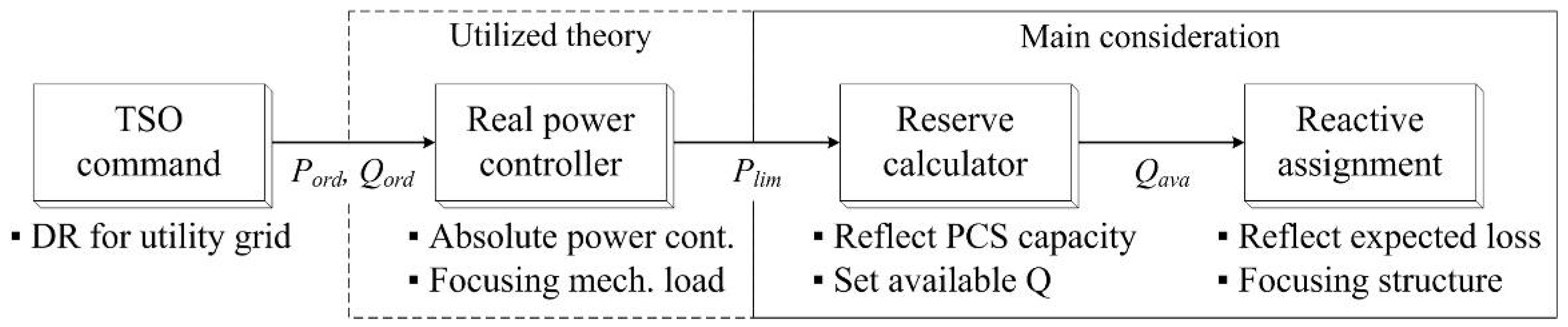
The WFMS in this paper adopts a real power prediction and limitation plan. This provides available real power to TSO as an utilizable value. TSO have to maintain power balance between demand and supply with the expected profile of the wind farm, and designates the maximum output power of the WFMS, to set the reference signal for each wind turbine. Each unit in the wind farm can be managed individually, and excessive real power can be regulated by pitch control.
Figure 2 describes the power control concept in WFMS. Firstly, the TSO sends the required wind farm level quantity to the WFMS. The central controller primarily assigns a maximum profile to each turbine. The WFMS then designates the reference signal as a maximum profile for each single turbine. The turbine then has to follow the limitation signal, before reaching the next stage. Considering the dependence of reactive power control on real power quantity, this control process has the advantage of aiding converter operations in the calculation of reactive power reserve in real time operation. The real power signal is directly utilized in the reactive power assignment process to predict real power loss and voltage variation.
The allocation plan in Reference [18] considers the reactive power reserve of the entire wind farm. Therefore, a precise capability update plan can enhance usability under practical operating conditions. Added to the composed basic proportional distribution plan, order modification focuses on the main objective function, based on changed system structures.

2.3. Based Algorithm for Reative Power Allocation

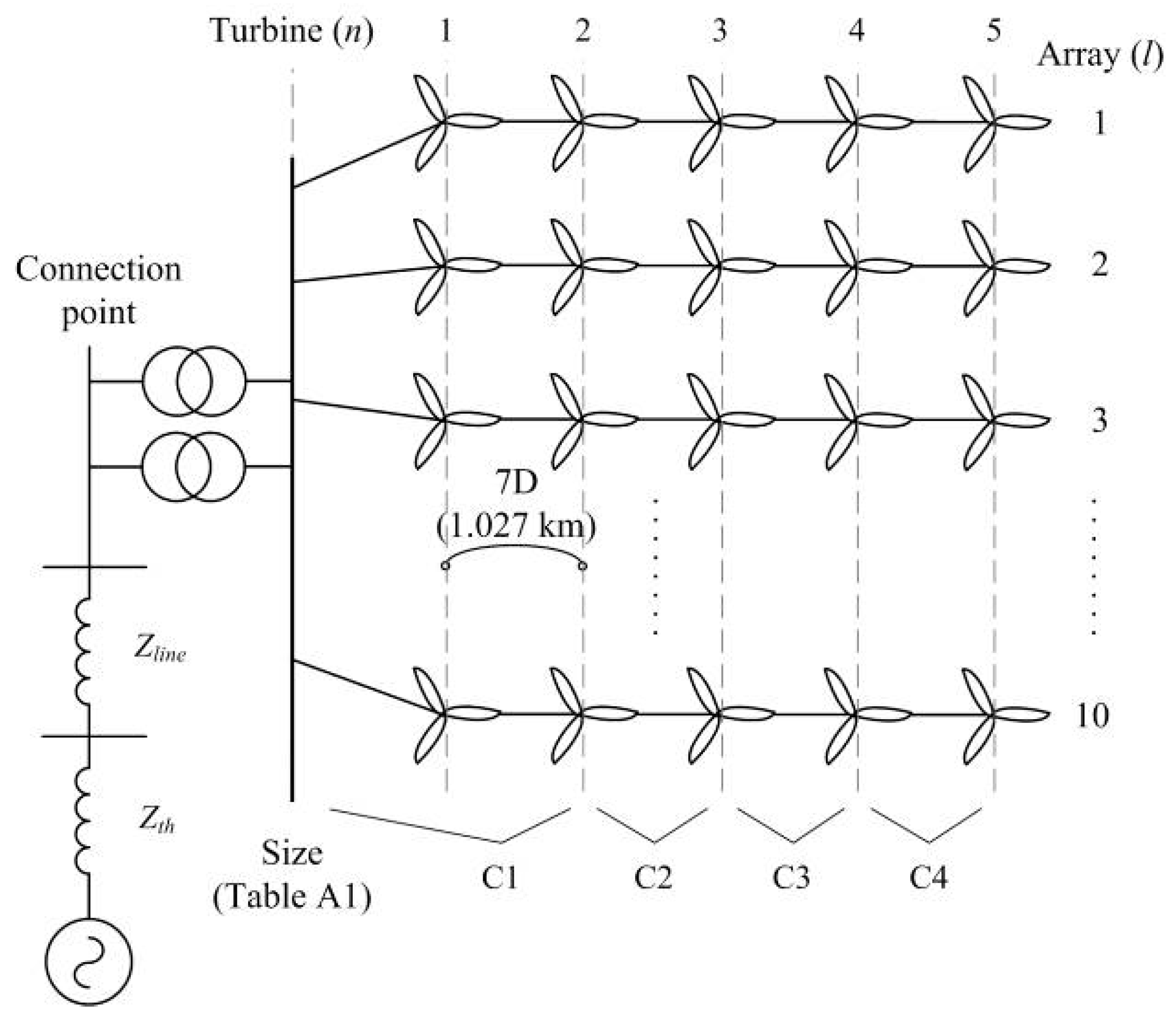
Electrical loss minimization is based on a fast optimization method, using a linearization process. In the radial structure of the wind generation system, the central controller is designed to minimize sectional loss by generating suitable references—deciding each proportion in accordance with the electric components of the layout. Therefore, the reactive power allocation coefficient that are expected to supply by each turbine should be continually updated. The proportion of the entire reactive power order can be segmented as shown in the following equation:
Q o r d e r = l = 1 L n = 1 N Q r e f ( l , n )
Q r e f ( l , n ) = η l n Q l
where, Qorder is the entire required reactive power order of the wind farm, n is the node number in each array, Ql is the allocated reactive power to array l. The reactive power allocation coefficient of each turbine in Reference [18] can be summarized in the following equation:
η l n = r n n + 1 r H n + r n n + 1 ( 1 η l n 1 )
η l n = r n n + 1 r H n + r n n + 1 ( i f   n = 1 )
where, rn∙n+1 is the line resistance between connection points of WT n and n + 1, rH is the line resistance relative to the connection height of the turbine.
The coefficients are affected with the number of WTs and these values were modified with PI controller in this paper. The expected reactive power supply of the array is allocated according to an incremental loss technique. The reference quantity of each array is fixed when the incremental values of the equation below become equal:
d L o s s d Q 1 = d L o s s d Q 2 = = d L o s s d Q l = λ
where electrical loss by reactive power is established with a variable composed by the resistance components, as follows:
L o s s ( Q ) = α Q 1 2 + β Q 2 2 + + γ Q L 2
The value need to be stored as a data form within the designated period until a recalculating process updates it, and this value has uncertainties which could not be considered in emergency situations, such as voltage dips within the grid side. Based on this, several automatic response equations can be designed to cope with the special conditions of the electrical network. A stabilized reactive power supply is obtained through an automatic order modification algorithm, when a state of unavailability for the command deriving process occurs, due to communication failure. To achieve this, the algorithm should be established with its own measurable value, including electric flow and voltage level. The appropriate reactive requirements for a turbine are derived through the voltage condition of the connected node.
The V-Q modal analysis is frequently used to solve issues in reactive power flow and AC voltage [19]. The fast decoupled method can linearize the system value, according to the voltage angle and quantity. The power flow equations are given by:
[ Δ P Δ Q ] = [ J P δ J P U J Q δ J Q U ] [ Δ δ Δ U U ]
If the power variation is neglected, the change of the required reactive power can be rewritten as:
Δ Q r e q = ( J Q U J Q δ J P U J P δ ) Δ U U
where, Qreq is the practical required quantity (including mismatches by cables) of a certain array. This component also can be divided with several reactive power flow rates, as:
Δ Q r e q = Δ Q G n + Δ Q n n + 1 + Δ Q C n
where, QGn is the reactive power reference of the wind turbine at node n, Qn∙n+1 is the reactive power flow between node n and n + 1, and QCn is the reactive power injection at node n from the line capacitance.
When we ignore the reactive power generation from the cable, the rate of change of the required reactive power at a certain node can allocate by following previously calculated coefficient. In this case, if the turbine controller utilizes the previously defined coefficient, a wind turbine can solely update the additionally required reactive power reference, by following the main objective. The changed order has an interaction formula with the measured flow and the voltage variation at a subordinate bus, using a linearized component, as in Equation (9):
Q G n = Q G n + η l n [ ( J Q U J Q δ J P U J P δ ) Δ U U Δ Q n n + 1 ]
This can lead to a prompt calculation process, which is a usable option in a quick response mechanism.

2.4. Proposed Modification Algorithm

To achieve a continuous assignment plan along with a wide area-based generation system, a self-modification method for the communication state has to be composed. The major issue for a large-scale wind farm is calculation reliability. Therefore, repetitive emergency responses for every single communication error could potentially have negative connotations in terms of reliability. As mentioned above, an active modification method will be introduced in this section for reducing emergency operations, caused by a variety of issues.
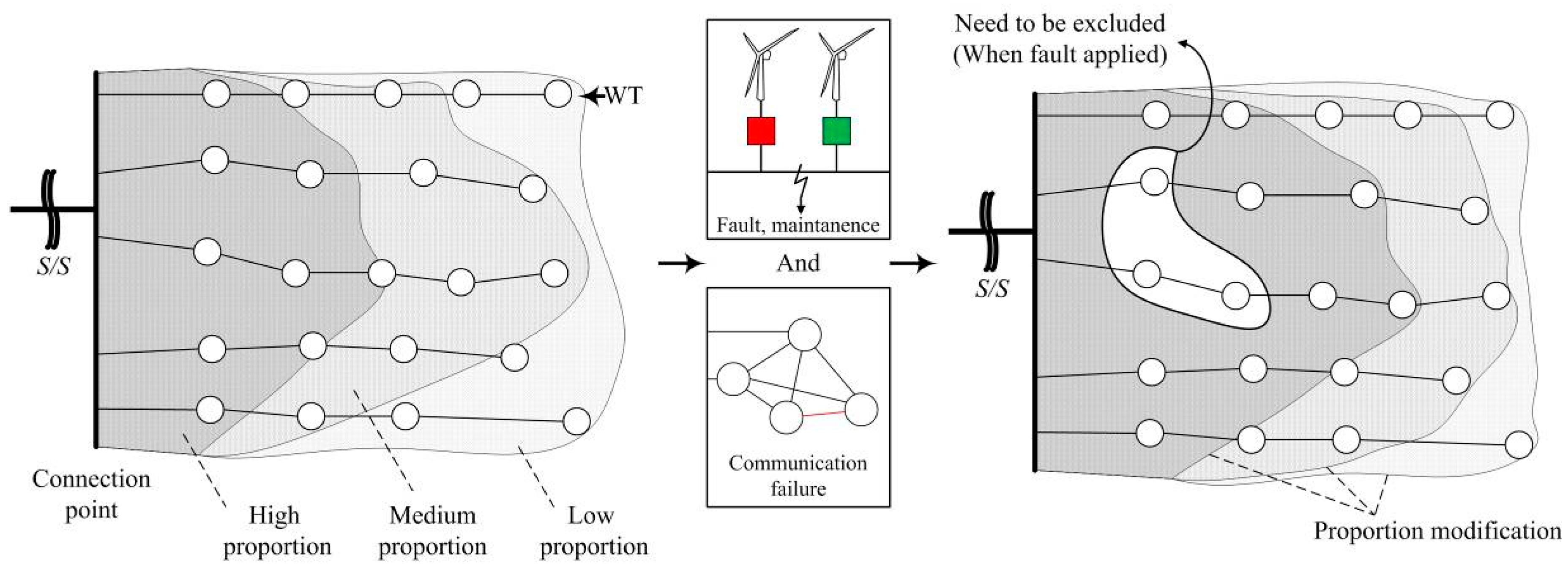
Figure 3 shows the concept of a self-modification process of reactive power allocation plan. As the allocation method is based on a loss minimization plan, the adjacent wind turbines from the connection point provide a large portion of the reactive power supply. As mentioned previously, this proportional value is usable in converter operations during communication failure. However, owing to practical issues, some turbine units may become unable to provide reactive power. In this state, without modification by a central subsystem, the previously calculated proportions will be classed as an improper signal, and unable to handle the voltage variation at certain nodes. To compose an appropriate compensation plan, the self-modification algorithm has to take these potential conditions into account.
The modification plans need to be amended with imposed values and measurable data, like the composed equation. In the case of the equation seen in the previous section, the main improvement is the availability of an autonomous modification method for reactive power supply when voltage variation conditions occur. However, this simple updating plan cannot satisfy the relevant quantities when power conversion devices at the turbines are unavailable. The inclusion of further processes, such as calculating the state of the upper unit, can lead to appropriate proportion modifications, offering a smoother reactive management plan without the need for additional support. This modification is represented by Equations (10) and (11).
η l n = η l n + η c o m ( 0 η l n 1 )
η c o m = ( J Q U J Q δ J P U J P δ ) Δ U p r e Δ U U Δ Q n n + 1 Q r e q
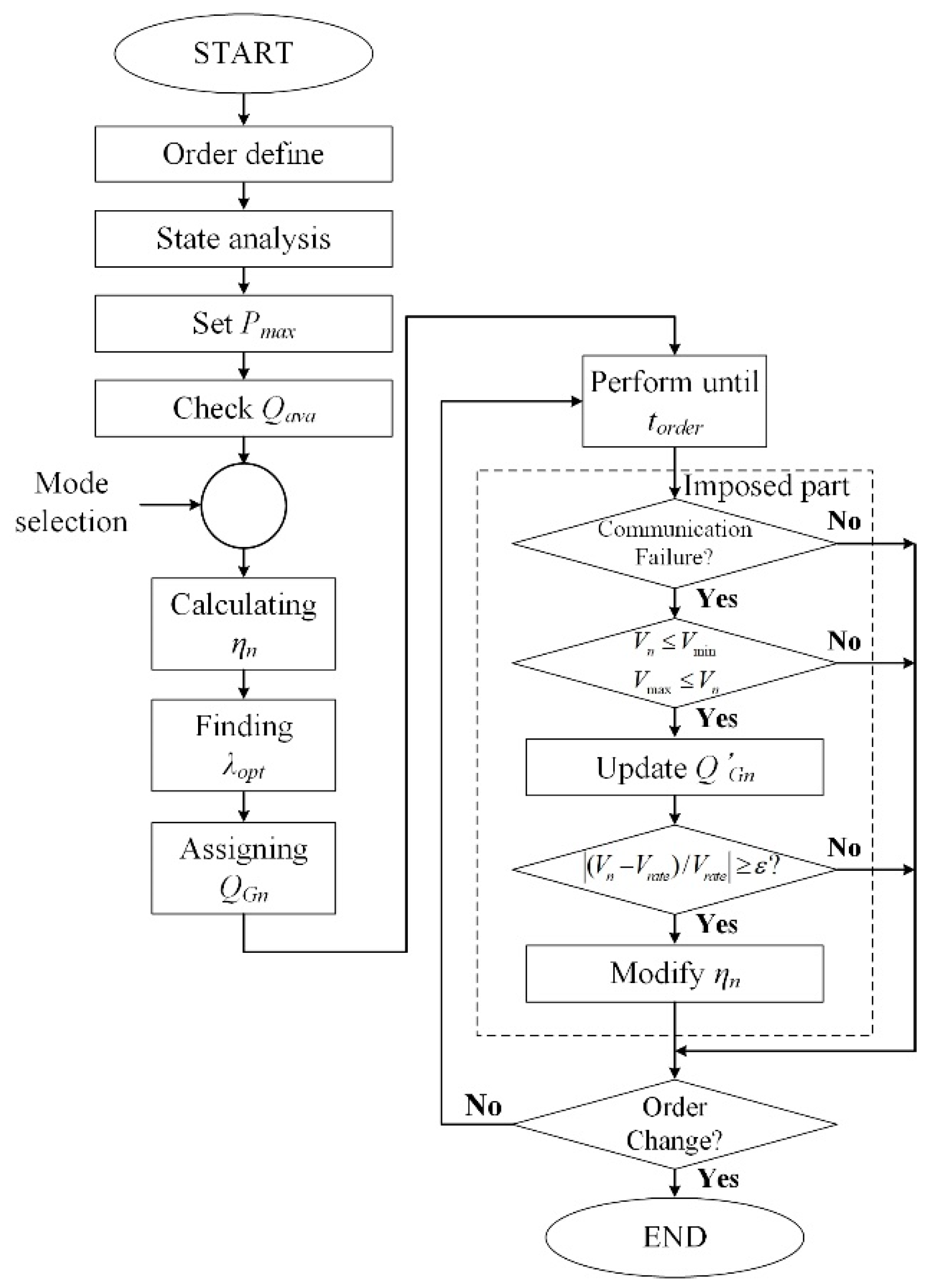
Figure 4 shows the whole reactive power control algorithm, including the proportion modification processes. As an option of the WFMS, the supervisory controller can check the current status, and define a curtailment value to confirm the reactive power reserve. The reactive power reserve in this paper follows the power factor (pf) limitation scheme, as shown in Equation (12). The operator can check the reactive power reserve using the maximum value for the real power that is individually designated from the power prediction process.
| Q a v a | = 1 p f 2 S p c s
where, Qava is the available reactive power reserve, and Spcs is the power conversion capacity of the converter (MVA). After calculating the proportion of each wind turbine, the imposed optimization process can be used as a selectable option by the system controller. Each wind turbine receives the calculated signal as a reference value, and utilizes it in a reactive current control process, before the next order is imposed. Unless it is considering an unpredictable state, the order will reflect the unprepared voltage condition, and the modification can be processed by the re-calculation in the algorithm.
The proposed section is applied in stages, taking three conditional statements into account. An initial non-response in communication logic acts as a trigger signal to the proposed control part. If there is a discrepancy in the networking subsystem, the self-modification logic will check the voltage variation to determine whether to revise the references or not. As mentioned above, the modification process is divided into categories of simple reference modification and proportional change. To consider further proportional modifications, the restoration rate of the voltage level needs to be checked. This modification can be carried out quickly, due to the linearized components of the imposed layout. The imposed part can be performed within a single generation unit. The control module in the verification part also has to consider a potential independent state.

3. Case Studies

3.1. System Configuration

To check the proposed algorithm and its related schemes, an EMTDC simulation was configured within a composed wind farm layout. A 7 MW/8 MVA full-converter-based wind turbine was utilized to compose a 350 MW wind farm system. The real power control processes were based on the WFMS, which utilized the curtailment option for matching imposed power demand. Figure 5 shows the entire layout, while Table 1 shows a basement system, including the main transmission line for the utility grid. The equivalent source of the entire power grid is incorporated by considering the short circuit ratio (SCR), which is used to estimate the robustness of the system. Further system configurations are equal to the previously analyzed wind farm layout (Table A1). The cable data set is utilized from the website of Reference [20], and the straight line distances for each array are described in Table A2.
Table 2 describes the designed verification processes that analyze the response improvement of the proposed method. The simulation time is designed to be 4.75 s, which includes a short initialization time, and an order changed point for verification. To estimate the main improvements of the proposed reactive power control scheme, an initial stable wind speed is applied in order to calculate full-extraction conditions. The low voltage condition, and related reactive power order changes, are then gradually imposed on the WFMS, causing reactive power reference variations.
Figure 6 shows the verification concept. If the changed references at next sequence (the sequence interval was named as torder) are not appropriately transferred to each wind turbine, in the case of the previous controller, the wind turbine controller refers to the previous reference, even if it involves TSO order variations. To check the order modification method, the communication error section is configured before the low voltage condition is induced as described in Table 3. The wind turbine trip condition is also considered, in the case of C. The tripped wind turbine is designated with consideration to the highest proportion of the reactive power in the array 1 (WT1). Additionally, array 5, which has the highest proportion of the entire reactive power supply in the wind farm, is protected by an over-riding trip switch system which is triggered in emergency situations. Figure 7 shows the modular designs and control sequences of each case study in PSCAD. In order to check the modification ability, some sequences are gradually integrated. Each signal is separately imposed, to configure the aforementioned severe conditions on the reactive power control.

3.2. Simulation Results

3.2.1. Basic Simulation

In order to estimate the modification effect in terms of reactive power supply, the comparison has to be processed along with the non-applied control scheme. The reactive power supply capability needs to be checked, as well as the voltage condition, including the connection point of the wind farm. Figure 8 shows the general reactive power supply process, using both the aforementioned allocation method, and the related voltage conditions. These exemplary curves were selected to show the highest variation conditions (array 1 has the longest connection distance, which also implies the largest voltage variation). As described in the simulation design, case A includes the voltage drop condition and the relevant order change. In general states, as shown in Figure 8, the modified signal, composed from the central controller, aptly manages the induced voltage variation. Consider the maximum reactive power reserve for each WT is nearly 2.5 MVAR (0.95 pf utilized for calculating limit); both full support and compensation are represented in displayed curves.

3.2.2. Imposing Communication Failure

Without the central controller, each wind turbine has to follow the previously generated references. An emergency stop for reactive power can be applied, but this kind of solution is unable to handle the changed condition, as shown in Figure 9. Cases B and C deal with communication problems, rendering the controller unusable. The changed voltage condition cannot affect individual references, even though the upper controller still modifies the values. Figure 10 shows the (a) reactive power supply modification, and (b) related voltage condition, at the same section under the proposed method. Each wind turbine measures the variation condition, and modifies its own references, using the imposed control delay (in this case, 0.1 s).
The modified references, as described above, follow the imposed proportional value, which is generated from the loss minimization plan (the closer wind turbines receive more references than those at a greater distance). According to the modified references, the additional reactive power supply is processed, and the voltage condition is saturated to a reasonable value, within 0.5 s. Because every wind turbine accepts the modified condition appropriately, the rated voltage level at the connection point is easily recovered.

3.2.3. Imposing Detachment Situation

In situations where the detachment of several wind turbines occur, due to unexpected faults and communication errors, this modification has to be maintained. Figure 11 and Figure 12 represent the case C analysis: As the first wind turbine in array 1 is detached due to a fault, the entire reactive power supply capability of array 1 is significantly reduced. Figure 11b shows an increase in the previously measured voltage drop in array 1, case B. This situation can be resolved if the modification method independently changes its proportion. Figure 12a illustrates this changed reference, using the supplied reactive power quantity. After the first reference is induced, each wind turbine takes additional references, in comparison with the first state. The previous reactive power reference for the first wind turbine is then distributed to the remaining wind turbines. Hence, further reliable results are derived in terms of reactive power supply. This result is intended to be a loss minimization technique that can lead to a continuous management process, irrespective of whether unexpected communication errors occur or not.

3.2.4. Summary of Results

From the simulation results, we can observe improvements in response time in the event of communication failure. Table 4 shows the numerical results. The non-applied cases show a constant reactive power supply. In particular, since case A includes feedback control, the reactive power supply quantity corresponds exactly with the TSO order. Although the reactive power supply quantities from the modification processes are not equal to case A, the wind farm is able to increase the quantity, without additional compensation devices.
Within a small number of iteration processes, the self-modification method finalizes the reactive power supply quantity, and handles the PCC voltage in the rated condition.

4. Conclusions

A reactive power reference modification method for wind farms, based on a previous allocating system, was introduced. The basic theory of the allocation method was derived from a selected loss minimization technique. The modification has followed the utilized proportional allocating plan, and shown conformity, in terms of a self-updating process for reactive power references. Even if a general wind system does not require an active support mode, in terms of reactive power, self-diagnosis algorithms for large-scale distribution networks can help to avoid communication errors.
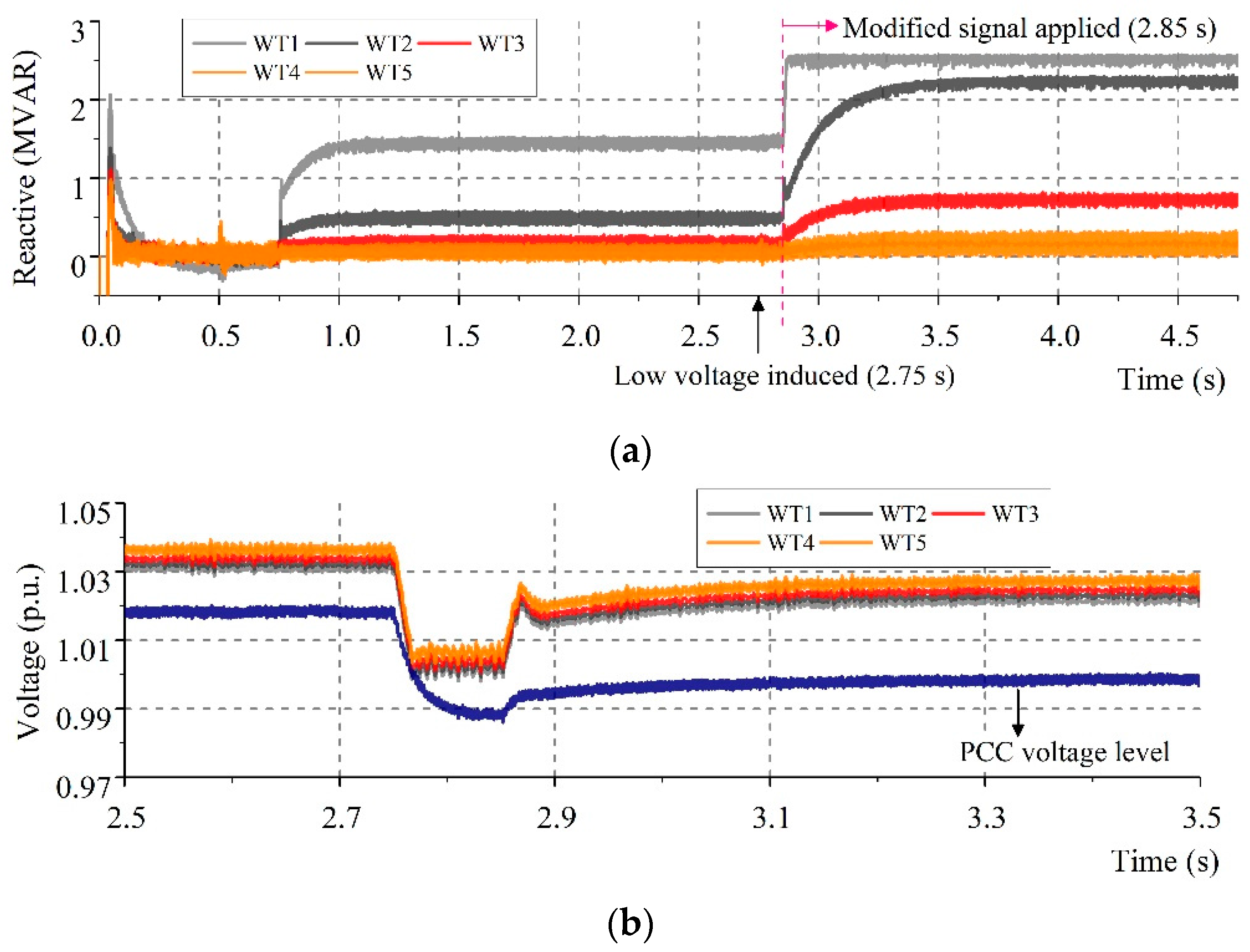
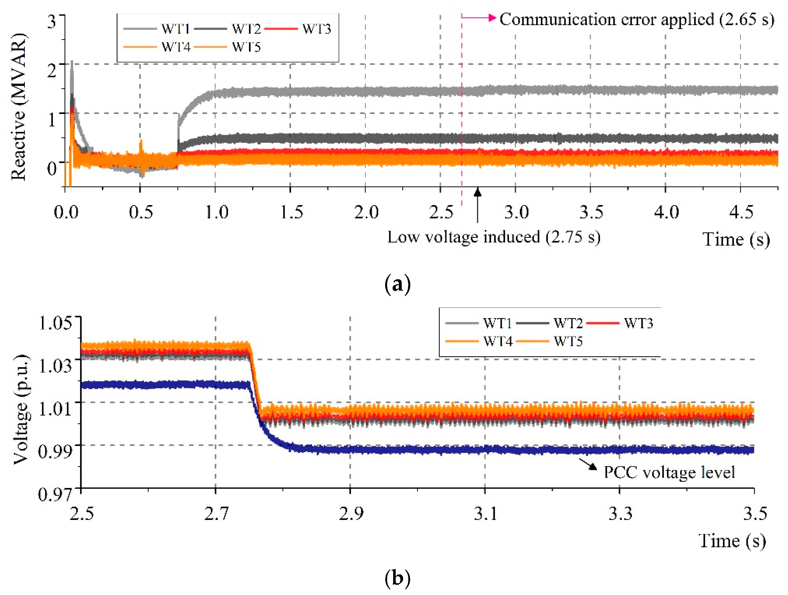
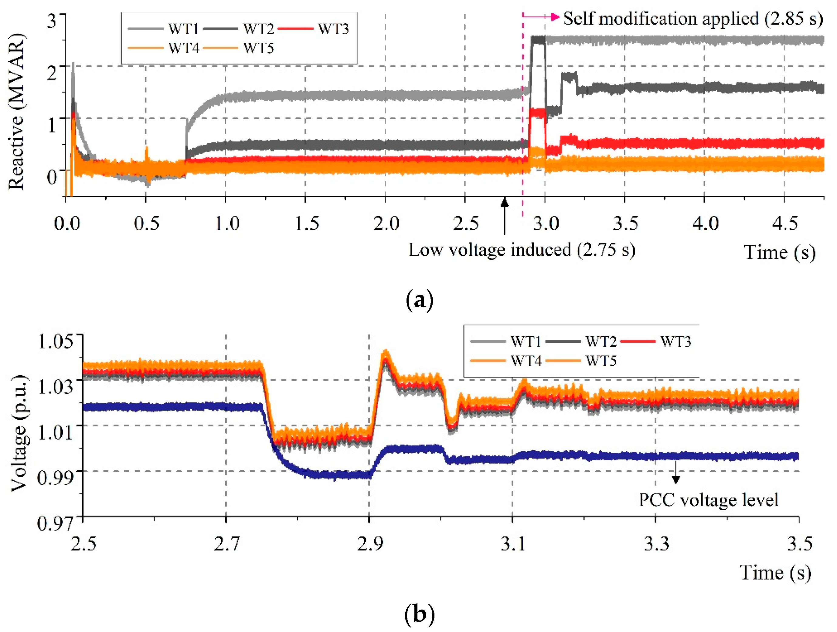
The order modification can be expanded to similar order management methods, and here, utilized a reactive power management process, analyzed some case studies. The general even-dispatch method was not considered in case studies due to the fact the designed network considered 50 WTs (since every WT display same profile modification, when we consider its scale, it is inappropriate analysis). From our simulations, it can be deduced that the modified reference signal contributes to the stabilized condition of the connection point. Since reactive power will be a major ancillary service in future wind farm systems, these support capabilities must be backed up by an additional security algorithm.

Acknowledgments

This work was supported by Korea Electric Power Corporation grant (R17XA05-4) and Human Resources Program in Energy Technology of the Korea Institute of Energy Technology Evaluation and Planning granted financial resource from the Ministry of Trade, Industry & Energy, Korea (No. 20174030201540).

Author Contributions

The main optimization algorithm and modification method were proposed by Seungmin Jung. The experiment results were collected and analyzed by Yeuntae Yoo, Taehyung Kim, Jae-Hyeong Lee, Minhan Yoon and Gilsoo Jang.

Conflicts of Interest

The authors declare no conflict of interest.

Appendix A

Table A1. Numerical transmission line data.
Size (m2)Allowed Current (A)Resistance (ohm/km)Inductance (mH/km)Capacitance (µF/km)
95 (C1)2910.1930.420.17
120 (C2)3300.1530.410.18
240 (C3)4700.07540.360.23
400 (C4)6270.0470.340.28
1000 (C0)11000.01760.30.24
Table A2. Straight-line distance between S/S and first wind turbine.
Array NumberDistance (m)Array NumberDistance (m)
133476574
226757984
3201081595
4136692249
5793102918

References

  1. Sideratos, G.; Hatziargyriou, N.D. An Advanced Statistical Method for Wind Power Forecasting. IEEE Trans. Power Syst. 2007, 22, 258–265. [Google Scholar] [CrossRef]
  2. Tian, J.; Su, C.; Soltani, M.; Chen, Z. Active power dispatch method for a wind farm central controller considering wake effect. In Proceedings of the IEEE Conference on Industrial Electronics Society, Dallas, TX, USA, 29 October–1 November 2014; pp. 5450–5456. [Google Scholar]
  3. Muyeen, S.M.; Takahashi, R.; Murata, T.; Tamura, J. A Variable speed wind turbine control strategy to meet wind farm grid code requirements. IEEE Trans. Power Syst. 2010, 25, 331–340. [Google Scholar] [CrossRef]
  4. Miao, L.; Wen, J.; Xie, H.; Yue, C.; Lee, W. Coordinated control strategy of wind turbine generator and energy storage equipment for frequency support. IEEE Trans. Ind. Appl. 2015, 51, 2732–2742. [Google Scholar] [CrossRef]
  5. Morales, A.; Robe, X.; Sala, M.; Prats, P.; Aguerri, C.; Torres, E. Advanced grid requirements for the integration of wind farms into the Spanish transmission system. IET Renew. Power Gener. 2008, 2, 47–57. [Google Scholar] [CrossRef]
  6. Hartmann, B.; Dan, A. Cooperation of a Grid-Connected Wind Farm and an Energy Storage Unit—Demonstration of a Simulation Tool. IEEE Trans. Sustain. Energy 2012, 3, 49–56. [Google Scholar] [CrossRef]
  7. Senturk, O.S.; Helle, L.; Munk-Nielsen, S.; Rodrigues, P.; Teodorescu, R. Power capability investigation based on electrothermal models of press-pack IGBT three-level NPC and ANPC VSCs for multimegawatt wind turbines. IEEE Trans. Power Electron. 2012, 27, 3195–3206. [Google Scholar] [CrossRef]
  8. Zhao, C.; Guo, C. Complete-independent control strategy of active and reactive power for VSC based HVDC system. In Proceedings of the IEEE Power & Energy Society General Meeting, Calgary, AB, Canada, 26–30 July 2009; pp. 1–6. [Google Scholar]
  9. Zhao, B.; Guo, C.X.; Cao, Y.J. A Multiagent-Based Particle Swarm Optimization Approach for Optimal Reactive Power Dispatch. IEEE Trans. Power Syst. 2005, 20, 1070–1078. [Google Scholar] [CrossRef]
  10. Ullah, N.R.; Bhattacharya, K.; Thiringer, T. Wind farms as reactive power ancillary service providers—Technical and economic issues. IEEE Trans. Energy Convers. 2009, 24, 661–672. [Google Scholar] [CrossRef]
  11. Seungmin, J.; Gilsoo, J. Development of an Optimal Power Control Scheme for Wave-Offshore Hybrid Generation Systems. Energies 2015, 8, 9009–9028. [Google Scholar]
  12. Zhou, D.; Blaabjerg, F.; Lau, M.; Tonnes, M. Thermal behavior optimization in multi-MW wind power converter by reactive power circulation. IEEE Trans. Ind. Appl. 2014, 50, 433–440. [Google Scholar] [CrossRef]
  13. Ma, K.; Liserre, M.; Blaabjerg, F. Reactive power influence on the thermal cycling of multi-MW wind power inverter. IEEE Trans. Ind. Appl. 2013, 49, 922–930. [Google Scholar] [CrossRef]
  14. Ross, K.; Hopkinson, K.; Pachter, M. Using a distributed agent-based communication enabled special protection system to enhance smart grid security. IEEE Trans. Smart Grid 2013, 4, 1216–1224. [Google Scholar] [CrossRef]
  15. Zamani, M.A.; Yazdani, A.; Sidhu, T.S. A communication-assisted protection strategy for inverter-based medium-voltage microgrids. IEEE Trans. Smart Grid 2012, 3, 2088–2099. [Google Scholar] [CrossRef]
  16. Fazeli, A.; Sumner, M.; Johnson, M.C.; Christopher, E. Real-time deterministic power flow control through dispatch of distributed energy resources. IET Gener. Transm. Distrib. 2015, 9, 2724–2735. [Google Scholar] [CrossRef]
  17. Ibrahim, H.M.; El Moursi, M.S.; Huang, P.H. Adaptive Roles of Islanded Microgrid Components for Voltage and Frequency Transient Responses Enhancement. IEEE Trans. Ind. Inform. 2015, 11, 1298–1312. [Google Scholar] [CrossRef]
  18. Fadul, J.E.; Hopkinson, K.M.; Andel, T.R.; Sheffield, C.A. A trust-management toolkit for smart-grid protection systems. IEEE Trans. Power Deliv. 2014, 29, 1768–1779. [Google Scholar] [CrossRef]
  19. Seungmin, J.; Gilsoo, J. A Loss Minimization Method on a Reactive Power Supply Process for Wind Farm. IEEE Trans. Power Syst. 2017, 32, 3060–3068. [Google Scholar]
  20. 6–36 kV Medium Voltage Underground Power Cables. Nexans, 2009. Available online: http://www.nexans.co.uk/UK/files/Underground%20Power%20Cables%20Catalogue%2003-2010.pdf (accessed on 27 February 2009).
Figure 1. Online management network and data flow.
Applsci 08 00068 g001
Figure 2. Core control flowchart of the proposed method.
Applsci 08 00068 g002
Figure 3. Schematic description for proposed plan.
Applsci 08 00068 g003
Figure 4. Entire control flow chart, including newly imposed calculation.
Applsci 08 00068 g004
Figure 5. Wind farm configuration and related values.
Applsci 08 00068 g005
Figure 6. Reactive power control concept in simulated scenarios.
Applsci 08 00068 g006
Figure 7. Modular description in the simulation program (PSCAD).
Applsci 08 00068 g007
Figure 8. Reactive power supply from array 1 and voltage condition in case A, with (a) reactive power supply, and (b) voltage variation.
Applsci 08 00068 g008
Figure 9. Reactive power supply from array 1 and voltage condition in case B—conventional algorithm, with (a) reactive power supply, and (b) voltage variation.
Applsci 08 00068 g009
Figure 10. Reactive power supply from array 1 and voltage condition in case B—modified algorithm, with (a) reactive power supply, and (b) voltage variation.
Applsci 08 00068 g010
Figure 11. Reactive power supply from array 1 and voltage condition in case C—conventional algorithm, with (a) reactive power supply, and (b) voltage variation.
Applsci 08 00068 g011
Figure 12. Reactive power supply from array 1 and voltage condition in case C—modified algorithm, with (a) reactive power supply, and (b) voltage variation.
Applsci 08 00068 g012aApplsci 08 00068 g012b
Table 1. Basic information for test system.
Transmission SystemCable SizeC0
Cable length20 (2 line)Km
Main GridSCR15
X/R15
Base voltage154kV
Wind Farm ConfigurationConnection height-C1 size149.7M
Base voltage22.9kV
Table 2. Imposed numerical value in basic case study.
Simulation TimeStart-up0.75s
torder2s
Total simulation time4.75s
Utilized Wind Profile350 (full extraction)MW
Low Voltage ConditionInduced time2.75s
Voltage level0.97p.u.
Reactive Power Order Change (TSO)First order50MVAR
Second order100MVAR
Table 3. Designed situations for analysis.
ClassificationCommunication ErrorWind Turbine Trip
Case AN/AN/A
Case BApplied at 2.65 sN/A
Case CApplied at 2.65 sApplied at 2.85 s
Table 4. Measured result of each case study.
ClassificationProposed ControllerIteration NumberFinalized Reactive Supply [MVAR]Saturated Voltage-PCC [p.u.]
Case A--1001.015
Case BNone-49.660.99
Applied590.671.01
Case CNone-36.720.986
Applied782.50.99

