Article

Hiding Stealth Optical CDMA Signals in Public BPSK Channels for Optical Wireless Communication

1
Department of Electrical Engineering, National Formosa University, Yunlin County 632, Taiwan
2
Department of Electrical Engineering, National Cheng Kung University, Tainan City 701, Taiwan
3
Department of Photonics Engineering, National Cheng Kung University, Tainan City 701, Taiwan
*
Author to whom correspondence should be addressed.
Appl. Sci. 2018, 8(10), 1731; https://doi.org/10.3390/app8101731
Submission received: 20 August 2018 / Revised: 19 September 2018 / Accepted: 20 September 2018 / Published: 25 September 2018

Abstract

:
A new optical steganography scheme is proposed that transmits a stealth optical code-division multiple-access (OCDMA) signal through a public binary phase-shift keying (BPSK) channel. Polarization beam splitters and arrayed waveguide gratings are used to implement a spectral-polarization coding (SPC) system with an incoherent optical source. We employ a Walsh–Hadamard code as the signature code of the user who wants to transmit stealth information using the system. A free space optical link applied to this system maintains the polarization states of light during propagation. The secret data are extracted using correlation detection and balanced subtraction in the OCDMA decoder of the intended receiver, and the other signal from the public channel is reduced by the OCDMA decoder. At the demodulator of the public channel, BPSK demodulation eliminates the stealth signal so that the public channel is not affected by the stealth signal. The two signals cannot interfere with each other. The results of this study show that our proposed optical steganography system is highly secure. The stealth signal can be favorably hidden in the public channel when the average source power of the stealth signal, public noise, and public signal are −5, −3, and 0 dBm, respectively.

1. Introduction

With the increasing application of computers in different areas of life and work, information security has become an important concern. To enhance security in the physical layer of an optical network, several approaches have been investigated, such as quantum private communication, optical encryption, and optical steganography [1,2,3,4,5,6]. Steganography is one of the methods that have received attention in recent years. The word steganography, which is derived from Greek, literally means “covered writing”. The main goal of steganography is to hide information sufficiently well such that any unintended recipients do not suspect that the steganographic medium contains hidden data [7]. This is a major distinction between steganography and the other methods of improving security. For example, optical encryption allows a signal to be encrypted with low latency; thus, the recipient requires a key to read the information. However, each person notices the information by seeing the coded signal; that is, the method cannot prevent the signal from being detected. In some cases, the system is already in danger of being decrypted if an eavesdropper knows about the existence of the signal. Steganography provides an additional layer of security by hiding the data transmission underneath the steganographic medium. The physical layer security has become an important issue of communication security technique because it is cost-efficient without sacrificing much data rate. It takes the advantages of channel randomness nature of transmission media to achieve communication confidentiality and authentication [8,9,10].
Steganography operations have been performed on different cover media such as images, audio, text, and video [11]. In recent years, new research into methods for secure communication over existing public fiber-optic networks has been conducted. Using a concept similar to steganography, the secure signal is processed by a particular technique called optical steganography and can be hidden under the noise floor of a public network. Optical steganography is realized by transmitting a private signal hidden in the existing public channel to increase the secrecy of the communication system. One of the first methods using the concept of optical steganography was proposed by Wu and Narimanov [12,13]. In this method, the signal is hidden using spread spectrum techniques. Several researchers have worked with various secret transmissions over different types of public network. For example, Kravtsov (2007) proposed a method of secure stealth transmission over a wavelength-division multiplexing (WDM) network [14]. Wu (2008) discussed coherent spectral-phase-encoded OCDMA signal transmission in a WDM network [15]. Wang (2011) investigated stealth transmission over a public differential phase-shift keying (DPSK) channel [16]. Tait and Wu (2014) demonstrated an optical steganography technique based on amplified spontaneous emission noise [17].
The basic approach of optical steganography is to temporally stretch the pulses of a signal using high-dispersion elements. The amplitudes of the signal pulses are dramatically decreased after the stretching so that the signal can be hidden underneath the public signal and system noise. However, once the existence of the hidden channel is revealed, eavesdroppers may take measures to process the stealth signal; therefore, the stealth channel may be weak against eavesdropping. To enhance the security of the stealth channel, additional security measures are required against eavesdroppers. For this, optical code-division multiple-access (OCDMA)—which has been successfully applied in optical steganography—is a great choice [17,18,19,20]. The research uses the techniques of polarization modulator based code-shift-keying (CSK) data modulation for OCDMA codec. The wavelength selective switch is used for optical en/decoding and it shows the stealth signals can transmitted over a 40-km wavelength-division multiplexing optical fiber link [21]. The other investigation uses two joint routing and resource allocation algorithms for stealth and ordinary services in optical networks. The technique improves the success rate of optical steganography by increasing more wavelength consumption [22].
In this study, the stealth signal was encoded using a spectral-polarization-coded OCDMA (SPC-OCDMA) technique, which employs polarization beam splitters (PBSs) and arrayed waveguide gratings (AWGs) as the encoders and decoders. Chirped fiber Bragg gratings (CFBG) were used as the pulse stretcher and compressor to implement optical steganography. To restore the stealth signal, the public signal was removed using the balanced correlation detection/subtraction mechanism conventionally adopted in OCDMA decoders. A binary phase-shift keying (BPSK) demodulator was used to reject stealth OCDMA interference and system noise. Thus, the stealth signal and noise affect the public network only slightly. The remainder of this paper is organized as follows. In Section 2, the theories and principles of the proposed optical steganography scheme is described. In Section 3, the proposed optical steganography configuration setup and simulation results are introduced. In Section 4, system performance with stealth signal in the proposed system is interpreted, and brief conclusions are presented in Section 5.

2. The Theories and Principles Background of the Proposed Stealth Communication Approach

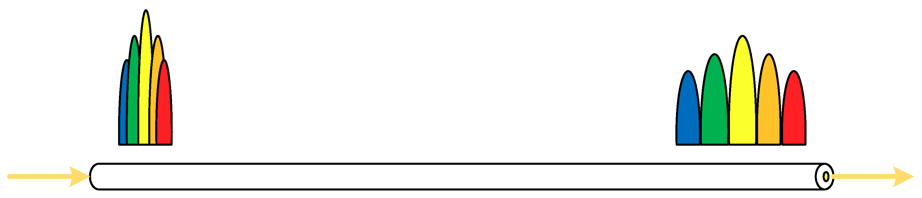
2.1. Chromatic Dispersion

Chromatic dispersion in an optical medium is a phenomenon in which the group velocity of light propagating through the medium depends on the light’s wavelength. Let us consider a situation wherein a pulse is transmitted along a single-mode fiber. In an optical fiber, different spectral components of the pulse travel with slightly different group velocities. Consequently, they arrive at the fiber output at different times, even though they started at the same time. Figure 1 illustrates the phenomenon of chromatic dispersion caused by light propagation in a single-mode fiber. A pulse at frequency ω passes through a fiber with length L after a time delay τ = L/νg. The group velocity νg is given by
νg = /,
where β is the propagation constant. The range of pulse broadening for a fiber of length L can be expressed as [23]
Δ τ = d τ d ω Δ ω = d d ω ( L ν g ) Δ ω = L d 2 β d ω 2 Δ ω ,
where Δω is the spectral width of the pulse. The pulse spectral width Δω is usually replaced by the range of wavelengths Δλ emitted by the optical source. Then, Equation (2) can be written as
Δτ = −(2πc/λ2)βLΔλ = DLΔλ,
by using the relations ω = 2πc/λ and Δω = (−2πc/λ2)Δλ, where β” is the second derivative with respect to λ and D is the dispersion parameter with units ps/(nm·km). A negative dispersion parameter indicates that lightwave with longer wavelength travels faster than lightwave with shorter wavelength.

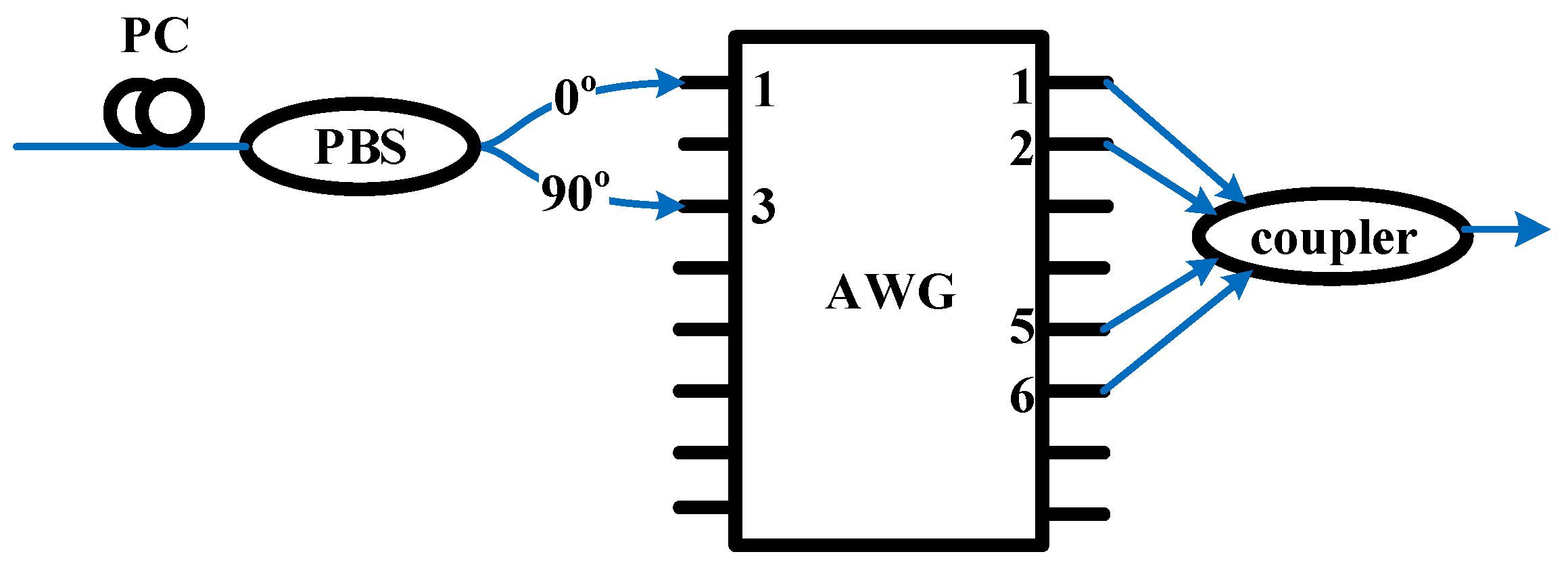
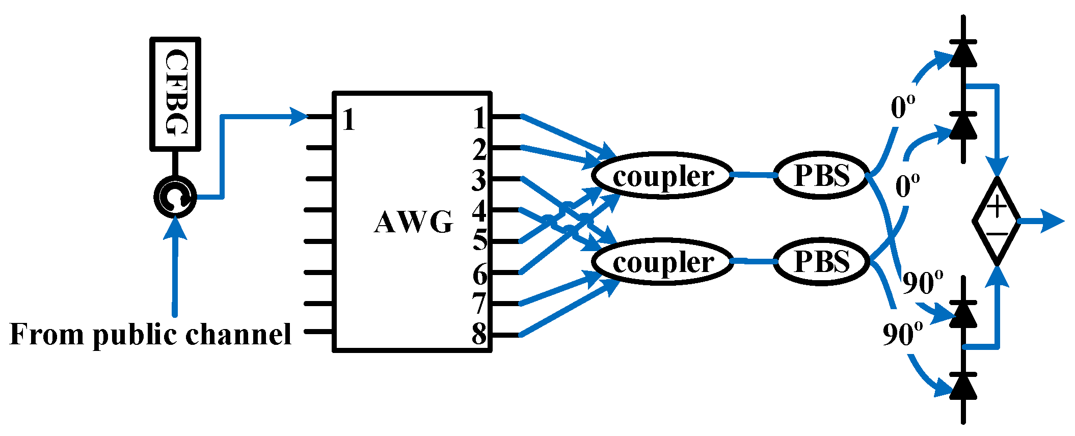
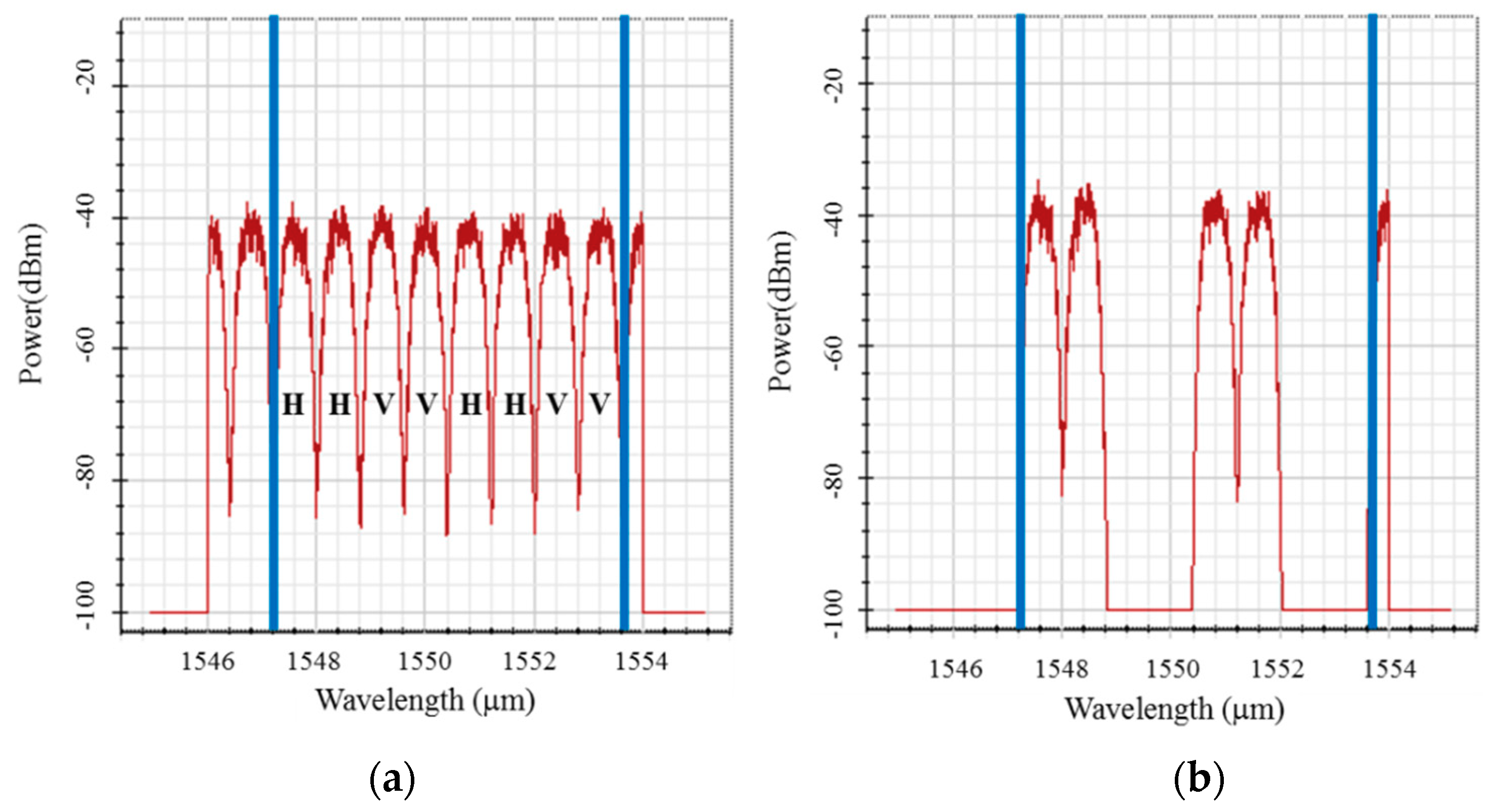
2.2. Spectral-Polarization Coding Using Walsh–Hadamard Codes

In spectral amplitude coding Spectral-amplitude coding (SAC)-OCDMA systems, a specific signature address code is assigned to each user to code the amplitude of the source spectrum. Walsh–Hadamard codes are quasi-orthogonal codes used in SAC-OCDMA systems [24,25] and are obtained by selecting the row of the Walsh–Hadamard matrix comprising elements {1,0}. Each row except the first row contains N/2 zeros and N/2 ones, where N is the length of the codeword. An N × N Walsh–Hadamard matrix can be generated using the recurrence relation, which is given by
H N = [ H N / 2 H N / 2 H N / 2 H ¯ N / 2 ] ,
In the above Walsh–Hadamard matrix, the lower right matrix element H ¯ N / 2 defines a conjugate of the matrix element HN/2. It is clear that the autocorrelation value is N/2 and the cross-correlation value between different rows is N/4. Let us introduce the Walsh–Hadamard code correlation properties as follows:
R c c ( k , l ) = i = 1 N c k ( i ) c l ( i ) = { N / 2 , k = l N / 4 , k l ,
and
R c c ¯ ( k , l ) = i = 1 N c k ( i ) c ¯ l ( i ) = { 0 , k = l N / 4 , k l ,
where Ck is the code sequence in the kth row of the Walsh–Hadamard matrix. According to the property R C C ( k , l ) = R C C ¯ ( k , l ) for kl, a receiver is designed to perform correlation subtraction expressed as R C C ( k , l ) R C C ¯ ( k , l ) :
Z = R C C ( k , l ) R C C ¯ ( k , l ) = {   N / 2   ,   k = l 0 ,   k l ,
This equation shows that the influence from other users will be rejected.
In the SPC scheme, the source spectrum is encoded by orthogonal polarizations according to the specific signature address code. We employed a Walsh–Hadamard code to allocate a vertically or horizontally linear state of polarization (SOP) to each specified wavelength. The specific code sequence for the SPC-OCDMA system comprises Ck(H) and C k ¯ ( V ) , where H and V denote the vertical and horizontal polarization, respectively.
As shown in Figure 2, using the wavelength cyclic-shifted characteristic property of AWG routers represented in Equation (8), we can obtain C (H) = (1, 1, 0, 0, 1, 1, 0, 0) and C ¯ ( V ) = (0, 0, 1, 1, 0, 0, 1, 1) to form the SPC code of encoder #3. C (H) and C ¯ ( V ) correspond to code patterns (λ 1H, λ 2H, 0, 0, λ 5H, λ 6H, 0, 0) and (0, 0, λ3V, λ 4V, 0, 0, λ 7V, λ 8V), respectively. Therefore, the wavelength-coding patterns of the SPC code are (λ 1H, λ 2H, λ 3V, λ 4V, λ 5H, λ 6H, λ 7V, λ 8V) when a data bit 1 is transmitted and (0, 0, 0, 0, 0, 0, 0, 0) when a data bit 0 is transmitted. The subscripts of λij denote the ith wavelength encoded and the SOP:
(#input port + #output port − 1) mod N = #wavelength,

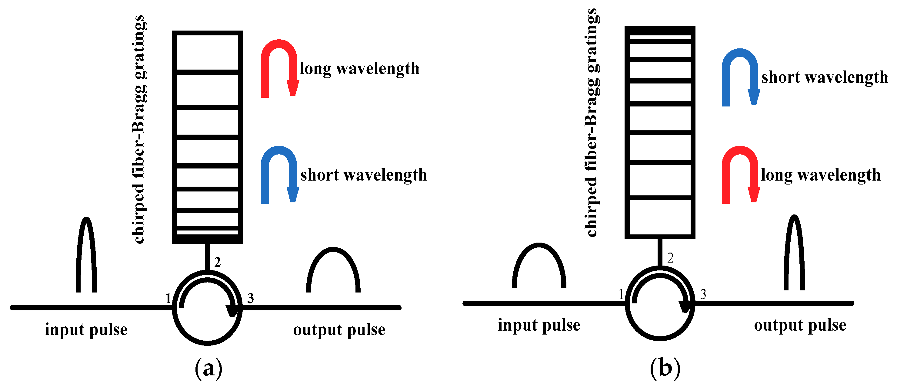
2.3. Chirped Fiber Bragg Gratings

As described in Section 2.1, dispersion leads to the pulse broadening of optical pulses propagating along a fiber and becomes a limiting factor for optical communication systems operating at high bit rates. Herein, we use the characteristics of dispersion to stretch the pulse; this transforms the stealth signal into a noise-like signal so that it can be buried in a public channel.
Figure 3 shows the structure of a CFBG [26]. A fiber Bragg grating is a periodic perturbation of the refractive index along the fiber length. The core of the fiber is exposed to an intense optical interference pattern to fabricate the Bragg gratings. When the incident light passes through the periodic structure, a narrow band of the optical field is reflected by continuous, coherent scattering from the variations in the refractive index. The strongest interaction occurs at the Bragg wavelength λB, which is given by
λ B = 2 n e f f Λ ,
where neff is the effective refractive index of the core and Λ is the grating period. The chirping of a fiber Bragg grating indicates changes in the period of the grating with distance.
As depicted in Figure 3a, the grating period increases along the fiber’s length so that shorter wavelengths are reflected nearer the input of the fiber, whereas longer wavelengths are reflected nearer the output. Thus, light with longer wavelengths is more delayed than light with shorter wavelengths. This CFBG structure produces positive dispersion. In contrast to positive dispersion, the structure of the CFBG in Figure 3b produces negative dispersion. CFBGs can provide a large dispersion with a small size. To provide the same dispersion in a standard single-mode fiber, the required length must be increased by a factor of 2000 [27], which can make the system more compact.

2.4. Free Space Optical Communication (FSO)

FSO is an optical communication technique for transmitting data in free space, such as air, vacuum, or outer space. The setup of an FSO system is similar to that of an optical fiber cable (OFC) network. The only difference between them is that the optical beams in an FSO network are transmitted through free air compared with glass in OFC networks. As shown in Figure 4, the fundamental structure of an FSO system comprises a laser, an electro-optic modulator (EOM), a lens design, and a detector. The laser is modulated using the EOM and the laser beam is converged onto the receiver by the lens.
FSO system performance is dependent on the transmission medium because of the presence of foreign elements such as rain, fog, haze, physical obstructions, scattering, and atmospheric turbulence [28].

3. The Proposed Optical Steganography System Setup and Simulation Results

The SPC-OCDMA system was simulated using Opti-System software (v 7.0). Opti-System is a software simulation kit from Optiwave™ (Nepean, OTT, Canada) that analyzes the performance of optical systems and networks. A schematic of the experimental setup is presented in Figure 5. The stealth signal is first encoded and then transmitted into the public channel. To simulate the system noise in a real optical network, a noise source is introduced to generate noise and couple it to the public and stealth signals. This enables convenient investigation of the impact of system noise on the stealth signal.

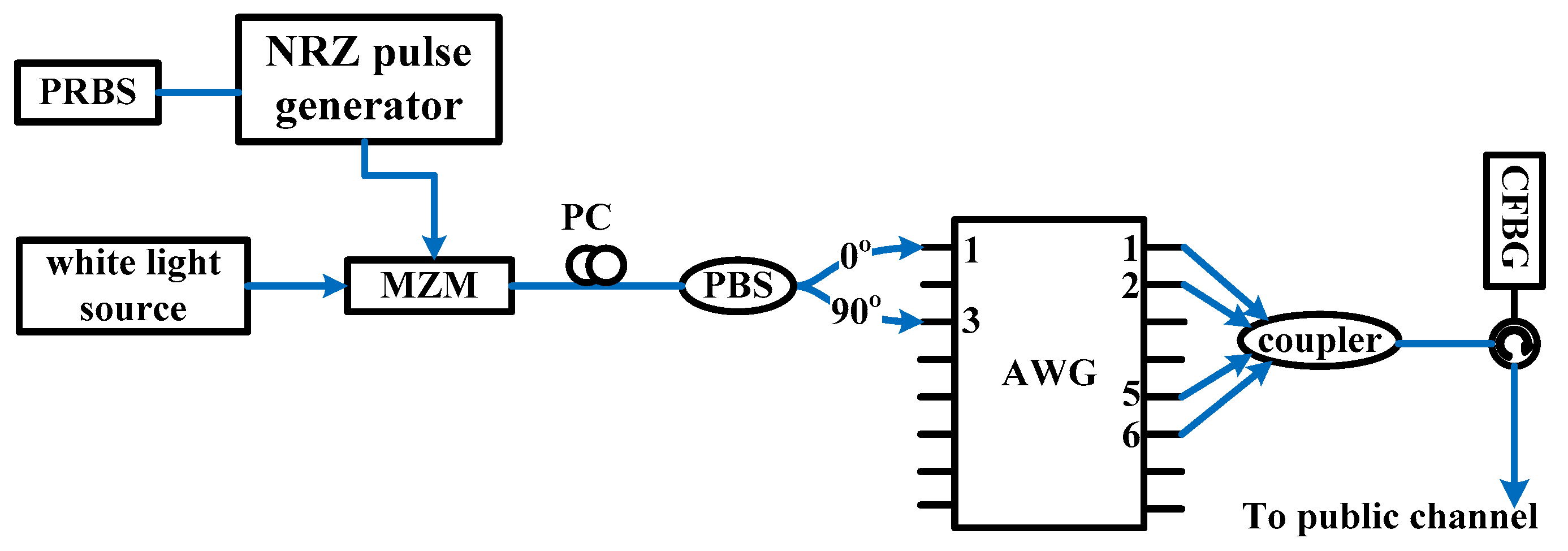
3.1. Structure of Public and Stealth Channels

BPSK is the simplest form of the phase-shift keying technique and is a digital modulation method that transmits data by changing the phase of the carrier wave. The phase difference of the carrier wave is 180° when transmitting data bits 1 and 0. Furthermore, the frequency of the carrier wave is typically 10 times the bit rate. We transmit a BPSK signal in the public channel to make the signal always exist irrespective of the data bit transmitted. The stealth signal is not exposed because of the disappearance of the public signal. Figure 6 presents the structure of the public channel.
In this structure, NRZ pulses are multiplied by a sinusoidal wave and the BPSK signal is generated. The following equation shows the general form of the BPSK signal:
S b ( t ) = 2 E b T b cos [ 2 π f c t + π ( 1 b ) ] ,   b =   0 ,   1 .
From the general form, we can conclude that binary data is conveyed using the following signals:
S 1 ( t ) = 2 E b T b cos ( 2 π f c t ) ,   for   bit   1 ,
S 0 ( t ) = 2 E b T b cos ( 2 π f c t + π ) = 2 E b T b cos ( 2 π f c t + π ) ,   for   bit   0 ,
where Eb is the energy per bit, Tb is the 1-bit duration, fc is the frequency of the carrier wave, and b is the data bit. Then, the BPSK signal drives a Mach–Zehnder modulator (MZM) to modulate a continuous-wave (CW) laser. To demodulate the public BPSK signal, the optical signal is first transformed into an electrical signal by the photodiode, following which the photocurrent is multiplied by cos(2πfct):
S 1 ( t ) cos ( 2 π f c t ) = 2 E b T b cos ( 2 π f c t ) cos ( 2 π f c t ) ,
S 0 ( t ) cos ( 2 π f c t ) = 2 E b T b cos ( 2 π f c t ) cos ( 2 π f c t ) ,
The term cos(4πfct) is filtered using a low-pass filter. The data bit is recovered by an appropriate thresholder. The transmitter in the stealth channel is illustrated in Figure 7. On–off keying (OOK) data are generated using a white light source, and the MZM is driven by a pseudorandom binary sequence (PRBS). A polarization controller is placed between the modulator and the PBS to adjust the SOP. The modulated signal is divided into mutually orthogonal SOPs by the PBS and then input into the AWG-based OCDMA encoder.
We input two orthogonal SOPs to different AWG input ports. According to the wavelength cyclic-shifted characteristic property of AWG routers detailed in Equation (8), we can obtain the spectrum encoded by the Walsh–Hadamard code Ck(H) and its complementary code C k ¯ ( V ) . The encoded stealth signals are combined using a coupler and passed through a CFBG for further pulse broadening to lower the peak power for effectively concealing the stealth channel beneath the public channel.
Figure 8 shows the structure of the proposed SPC decoder. To restore the stealth signal, the received signal is first passed through a CFBG, which is the same as that at the transmitter except with opposite dispersion. The stretched stealth signal is then compressed back into the original profile. Thereafter, the mutually orthogonal SOP components from the encoded spectrum are input to the AWG router for OCDMA decoding. The output ports of the AWG couple with the upper and lower couplers depending on the signature code Ck and its complementary code C k ¯ . With the PBS, the same SOPs of spectra are extracted for balanced detection. Furthermore, the detected electrical signal from the lower branch is subtracted from the corresponding signal from the upper branch. Finally, the stealth signal is obtained using the decoding mechanism.
The following equations detail the math analyses of the SPC decoding process. When transmitting data bit 1, the received signal is given by
R = C k ( H ) + C k ¯ ( V ) .  
The spectrum from the upper and lower couplers can be expressed as in Equations (16) and (17), respectively:
R C k = C k ( H ) ,
R C k ¯ = C k ¯ ( V ) .
According to the proposed structure, the spectra of Ck(H) and C k ¯ ( V ) are sent to the topmost and lowest photodiode, respectively. Consequently, the final photocurrent received is described by
i = 1 N C k ( i ) ( C k ¯ ( i ) ) = i = 1 N C k ( i ) + C k ¯ ( i ) = N ,
where N denotes the length of the codeword; here, we assume that each chip of the spectrum produces one unit current.
If another user transmits a signal with Walsh–Hadamard code Cl, the received signal is given by
R = C l ( H ) + C l ¯ ( V ) .  
Then, the spectrum from the upper and lower couplers can be expressed as
R C k = C l ( H ) C k + C l ¯ ( V ) C k ,
R C k ¯ = C l ( H ) C k ¯ + C l ¯ ( V ) C k ¯ .
Based on the decoder structure, the spectra of C l ( H ) C k , C l ( H ) C k ¯ , C l ¯ ( V ) C k , and C l ¯ ( V ) C k ¯ are sent to the first to fourth photodiodes, respectively. Consequently, the final photocurrent received can be written as
[ i = 1 N C l ( i ) C k ( i ) C l ( i ) C k ¯ ( i ) ] [ i = 1 N C l ¯ ( i ) C k ( i ) C l ¯ ( i ) C k ¯ ( i ) ] = 0 .
From the calculations, we observe that the photocurrent is zero at the first balance detection. Thus, only the user with the corresponding code can transmit the signal, with multiuser access interference from other users rejected.
The parameters of the simulation are as follows. To generate the public BPSK signal, an MZM is used to modulate a CW laser at 3 Gbps with a 27-1 PRBS. The center wavelength of the CW laser is 1549.2 nm. In the stealth channel, 1-Gbps OOK data are generated using a white light source followed by an MZM driven by a 27-1 PRBS. The modulated signal is encoded using an AWG according to a Walsh–Hadamard code with the length of the codeword being 8. We set the codeword to be (1, 1, 0, 0, 1, 1, 0, 0) for the vertical SOP and (0, 0, 1, 1, 0, 0, 1, 1) for the horizontal SOP. The wavelengths utilized are 1547.6, 1548.4, 1549.2, 1550, 1550.8, 1551.6, 1552.4, and 1553.2 nm, respectively.
As discussed in the Introduction, most previous studies on optical steganography have described stealth signals encoded by spread-spectrum OCDMA or phase-encoded OCDMA techniques and transmitted on existing public networks. Therefore, to help fill a gap in knowledge, we investigate the probability of applying other types of OCDMA techniques. The SAC is a promising OCDMA technique that provides high transmission rates with low system complexity and using a low-cost optical source. However, it is not easy using conventional technique to realize physical layer security of multi-wavelength OCDMA system. We compare the proposed SPC with SAC and demonstrate that the proposed SPC-OCDMA system can enhance the security of SAC-OCDMA.
The spectrum of the encoded signal is presented in Figure 9. Figure 9a shows the proposed SPC code pattern and Figure 9b displays the traditional SAC code. V and H represent vertical and horizontal linear SOP, respectively.
Figure 10 presents the spectrum of the public channel with and without the stealth signal. In Figure 10a, the peak of the spectrum is the public signal and the other peaks are system noise. Figure 10b,c indicates that the spectrum of SPC-OCDMA is flatter than that of SAC-OCDMA. In Figure 10c, the encoded signal is visible near the peak of the public signal. The spectrum of the public channel varies slightly after the SPC signal is transmitted in Figure 10a,b so that it can be buried in the public channel in the spectral domain.
The encoded stealth signals are combined using a coupler and passed through a CFBG for further pulse broadening to lower the peak power. To effectively conceal the stealth channel beneath the public channel, the CFBG is used to produce a total dispersion of 1600 ps/nm. The waveforms before and after this stretching are displayed in Figure 11, which shows that the pulse is broader and the signal power is much lower after stretching.
Figure 12 presents the waveform of the public channel in the time domain. The waveform reveals the necessity of adopting CFBGs. Figure 12a,b shows that the stealth signal can be favorably hidden in the public channel using a CFBG with 1600 ps/nm dispersion. Without dispersion, the existence of the stealth signal is exposed, as shown in Figure 12c.
The source powers of the stealth and public signals are −5 and 0 dBm, respectively. Figure 10 and Figure 12 demonstrate that the spectra and waveform of the public BPSK signal with and without the stealth signal are negligibly different when the noise power is −3 dBm. Therefore, the stealth signal can be buried underneath the system noise and transmitted in the public channel without being detected.

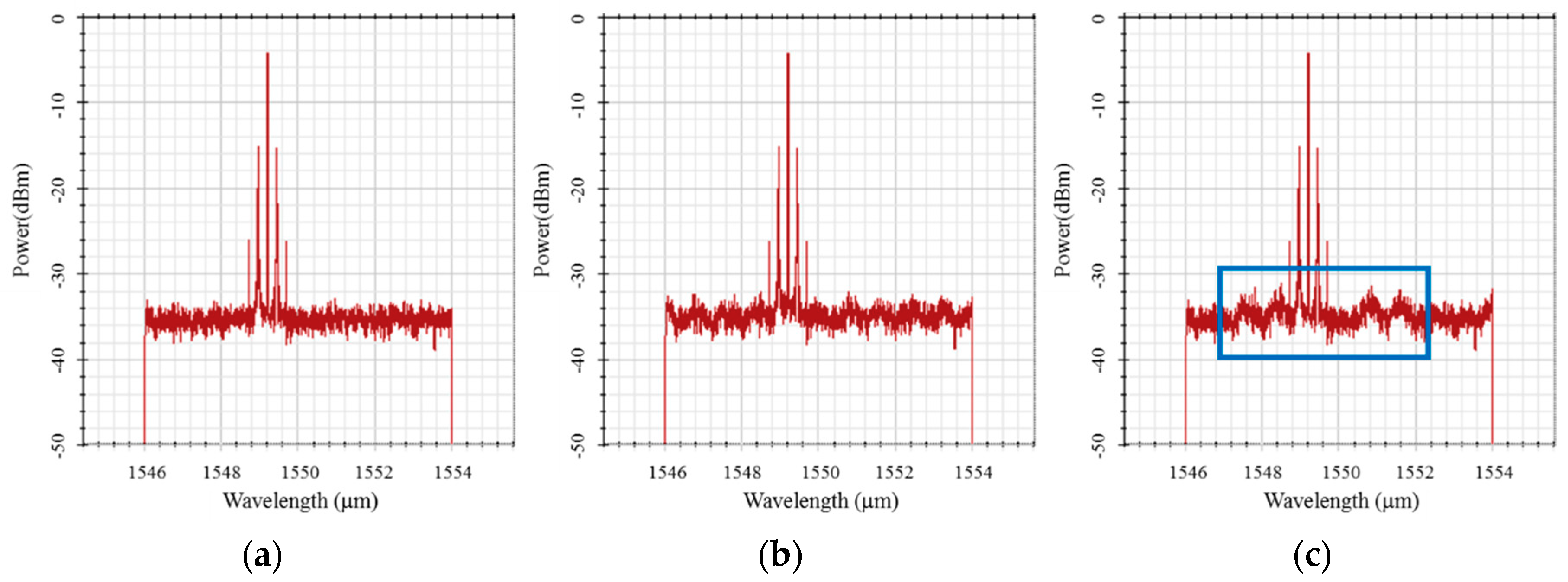
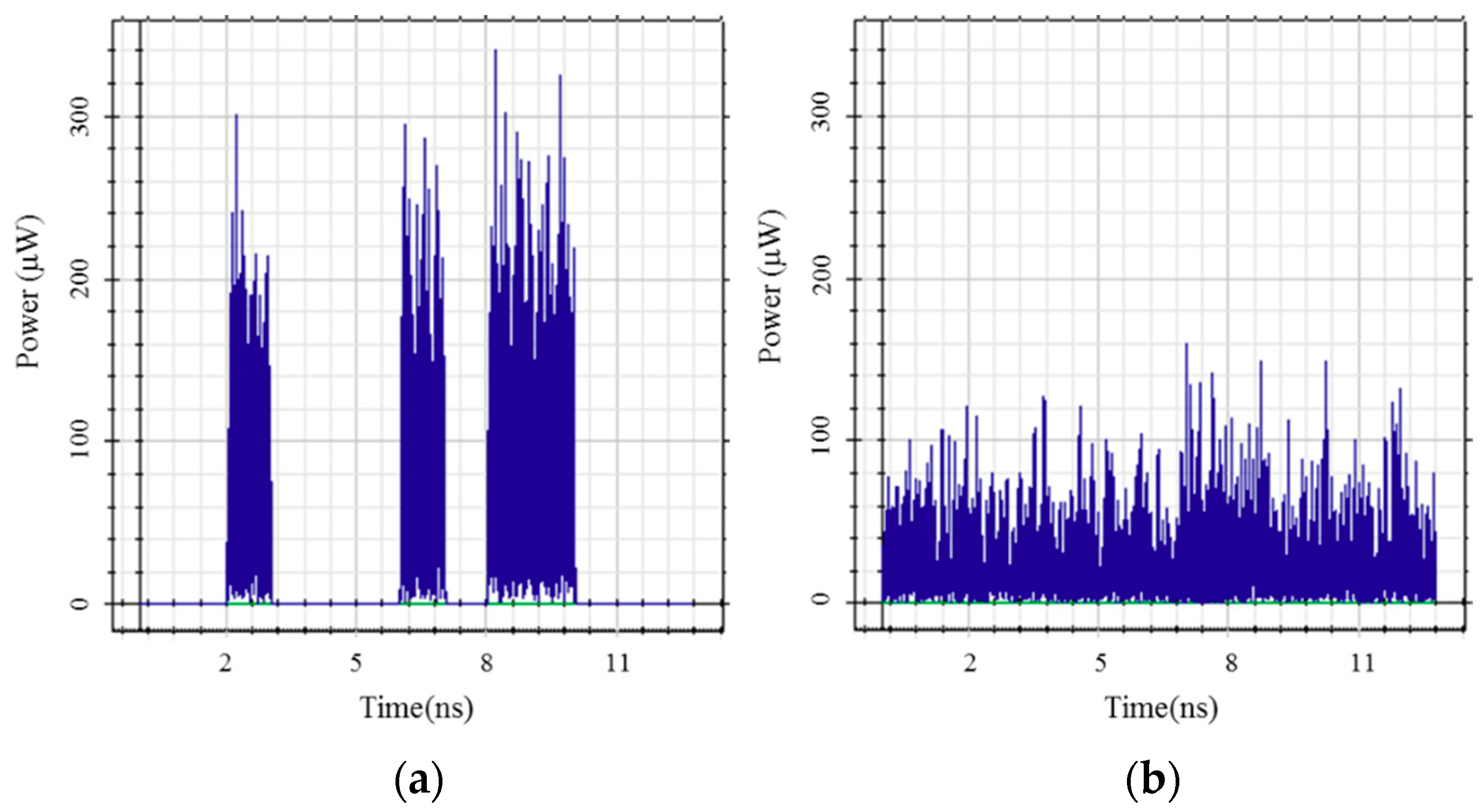
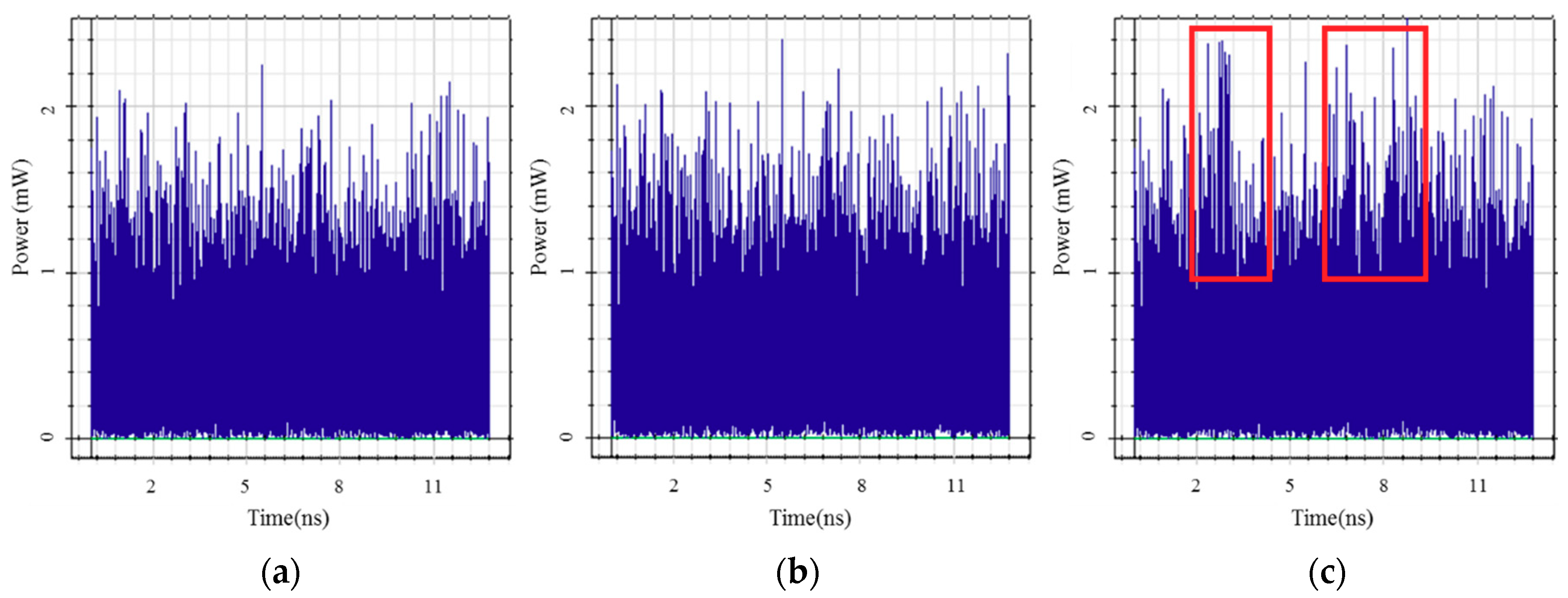
3.2. Interference Cancellation of Stealth and Public Signals

At the receiver side, a 3-dB optical coupler is used to split the mixed signal comprising the public and stealth signals into two portions. To detect the BPSK signal, the portion in the public receiver is sent to a BPSK demodulator. As shown in Figure 13, the BPSK demodulator comprises a sine generator and a low-pass filter. The photocurrent of the BPSK public signal and the stealth signal during a 1-bit period can be respectively expressed as follows:
S n ( t ) = 2 E b T b cos [ 2 π f c t + π ( 1 b ) ] , b = 0 , 1 ,
S s t ( t ) = I 0 r e c t ( t ) = { I 0 , 0 t T b 0 , o t h e r ,
where Eb is the energy per bit, Tb is the 1-bit duration, fc is the frequency of the carrier wave, b is the data, and I0 is the intensity of the photocurrent. Then, the mixed photocurrent is multiplied by cos(2πfct), following which the photocurrent of the stealth signal can be written as
S s t ( t ) cos ( 2 π f c t ) = I 0 cos ( 2 π f c t ) .
Compared with Equations (13) and (14), the stealth signal contains the term cos(2πfct). Because fc is much higher than the bit rate, the high-frequency terms are filtered out by the low-pass filter. Consequently, the public signal can be recovered successfully and relatively unaffected by the stealth signal.
To restore the stealth signal, the received signal is first passed through a CFBG, which is the same as that at the transmitter except with opposite dispersion. The stretched stealth signal is then compressed back to the original profile. At the decoder, the public BPSK signal is divided into mutually orthogonal SOPs with identical power by the PBS, which is designed according to the SOP of the CW laser. The power of the public signal from the upper and lower branches of the PBS is equal, as shown in Figure 14. For example, the electric field of the CW laser with linear +45 polarization is written as E(45°), and the PBS is designed to divide the light into two beams with horizontally linear polarization and vertically linear polarization. The electric fields of the two beams can be expressed as E(45°)cos45° and E(45°)sin45°. Next, the final subtraction after the photodiodes is given by
E(45°)cos45° − E(45°)sin45° = 0,
Thus, the public signal is eliminated by the double balance-difference detection. In the next section, we derive the signal-to-noise ratio (SNR) and bit-error rate (BER) to evaluate the system’s performance.

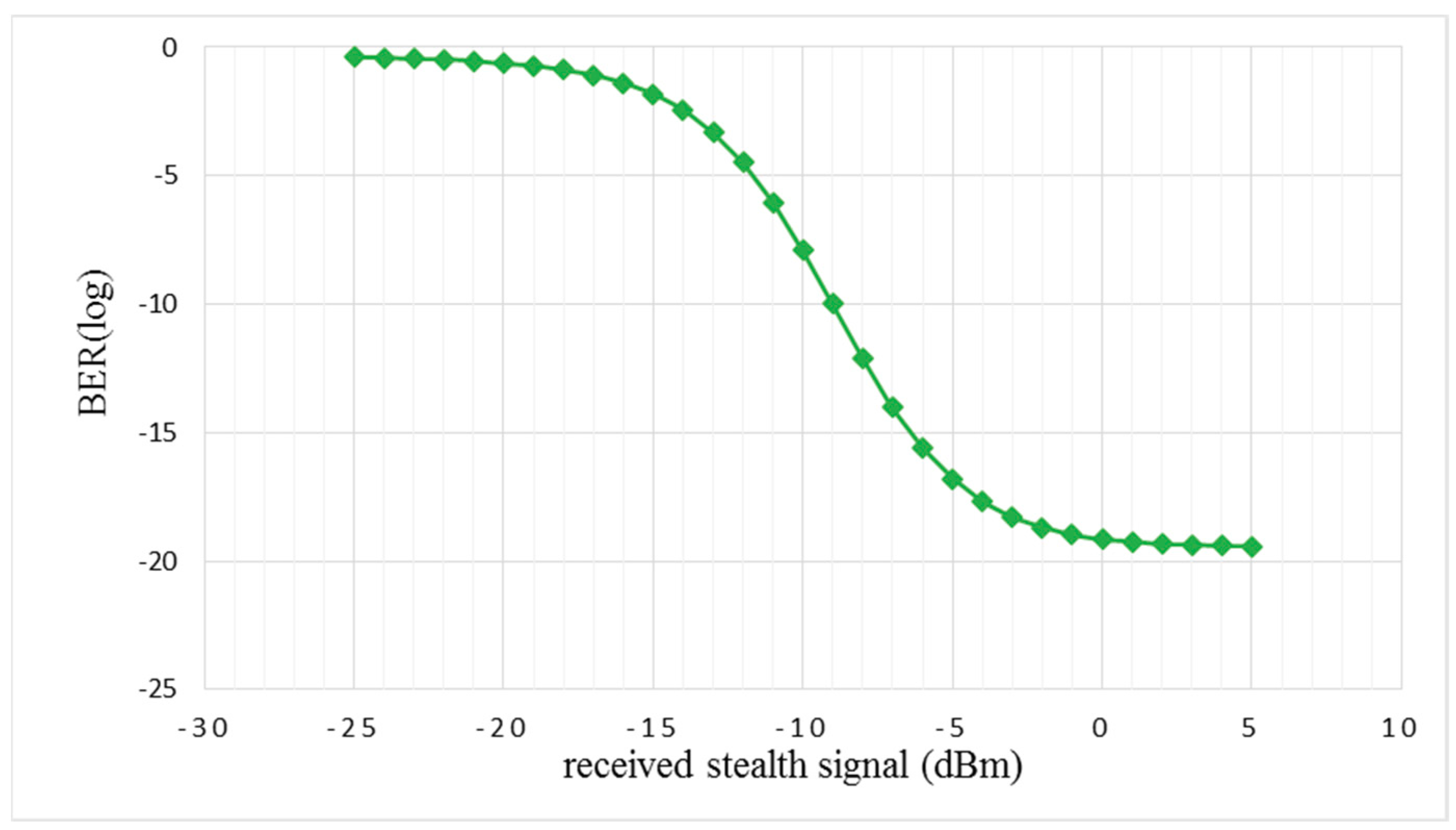
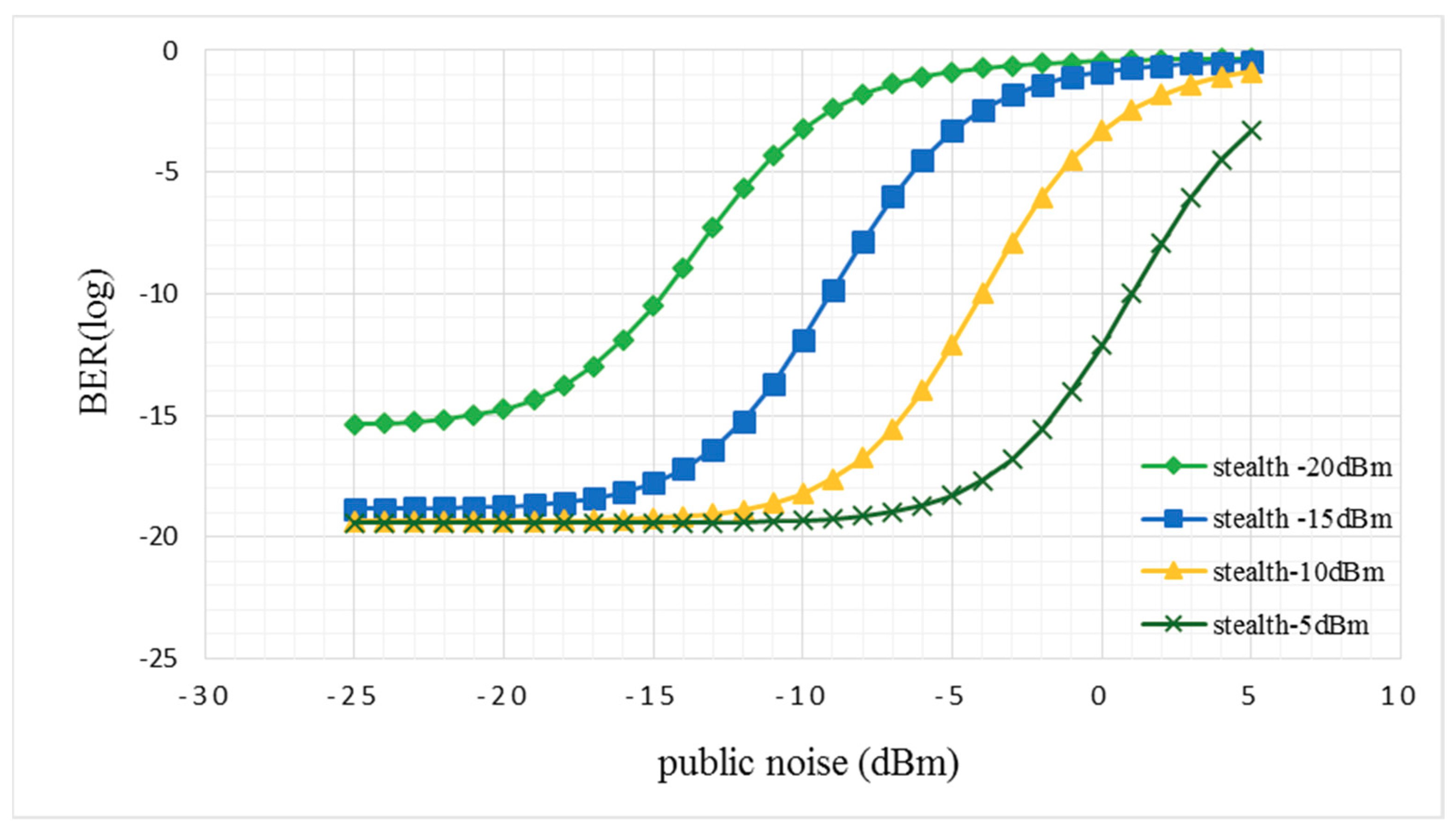
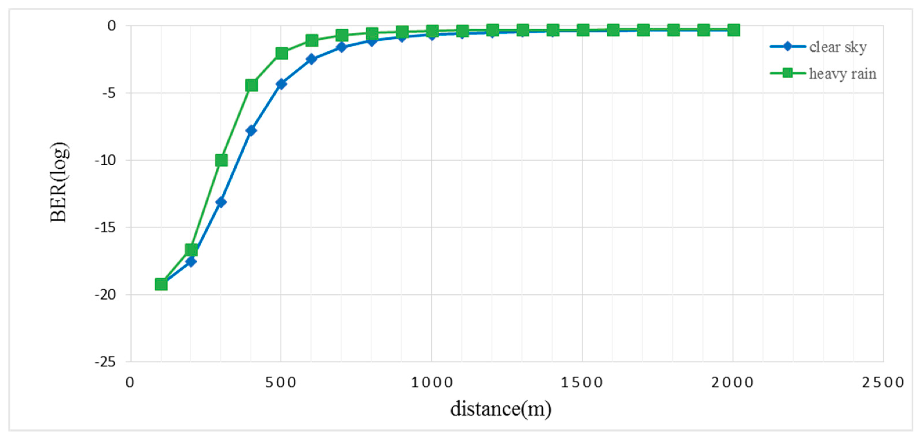
4. System Performance Analysis with Stealth Signal

We assume that the broadband light source of the stealth channel is ideally unpolarized and its spectrum is flat in the bandwidth range [v0 − Δv/2, v0 + Δv/2], where v0 is the central optical frequency and Δv is the optical source bandwidth. From the aforementioned assumptions, we can easily calculate the proposed system performance using Gaussian approximation and u(v), the unit step function, which is expressed as
u ( v ) = { 1 ,   v 0 0 ,   v < 0 .
Let Ck(i) be the ith element of the kth low of the Walsh–Hadamard matrix. The power spectral density (PSD) of the received optical signal can be written as
s ( v ) = P s r Δ v i = 1 N [ b k c k ( i ) + b k c k ¯ ( i ) ] r e c t ( i ) ,
where Psr is the effective power from a single source at the receiver, bk is the data bit of the stealth signal, and N is the length of the codeword. The rect(i) function in Equation (28) is given by
r e c t ( i ) = u [ v v 0 Δ v 2 N ( N + 2 i 2 ) ] u [ v v 0 Δ v 2 N ( N + 2 i ) ] .
The PSD at PD1, PD2, PD3, and PD4 of the stealth receiver during the 1-bit period can be written as follows:
G 1 ( v ) = P s r 2 Δ v i = 1 N b k [ c k ( i ) c k ( i ) ] { r e c t ( i ) } ,
G 2 ( v ) = P s r 2 Δ v i = 1 N b k [ c k ( i ) c k ¯ ( i ) ] { r e c t ( i ) } ,
G 3 ( v ) = P s r 2 Δ v i = 1 N b k [ c k ¯ ( i ) c k ( i ) ] { r e c t ( i ) } ,
G 4 ( v ) = P s r 2 Δ v i = 1 N b k [ c k ¯ ( i ) c k ¯ ( i ) ] { r e c t ( i ) } ,
The coefficient 2 results from using a PBS. Using Equations (5) and (6), the detected photocurrent from the stealth signal at PD1–PD4 can be written as I1, I2, I3, and I4, respectively:
I 1 = R 0 G 1 ( v ) d v = R P s r 2 N [ b k N 2 ] ,
I 2 = R 0 G 2 ( v ) d v = 0 ,
I 3 = R 0 G 3 ( v ) d v = 0 ,
I 4 = R 0 G 4 ( v ) d v = R P s r 2 N [ b k N 2 ] ,
The signal from the stealth channel is given by the difference between the photodiode current outputs:
I 1 I 2 = R 0 G 1 ( v ) d v R 0 G 2 ( v ) d v = R P s r 2 N [ b k N 2 ] ,
I 3 I 4 = R 0 G 3 ( v ) d v R 0 G 4 ( v ) d v = R P s r 2 N [ b k N 2 ] .
After the second differential detection, the signal can be expressed as
I = ( I 1 I 2 ) ( I 3 I 4 ) = { R P s r 2 , b k = 1 0 , b k = 0 .
Noise existing in the proposed SPC-OCDMA system comprises phase-induced intensity noise (PIIN), shot noise, thermal noise, and system noise in the public channel. The frequency band of the public noise is similar to that of the stealth noise. Public noise is difficult to eliminate using normal optical steganography. Using the duplicate process of public signal cancellation at the OCDMA decoder, public noise can be reduced because white noise is unpolarized. Therefore, we use a factor α to denote the decrease in public noise. Using Equation (40), we can obtain the variance of the photocurrent of noise as
i 2 = I s h o t 2 + I P I I N 2 + I t h e r m a l 2 + ( α I p n ) 2 = 2 e I B + 2 I 2 B τ c + 4 K b T n B / R L + ( α I p n ) 2 = 2 e ( R P s r 2 ) B + B R 2 P s r 2 Δ v + 4 K b T n B R L + ( α I p n ) 2
where the notation < > represents the time averaging operator. The index Psr is the effective power from a single source at the receiver, R is the responsibility of PD, B is the noise-equivalent electrical bandwidth of the receiver, τc is the coherence time of the source, e is the electron charge, Kb is Boltzmann’s constant, Tn is the absolute receiver noise temperature, and RL is the receiver load resistor.
Using Equations (40) and (41), the SNR of the stealth signal can be represented as
S N R = ( I b k = 1 I b k = 0 ) 2 I P I I N 2 + I s h o t 2 + I t h e r m a l 2 + ( α I p n ) 2 = ( R P s r 2 ) 2 2 e ( R P s r 2 ) B + B R 2 P s r 2 Δ v + 4 K b T n B R L + ( α I p n ) 2 .
Based on an approximation to the Gaussian distribution, the BER of the SPC-OCDMA system can be expressed as
BER = 1 2 e r f c [ ( S N R 8 ) 1 2 ] ,
where erfc is the complementary error function, which can be expressed as
e r f c = 2 π x exp ( t 2 ) d t .
Thus, we can draw BER-related curves using the aforementioned equations. When the public noise power is −3 dBm, the correlation between the BER and received stealth signal is as shown in Figure 15.
The BER decreases with increasing power of the received stealth signal. A BER of 10−9 is achieved when the received power is −9 dBm.
Figure 16 shows the relationship between the received power of public noise and BER when the received power of the stealth SPC signal is −5, −10, −15, and −20 dBm.
In Figure 16, we observe that the BER decreases when the received public noise power increases. The BER remains constant once the received public noise power has decreased to below a certain value. This is because the received public noise is neglected compared with the shot noise, thermal noise, or PIIN. The larger the power of the public noise, the more confidential the stealth signal. With larger public noise, the stealth signal can be hidden more efficiently, but this causes a higher BER. By contrast, smaller noise power results in superior BERs.
The relative parameters used in the analysis are shown in Table 1.
Next, power attenuation due to the free space optical link is calculated. The performance of the FSO system is affected most strongly by atmospheric turbulence. Although the influence of outer limits is unavoidable, we can control the internal parameters of the FSO system, such as the transmission power of the optical source, laser beam divergence, and receiver aperture area. Opti-System 7.0 is used to calculate the power attenuation. The system parameters are displayed in Table 2.
The power attenuation is observed to be −25 and −30 dB under weather conditions of clear sky and heavy rain, respectively. We discuss the correlation between the BER and transmission distance under the weather conditions of a clear sky and rainy day as shown in Figure 17. The transmission power is set to 20 dBm, which is the maximum value that ensures eye and skin safety.
The BER is found to increase as the transmission distance increases, and it is 2.4 × 10⁻⁹ when the transmission distance is 320 m on a rainy day. When the sky is clear, a BER of 1.62 × 10⁻⁹ is achieved at a transmission distance of 380 m.

5. Conclusions

The present study is preliminary research investigating the probability of applying other types of OCDMA in optical steganography. We have proposed a novel optical steganography transmission technique that conceals SPC-OCDMA signals in a public BPSK channel. A Walsh–Hadamard code is employed as a signature code for assigning a vertically or horizontally linear SOP to each specified wavelength. A CFBG provides considerable dispersion in a small size. The scale of the device is approximately 2000 times smaller compared with a single-mode fiber providing the same dispersion. Herein, the CFBG provides a dispersion of 1600 ps/nm and transforms the stealth signal into a noise-like signal so that it can be buried in the public channel.
The results indicate that the security of the system is enhanced because no one except the intended recipient knows the existence of the stealth signal in either the spectral or time domain. The power of the public noise is proportional to the security of the system and inversely proportional to the performance of the stealth channel. That is, with larger public noise, the stealth signal can be hidden more efficiently but the BER is higher. We propose 1-Gbps stealth transmission with a FSO link.
Furthermore, the pair of CFBGs adds another dimension to the key space of the stealth channel. An eavesdropper needs the correct dispersion compensator to detect the stealth signal. Even if the correct dispersion is obtained by using a tunable dispersion compensator, the eavesdropper cannot recover the data without the corresponding receiver.
The results show that the stealth signal is favorably hidden in the public channel and that our proposed optical steganography system provides high security when the average power of the stealth signal, public signal, and public noise are −5, 0, and −3 dBm, respectively. A range of FSO transmission of up to 380 m can be achieved at a BER of 1.62 × 10⁻⁹ under a clear sky and 320 m at a BER of 2.4 × 10⁻⁹ on a rainy day. Since the system configuration is done in the study, the proposed stealth communication system can furthermore be used to investigate the hiding capacity, distortion measurement and impact on network performance in the future work.

Author Contributions

C.-T.Y. performed the simulations and algorithm analysis, and contributed to manuscript writing. J.-F.H. and W.-Z.Z. contributed in conceiving the experiment and the corresponding data analysis. All authors contributed to writing the paper.

Funding

This research received no external funding.

Acknowledgments

This study was supported in part by the Ministry of Science and Technology MOST 106-2622-E-150-018-CC3 and National Formosa University 106B096.

Conflicts of Interest

The authors declare no conflict of interest.

References

  1. Wu, B.; Shastri, B.J.; Mittal, P.; Tait, A.N.; Prucnal, P.R. Optical Signal Processing and Stealth Transmission for Privacy. IEEE J. Sel. Top. Signal Process. 2015, 9, 1185–1194. [Google Scholar] [CrossRef]
  2. Zeng, G. Quantum Private Communication, 2010 ed.; Springer: New York City, NY, USA, 2010. [Google Scholar]
  3. Fok, M.P.; Prucnal, P.R. All-optical encryption for optical network with interleaved waveband switching modulation. In Proceedings of the Conference on Optical Fiber Communication 2009, San Diego, CA, USA, 22–26 March 2009. [Google Scholar]
  4. Zhen, F.; PU, T.; Wei, Z.H.; Fang, T.; Chen, Y.F.; Zheng, J.L. Optical steganographic transmission of spectral-phase-encoded OCDMA signal over a public DPSK channel. In Proceedings of the 22nd Wireless and Optical Communication Conference 2013, Chongqing, China, 16–18 May 2013. [Google Scholar]
  5. Liang, Y.; Poor, H.V.; Shamai, S. Information theoretic security. Found. Trends Commun. Inf. Theory 2008, 5, 355–580. [Google Scholar] [CrossRef]
  6. Bloch, M.; Barros, J. Physical-Layer Security. From Information Theory to Security Engineering, 1st ed.; Cambridge University Press: Cambridge, UK, 2011. [Google Scholar]
  7. Jamil, T. Steganography: The art of hiding information in plain sight. IEEE Potentials 1999, 18, 10–12. [Google Scholar] [CrossRef]
  8. Ren, K.; Su, H.; Wang, Q. Secret key generation exploiting channel characteristics in wireless communications. IEEE Wirel. Commun. 2011, 18, 6–12. [Google Scholar] [CrossRef]
  9. Khisti, A.; Diggavi, S.N.; Wornell, G.W. Secret-key generation using correlated sources and channels. IEEE Trans. Inf. Theory 2012, 58, 652–670. [Google Scholar] [CrossRef]
  10. Pasolini, G.; Dardari, D. Secret Information of Wireless Multi-Dimensional Gaussian Channels. IEEE Trans. Wirel. Commun. 2015, 14, 3429–3442. [Google Scholar] [CrossRef]
  11. Channalli, S.; Jadhav, A. Steganography an Art of Hiding Data. Int. J. Computer Sci. Eng. 2009, 1, 137–141. [Google Scholar] [CrossRef]
  12. Wu, B.; Narimanov, E. Secure stealth transmission over an existing public fiber-optical network. In Proceedings of the Optical Fiber Communication Conference and the National Fiber Optic Engineers Conference 2006, Anaheim, CA, USA, 5–10 March 2006. [Google Scholar]
  13. Wu, B.; Narimanov, E. A method for secure communications over a public fiber-optical network. Opt. Express 2006, 14, 3738–3751. [Google Scholar] [CrossRef] [PubMed]
  14. Kravtsov, K.; Wu, B.; Glesk, I.; Prucnal, P.R.; Narimanov, E. Stealth Transmission over a WDM Network with Detection Based on an All-Optical Thresholder. In Proceedings of the IEEE Lasers and Electro-Optics Society Annual Meeting Conference Proceedings 2007, Lake Buena Vista, FL, USA, 21–25 October 2007. [Google Scholar]
  15. Wu, B.; Agrawal, A.; Glesk, I.; Narimanov, E.; Etemad, S.; Prucnal, P.R. Steganographic fiber-optic transmission using coherent spectral phase-encoded optical CDMA. In Proceedings of the Conference on Lasers and Electro-Optics 2008, San Jose, CA, USA, 4–9 May 2008. [Google Scholar]
  16. Wang, Z.; Prucnal, P.R. Optical Steganography Over a Public DPSK Channel with Asynchronous Detection. IEEE Photonics Technol. Lett. 2011, 23, 48–50. [Google Scholar] [CrossRef]
  17. Wu, B.; Tait, A.N.; Chang, M.P.; Prucnal, P.R. WDM optical steganography based on amplified spontaneous emission noise. Opt. Lett. 2014, 39, 5925–5928. [Google Scholar] [CrossRef] [PubMed]
  18. Hong, X.; Wang, D.; Xu, L.; He, S. Demonstration of optical steganography transmissionusing temporal phase coded optical signals with spectral notch filtering. Opt. Express 2010, 18, 12415–12420. [Google Scholar] [CrossRef] [PubMed]
  19. Chen, Y.; Wang, R.; Fang, T.; Pu, T.; Xiang, P.; Zhu, H.; Zhang, J. Stealth transmission of temporal phase en/decoded polarization modulated code-shift-keying optical code division multiple access signal over synchronous digital hierarchy network with asynchronous detection. Opt. Eng. 2014, 3, 066103. [Google Scholar] [CrossRef]
  20. Zhu, H.; Wang, R.; Pu, T.; Chen, Y.; Fang, T.; Zheng, J.; Su, G. Complementary coding optical stealth transmission based on amplified spontaneous emission light source. Opt. Express 2014, 22, 28346–28352. [Google Scholar] [CrossRef] [PubMed]
  21. Zhu, H.; Wang, R.; Pu, T.; Fang, T.; Xiang, P.; Zheng, J.; Wu, W. Optical steganography of code-shift-keying OCDMA signal based on incoherent light source. IEEE Photonics J. 2015, 7, 6801607. [Google Scholar] [CrossRef]
  22. Tang, Y.; Li, X.; Gao, T.; Xue, C.; Guo, B.; Yin, S.; Huang, S. Joint routing and wavelength allocation algorithm for stealth and ordinary services in optical transport networks. In Proceedings of the 2017 16th International Conference on Optical Communications and Networks (ICOCN), Wuzhen, China, 7–10 August 2017. [Google Scholar]
  23. Agrawal, G.P. Fiber-Optic Communications Systems, 3th ed.; Wiley, John & Sons: New York, NY, USA, 2002; pp. 38–42. [Google Scholar]
  24. Huang, J.F.; Yang, C.C.; Tseng, S.P. Complementary Walsh–Hadamard coded optical CDMA coder/decoders structured over arrayed-waveguide grating routers. Opt. Commun. 2004, 229, 241–248. [Google Scholar] [CrossRef]
  25. Yen, C.T.; Cheng, H.C.; Chang, Y.T.; Chen, W.B. Performance Analysis of Dual Unipolar/Bipolar Spectral Code in Optical CDMA Systems. J. Appl. Res. Technol. 2013, 11, 235–241. [Google Scholar] [CrossRef]
  26. Wang, C.; Yao, J. Fiber Bragg gratings for microwave photonics subsystems. Opt. Express 2013, 21, 22868–22884. [Google Scholar] [CrossRef]
  27. Fok, M.P.; Prucnal, P.R. Optical Steganography Using Chirped Fiber Bragg Grating. In Proceedings of the Optical Fiber Communication Conference and National Fiber Optic Engineers Conference 2009, San Diego, CA, USA, 22–26 March 2009. [Google Scholar]
  28. Malik, A.; Singh, P. Free Space Optics: Current Applications and Future Challenges. Int. J. Optics 2015, 2015, 1–8. [Google Scholar] [CrossRef]
  29. Sahbudin, R.K.Z.; Kamarulzaman, M.; Hitam, S.; Mokhtar, M.; Anas, S.B.A. Performance of SAC OCDMA-FSO communication systems. Optik 2013, 124, 2868–2870. [Google Scholar] [CrossRef] [Green Version]
Figure 1. Broadening of light along a single-mode fiber.
Applsci 08 01731 g001
Figure 2. Structure of SPC-OCDMA encoder.
Applsci 08 01731 g002
Figure 3. Structure of CFBG providing: (a) positive dispersion; and (b) negative dispersion.
Applsci 08 01731 g003
Figure 4. Structure of FSO system.
Applsci 08 01731 g004
Figure 5. Schematic of optical steganography transmission system.
Applsci 08 01731 g005
Figure 6. Schematic of BPSK public channel.
Applsci 08 01731 g006
Figure 7. Schematic of stealth channel encoder.
Applsci 08 01731 g007
Figure 8. Schematic of stealth channel decoder.
Applsci 08 01731 g008
Figure 9. Spectrum of encoded signal with: (a) SPC code; and (b) SAC code.
Applsci 08 01731 g009
Figure 10. Spectrum of public channel: (a) without stealth signal; (b) with SPC signal; and (c) with SAC signal.
Applsci 08 01731 g010
Figure 11. Waveform of stealth signal in time domain (a) before and (b) after pulse broadening.
Applsci 08 01731 g011
Figure 12. Waveform of public channel in time domain (a) without stealth signal; (b) with stealth signal (1600 ps/nm); and (c) with stealth signal (no dispersion).
Applsci 08 01731 g012
Figure 13. Decoder of SPC stealth signal and demodulator of public signal.
Applsci 08 01731 g013
Figure 14. Public signal in decoder of stealth channel.
Applsci 08 01731 g014
Figure 15. BER versus received stealth signal.
Applsci 08 01731 g015
Figure 16. BER versus received power of public noise.
Applsci 08 01731 g016
Figure 17. BER versus transmission distance.
Applsci 08 01731 g017
Table 1. Relative parameters used in BER analysis.
B: noise-equivalent electrical bandwidth of the receiver.0.5 GHz
Kb: Boltzmann’s constant1.38 × 10−23 J/K
Tn: absolute receiver noise temperature300 K
RL: receiver load resistor.1030
Δv:optical source bandwidth1 THz
R:responsibility of the PD0.8 A/W
α:public noise-suppression factor0.01
Table 2. Relative parameters employed for calculating power attenuation.
L: range1 km
Ω: attenuation3 dB/km (clear sky); 8 dB/km (heavy rain) [29]
Dt: transmitter aperture diameter4 cm
Dr: receiver aperture diameter8 cm
θ: beam divergence1 mrad

