Article

Formation Control Algorithm of Multi-UAV-Based Network Infrastructure

School of Electrical Engineering, Korea University, Seoul 136-713, Korea
*
Author to whom correspondence should be addressed.
Appl. Sci. 2018, 8(10), 1740; https://doi.org/10.3390/app8101740
Submission received: 29 August 2018 / Revised: 13 September 2018 / Accepted: 25 September 2018 / Published: 27 September 2018
(This article belongs to the Special Issue UAV Assisted Wireless Communications)

Abstract

:
This paper addresses the analysis and the deployment of the network infrastructure based on multiple Unmanned Air Vehicles (UAVs). Despite the unprecedented potential to the mobility of the network infrastructure, there has been no effort to establish a mathematical model of the infrastructure and formation control strategies. We model the generic dynamics of the network infrastructure and derive the network throughput of the infrastructure. Through the parametrization of the model, we extract the generic factors of the network protocols and verify our model through the Network Simulator 3 (ns-3). By exploiting our network analysis model, we propose a novel formation control algorithm that determines the location of the UAVs to maximize the efficiency of the network. To achieve the objectives of the infrastructure, we define the formation-shaping effect as forces and elaborately design them using the generic factors. The formation algorithm continuously approaches to the optimized formation of a fleet of UAVs to enhance the overall throughput of the terrestrial devices. Our evaluations show that the algorithm guarantees remarkably higher throughput than the static formations. Through the dynamic transformation of the UAV formation, we believe that the multi-UAV-based network infrastructure could expand the boundary of the existing infrastructure while reducing the network traffic.

1. Introduction

As one of the promising solutions to the increasing wireless network traffic on the ground, a dynamic network infrastructure utilizing a number of Unmanned Air Vehicles (UAVs) was introduced [1,2]. The graphical representation of the network infrastructure is shown in Figure 1. The infrastructure is designed by two components: an ad hoc network among the UAVs, and a wireless access networks per UAV. The UAVs are spread in an area, and they establish an ad hoc wireless network with Ground Control Station (GCS) which is connected with the backbone network. At the same time, each UAV acts as an Access Point (AP) of the access network and connects the terrestrial mobile devices to the backbone network (i.e., Internet). Through the two-folded network architecture, the terrestrial mobile devices nearby the UAVs can connect to the gateway operating at the GCS. The network infrastructure has a number of unique features as follows.
  • Mobility. UAV becomes one of the most versatile devices cooperating with various actuators such as camera [3,4], mechanic arms [5], and even weapons [6]. This trend is originated from the numerous studies in the network of the embedded computing board [7] and the UAV control research domain. While the previous infrastructures statically install a number of the base stations or APs on the ground, the UAVs can act as an AP and instantly deployed at the aerial space to provide the network to the ground. Providing network service by the multiple UAVs is a promising form of the Delay-Tolerant Network (DTN) concept described in RFC 4838 [8]. UAVs and their ad hoc network can act as a bundle layer, and provide functionality of the gateway to deliver the packets on the disrupted environments, such as a disaster area [9], wireless sensor networks [10] or highly congested traffic regions.
  • Scalability. The fact that the UAVs are connected by an ad hoc network suggests the high flexibility of the network coverage. While the existing base stations or terrestrial APs should be plugged by wires that guarantee the connection to the backbone network, the multi-UAV-based network infrastructure can connect a new UAV so as to enlarge the service area of the access network. Also, with the possibility that the pre-installed network infrastructure could be act as a GCS, UAVs can be sparsely deployed in large area while augmenting the network-providing service.
  • Wireless medium extensibility. Due to the immobility of the existing APs and base stations, the majority of the mobile devices share the wireless medium nearby the ground. Although Wireless LAN (WLAN) and cellular network use wired connection except one-hop wireless transmission, increment of the network traffic in a single AP or base station causes drastic decrement of the network throughput of the devices. Since UAVs are flying on the air, the wireless medium of the UAVs cannot be interfered by the channel of the existing networks. By extending the available wireless medium via multiple UAVs, the infrastructure has the potential to enhance the overall network throughput.
Compared to the multi-UAV-based network infrastructure having explicit possibilities, there has been lack of research for improving the system performance of the architecture. The reason for the lack of interest is mainly the doubt about the network efficiency of the infrastructure. Wireless ad hoc network among the UAVs grants the large scalability of network, but the limited range of communication and the throughput decrement of network are noticeable. However, it should be clarified that the multi-UAV-based network infrastructure is a non-replaceable solution in the situation when the previously deployed network infrastructure on the ground is disabled or degraded. To seamlessly provide the network by multiple UAVs in the emergency situations, their formation should be elaborately and instantly controlled in real time. In this paper, we aim to tune up the locations of the UAVs to efficiently provide the network traffic to the terrestrial mobile devices. Optimizing the formation of the UAVs according to the network requirement in a certain area is challengeable since the terrestrial devices are mobile, and tracking all of their exact location is generously hard. Our approach is a real-time feedback control where the UAVs exchange the information of the network (both access network and the ad hoc network) and location status with the neighbors and determine the proper direction to move. To determine the direction, the UAV should consider several aspects: the ad hoc connectivity with nearby UAVs, the extension of the network coverage area, and the traffic management of the ground. We model each concern as a force and each UAV determines a single direction from the sum of the forces. For example, if an UAV establishes excessively many connections with terrestrial devices, the UAV’s network status is reported to the neighbors and the formation is changed to disperse the traffic load of the UAV. However, since the UAV should not lose the ad hoc connection, so the UAV cannot move too far from the others. All of the behaviors are defined as the forces, derived from the information UAVs exchange.
To find the optimal direction of each UAV, we should consider the benefit of the overall network performance on the movement. We firstly analyze the dynamics of the multi-UAV-based network infrastructure on the side of the end-to-end communication between the terrestrial mobile devices and the backbone network. We model the generic phenomenon of the medium access of wireless network and propose the estimation equation of the aggregated throughput among the mobile devices. We verified our model by comparing the analytic result and the simulation result conducted by ns-3, and achieved above 98% accuracy with the simulation. Based on the analytic model, we propose a novel formation control algorithm that consistently enhances the overall network throughput of the multi-UAV-based network infrastructure. Due to the large-scale and extremely high cost feature of the practical experiment, we thoroughly simulated our algorithm and the network environment via ns-3 and shows approximately 41% increase in network throughput.
The contribution of the paper is listed as follows.
  • We designed a network analysis model of the multi-UAV-based network infrastructure. During the derivation of the equations, we suggested a generic mathematical form of the multiple access behavior on the wireless access network. We proved that the generic form fits to the simulated behavior of the wireless access network, and applied the analysis results to the design of the algorithm.
  • We proposed a multi-UAV control algorithm for the multi-UAV-based network infrastructure. The algorithm continuously transforms the formation of a fleet of UAV, while optimizing the network throughput of the infrastructure. Also, we proved that the result of the algorithm is a Nash equilibrium.
  • We implemented a design of the multi-UAV-based network infrastructure, using ns-3. With the simulation tool, we evaluated our algorithm and proved that the algorithm outperforms the regular, static formation of the UAVs.
This paper is organized as follows. Section 2 investigates the former studies in UAV-based network-providing domain, and compares with our study to seize the motivation of this paper. Section 3 addresses the network analysis model of multi-UAV-based network infrastructure and Section 4 proposes a formation control algorithm of the UAVs. Then, we introduce the simulation environment and the evaluation of the model and the algorithm in Section 5. Finally, Section 6 concludes the paper.

2. Related Work

Multi-agent coordination problem has been studied in decades. As the application of the multi-robot system is varied and materialized, recent research focuses on the multi-agent control strategies to enhance the performance on the specific missions. Also, growing numbers of the mobile robots and the devices require more robust and reliable communication schemes on the lossy networks. This section briefly addresses the previous research on mobile networks and the formation control solutions that can be adapted to the multi-UAV management systems, and investigates the research in multi-UAV-based network service provisioning in detail to clarify the contribution of this paper.
Chatzigiannakis et al. [11] studied on the robustness of the mobile ad hoc network where the nodes change their connectivity frequently and unpredictably, and designed a framework for protocol classes to cope with the connection disturbances. In [12], the authors proposed the data collection strategies for a single mobile sink in wireless sensor networks. The authors demonstrated the strategies in several mobility model, and proved the performance of their work. Lee et al. [13] proposed a fast recoverable routing scheme for UAVs using geographic information. The research on the mobile nodes and the sinks is valuable, since most of the nodes in the multi-UAV-based network infrastructure are moving on 2D or 3D spaces. In this paper we focus on the formation control of the multiple UAVs, so we leave the deep consideration on the network protocol as future work.
Inalhan et al. [14] addressed a decentralized coordination problem of multiple aircrafts and proves the optimality of their work by Nash equilibrium. Our algorithm also locates the multiple UAVs in decentralized way, but the specific objective that the access network traffic management of our system reforms the formation to environment-aware one by adding the other equations. In [15], the authors showed an approach to the multi-vehicle formation system in graph rigidity manner and proposes the generic split/rejoin schemes for the stability of the system. This work is similar to a part of our algorithm constructing and maintaining the ad hoc network of multiple UAVs, except for the difference that our algorithm intends to enlarge the network coverage area while considering the traffic concentration. Ref [16] deeply worked on the aerodynamics of the multi-UAV environments and proposes a testbed for aerial control algorithm. While the testbed verifies the actual behavior of the multi-UAV when the formation control algorithm is applied, we evaluate the network performance of the multi-UAV network infrastructure with simulation study when our formation control algorithm is applied. Ref [17] arranged distributed multi-agent coordination systems while categorizing the sub-technologies into optimization, consensus, control, and estimation. Our algorithm consists of (i) the formation control in distributed manner, (ii) the information sharing between the nearby UAVs, (iii) optimality analysis by Nash equilibrium, (iv) estimation by performance modeling.
Calvo et al. [18] proposed a 3D positioning algorithm of the UAVs, considering the environment where the wireless charging stations are deployed. The mathematical models representing the wireless charging is notable, since extending the lifetime of the UAV is one of the crucial challenges in the UAV. However, this paper focuses on the performance improvement of the system using the static, position-optimized wireless charger. Our algorithm targets to the wide-spread mobile users, which move unpredictably.
Bor-Yaliniz et al. [19] worked on the path loss model of the UAV base station in the urban environments. By adopting International Telecommunication Union (ITU) channel model, the research reduces the path loss error from the former models. Adopting the study in [19] could be the promising solution for the environments with high-rise buildings, however, the priori knowledge containing the shape of the building could require the large amount of data, time, and expenditure. Our algorithm implicitly considers the variable path loss, by sharing the current number of connected mobile devices.
References [20,21] designed an UAV deployment problem where the UAV act as a flying base station while connecting to the mobile cellular users or the device-to-device (D2D) communication nodes. There is a difference between our work and this paper since the proposed system in [20] uses a single UAV. However, the approach to the solution which formulates to the disk covering problem [22] is similar to our research, since our algorithm adopts the sphere-shaped network range model.
In [23], the authors proposed the multi-UAV deployment algorithm optimizing the downlink coverage probability and the coverage lifetime. Unlike [20], the solution adopts disk packing problem [24] and derive the optimal position of each UAV. However, disk packing problem results in the blind spot of the network coverage region, which could drop the network performance. Also, optimizing the coverage lifetime might not be notable since the large amount of the power is consumed at the motors in UAV.
Challita et al. [25] designed a multi-UAV network formation game to optimize and stabilize the formation. Also, each UAV’s movements are determined by the virtual force, which let the UAVs maintain the multi-hop connection and avoid the physical collision. Even though the overall concept and approach are similar to our paper, there is a notable difference in terms of the amount of the formation research process. The main contribution of [25] is the expansion of the wireless backhauling area by modifying the node link status, which is addressed in our work called diffusion (See Section 4.4). In addition to the multi-hop network deployment, we applied an additional force to let the formation lean toward to the traffic concentrated area of the ground. In Section 5, we investigated the performance in the cases with and without the additional traffic-aware force.

3. Multi-UAV-Based Network Infrastructure Analysis

This section addresses the mathematical representation of the multi-UAV-based network infrastructure. Our approach is the establishment of the generic expression of the network throughput with variable parameters depending on the network protocol. We firstly present the assumptions and the notations for the analysis of the multi-UAV-based network infrastructure, and then propose the network throughput estimation equation for the mobile devices and the UAVs.

3.1. Assumptions and Notations

We assume that a number of the terrestrial mobile devices are randomly spread at a flat area S. M refers to the set of the mobile devices in S, and m i refers to the ith device where 1 < i | M | . At the same manner, D refers to the set of the UAVs composing the network infrastructure, and d j refers to the jth device where 1 < j | D | . Location of each device is referred to p m i , which is unknown on the side of the UAVs and the network infrastructure. Also, position of each UAV is referred to p d j , and we assume that p d j ( t ) is periodically collected through the navigation devices (e.g., GPS) and shared by the UAVs’ ad hoc channel. Each device could have different amount of the network resource requirement r m i , depending on what application each device uses. We additionally assume that r m i could not exceed the maximum data rate of the data transmission r m a x . Each device is trying to access the Internet by scanning the nearby AP providers (UAVs) and connecting to the one of them.
For mobile devices to connect the Internet, they scan the APs around the locations. We refer the maximum range of the AP connection provided by the UAVs to the R A P . We assume that the mobile devices select an AP (UAV) broadcasting the beacon signal with the best SINR, which can be expressed to
AP ( m i ) = arg max d j s m i S I N R ( m i , d j )
where s m i refers to the set of the UAVs scanned by m i and S I N R ( a , b ) refers to the SINR of the a beacon signal from the device b. The assumption is valid since the existing AP selection mechanisms commonly shape the decision metric according to the received signal strength or SINR [26,27]. On the UAV’s side, a set of connected mobile devices are referred to C ( d j ) , which can be obtained by
C ( d j ) = { i | AP ( m i ) = d j } .
We assume that the channel used by AP network of the UAVs and the channel used by ad hoc network are completely isolated, which means that there is no channel interference between the AP and ad hoc network. The assumption also can be accomplished by using the different frequency band (e.g., 2.4 GHz for AP and 5.0 GHz for ad hoc). The assumption is not only for the simplicity of the modeling, but the expected performance of the network infrastructure. If APs and ad hoc use the same channel, the medium is shared by the nearby UAVs as well as the devices connected in the same AP. Furthermore, since an expected network resource requirement of the ad hoc connection is the sum of resource requirement of the AP connections, AP network performance might be significantly lowered by the contention with the ad hoc connections.
Also, we assume that the ad hoc network routing protocol results in the optimized routing path while the UAVs are changing their locations. Since the network infrastructure specifies the GCS as a sync node, the UAVs spread directionally or omni-directionally around the GCS. We refer the number of connected UAVs with a certain UAV d j in a single hop to N d j , which can be calculated to
N d j = | { d k | d i s t ( d k , d j ) < R a d h o c } |
where R a d h o c refers to the maximum range of the one-hop communication of ad hoc network.

3.2. Wireless Access Network

This section addresses a generic form of the wireless access network model mathematically. Due to the resource limitation of the wireless medium and the randomized media access of the wireless devices, the network performance decreases when the number of the devices increase. As each UAV works as an AP, the UAVs might connect to the randomly spread users, which leads the large deviation of the number of connections between the UAVs. Some UAVs with relatively large number of the connections could suffer from the significant drop of the network performance, while some UAVs with relatively small number of the connections might waste the network resource. To elaborately distribute the network traffic to the UAVs, the mathematical model of the wireless access network and the numeric factors that affects the formation control should be designed. Also, there are valuable approaches to alleviate the risk of the packet collision such as Carrier Sense Multiple Access with Collision Detection (CSMA/CD) [28], variations of ALOHA protocol [29], and Orthogonal Frequency-Division Multiple Access (OFDMA) [30]. To give the generic view and enhance the flexibility to the model, we propose a mathematical expression of the aggregated throughput with a protocol-dependent parameter, which could be estimated by comparing the analytic solution and the simulated solution.
First, we define a network capacity R, which refers to the maximum data rate of a connection where only one mobile device is connected to a UAV, without any electrical interference and obstacle. Based on the R, the ratio of the network throughput degradation is exponentially increased as the number of mobile devices in the same network ( C ( d j ) ) increases, due to the increased possibility of the collision. In a certain point of the time, the possibility of the collision when n devices are in the same medium is
2 n n 1 2 n 1 .
However, there are some previous studies allowing the concurrent transmissions by sub-channels [30] or code division [31], so the variable n could be divided into the approximated amount of the concurrent transmissions. Also, to reduce the collision probability, the mechanism that randomly backs off a number of time slots and detect the medium [28,32] and its variations [33,34,35] were studied. Considering these improvements, the throughput degradation ratio, D ( n ) can be expressed by augmenting Equation (4) to
D ( n ) = 1 1 β 2 n α n α 1 2 n α 1
where α and β are named to concurrent transmission availability and congestion relaxation degree of the protocol respectively, and n = | C ( d j ) | . As α or β increase, the degradation of the throughput decreases. Note that α and β do not represents the physical property or performance of the protocols, for instance, α = 10 does not suppose that an AP holds exactly 10 transmissions at maximum. Our generic model involves the common behavior of the wireless network and the parameters representing the evolution of the communication techniques. The verification of Equation (5) shows in Section 5.4. Since the objective of the paper is the improvement of the throughput of the infrastructure, we estimate α and β of the WLAN protocol by the simulation and reflect to the formation algorithm.
By the assumption stated in Section 3.1, the devices could require different amount of the network resource. When the multiple devices try to access the same wireless channel, the actual amount of the network resource provided by the UAV is proportionate to the required resource. Reflecting the congestion of the medium expressed in Equation (5), the provided network capacity r m i can be expressed to
r m i = max R × r m i k C i r m k , r m i × D ( | C i | )
where C i refers to the C ( d A P ( m i ) ) . The Equation (6) grants an insight of the importance of the congestion control and the direction of the throughput optimization. Full provision of the UAVs’ network capacity meets the original purpose of the network infrastructure, but the congestion occurred by the excessive connections could drop the performance of the access network. Our formation control algorithm leverages the mobility of the UAVs to mitigate the congestion of WLAN network and enhance the aggregated throughput of the network infrastructure. Finally, the network throughput carried by the UAV T d j is calculated to
T d j = k C i r m k .
Note that T d j R × D ( | C i | ) since the total network resource amount for m i C i could not be equal to the R.

3.3. Ad Hoc Network

The UAVs in the network infrastructure should forward the data from the mobile devices to the Internet gateway (uplink) and from the gateway to the mobile devices (downlink). In the multi-hop communication, the same phenomenon introduced in Section 3.2 should be considered in chain. For example, if the UAV 0 in Figure 2 tries to transmit the data to UAV 2, the UAV should contend with the UAV 1 to use the medium. Also, the contention between the UAV 2 and the UAV 3 affects the throughput of the data received from the UAV 0 or the UAV 1. If we let P d j refer to the set of the UAVs included in the routing path to the GCS (e.g., P A = { C , E } in Figure 2), the actual throughput (received data rate of the GCS) T d j becomes
T d j = T d j m P d j D ( N d m ) .
The analysis suggests that the expected routing path of the UAVs should be given to calculate the network throughput of the infrastructure. Our formation control algorithm estimates the expected routing path and the congestion of the wireless medium by the location information of the UAVs, collected periodically on the basis of the assumption stated in Section 3.1. Also, on the layer of ad hoc network, increasing N d j and the hop count decreases the network throughput of the infrastructure.
Assuming that all UAVs are in the ad hoc network, the overall network performance of the multi-UAV-based network infrastructure N is calculated to
N ( D , M ) = d j D T d j .
As shown in Equation (9), optimizing D whose object function is a non-linear | D | × | M | dimension function is a remarkably complicated and might take high cost of time to estimate while following the changes of M. To cope with the unexpected change of the M, we periodically determine the flying direction of the UAVs to enhance the network throughput of the infrastructure in our formation control algorithm. The observations of the analysis are considered on the algorithm.

4. Formation Control Algorithm

The formation of the UAVs has a profound effect on the performance in the multi-UAV-based network infrastructure. Based on the design of the infrastructure stated in Section 3.1 and the model described in Section 3.2 and Section 3.3, we list the objectives of the UAVs’ formation as follows.
  • All UAVs should maintain the ad hoc connectivity between each other.
  • Congestions on the access networks and the ad hoc network should be reduced.
  • The infrastructure should connect the mobile devices as many as possible.
  • UAVs should not be redundantly deployed; Formation should use minimal UAVs to maximize the network performance.
  • Formation should be changed in response to the change of M.
To achieve the multiple objectives in real time, we designed a novel feedback-based formation control algorithm of the network infrastructure. For each UAV in a specific start location, the algorithm determines the flying direction of each UAV in a short period, according to the periodically received information from the UAV itself and the neighbors. Our approach is to define the forces designed to fulfill the requirements of the network infrastructure and applied to the UAVs to change the direction of each [36]. By the vector sum of the forces, each UAV flies to the specific direction with a limited speed as shown in Figure 3.
The periodically received information of the UAV used by the algorithm includes
  • The position of the gateway, p 0
  • The position of the UAV, p
  • The positions of the nearby UAVs, p i
  • The positions of the next hop UAVs, p j
  • The number of the connected devices of the UAV, n
  • The numbers of the connected devices of the nearby UAVs n i
Which are collectable (We use the abbreviated notations in those variables for readability). The subsections listed in the below describe the forces applied to the UAVs and the control mechanism of our algorithm.

4.1. Ad Hoc Connectivity Force

The loss of the ad hoc connection for a UAV could lead to a serious tragedy, which is not only the drastic reduction of the performance but the loss of the control for the UAV. In our formation control design, ad hoc connectivity force has the most dominant magnitude if the connections come to weaken, mostly by the path loss due to the distance. We call neighbors that could be the next hop of a certain UAV in ad hoc network. With respect to the Euclidian distance to the next hop nodes, ad hoc connectivity force F a d h o c is expressed to
F a d h o c = H max exp ( | p j p | A ) 1 , 0 ( p j p )
where H is referred to the set of the next hop nodes and A is named to the ad hoc connectivity force threshold. Designing F a d h o c as the distance to the next hop nodes is valid since the UAVs are flying above the flat area in the assumption stated in Section 3.1. F a d h o c is applied to the UAV only the UAV is far enough to the next hop nodes to jeopardize the ad hoc connectivity. The threshold A is determined with respect to the ad hoc communication range R a d h o c . In our implementation, we observed that the performance is maximized when A = 0.8 R a d h o c .

4.2. Neighbor Distribution Force

If UAVs are too closed in a certain area, their network capacity could be redundant and the wireless medium could be overlapped. Neighbor distribution force is applied to spread out the clustered UAVs and expand the overall network coverage space of the infrastructure. In the same manner introduced in Section 4.2, neighbor distribution force F d i s t r is expressed to
F d i s t r = E min ln | p p i | A , 0 ( p i p ) .
where E is referred to the set of the nearby UAVs, unlike F a d h o c .
In the UAV-to-UAV position control, F a d h o c and F d i s t r applies the exactly opposite direction of force to the UAV. However, the difference in the set of the vectors (H and E) let the UAVs to shape the formation properly. For example, although the neighbor is distributed enough and the ad hoc connectivity is kept, the network infrastructure could not be accomplished if any UAV cannot connect to the GCS. Since H could include the GCS, the UAVs can safely forward the data between the backbone network and their connected devices.

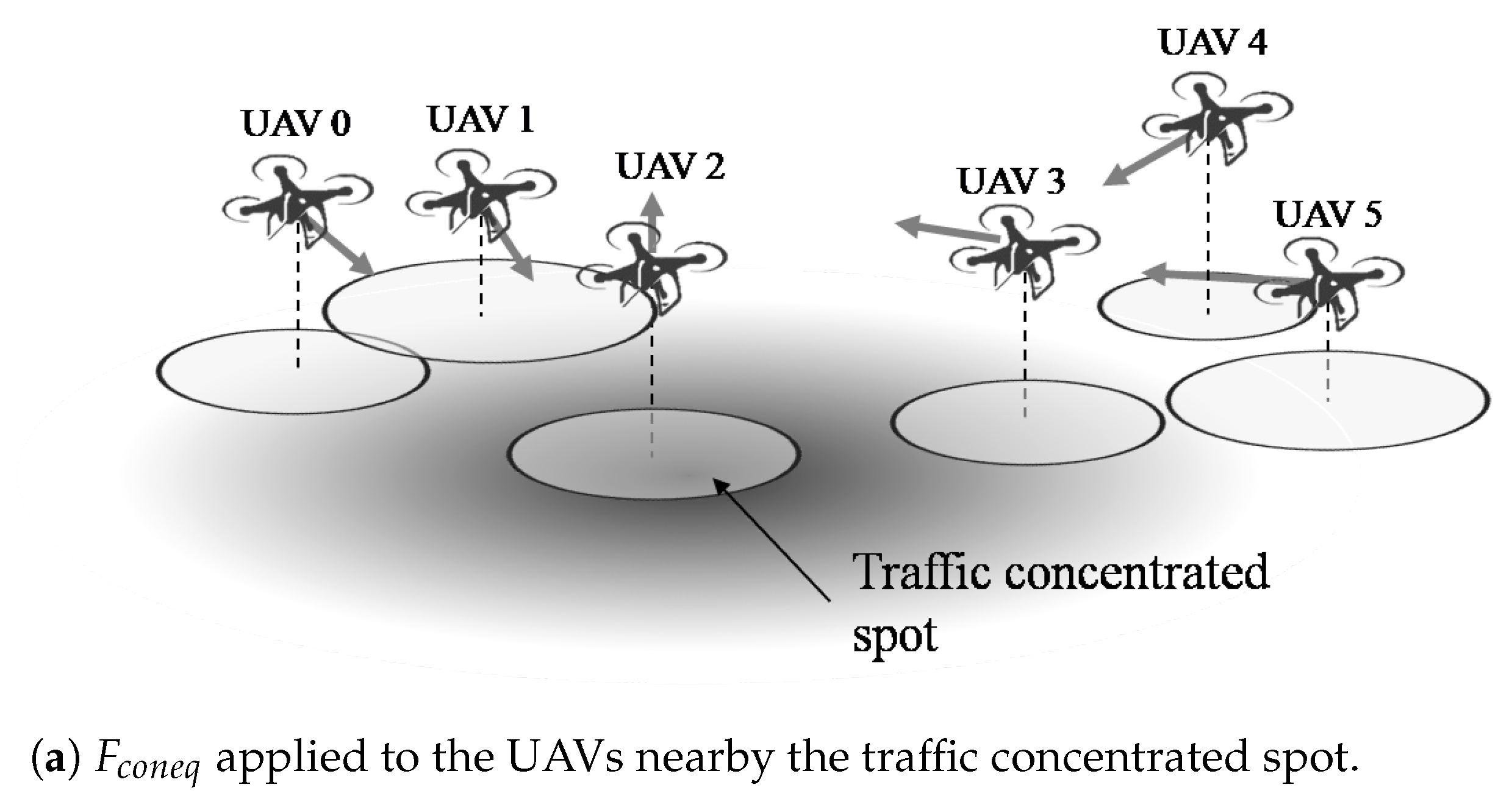
4.3. Congestion Equalization Force

F a d h o c and F d i s t r form the UAV fleet regularly; at the same altitude, and the same distance between the nodes. Although these two forces let UAVs be spread while maintaining the connection with the gateway, there is no concern about the traffic management of the end devices, which could make some UAVs redundant or cause the traffic concentration. In particular, variability of the altitude of the AP is one of the most essential advantages of the UAV-based network infrastructure, since the altitude determines the communication area projected at the ground (Equation (1)). As shown in Equation (5), excessive increment on the number of the connections in a single UAV degrades the network performance of the infrastructure. Under the influence of the aforementioned background forces, congestion equalization force is designed to let UAVs subdivide the traffic concentrated spots to equalize the congestion of the UAVs. We apply the force with direction to the + z axis for the relatively more congested UAVs to explicitly narrow the coverage space and reduce the connections. Meanwhile, the relatively less congested UAVs are applied the force with the direction to the z axis and the direction toward the highly congested UAVs. Through this equalization force, the less congested UAVs take over a part of the devices which are excessively connected to another UAV. Also, to progressively seek the network resource requirement on the ground, relatively low congestion UAVs push the relatively high congestion UAVs until the expected congestion comes to the equilibrium. The equation of the congestion equalization force F c o n e q can be expressed to
F c o n e q = 1 β E n n i | n n i | exp ( | n n i | ) ( p p i ) + h i
where
h i = 0 0 1 β exp ( | n n i | ) .
Congestion relaxation degree β determines the weight of the F c o n e q , since the congestion could be relaxed by the protocol and then the support of other UAVs is less needed. Figure 4a,b show an example of our F c o n e q design graphically. For better readability, we use the terms attractive and repulsive forces for every F c o n e q applied. Since UAV 2 located in the center of the traffic concentrated area, the altitude gets higher and the position is changed by the repulsive force by the nearby UAVs. On the case of UAV 3, the repulsive force is applied by UAV 4 and 5, and the attractive force is applied by UAV 2. By the sum of the forces, UAV 3 is dominantly powered by the repulsive force toward the center of the traffic concentrated area. UAV 0, 1, 4, and 5 receive the same direction of the power, but also receive the downward power by Equation (13). UAV 3 has more congestion than UAV 4 and UAV 5, and less congestion than UAV 2. As a result, the altitude change of UAV 3 is less than the other UAVs. One of the examples of the result formation effected by F c o n e q is shown in Figure 4b. Note that the excessive clustering among the UAVs by F c o n e q is prevented by F d i s t r , addressed in Section 4.2. On the basis of the formation maintenance forces F d i s t r and F a d h o c , F c o n e q reforms the formation to be more traffic-aware.

4.4. Feedback-Based Control

Through the forces defined in Section 4.1, Section 4.2 and Section 4.3, we designed a novel feedback-based UAV formation control algorithm as Algorithm 1. In addition to the summation of the forces, we added the ad hoc network expansion procedure named diffusion from line 7 to 13. At the first step, all UAVs are directly connected to the GCS with a single hop to sustain the connectivity of the network infrastructure. At the state of the line 7, a UAV could guarantee the route path to the GCS by one of its neighbors in E. Then, the UAV cuts the farthest next hop connection and declares the diffusion to the nearest neighbor, to prevent the loss of the GCS connections of all UAVs. NeighborDiffused() function returns true if the UAV is informed the diffusion of another UAV.
Algorithm 1 Formation control algorithm
1:
Collect p 0
2:
Initialize H = { p 0 } , E = ϕ
3:
while True do
4:
    Refresh p , p i , n , n i , E
5:
     d ( 0 , 0 , 0 )
6:
     C a l c u l a t e F a d h o c , F d i s t r , and F c o n e q
7:
    if F a d h o c 0 a n d | F d i s t r | + | F c o n e q | > | F a d h o c | then
8:
        if !NeighborDiffused() then
9:
            R e m o v e arg max j | p p j | from H
10:
            H H E
11:
           Recalculate F a d h o c
12:
           Inform the diffusion to the nearest neighbor
13:
        end if
14:
    end if
15:
     d F a d h o c + F d i s t r + F c o n e q
16:
    Set direction to d | d |
17:
end while
On the congestion equalization, the force applied by a few differences of the connection counts could lead to the oscillation of the UAV. Since the frequent AP change of the mobile device could lead to the degradation of the performance, we utilize the concurrent transmission availability α as a threshold of the F c o n e q summation. The larger value of the α grants more sustainability of the UAV’s formation.

4.5. Algorithm Analysis

To validate our formation control algorithm, we prove that the output of the algorithm is a Nash equilibrium [37]. Let S i = v t d i / | d i | is the movement for the UAV d i in a time period t with the speed v, then S = S 1 × S 2 × × S | D | is the set of strategy profiles. Since the objective of the algorithm is the enhancement of the network performance, payoff function could be expressed by the overall network throughput difference of the infrastructure such as
f ( x ) = Δ N ( Δ D , Δ M )
where x refers to a certain direction (unit vector) of the UAV at t. On the circumstances that all x = d / | d | is given, let x i satisfies f ( x i , x i ) > f ( x i , x i ) . If x i causes the loss of ad hoc connection of a UAV, f ( x i , x i ) f ( x i , x i ) due to Equation (9) where T d j 0 . Otherwise, if x i causes the changes of the connected devices, there are total 4 cases as follows.
  • Decrement of the C ( d j ) leads to the decrement of the T d j except the case of the excessive C ( D j ) , which is already reflected by x i in Equation (13). It leads to the decrement of the T d j by Equation (8).
  • Increment of the C ( d j ) leads to the decrement of the D except the case of the redundant R, which is already reflected by x i in Equation (12).
  • Bringing already connected devices from other UAVs leads to the decrement of the D of i and the redundant R of the other UAVs, except the case of the congestion equalizing addressed in Section 4.3, which is already reflected by x i .
  • Yielding already connected devices to other UAVs leads to the redundant R of i and the increment of the D of the other UAVs, except the case of the congestion equalizing addressed in Section 4.3, which is already reflected by x i .
Otherwise, x i induces the delay of the network coverage expansion and the reduction of the possibility to discover a new connection, while x i reflects the best possible point by Equation (11). In conclusion, the above statement is contradictory to the assumption that there is a x i which satisfies f ( x i , x i ) > f ( x i , x i ) . Hence, the algorithm is proved that the output S is a Nash equilibrium.

5. System Evaluation

We used our simulation tool for two objectives: verification of the analytic model expressed in Section 3, and evaluation of the formation control algorithm proposed in Section 4. In this section, we address the simulation design of the multi-UAV-based network infrastructure. We implemented the simulation using Python language and ns-3 library. Figure 5 overviews the simulation design and the ns-3 internal functions used, and the following subsections describe the design of the simulation in detail.

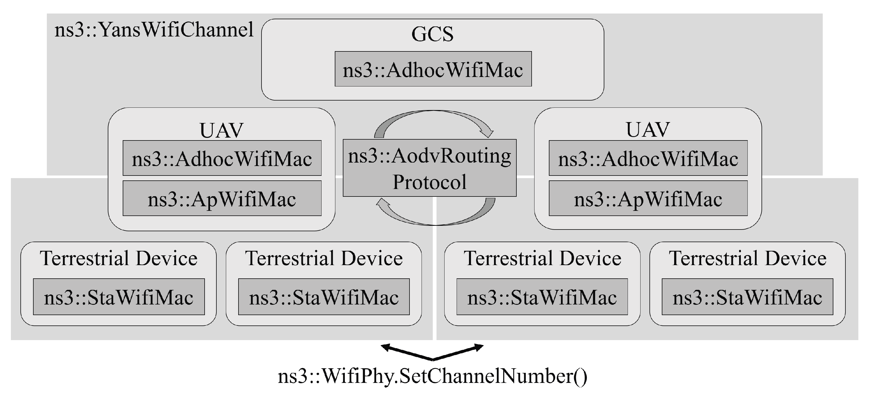
5.1. PHY and MAC Device Installation

We employed IEEE 802.11 Wi-Fi Physical Layer (PHY) and MAC model. The AP network has 3 channels (Channel number 1, 6, and 11) to select, for minimizing the medium overlap between the adjacent APs. The ad hoc network uses a single channel reflecting the native communication pattern. Ad hoc network channel and the AP channels are distinctly instantiated without any expected interference, to follow the assumption in Section 3.1. Mobile nodes can change the AP connection safely since all APs use the same channel. Unlike the mobile nodes and GCS have one network device for the station and the ad hoc respectively, UAVs have two network devices for the AP and the ad hoc. The UAVs broadcast a beacon signal per second.

5.2. Network and Transport Protocol

There are | D | + 1 subnetworks, one for ad hoc and | D | for APs. Internet Protocol (IP) addresses for the UAVs and the GCS is pre-assigned at the simulation environment install step. For the terrestrial nodes, IP addresses could be changed dynamically, no IP address is assigned in advance. However, it should be noted that ns-3 does not support automated Wi-Fi selection scheme internally. Mobile nodes cannot change the IP address dynamically by scanning the around APs and change the connection. To resolve the phenomenon, we explicitly probed the APs nearby each mobile node and reassigned the IP address in a certain period. In our implementation, the AP scan occurs per 3 s. Also, we employed Ad hoc On-demand Distance Vector (AODV) routing protocol [38] for the ad hoc network. In our previous work, we found that AODV outputs the best performance of the ns-3 supporting routing protocols for the ad hoc networking in terms of the connectivity and the data rate. Finally, to focus on the PHY to the Network layer performance, we employed User Datagram Protocol (UDP) protocol to reduce the transport layer overhead of the simulation.

5.3. Application Scenario

We employed a simple application model that consistently requests the fixed amount of data rate, which is referred to r m i in this paper. Following the objective of the UAV-based network infrastructure, all the terrestrial devices try to connect to the backbone network by the gateway (i.e., GCS) and one of the UAVs. We installed PacketSink at the gateway and measured the overall throughput of the network.

5.4. D Model Verification

By using the simulation addressed in previous subsections, we verify the network throughput model of multi-UAV-based network infrastructure. At first, we observe the dynamics of D , which is the basis of the network throughput models addressed in this paper. To estimate α , β of D ( n ) , we run the simulation with a single UAV and the varying number of the terrestrial devices | M | , and measure the network throughput. The devices are spread in the 20 m × 20 m area on the ground, and the GCS is located at the center of the ground, which is set to the origin. A single UAV is deployed at ( 0 , 5 , 5 ) , and the devices preliminary receive the IP address included at the subset of the UAV. GCS sends data to all of the devices in 1000 Kbps data rate equivalently, and the average network throughput is calculated by the average received data rate among the devices. Each case is simulated by 10 times with 300 s runtime, and | M | varies to 1 | M | 60 . Figure 6 shows the simulation result and the analytic solution where α = 9.8170 and β = 1.2044 .
When applying Equation (5), we observed that D ( n ) > 1 where n < α . The phenomenon is due to the α , since the equation calculates D in a case that a single connection has more sub-channels to occupy. However, the required network resource is limited to r m i , so we cut out these values into the maximum ratio 1. With the aforementioned α , β values, the analytic solution achieves above 98% accuracy with the simulation. If we increase the repetition count, the fluctuation of the measured throughput in the range of 20 | M | 25 might be reduced. From the observation, we concluded that our throughput model forecasts the network throughput of the multi-UAV-based network infrastructure with acceptable accuracy, by fitting α and β with respect to the desired network protocol.
To verify our formation control algorithm, we expanded the map size to 500 M × 500 M, and increase the number of devices to 100. The GCS is located at the center of the map and the UAVs are initially spread around the GCS with the altitude of 60 M. The parameters α , β are applied to the 9.8170 and 1.2044 respectively, and the directions of the UAVs are calculated per 0.5 s. The terrestrial users are deployed with two-dimensional Gaussian distribution, centering a random location ( x , y ) on the map. We observed the result of the algorithm working on 15 UAVs and graphically represented in Figure 7.
In Figure 7a,b, grey circles represent the communication range of the AP ( R A P ) on the ground, and the number on the icon of the UAVs are the identifiers. Also, both figures show the stabilized (no oscillation by the forces) formation of the UAVs after 30 s. Even though the distribution of the UAVs in Figure 7a are regular, the actual connections to the terrestrial devices are not equalized (see Figure 7c,e) since the distribution of the devices are focused at nearby of UAV 3 and 4. UAV 10, 12 and 13 does not have any connection to the devices, which results in the redundant usage of the UAVs. On the other hand, the formation with F c o n e q shown in Figure 7b, the formation of UAVs is reformed toward the cluster of the devices, while each UAV providing the access network to at least 5 devices. Deploying UAV 2, 3, 4, and 6 nearby the cluster of the devices could more reduce the traffic concentration of the infrastructure. Also, F c o n e q dynamically adjusts the altitude of the UAVs to efficiently equalize the congestion as shown in Figure 7d. Through the observation, we verified that the algorithm adaptively controls the formation of the UAVs to reduce the network traffic of the multi-UAV based network infrastructure with various deployment cases of the devices.
To observe the dynamics of the formation algorithm, we performed numerical evaluation while varying the number of the terrestrial devices | M | from 100 to 300, as shown in Figure 8. For each | M | value, we performed the formation algorithm 50 times for the case with and without F c o n e q and recorded | C i | after the formation is stabilized. Successful coverage ratio in Figure 8a is calculated by | C i | / | M | , which results in the ratio of the connected mobile devices and the total devices. The case with F c o n e q outperforms the case without F c o n e q independent to | M | , since F c o n e q not only equalizes the WLAN congestion but pushes the edge-located UAVs out to search the unconnected devices. Also, the case with F c o n e q and 15 UAVs cover greater number of the devices than the case without F c o n e q and 20 UAVs, which means that F c o n e q can result the better coverage ratio with fewer UAVs. Figure 8b shows the standard deviation of | C i | . As shown at the example of Figure 7, standard deviation of the case with F c o n e q is much less than the case without F c o n e q . Also, as | M | increases, standard deviation of the case without F c o n e q increases, but the case with F c o n e q does not change since | C i | keeps equalized. Estimated throughput refers to the average of the devices’ throughput calculated by Equation (5) with | C i | , assuming that each device sends data packet with rate 1 M b . Due to the network capacity of the AP and the congestion, estimated throughput has no choice but to decrease as | M | increases. However, as previously verified in Figure 6, decreasing the number of | C i | can reduce the loss of the throughput. The case with F c o n e q and 20 UAVs results in the best throughput on the evaluation, while the difference grows as | M | increases. To provide the better quality of the devices, increasing the number of the UAVs could be the easiest way, but it might not bring the meaningful changes in terms of the coverage (Figure 8a) or the standard deviation (Figure 8b). Dynamically adjusting the number of the UAVs can be the promising strategy to improve the UAV-based network infrastructure.

5.5. Network Performance Simulation

We also simulate the network throughput of the multi-UAV-based network infrastructure using the formation control algorithm. Since there is no existing method considering the formation of the UAVs of the network infrastructure, we compare the two cases where one applies F c o n e q and the other does not apply F c o n e q . The comparison is valid since the formation without F c o n e q shows hexagonally patterned deployment of the UAVs, which is widely used in the placement of the wireless network infrastructure [39]. We firstly deployed the mobile devices with a cluster centered at ( 100 , 100 ) in the map, and let the devices move in the direction ( 1 / 2 , 1 / 2 ) , as shown in Figure 9a. The devices start to move at 50 s from the start of the simulation, and stop to move at 70 s. The devices send packets to the GCS with 100 Kbps after the 20 s from the start of the simulation, and the network throughput is measured per second. Figure 9b shows the changes of the network throughput with respect to the time for two cases.
The simulation evaluates two aspects: the network throughput enhancement and the time-variant flexibility of the formation shaped by the algorithm. Figure 9b shows that our formation control algorithm with F c o n e q outperforms the network throughput at the whole time, except for the short intervals such as 25 to 26 s and 72 to 73 s. The reason of the temporal drop was the large number of the AP connection changes in a short period due to the change of the formation, which leaded to the update of the routing path. After the short interval, the network throughput is recovered and outperforms the case without F c o n e q again. The simulation verifies that the algorithm recognizes the dynamic location changes of the mobile devices by the exchange of the neighbors’ network status, and changes the formation of the UAVs to enhance the network throughput in real time. By the calculation of the average network throughput of 10 repetitions, the case with F c o n e q results in 41.2% better performance than the case without F c o n e q on average. Since the case without F c o n e q does not change the formation of the UAVs in time, the case is the representation of the deployment of the location-fixed network infrastructure, and then difference to the case with F c o n e q is the profit obtained by the proposed algorithm addressed in Section 4. Through the simulation, we verified that the proposed formation control algorithm enhances the network throughput of the multi-UAV-based network infrastructure on the fluctuation of the terrestrial network requirement.

6. Conclusions

In this paper, we study the design of the multi-UAV-based network infrastructure and propose a formation control algorithm. Based on the necessity of an instant and extensible network infrastructure, our algorithm dynamically transforms the network coverage of the infrastructure and leads to the enhancement of throughput. To grant the flexibility of the algorithm, we address the generic network model of the multi-UAV-based network infrastructure and derive protocol-specific parameters that could be applied to the algorithm. In addition, we have several research directions for future work:
  • Network protocol. Formation algorithm equalizes the congestion by moving the UAVs, which could possibly incur handover between the APs more frequently. Handover procedures might decrease the throughput of the infrastructure, so the protocol that supports fast recovery from the connection change is needed. Also, we observed that the IPv6 Routing Protocol for low-power lossy networks (RPL) [40] is a promising routing scheme to adapt to the multi-UAV-based network infrastructure. The network model utilizing RPL in the network infrastructure should be analyzed and the pros and cons should be addressed.
  • Terrain. This paper assumes that the ground is flat. Although the altitudes of the UAVs are sufficiently high to ignore some elevation of the terrain, some environments with high elevations or buildings could affect the formation of the UAVs. To manage the WLAN network traffic, z axis change could not be enough to approach optimal formation, which needs to improve our formation algorithm.
  • Evaluation. We evaluate our formation control algorithm by ns-3. Even though ns-3 is one of the well-known network simulation tool and continually revised for improvements, it could suffer from precision issues due to lack of real-world projection. To evaluate our formation control algorithm on a more practical testbed, a dataset extracted from real-world environments [41] could be desirable.
We believe that our algorithm contributes to the increased availability of the multi-UAV-based network infrastructure in various situations, such as rescue or surveillance missions. Also, we hope that our novel approach to progressively controlling the formation of the mobile network nodes will present new possibilities for flexible network design.

Author Contributions

Conceptualization, S.P. and K.K.; Methodology, S.P.; Software, S.P.; Validation, K.K. and H.K. (Hyunsoon Kim); Writing—Original Draft Preparation, S.P.; Writing—Review & Editing, K.K., K.K. and H.K. (Hwangnam Kim); Supervision, H.K. (Hwangnam Kim).

Funding

This research was supported by Nano UAV Intelligence Systems Research Laboratory at Kwangwoon University, originally funded by Defense Acquisition Program Administration (DAPA) and Agency for Defense Development (ADD).

Conflicts of Interest

The authors declare no conflict of interest.

References

  1. Chung, A.Y.; Jung, J.; Kim, K.; Lee, H.K.; Lee, J.; Lee, S.K.; Yoo, S.; Kim, H. Poster: Swarming Drones Can Connect You to the Network. In Proceedings of the 13th Annual International Conference on Mobile Systems, Applications, and Services, Florence, Italy, 18–22 May 2015; ACM: New York, NY, USA; pp. 477–477. [Google Scholar]
  2. Yoo, S.; Kim, K.; Jung, J.; Chung, A.Y.; Lee, J.; Lee, S.K.; Lee, H.K.; Kim, H. Poster: A multi-drone platform for empowering drones’ teamwork. In Proceedings of the 21st Annual International Conference on Mobile Computing and Networking, Paris, France, 7–11 September 2015; ACM: New York, NY, USA; pp. 275–277. [Google Scholar]
  3. Lee, J.N.; Kwak, K.C. A trends analysis of image processing in unmanned aerial vehicle. Int. J. Comput. Inform. Sci. Eng. 2014, 8, 2–5. [Google Scholar]
  4. Jung, J.; Yoo, S.; La, W.; Lee, D.; Bae, M.; Kim, H. AVSS: Airborne Video Surveillance System. Sensors 2018, 18, 1939. [Google Scholar] [CrossRef] [PubMed]
  5. Lippiello, V.; Ruggiero, F. Exploiting redundancy in Cartesian impedance control of UAVs equipped with a robotic arm. In Proceedings of the 2012 IEEE/RSJ International Conference on Intelligent Robots and Systems (IROS), Vilamoura, Portugal, 7–12 October 2012; pp. 3768–3773. [Google Scholar]
  6. Gregory, D. From a view to a kill: Drones and late modern war. Theor. Cult. Soc. 2011, 28, 188–215. [Google Scholar] [CrossRef]
  7. Eshwarappa Dandur, V.; Weng, N. Networked Embedded System Security: Technologies, Analysis and Implementation. Recent Adv. Commun. Netw. Technol. 2016, 5, 90–107. [Google Scholar] [CrossRef]
  8. Cerf, V.; Burleigh, S.; Hooke, A.; Torgerson, L.; Durst, R.; Scott, K.; Fall, K.; Weiss, H. Rfc 4838: Delaytolerant Network Architecture; The Internet Research Task Force (IRTF), DTN Research Group; RFC Editor: Marina del Rey, CA, USA, 2007. [Google Scholar]
  9. Mekikis, P.V.; Antonopoulos, A.; Kartsakli, E.; Alonso, L.; Verikoukis, C. Communication recovery with emergency aerial networks. IEEE Trans. Consum. Electron. 2017, 63, 291–299. [Google Scholar] [CrossRef] [Green Version]
  10. Bae, M.; Yoo, S.; Jung, J.; Park, S.; Kim, K.; Lee, J.Y.; Kim, H. Devising Mobile Sensing and Actuation Infrastructure with Drones. Sensors 2018, 18, 624. [Google Scholar] [CrossRef] [PubMed]
  11. Chatzigiannakis, I.; Nikoletseas, S.; Spirakis, P. Distributed communication algorithms for ad hoc mobile networks. J. Parallel Distrib. Comput. 2003, 63, 58–74. [Google Scholar] [CrossRef]
  12. Chatzigiannakis, I.; Kinalis, A.; Nikoletseas, S. Efficient data propagation strategies in wireless sensor networks using a single mobile sink. Comput. Commun. 2008, 31, 896–914. [Google Scholar] [CrossRef]
  13. Lee, J.; Kim, K.; Yoo, S.; Chung, A.Y.; Lee, J.Y.; Park, S.J.; Kim, H. Constructing a reliable and fast recoverable network for drones. In Proceedings of the 2016 IEEE International Conference on Communications (ICC), Kuala Lumpur, Malaysia, 22–27 May 2016; pp. 1–6. [Google Scholar]
  14. Inalhan, G.; Stipanovic, D.M.; Tomlin, C.J. Decentralized optimization, with application to multiple aircraft coordination. In Proceedings of the 41st IEEE Conference on Decision and Control, Las Vegas, NV, USA, 10–13 December 2002; pp. 1147–1155. [Google Scholar]
  15. Olfati-Saber, R.; Murray, R.M. Graph rigidity and distributed formation stabilization of multi-vehicle systems. In Proceedings of the 41st IEEE Conference on Decision and Control, Las Vegas, NV, USA, 10–13 December 2002; Volume 3, pp. 2965–2971. [Google Scholar]
  16. Michael, N.; Mellinger, D.; Lindsey, Q.; Kumar, V. The grasp multiple micro-uav testbed. IEEE Robot. Automat. Mag. 2010, 17, 56–65. [Google Scholar] [CrossRef]
  17. Cao, Y.; Yu, W.; Ren, W.; Chen, G. An overview of recent progress in the study of distributed multi-agent coordination. IEEE Trans. Ind. Inf. 2013, 9, 427–438. [Google Scholar] [CrossRef]
  18. Calvo, J.A.L.; Alirezaei, G.; Mathar, R. Wireless powering of drone-based MANETs for disaster zones. In Proceedings of the 2017 IEEE International Conference on Wireless for Space and Extreme Environments (WiSEE), Montreal, QC, Canada, 10–12 October 2017; pp. 98–103. [Google Scholar]
  19. Bor-Yaliniz, I.; Szyszkowicz, S.S.; Yanikomeroglu, H. Environment-aware drone-base-station placements in modern metropolitans. IEEE Wirel. Commun. Lett. 2018, 7, 372–375. [Google Scholar] [CrossRef]
  20. Mozaffari, M.; Saad, W.; Bennis, M.; Debbah, M. Unmanned aerial vehicle with underlaid device-to-device communications: Performance and tradeoffs. IEEE Trans. Wirel. Commun. 2016, 15, 3949–3963. [Google Scholar] [CrossRef]
  21. Zhang, S.; Zeng, Y.; Zhang, R. Cellular-enabled UAV communication: Trajectory optimization under connectivity constraint. In Proceedings of the 2018 IEEE International Conference on Communications (ICC), Kansas City, MO, USA, 20–24 May 2018; pp. 1–6. [Google Scholar]
  22. Kershner, R. The number of circles covering a set. Am. J. Math. 1939, 61, 665–671. [Google Scholar] [CrossRef]
  23. Mozaffari, M.; Saad, W.; Bennis, M.; Debbah, M. Efficient Deployment of Multiple Unmanned Aerial Vehicles for Optimal Wireless Coverage. IEEE Commun. Lett. 2016, 20, 1647–1650. [Google Scholar] [CrossRef]
  24. Gáspár, Z.; Tarnai, T. Upper bound of density for packing of equal circles in special domains in the plane. Period. Polytech. Civ. Eng. 2000, 44, 13–32. [Google Scholar]
  25. Challita, U.; Saad, W. Network formation in the sky: Unmanned aerial vehicles for multi-hop wireless backhauling. arXiv, 2017; arXiv:1707.09132. [Google Scholar]
  26. Cervello, G.G.; Choi, S.; Mangold, S.; Soomro, A.A. Dynamic Channel Selection Scheme for IEEE 802.11 WLANs. US Patent 6,985,465, 10 January 2006. [Google Scholar]
  27. Kim, H.; Lee, W.; Bae, M.; Kim, H. Wi-Fi seeker: A link and load aware AP selection algorithm. IEEE Trans. Mob. Comput. 2017, 2366–2378. [Google Scholar] [CrossRef]
  28. Rossi, G.V.; Leung, K.K. Optimised Csma Protocol to Support Efficient Clustering for Vehicular Internetworking; IEEE WCNC: San Francisco, CA, USA, 2017. [Google Scholar]
  29. Darus, M.Y.; Kamarudin, A.; Awang, N.; Ali, F.H.M. Analysis performance on contention-based MAC protocols in MANETs. In Proceedings of the 2014 Fourth World Congress on Information and Communication Technologies (WICT), Bandar Hilir, Malaysia, 8–11 December 2014; pp. 303–307. [Google Scholar]
  30. Li, B.; Qu, Q.; Yan, Z.; Yang, M. Survey on OFDMA based MAC protocols for the next generation WLAN. In Proceedings of the 2015 IEEE Wireless Communications and Networking Conference Workshops (WCNCW), New Orleans, LA, USA, 9–12 March 2015; pp. 131–135. [Google Scholar]
  31. Hu, H.; Hu, X.; Xiao, J.; Liu, X. CDMA-based MAC protocol for multi-hop wireless sensor networks. In Proceedings of the 2017 2nd IEEE International Conference on Intelligent Transportation Engineering (ICITE), Singapore, 1–3 September 2017; pp. 266–271. [Google Scholar]
  32. Bianchi, G. Performance analysis of the IEEE 802.11 distributed coordination function. IEEE J. Sel. Areas Commun. 2000, 18, 535–547. [Google Scholar] [CrossRef] [Green Version]
  33. Kim, H.; Hou, J.C. Improving protocol capacity with model-based frame scheduling in IEEE 802.11-operated WLANs. In Proceedings of the 9th Annual International Conference on Mobile Computing and Networking, San Diego, CA, USA, 14–19 September 2003; ACM: New York, NY, USA; pp. 190–204. [Google Scholar]
  34. Alonso, L.; Ferrus, R.; Agusti, R. WLAN throughput improvement via distributed queuing MAC. IEEE Commun. Lett. 2005, 9, 310–312. [Google Scholar] [CrossRef] [Green Version]
  35. Pang, Q.; Leung, V.C.; Liew, S.C. Improvement of WLAN contention resolution by loss differentiation. IEEE Trans. Wirel. Commun. 2006, 5, 3605–3615. [Google Scholar] [CrossRef]
  36. Reynolds, C.W. Flocks, herds and schools: A distributed behavioral model. In ACM SIGGRAPH Computer Graphics; ACM: New York, NY, USA, 1987; Volume 21, pp. 25–34. [Google Scholar]
  37. Gibbons, R. A Primer in Game Theory; Harvester Wheatsheaf: London, UK, 1992. [Google Scholar]
  38. Perkins, C.; Belding-Royer, E.; Das, S. Ad Hoc on-Demand Distance Vector (AODV) Routing; Technical Report; RFC Editor: Marina del Rey, CA, USA, 2003. [Google Scholar]
  39. Wang, W.; Shen, G. Energy efficiency of heterogeneous cellular network. In Proceedings of the 2010 IEEE 72nd Vehicular Technology Conference Fall (VTC 2010-Fall), Ottawa, ON, Canada, 6–9 September 2010; pp. 1–5. [Google Scholar]
  40. Winter, T.; Thubert, P.; Brandt, A.; Hui, J.; Kelsey, R.; Levis, P.; Pister, K.; Struik, R.; Vasseur, J.P.; Alexander, R. RPL: IPv6 Routing Protocol for Low-Power and Lossy Networks; Technical Report; RFC Editor: Marina del Rey, CA, USA, 2012. [Google Scholar]
  41. Adjih, C.; Baccelli, E.; Fleury, E.; Harter, G.; Mitton, N.; Noel, T.; Pissard-Gibollet, R.; Saint-Marcel, F.; Schreiner, G.; Vandaele, J.; et al. FIT IoT-LAB: A large scale open experimental IoT testbed. In Proceedings of the 2015 IEEE 2nd World Forum on Internet of Things (WF-IoT), Milan, Italy, 14–16 December 2015; pp. 459–464. [Google Scholar]
Figure 1. Multi-UAV-based network infrastructure. UAV: Unmanned Air Vehicles.
Applsci 08 01740 g001
Figure 2. An example of ad hoc network topology.
Applsci 08 01740 g002
Figure 3. Each UAV moves toward the vector sum of the applied forces.
Applsci 08 01740 g003
Figure 4. An example of F c o n e q .
Applsci 08 01740 g004aApplsci 08 01740 g004b
Figure 5. Simulation diagram of the multi-UAV based network infrastructure. GCS: Ground Control Station.
Applsci 08 01740 g005
Figure 6. Comparison of the simulation result and the analytic result of the average network throughput where α = 9.8170 , β = 1.2044 .
Applsci 08 01740 g006
Figure 7. The results of the formation control algorithm.
Applsci 08 01740 g007
Figure 8. Mobile device experiment scenario and the performance evaluation.
Applsci 08 01740 g008
Figure 9. Mobile device experiment scenario and the performance.
Applsci 08 01740 g009

