Ground Control System Based Routing for Reliable and Efficient Multi-Drone Control System
by
 , , , and
Woonghee Lee
† ,
,
Joon Yeop Lee
†,
Jiyeon Lee
,
Kangho Kim
,
Seungho Yoo
,
Seongjoon Park
and
Hwangnam Kim
* School of Electrical Engineering, Korea University, Seoul 02841, Korea
*
Author to whom correspondence should be addressed.
†
These authors contributed equally to this work.
Appl. Sci. 2018, 8(11), 2027; https://doi.org/10.3390/app8112027
Submission received: 12 September 2018
/
Revised: 13 October 2018
/
Accepted: 19 October 2018
/
Published: 23 October 2018
(This article belongs to the Special Issue UAV Assisted Wireless Communications)
Abstract
:Various unmanned aerial vehicles (UAVs), also called drones, have developed based on advances in hardware and software technologies. Thus, service providers in diverse areas have tried to utilize drones to create more effective solutions. In many cases, employing multiple drones is more effective to perform the given mission than using a single drone. To utilize multiple drones, the drones should be strongly connected, but it is not trivial to construct reliable and efficient networks for drones due to their high mobility. Therefore, we propose a ground control system (GCS) routing protocol (GCS-routing) to overcome this limitation and provide reliable and efficient multi-drone control system, where GCS-routing maximizes GCS utilization. GCS is the essential component of flying ad-hoc network (FANET) and can obtain information about drones. Using this information, GCS-routing can provide more effective routing, predict any topology changes, and react immediately. GCS-routing does not issue any periodic HELLO message for neighbor discovery or link cost estimation, which significantly enhances network performance. We implemented GCS-routing on real drones, and applied GCS-routing to actual drone fleets, as well as simulations to evaluate GCS-routing performance. The results clearly identify the advantages of the proposed routing protocol for drone networks compared with current routing protocols.
1. Introduction
Development of flight controllers, batteries, network modules, embedded computers, and multi-copter frame manufacturing has been very rapid [1]. Consequently, drones have been utilized in many fields, evolving from applications requiring human monitoring into unattended autonomous applications, such as drone assisted communications [2], disaster monitoring [3], remote sensing [4], surveillance [5], etc. In this context, a drone fleet comprising multiple drones has many advantages compared to a single drone, including cooperation, efficiency, and fault tolerance. However, drones in a fleet need to be able to share tasks and communicate with each other and a ground control system (GCS).
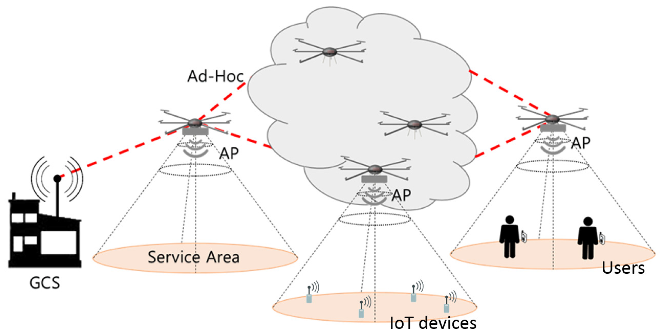
To improve drone teamwork, we previously proposed a multi-drone platform [6,7], comprising two major components: GCS and a drone fleet. The GCS collects information regarding the drones in the fleet, e.g., geographic information, and it plans and manages the drone fleet missions. The fleet is a group of multiple drones that receive the mission from GCS and perform the mission as a team. We considered several case studies, and in particular implemented drone assisted wireless communication for network disabled areas. In this study, drones are equipped with an additional network interface to provide network access to users and Internet of Things (IoT) devices, even in disaster areas or emergency situations, as shown in Figure 1. To actualize drone assisted wireless communications, it is most important to guarantee connectivity among drones and GCS. Since connection loss means that the GCS loses control of drones in a multi-drone control system, it is essential to construct a reliable and efficient network. However, messages are generally exchanged via wireless ad-hoc network, which is unreliable and frequently disconnected, and drone mobility aggravates network instability.
Many studies have modified existing routing protocols, such as the mobile ad-hoc network (MANET), to provide a suitable network for drone systems [8,9,10]. However, there are fundamental differences between existing MANET and drone system network requirements.
- Drones can move in any direction in three-dimensional air space, in contrast to ground nodes that can effectively only move in two-dimensions. Thus, drones can be deployed at any three-dimensional location forming significantly more complicated network topologies.
- Drones have much higher level of mobility than MANET nodes, hence network topology frequently and significantly changes.
- Line of sight (LoS) is usually assured in the air since there are usually no obstacles. Thus, communication range between drones can be significantly larger than between ground nodes, and link cost estimation can be simplified.
- Guaranteed connections among drones are essential. Disconnection of any link may cause critical problems because control messages are transmitted through multi-hop communication.
Therefore, MANET based routing protocols fundamentally have significant limitations, as follows.
- They are not ideal for drone systems, where link quality rapidly changes and node mobility is high, since their original target nodes have limited mobility.
- They cannot utilize GCS, which is a significant component of drone systems, because they are fundamentally based on MANET protocols.
- They inevitably incorporate fundamental MANET protocol limitations, such as constant exchange of HELLO message and repetitive path finding.
These limitations significantly degrade drone system performance, hence MANET based routing protocols are unsuitable for drone networks.
To overcome these limitations, we focused on GCS advantages, since GCS is an essential component of drone networks, containing drone position and movement schedules [11]. Taking our preliminary work [12] further, we propose GCS-routing, a new routing protocol for drone networks that maximizes GCS utilization. This provides many advantages for drone networks, with the two most significant advantages as follows.
- GCS can estimate link costs using drone position and movement information. Thus, drones are only required to detect a link failure, which can be achieved by counting beacon messages sent from neighboring drone access point (AP) interfaces.
- GCS knows the drone mobility schedules, hence it can predict topology changes and notify new routes to each drone in advance. Thus, network disconnected time, which is extremely crucial for controlling drones due to their mobility, can be minimized.
We implemented GCS-routing on real drones and GCS, and evaluated GCS-routing performance in various experiments, e.g., video [13]. In addition to evaluations using real drones, we conducted many simulations to support experimental results and analyze GCS-routing from more diverse perspectives. In all the experiments and simulations, GCS-routing outperformed existing protocols in terms of average throughput, throughput stability, and disconnection time.
The major contributions of this paper can be summarized as follows.
- Proposing a routing protocol and defining a link cost metric for drone networks to control multiple drones as a team
- Implementing the proposed routing protocol on actual drones and evaluating the performance of the protocol with a fleet of drones
- Devising a new GCS onto which the proposed routing control scheme was installed to collect topology changes and disseminate routing tables (current commercial drones and GCS products do not have this type of network routing function)
2. Related Work
Several previous studies have considered aerial networks, such as unmanned aeronautical ad-hoc networks [14], airborne network [15], UAV ad-hoc network [16], etc. However, despite the different names, these have largely only considered aerial ad-hoc networks. The flying ad-hoc network (FANET) was subsequently defined [17], where all UAVs constituted an ad-hoc network but only a subset communicated with the GCS. FANET nodes fundamentally move more freely and have higher mobility than nodes in traditional networks such as MANETs or vehicular ad-hoc networks (VANETs). Thus, it is essential to guarantee reliable peer-to-peer connection among FANET nodes for collaboration and coordination between multiple UAVs.
Since FANET is a new form of MANET, most studies modified existing MANET routing protocols, i.e., proactive (PRP) and reactive (RRP) routing protocols, to make them suitable for FANET. For example, Alshabtat et al. proposed directional optimized link state routing protocol (DOLSR) [8] based on optimized link state routing protocol (OLSR) [18], one of widely used PRPs, that minimized the number of multipoint relays by using UAVs equipped with directional antennas. They verified that DOLSR reduced both end-to-end delay and the number of overhead packets by simulation. In contrast, Brown et al. developed a FANET testbed [9] based on a commonly employed RRP, dynamic source routing (DSR) [19]. Forsmann et al. also proposed a routing protocol using time slot allocation to coordinate communication between UAVs [10] based on ad-hoc on-demand distance vector routing (AODV) [20]. Simulation results showed that the proposed routing protocol minimized packet drops and improved communication quality of service.
Thus, the various routing protocols were not ideal for FANET where link quality rapidly changes and node (drone) mobility is high. Previous protocols also failed to consider GCS, which is the most significant FANET component. In a typical FANET scenario, GCS is essential to monitor UAV information and control them [11]. However, previous protocols were not able to utilize GCS because they were fundamentally based on existing MANET protocols. Consequently, the protocols inherited MANET protocol limitations, such as constant exchange of HELLO message and repetitive path finding, which significantly degrade FANET performance. To overcome these limitations, we propose GCS-routing designed for FANET to maximize GCS utilization.
GCS-routing has advantages compared to previous approaches from several perspectives.
- In contrast to previous routing protocols that were based on MANET protocols, GCS-routing was fundamentally designed for FANET and makes full use of the GCS, enabling FANET to overcome MANET limitations. The proposed routing can predict topology changes and react to them immediately, since the GCS knows the drone movement schedules. Removing the requirement for periodic HELLO messages for neighbor discovery or link cost estimation means that GCS-routing significantly reduces current protocol overheads, making it suitable for high mobility drones.
- Most previous protocols were only evaluated through simulations, without experiments using real drones, even though general network simulators cannot fully support aerial conditions and specifications [17]. Implementing drone networks in the real world is challenging, and development of new routing protocols for drones is difficult. In contrast to the existing work, we implemented GCS-routing on real drones and GCS, and verified the performance of GCS-routing in various experiments. As discussed above, GCS-routing improves overall network performance by reducing network overhead. Thus, it is compatible with systems or algorithms for networks composed of multiple nodes. For example, GCS-routing can be used with systems that require large network bandwidth, such as drone systems that incorporate continuous video transmission [21,22,23], and algorithms that optimize bandwidth usage by considering the physical characteristics of various nodes [24,25,26,27,28]. In addition, with an analytical model of communication recovery probability in emergency situations [29], GCS-routing can be utilized for drone assisted wireless communications more effectively.
3. GCS-Routing Design
This section explains GCS-routing design. Section 3.1 presents an overview of GCS-routing operations, and Section 3.2 presents the route management process in detail. Section 3.3 describes determination of link failure and link cost, and Section 3.4 analyzes transient loops and proves GCS-routing to be fundamentally loop-free. Finally, Section 3.5 analyzes route update cost.
3.1. GCS-Routing Overview
The operations in GCS-routing were divided into two major phases: initialization and maintenance. In the initialization phase, GCS generates routing table for each drone in a centralized manner based on the distance between drones. Since LoS environment is usually guaranteed in FANET, it is reasonable to estimate the link cost based on distance. In the maintenance phase, GCS updates and sends routing tables if the network topology changes due to the drones’ mobility. Since GCS knows future drone locations, future topology can also be predicted.
In some cases, LoS may not be guaranteed. To deal with this problem, each drone monitors link failures between itself and its neighbors by counting the number of received beacons from the neighboring drones’ AP interface (not their ad-hoc interface). Broadcasting beacons does not affect routing performance in ad-hoc networks because periodic beacon broadcasts by AP interfaces are enabled by default. When a drone detects an obstacle or a link failure, it reports the failures to GCS. The GCS then updates the link cost and transmits the new routing table to the corresponding drones.
Figure 2 shows the proposed GCS-routing architecture composed of two main components: GCS and drones. The GCS consists fleet management and route management modules. The fleet management module plans and generates flight commands to each drone, tracks drone position and movement schedules, and hands this information to the route management module. The route management module constructs routing tables and updates link cost in a centralized manner. The GCS then sends routing tables to each corresponding drone through the ad-hoc interface.
Drones include communication and flight management modules. The communication management module updates its routing table using route information sent from GCS, and continuously monitors link failures between itself and neighbors. If link failure is detected, error reports are sent to GCS through the ad-hoc interface. The flight management module relays flight commands from GCS to the drone and reports sensor information to GCS.
3.2. Routing Table Management
We explain how GCS manages routing tables of drones and GCS, and Algorithms 1 and 2 describe GCS-routing operations.
| Algorithm 1 GCS-routing operations in GCS. |
|
3.2.1. GCS-Routing Operations in GCS
Algorithm 1 shows GCS-routing operations in GCS, which were classified into initialization, distribution, and maintenance phases. In the initialization phase (Lines 1–3), i.e., drones are not deployed yet or a route between drones is not constructed yet, GCS estimates link costs among drones based on drone geographic information. The GCS then generates a routing table using Dijkstra’s algorithm and applies the routing table to itself.
In the distribution phase (Lines 4–10), GCS distributes routing tables to each corresponding drone while preventing loop construction. The GCS routing table is already constructed, hence GCS has a tree where GCS is a root node. After generating drone routing tables, GCS creates an aggregated route message, , for each subtree, t, where the one-hop distance child node of GCS is a root node. comprises routing tables for drones in subtree t. Subsequently, GCS distributes to its child nodes that then perform the remaining distribution process (see Algorithm 2).
| Algorithm 2 GCS-routing operations in the drone. |
|
In the maintenance phase (Lines 11–19), when network topology changes due to drone movements or link failure is reported, GCS updates the drone routing tables. As discussed above, GCS manages and schedules drone movements, so it knows drone final destinations. Thus, before the actual topology change, GCS can predict network topological changes and generate routes for future topology. When drone movements are scheduled, GCS generates new route tables and issues them to the corresponding drones using the same distribution strategy of Algorithm 1. The topology also changes when a link failure occurs due to obstacles between drones. When GCS receives a link failure report from a drone, it carries out the cost update process. GCS updates the failure link’s cost and regenerates drone routing tables. However, in the maintenance phase, GCS distributes routing tables only to drones that need to be updated, avoiding unnecessary communications and operations.
3.2.2. GCS-Routing Operations in the Drone
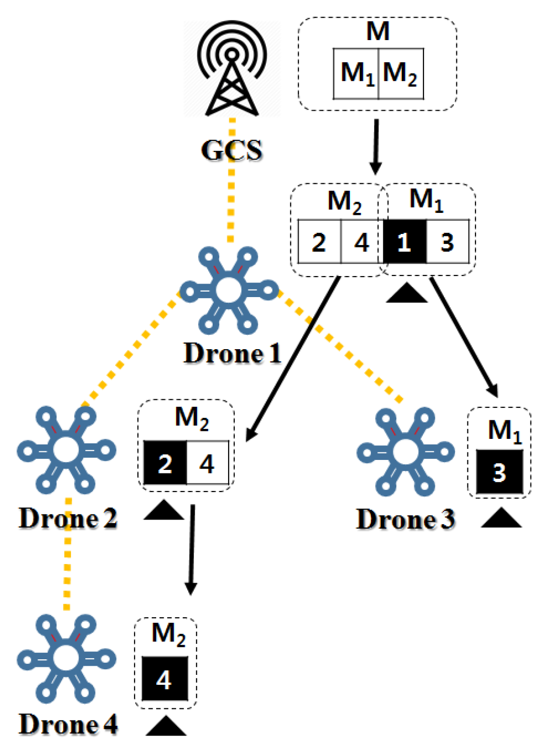
Algorithm 2 shows that operations in a drone can be divided into route update and link monitoring. In the route update phase (Lines 1–15), the drone parses the routing message, m, addressed to itself from the received aggregated route message, M. It then compares new routes in m with old routes and updates only changed route entries for efficiency. The drone deletes its routing table from M and classifies the remaining M into , , ⋯, for its subtrees to generate new aggregated route messages. The subtree root is the received node’s one-hop child node. The newly generated aggregated messages are then issued, and the process is repeated until M reaches the leaf nodes. Consequently, routing tables of all drones can be maintained up-to-date. Figure 3 shows an example of distributing the routing table in GCS-routing. Each drone extracts routing table information from corresponding data in the aggregated route message, and then sends the remaining data to the child node.
In the link monitoring phase (Lines 16–21), a drone scans for link failures between itself and neighbors periodically based on the reception rate of beacons from neighbors. As discussed above, beacon broadcasts conducted by AP interfaces do not affect routing performance in ad-hoc networks. If a link failure is detected, the drone broadcasts a link failure message. Neighboring drones receive the message and forward it to the GCS.
3.3. Link Cost Metric
In common MANET routing protocols, drones periodically broadcast HELLO messages to estimate link costs and detect link failures. In contrast, drones in GCS-routing conduct link cost estimation and link failure detection without HELLO messages. This section explains link cost estimation and detection of link failure in GCS-routing.
3.3.1. Cost Initialization
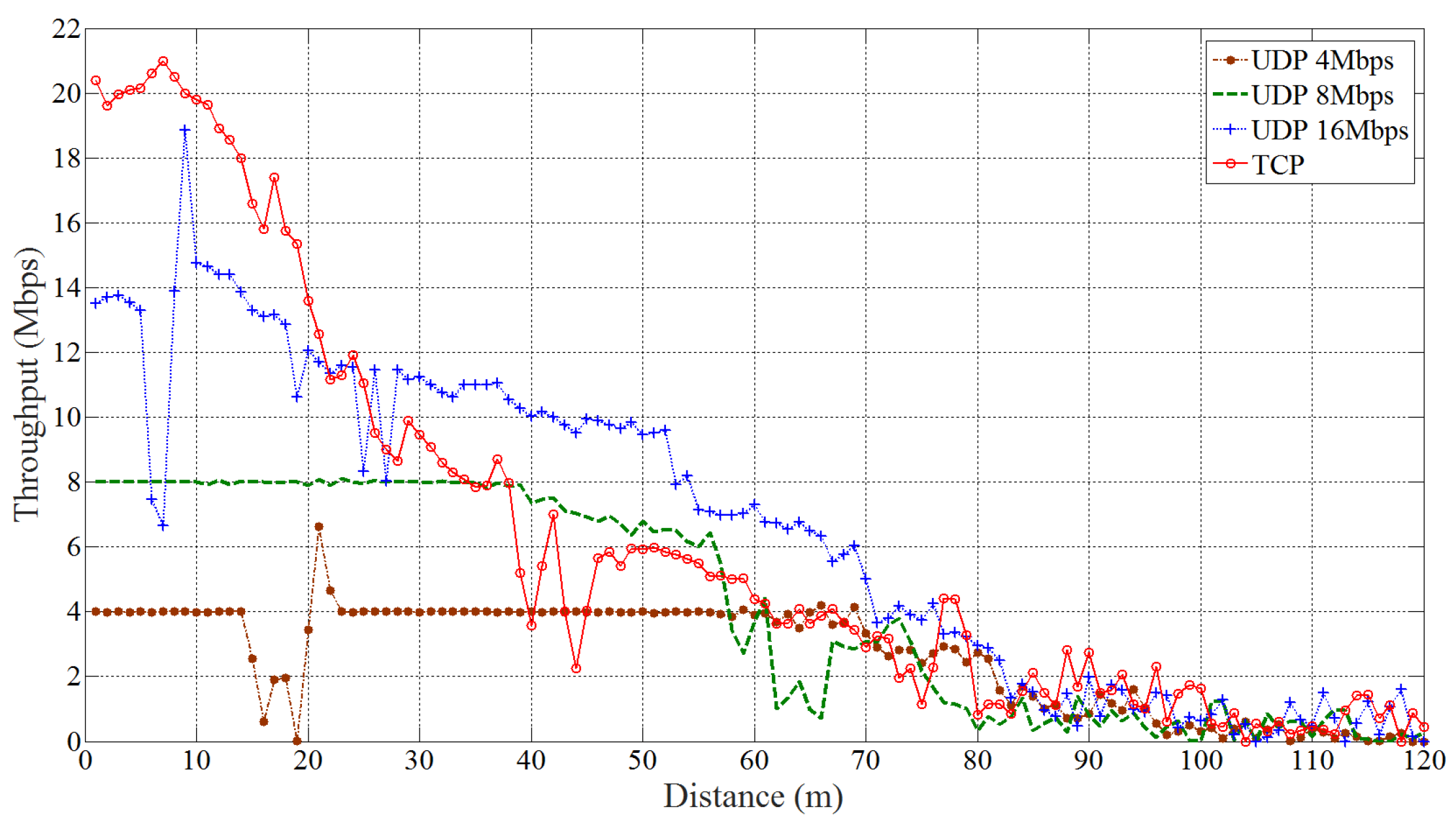
Since GCS-routing is an aerial network routing protocol, we must consider environmental characteristic of aerial networks. Most significantly, LoS between drones is usually guaranteed. Thus, distance between two drones is proportional to the link cost between them. We conducted an experiment to confirm the relationship between drone distance and throughput. One drone hovered at 10 m altitude, while the other drone flew away from the hovering drone at constant 2 m/s. We measured TCP and UDP throughput flows at 4, 8, and 16 Mbps. Data were transmitted through the network interface using IEEE 802.11g. Figure 4 shows that, regardless of the protocol or data rate, throughput decreased proportionally with distance. Data transmissions fluctuated, but were disconnected at almost the same distance, exceeding 80 m.
We normalized the data into [0, 1] to identify common features,
where is the throughput at distance d; and and are the maximum and minimum throughput, respectively. We then calculated the average of all datasets to generalize results from various transmission rates, as shown in Figure 5. The fact that mean of normalized data is 0.8 indicates that the best performance of link was 80% of the ideal case. Performance was approximately 50% of the best performance when m, implying that it takes twice the time to deliver the same number of data. Thus, link cost can be estimated using the reciprocal of the fitted curve in Figure 5. The resulting cost function indicates the amount of time to deliver data through the link at the given distance.
There was significant difference between theoretical and experimental data rates outdoors, consistent with many previous studies [30,31,32]. Thus, it is more appropriate to use the experimental link cost estimation function rather than the theoretical result. Many studies have experimentally established communication standards’ data rates, hence GCS-routing used suitable previous results depending on the communication module employed. For example, estimated throughput, , at distance d using IEEE 802.11g can be expressed as shown in Equation (2) according to [33].
3.3.2. Cost Maintenance
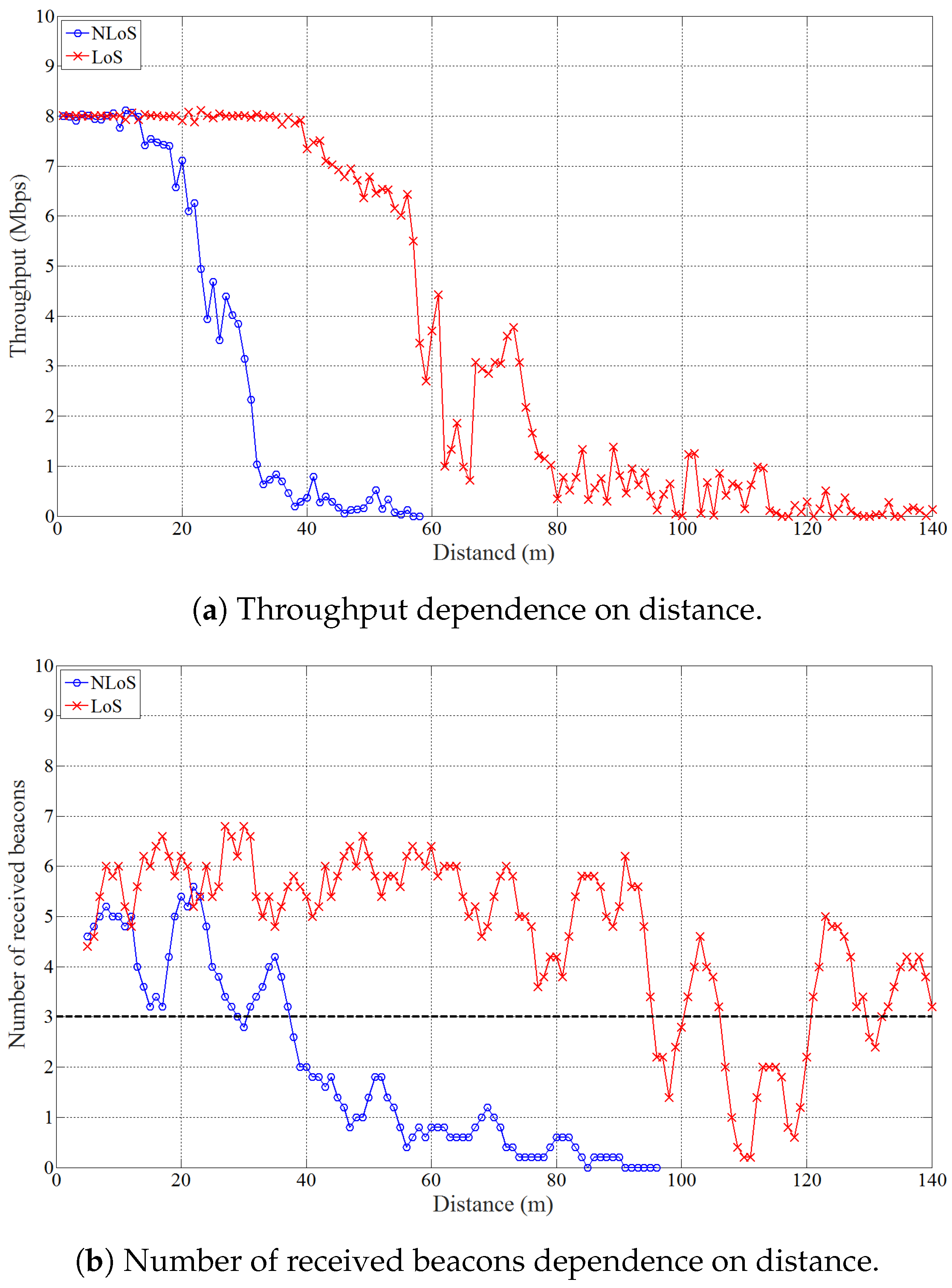
Link costs for GCS-routing were initialized based on drone geographic information. To determine the link costs correctly, we considered not only the distance but also obstacles that could exist. To detect a link in non-LoS (NLoS), each drone counts the number of beacon messages received from neighboring drone APs. We conducted experiments similar to that of Figure 4, but with 8 Mbps UDP flows with a 4.5 cm thick metal obstacle between drones to make the link NLoS. Each second, one drone monitored the average number of received beacons for the past 5 s, as shown in Figure 6. Throughput decreases more sharply in NLoS than LoS environments, with transmissions in NLoS suspended two times earlier than in LoS. The average number of received beacons decreased to fewer than 3, although the distance was close enough to communicate fully in LoS. Thus, we set the threshold count = 3, i.e., if the average number of received beacons is fewer than 3, the drone reports link failure to GCS.
GCS-routing uses a beacon message broadcast in a different radio band from that used in the ad-hoc network, and periodic beacon broadcasts by AP interfaces are enabled by default. Thus, the process explained above does not affect ad-hoc network communication quality.
3.4. Routing Loops in GCS-Routing
This section analyzes routing loops in GCS-routing. We first consider a simple example where a transient loop is formed and show how the network becomes loop-free in GCS-routing. Subsequently, we theoretically prove GCS-routing to be loop-free.
3.4.1. Transient Loops in GCS-Routing
It is essential to guarantee loop-free operation for routing protocols. In GCS-routing, transient loops may be formed during route redistribution when a node receives a new routing table but its child nodes have not received the updated routing table yet. However, since route messages are distributed in a hop-by-hop manner from the closest drone to the farthest drone from the GCS, transient loops eventually disappear, and the network becomes loop-free. Figure 7 shows an example scenario where a transient loop is formed during route update. The numbers show link costs, and the network consists of three nodes. Figure 7a shows the initial routes to node C from nodes A and B. means that Z is the next hop from node X to node Y. Thus, means the next hop from node A to node C, means the next hop from node B to node C, and similarly for and .
In the example scenario, if the link between nodes A and C is broken, GCS-routing creates new routing tables for each node. As described in Section 3.2, routing tables are distributed in a hop-by-hop manner. Thus, node A receives a new routing table from GCS and updates to B, i.e., . However, node B’s routing table is not yet updated, . Figure 7b shows that a transient loop between nodes A and B is formed if node A tries to transmit data to node C, and the presence of the transient loop means the data cannot be transmitted to node C. When node B receives the new routing table from node A, it updates to C, and the network becomes loop-free. Then a new routing table is transmitted to node C, both and are updated to B, and the network converges, as shown in Figure 7c.
3.4.2. Loop-Free GCS-Routing Proof
We formally prove that GCS-routing is loop-free. Let be a weighted directed graph, with g: representing a flying ad-hoc network where each vertex represents a drone or GCS, and an edge is incident to two vertices when both vertices are in transmission range of each other. We assume that membership in the vertex set, , is quasi-static and G is always connected. (This assumption is reasonable since GCS controls and manages one or more drones to accomplish a given mission.) The edge set, , can be changed depending on drone mobility and link state. Since GCS-routing uses distance (based on GPS information) as the routing metric, G cannot have negative weight cycles. Let <> (, ) be a sequence of distinct time instants, , when the network topology changes due to mobility and link state.
Lemma 1.
GCS-routing generates a shortest paths tree rooted at each vertex s in . (“Shortest paths tree rooted at vertex s” means that the GCS-routing algorithm returns a directed tree rooted at s, such that it contains all vertices and every tree path to each vertex is the shortest path in the given graph.)
Proof.
GCS-routing used edge relaxation such as Dijkstra’s or Bellman–Ford’s algorithm to generate shortest paths to all the vertices in for a given source vertex, s. Thus, from many well-known theorems [34], GCS-routing generates a shortest paths tree rooted at s in . ☐
Then, let a shortest paths tree rooted at s be at an arbitrary time instant t.
Lemma 2.
For any time interval , , is not changed.
Proof.
Suppose is changed within the interval. Let be the time instant when the topology is changed. Then, = since should be in <>. This contradicts the assumption. ☐
Once a shortest paths tree, , rooted at s, is constructed by GCS-routing after time instant , it is continuously used to route all the packets from node s to the other vertices until . is when GCS initiates GCS-routing after perceiving a change in the network topology. Then GCS-routing generates a new shortest paths tree, , rooted at each s.
Lemma 3.
There exists a short interval , , when the subgraph that GCS-routing generates for vertex s is not a tree after GCS-routing is initiated, i.e., the topology is changed.
Proof.
When GCS-routing notices one or more topology changes at time instant , it takes finite time to make different from . Therefore, any subgraph of can be possible until is completely constructed. Hence, there could be a cycle between two nodes and . The cycle is constructed in the way that one part of the cycle comes from and the other part is from , and hence is not a tree. ☐
Lemma 4.
Any short interval , , when the subgraph that GCS-routing generates for vertex s is not a tree is eventually terminated if all the routing messages from GCS are eventually delivered to all the participating nodes.
Proof.
Since we assume membership of is not changed and any vertex is connected to at least one other vertex, all routing control messages generated by GCS-routing are eventually delivered to every vertex. Therefore, vertex s comes to have a new shortest paths tree based on newly delivered routing messages. ☐
Theorem 1.
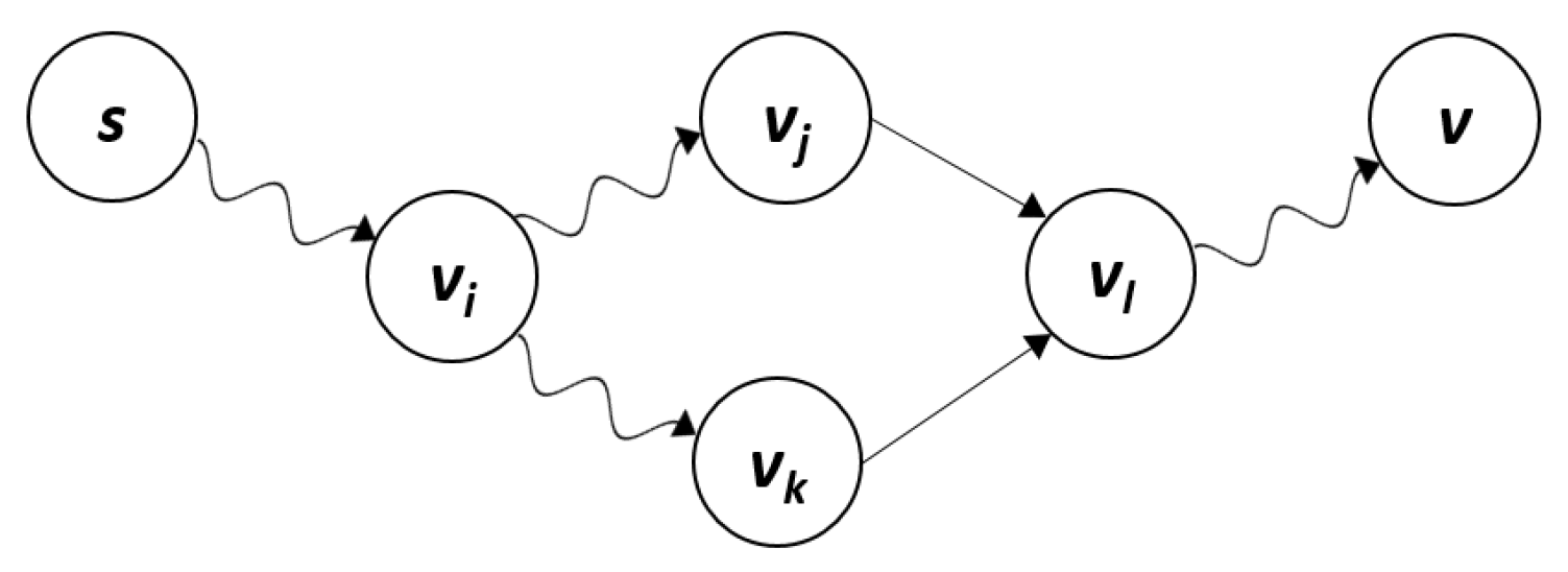
There is one shortest path from s to v for any vertex at any time instant any interval , .
Proof.
Suppose there are two simple paths from s to vertex v: and . The former can be decomposed into , and the latter into (see Figure 8). Then, the predecessor vertex of vertex on from s to v is , and the vertex on is , which implies since GCS-routing generates a shortest paths tree rooted at s. This contradicts the assumption. ☐
Consequently, GCS-routing generates a shortest paths tree for each vertex s that can be used to deliver packets generated by s, and it maintains the tree even if topology changes occur, except for the short period when all routing messages are delivered to all drones.
3.5. Complexity Analysis
In terms of scalability, low cost route update is an important requirement for routing protocols. Common PRPs periodically issue and exchange HELLO messages, whereas GCS-routing does not issue HELLO messages. Routing table management for GCS-routing also has much lower overhead than other protocols in respect of the number of route update messages. Let us assume a network composed of N randomly deployed nodes. Route update cost can be measured in terms of communication complexity, i.e., the number of messages required to perform a protocol operation [35].
Suppose destination sequenced distance vector routing (DSDV) [36], one of the most widely used PRPs, is applied to the network. DSDV has two types of route update messages. One immediately updates drastically changed routes, and the other periodically updates the overall route. Communication complexity of the former case is , since a route update message would be forwarded by all nodes in the network in the worst case. Communication complexity for the periodical route update is much larger. In a network where every node periodically broadcasts its own route table, each table would be forwarded N times in the worst case. Therefore, communication complexity is .
In contrast, OLSR [18] chooses one or more nodes among neighboring nodes to be multipoint relay (MPR) nodes, and topology control (TC) packets are transmitted by MPR nodes only. Thus, OLSR reduces the number of packet transmissions for route update. However, in the worst case, all OSLR nodes except the end node are MPR nodes, hence communication complexity for route update in OLSR is also , similar to DSDV.
On the other hand, consider GCS-routing applied to the same network. Two types of route update messages are used in GCS-routing for initialization and route maintenance. The worst case is when all node route information is updated, which is identical to initialization. As discussed above, GCS generates a tree to issue route update messages, where GCS is the root. GCS then issues each aggregated route update message to corresponding subtree, and each drone repeats the operation. Therefore, every node in the network receives the aggregated route update message one time only. Thus, communication complexity is , significantly lower than DSDV or OLSR, and hence more efficient.
4. Performance Evaluation
We conducted various experiments to evaluate GCS-routing performance, and selected two MANET PRPs: DSDV and OLSR, as comparison protocols. RRP end-to-end delay is very large due to frequent route establishments before data transmissions [37]. Thus, since high control rate is essential for drone networks, RRPs are inappropriate and were not considered for performance evaluations. On the other hand, PRPs update routing tables periodically, so they have a relatively short end-to-end delay compared to RRPs. We implemented GCS-routing, DSDV, and OLSR on real drones and GCS, and evaluated GCS-routing performance in various experiments. We then conducted simulations to support the experiment results, thoroughly verify GCS-routing performance, and evaluate GCS-routing from more diverse perspectives. The evaluations and simulations focused on throughput stability and network disconnection time, which significantly affect drone control through a network.
4.1. GCS-Routing Implementation
We used F550 ARF KITs from DJI as drone frames and assembled them ourselves, as shown in Figure 9. We adopted ODROID-U3 of HardKenel for drone computing and networking operations, and Pixhawk autopilot [38] of 3D Robotics as the flight controller. ODROID-U3 and Pixhawk were connected via USB to a UART module.
We used two ipTime N600UA modules as communication interfaces. The following section details experiments where drones were connected with ad-hoc network using IEEE 802.11g as the primary interface. Each drone could act as an AP using a secondary interface to provide network to users located in the service area of the drone. The secondary interface also used IEEE 802.11g, but used a different channel from the ad-hoc network channel to avoid influencing routing performance. We implemented GCS-routing using C on ODROID-U3 with Linux network libraries, and used Babeld and OLSRd as DSDV and OLSR protocols, respectively. These protocols were implementations of RFC 6126 [39] and RFC 3626 [18], respectively. We built six drones and implemented GCS with C on a laptop computer running Linux.
4.2. Experiments
This section details the various experiments and outcomes using the devices and drones discussed above.
4.2.1. Route Update Time and Throughput
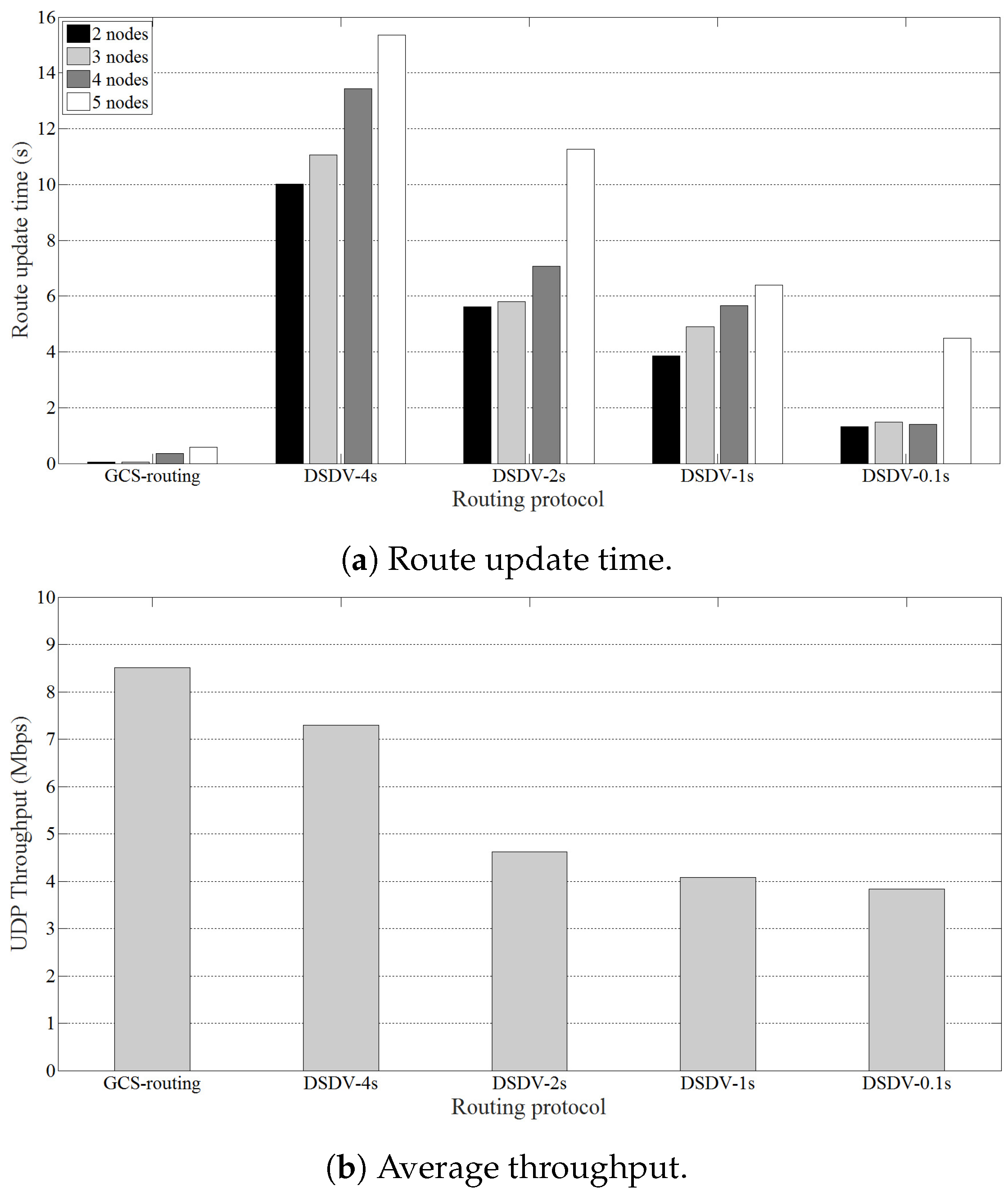
We evaluated GCS-routing route update time and throughput. We configured a network comprising 1–4 drones, then added a new drone to the network and measured the time until all drones updated the optimal route to each other. Since the HELLO interval for PRPs significantly affects throughput and route update time, we used different HELLO intervals for evaluation. Babeld based on DSDV dynamically adjusts the HELLO interval during data transmission, whereas dynamic adjustment of HELLO interval is not mentioned in the OLSR protocol RFC, and OLSRd does not dynamically adjust the interval during data transmission. Thus, we compared GCS-routing with DSDV with different HELLO intervals, and did not consider OLSR for these evaluations.
Figure 10a shows that DSDV route update times decrease as the HELLO interval shortens. However, they were always greatly larger than that of GCS-routing, i.e., GCS-routing immediately reacted to topology changes. As discussed in Section 3.5, GCS-routing complexity is significantly lower than DSDV because GCS-routing does not issue HELLO messages and hence routing table management has much lower overhead.
In addition to the route update time, we also measured UDP data throughput between two drones using iperf. Figure 10b shows that average DSDV throughput significantly decreases as HELLO interval shortens, but is always significantly lower than that of GCS-routing. Thus, throughput stability is significantly affected by shorter HELLO interval. Consequently, HELLO messages with shorter intervals reduce route update time, but degrade network throughput. Therefore, it is more appropriate for drone networks to use GCS-routing, which outperforms other protocols in terms of both throughput and route update time.
4.2.2. Performance Evaluation for the Mobility Scenario
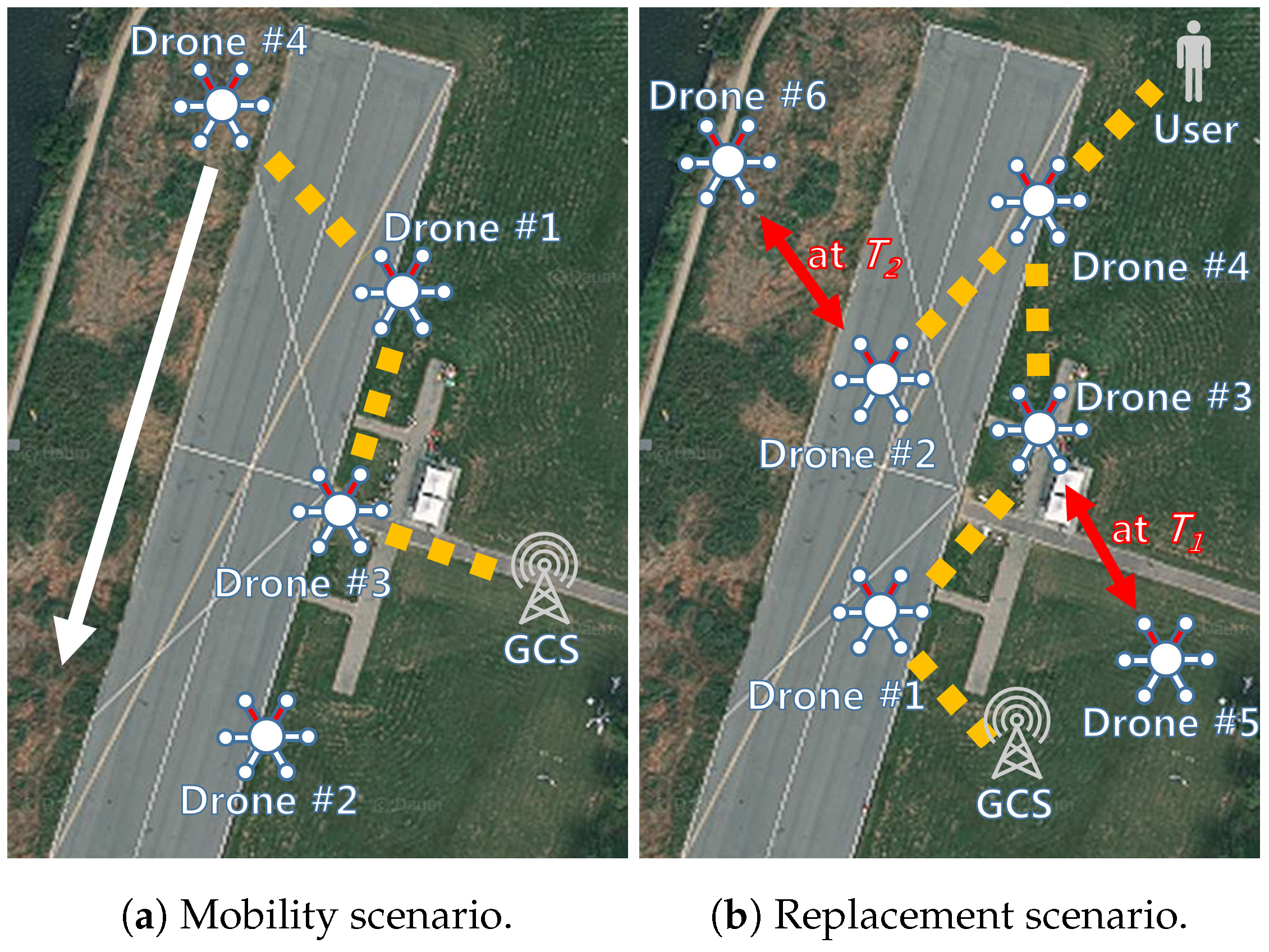
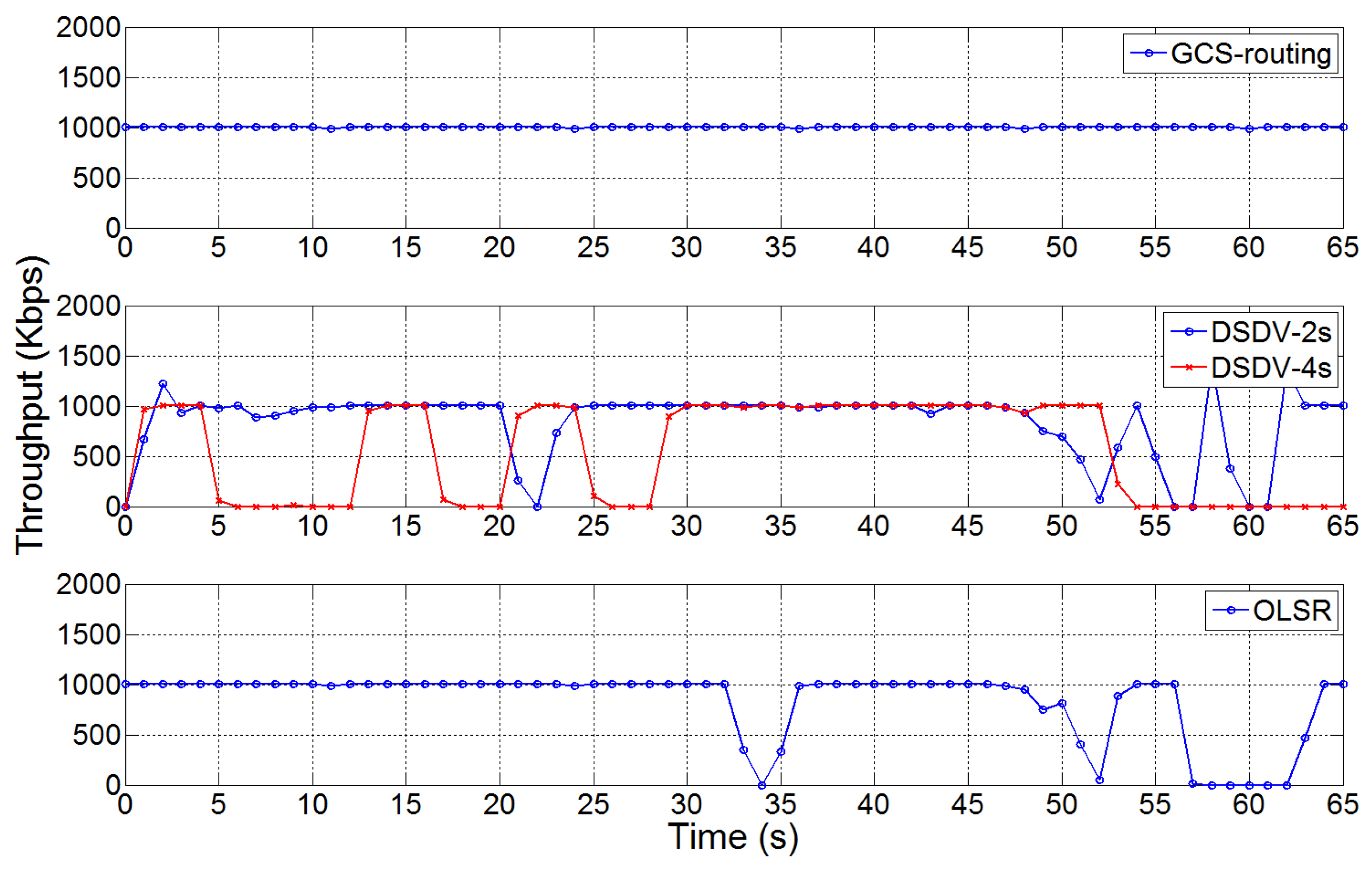
We evaluated GCS-routing performance for the mobility scenario shown in Figure 11a, where Drone 4 generating 1 Mbps UDP traffic to GCS moves along the arrow at 2 m/s. GCS-routing updated drone routes based on the mobile drone’s location, as shown in Figure 12. GCS-routing redistributed routing tables only twice (at 31.5 and 46 s), and network disconnection time due to the route update was only approximately 1 s for each redistribution. Thus, GCS-routing reacted to topology changes immediately and would be suitable for real-time applications. In contrast, after Drone 4 lost connection with Drone 1, DSDV with 4 s HELLO interval (DSDV-4s) could not reconfigure a routing table, because Drone 4’s velocity was too fast for DSDV-4s to configure a valid routing table before the next topology change. For example, when a route passing through Drone 3 was configured, Drone 4 was already out of communication range of Drone 3, so the new routing table was no longer valid. Throughput was still unstable when HELLO interval was reduced to 2 s. Network disconnection time was significantly longer than that of GCS-routing.
On the other hand, OLSR provided relatively stable throughput compared with DSDV. OLSR updated routing tables four times, at 8.5, 44.5, 55, and 67.5 s, but the first and the third updates were unnecessary. Thus, OLSR wasted more than 9 s due to frequent and unnecessary route updates. Table 1 shows that GCS-routing achieved higher average throughput and superior stability compared with both DSDV and OLSR.
4.2.3. Performance Evaluation for the Replacement Scenario
Battery limitations mean drone flight time is generally less than 20 min [1]. Thus, replacement functionality is essential to prolong drone system service time. If remaining battery energy becomes low, GCS should send a return-to-home command to the depleted drone and assign a new drone to that service area. If a drone experiences failure due to any problem, e.g., collision or hardware malfunction, a new drone should be deployed to perform the designated mission. In these situations, it is important for drones to update routing tables with minimum overhead to preserve connectivity.
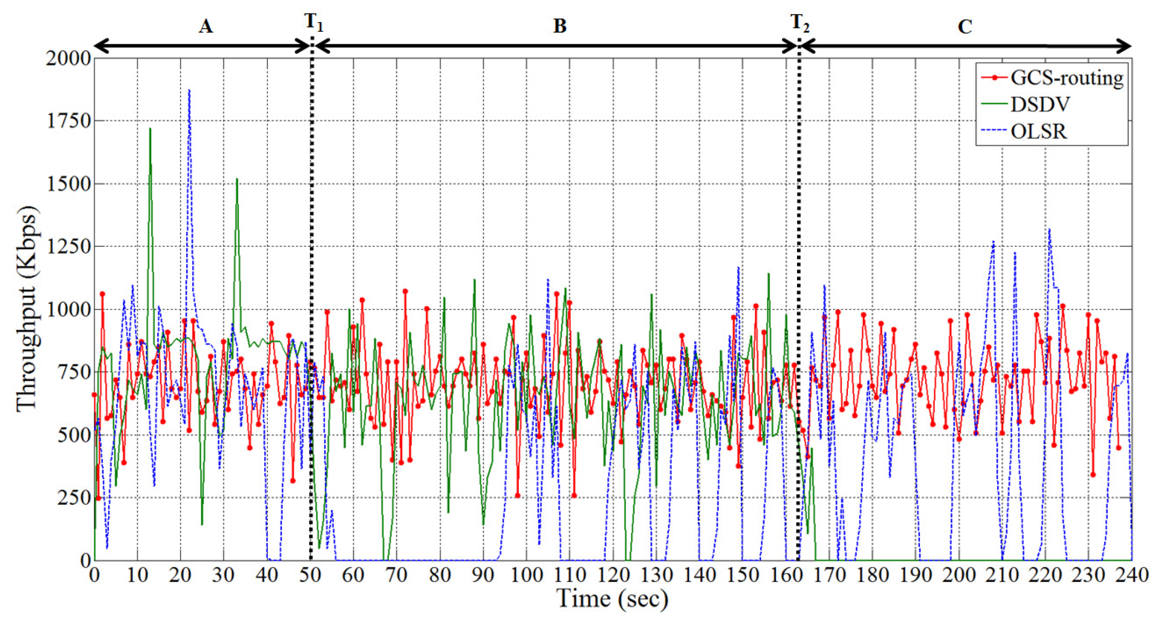
Figure 11b shows the drone replacement scenario where the user located in Drone 4’s service area sends 1 Mbps UDP data using iperf to Drone 1. Drones 5 and 6 were waiting for future replacement. At , Drone 3 returned to the base station, and Drone 5 replaced it, and Drone 6 replaced Drone 2 at . We measured UDP throughput of GCS-routing, DSDV, and OLSR, as shown in Figure 13.
Network topology changed at and , so connections were disconnected until new routes were established. Table 2 shows network disconnected time for each replacement. GCS-routing takes approximately 1 s to update routes between the two drones on average, whereas DSDV takes 17.5 s, significantly longer than both OLSR and GCS-routing. This is because the DSDV HELLO interval was 4 s, whereas OLSR interval was 2 s. Since OLSR detects events every 0.1 s, it can minimize delay to set up the routing table again. However, OLSR network disconnected time was 3 times that of GCS-routing. Thus, GCS-routing immediately reacted to network topology changes and stabilized the new network very quickly. The drone network supervisor loses drone control during network disconnected time, which is fatal for real-time applications. If drones remain uncontrolled for a long period, they could collide with obstacles or other drones.
GCS-routing also provided more uniform network service quality than the other protocols, as shown in Table 3. DSDV and OLSR standard deviations were relatively high due to the HELLO messages. Thus, GCS-routing exhibited superior network stability and would be more appropriate for controlling drone networks. The video of the experiment can be found at [13].
4.3. Simulations
In addition to experiments using real drones, we conducted simulations using network simulator 3 (ns-3) [40,41]. We first conducted simulations similar to the real experiments in Section 4.2 to support the experiment results and thoroughly verify GCS-routing performance. We then performed additional simulations to evaluate GCS-routing from more diverse perspectives.
4.3.1. Route Update Time and Throughput
It is critical that drone systems react to topology changes promptly, particularly for real-time applications. Thus, we evaluated GCS-routing performance when topology changes using simulations to investigate route update time and throughput. Similar to the experiment in Section 4.2.1, we configured a network composed of drones, and then added a new drone to the network, using DSDV with various HELLO intervals and GCS-routing. Figure 14a shows the time until all drones updated the optimal route. This result is consistent with the previous experimental outcomes (Figure 10a, Section 4.2.1). Route update times for DSDV were much longer than those of GCS-routing. DSDV could not react to topology changes promptly, whereas GCS-routing reacted immediately due to utilizing GCS and low GCS-routing complexity.
Figure 14b shows that average DSDV throughput decreased as the HELLO interval shortened, due to frequent HELLO message transmission consuming available throughput, hence limiting availability for data transmission. Shorter intervals decreased the time for route update, but degraded throughput. Therefore, GCS-routing is more suitable for drone networks, providing significantly superior throughput and route update time.
4.3.2. Performance Evaluation for the Mobility Scenario
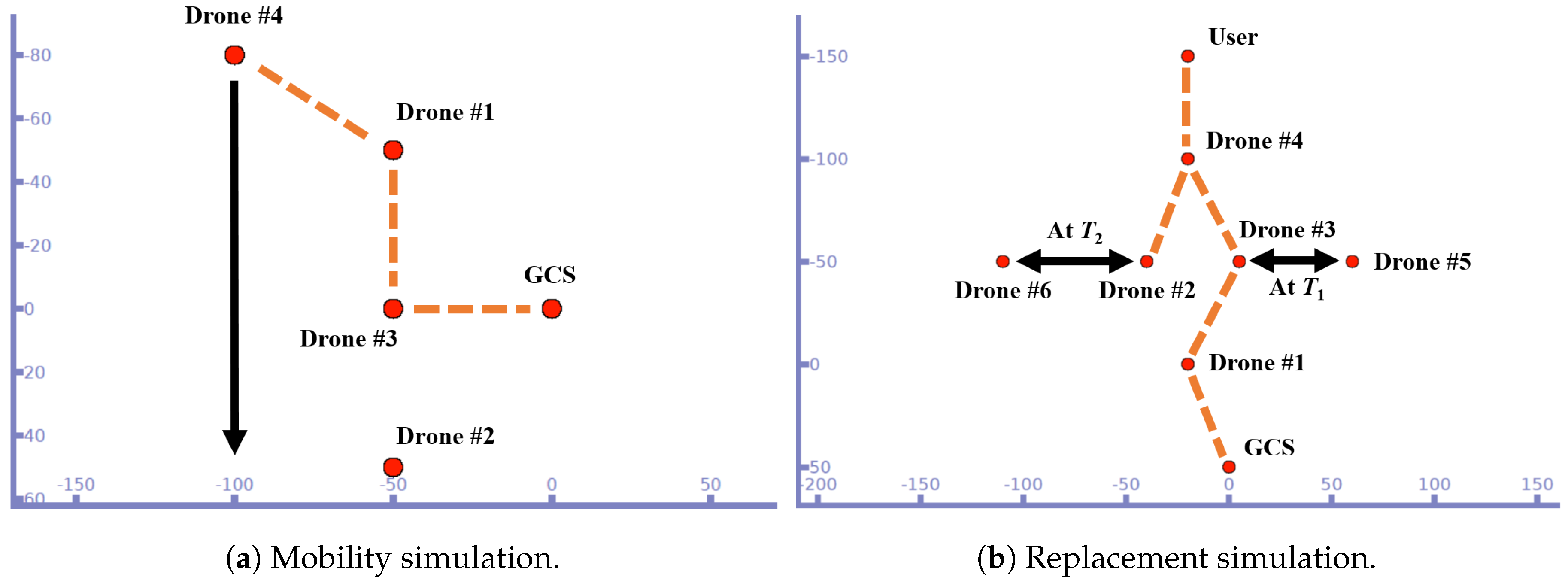
We conducted a simulation to verify that GCS-routing provided reliable routing and stable throughput even with drone movement. Similar to the experiment in Section 4.2.2, Drone 4 sending 1 Mbps UDP traffic to GCS moved along the arrow shown in Figure 15a. GCS-routing updated routing routes based on Drone 4’s geographic information, as shown in Figure 16. Simulation outcomes were strongly consistent with the drone experiment in Figure 12. GCS-routing redistributed routing tables appropriately without unnecessary redistribution, highlighting high efficiency of GCS-routing.
GCS-routing did not significantly degrade data communication, and provided stable network throughput. In contrast, DSDV-4s was unable to respond quickly to changing network topology, hence Drone 4 frequently lost network connection, and throughput fluctuated quite sharply. DSDV with 2 s HELLO interval provided more rapid response to network changes and stable throughput. However, throughput fluctuation was very large compared to the GCS-routing result. There were unnecessary redistributions of routing tables using OLSR, causing network disconnection and large fluctuation. Table 4 shows throughput of the compared protocols, and confirms that GCS-routing provides better network performance.
We also conducted a further mobility scenario experiment. Similar to the previous case, Drone 4 sent 1 Mbps UDP traffic to GCS. However, there was an additional 0.3 Mbps UDP transmission between Drones 1 and 2 to evaluate routing performance in the presence of background traffic in the routing path, as shown in Table 5. GCS-routing throughput decreased compared to the previous experiment due to the background traffic. However, this decrease was relatively very small compared to that of DSDV and OLSR. The standard deviation of GCS-routing was also much less than that of DSDV or OLSR despite the background traffic. Thus, this additional experiment confirmed that GCS-routing provides more stable data communications than other routing protocols even when there was background traffic in the routing path.
4.3.3. Performance Evaluation for the Replacement Scenario
As discussed above, drone replacement is an essential function to prolong the drone system service time. Therefore, we evaluated GCS-routing for the replacement scenario by simulation, as shown in Figure 15b. The user located in the service area of Drone 4 sent 1 Mbps UDP data traffic to Drone 1. At , Drone 3 left the fleet and was replaced by Drone 5. At , Drone 2 was replaced by Drone 6.
Figure 17 shows the resultant GCS-routing, DSDV, and OLSR throughputs, and Table 6 and Table 7 show network disconnected time and throughput standard deviation, respectively. Similar to the real-drone experiment case in Section 4.2.3, GCS-routing exhibited superior performance compared with the other protocols, and immediately reacted to new network topologies.
4.3.4. Performance Evaluation for the TCP Traffic Scenario
TCP is one of the most widely used transport layer protocols along with UDP, and many applications transmit data through TCP. Therefore, we conducted a simulation study to evaluate GCS-routing performance with TCP. Similar to Section 4.3.2 and Section 4.3.3, we evaluated GCS-routing for the mobility and replacement scenario, but employed TCP rather than UDP.
For the mobility scenario, Drone 4 moved along the arrow and sent TCP traffic to GCS without throughput limitation. We conducted this simulation 10 times for each routing protocol, with the outcomes as shown in Table 8. OLSR was omitted because OLSR in ns-3 does not support TCP data communications. GCS-routing provided better network throughput and stability than DSDV. The standard deviations in Table 8 are much larger than those in Table 4 due to larger TCP throughputs than the previous UDP case.
For the replacement scenario, the user located in Drone 4’s service area sent TCP data traffic without throughput limitation to Drone 1. We also conducted this simulation 10 times for each routing protocol, with outcomes as shown in Table 9, Table 10 and Table 11. Network disconnected times of GCS-routing are much shorter than those of DSDV, and GCS-routing provides better network throughput than DSDV. GCS-routing standard deviation was also significantly smaller than that of DSDV. Thus, GCS-routing provided more stable network performance than DSDV.
Thus, the simulations confirmed that GCS-routing provided better network performance than DSDV even when using TCP.
4.3.5. Performance Evaluation for the Large Scale Network Scenario
The previous experiments and simulations confirmed that GCS-routing outperforms other routing protocols in practical situations. We performed an additional simulation for a large network scenario, which would have been difficult to conduct using real drones and devices. Figure 18 shows a simplified view of the scenario. Two end drones conducted 1 Mbps UDP data communication through at least a 26-hop drone network. Distance between consecutive drones on the data communication path was 50 m, so source and destination were about 1300 m apart. To reflect battery limitations of real drones, drones between the end drones were sequentially replaced during the simulation, and 52 drones in total participated in the simulation. As the simulation proceeded, packets were transmitted through different paths as the drones kept moving and were replaced, and at least 24 handovers occurred in simulation period. We conducted this simulation 10 times for each routing protocol.
Table 12 shows that GCS-routing provides superior throughput and network stability than other protocols. Throughputs using OLSR and DSDV were relatively very low due to drone mobility, large number of hops, and frequent handovers. GCS-routing provided stable communication in the large network scenario similar to the previous evaluation results. Thus, GCS-routing redistributed routing tables properly and is also appropriate for large drone networks.
4.4. GCS-Routing Power Consumption
Generally, the major power consumption in a drone is throttling by the motors for flight, as shown in Figure 19. Power consumption increases rapidly as the drone starts flying (throttling up) and falls quickly when the drone stops flying (throttling down). Table 13 shows that throttling up the motors consumed more than 97% of the overall drone consumption. Since flight takes most drone power consumption, it is meaningless to consider power consumption caused by routing operations.
5. Conclusions
Rapid technological development has encouraged applications and services in various areas to consider utilizing drones. Generally, employing multiple drones is superior to a single drone for complex missions, and strong connectivity among the drones is essential. Most previous studies modified earlier MANET protocols to make them suitable for FANET and provide sufficient connectivity. However, these inevitably inherited fundamental MANET protocol limitations, which were not ideal for FANET. To overcome these limitations, we focused on GCS advantages and proposed GCS-routing, designed specifically for FANET. GCS-routing makes the best use of GCS to predict topology changes and react to them immediately without requiring periodic HELLO messages for neighbor discovery or link cost estimation. Therefore, current routing protocol overheads were significantly reduced using GCS-routing, making it suitable for high mobility drones in FANET. We designed and implemented GCS-routing on real drones and GCS, and conducted experiments and simulations to thoroughly evaluate GCS-routing performance from diverse perspectives [13]. Evaluation results confirmed that GCS-routing provided higher and more stable throughput, with considerably shorter network disconnected and route update times compared with other routing protocols. Thus, GCS-routing provided better network performance in many aspects and is more suitable for drone networks than other protocols. GCS-routing makes it possible to construct reliable and efficient networks for multi-drone control systems.
There are several directions for future study. GCS incorporates various information that was not considered in the current study. Therefore, we intend to extend GCS-routing to incorporate diverse information to improve routing algorithm efficiency and performance. Furthermore, this study considered multiple drone networks with GCS-routing, so we plan to develop a testing guideline and benchmark for drone swarm networks.
Author Contributions
Concept, W.L., K.K. and H.K.; Methodology, W.L., J.Y.L., K.K. and H.K.; Software, J.Y.L. and J.L.; Validation, J.Y.L., J.L., S.Y. and S.P.; Original draft preparation, W.L. and J.L.; Review and editing, W.L. and H.K.; and Supervision, H.K.
Funding
This research was supported by the Unmanned Vehicles Advanced Core Technology Research and Development Program through the Unmanned Vehicle Advanced Research Center funded by the Ministry of Science, ICT and Future Planning, Republic of Korea (NRF-2016M1B3A1A01937599).
Acknowledgments
A preliminary version of this paper was presented at the IEEE International Conference on Communications (ICC), IEEE, 2016.
Conflicts of Interest
The authors declare that they have no conflicts of interest.
References
- Floreano, D.; Wood, R.J. Science, technology and the future of small autonomous drones. Nature 2015, 521, 460–466. [Google Scholar] [CrossRef] [PubMed] [Green Version]
- La, W.G.; Park, S.; Kim, H. D-MUNS: Distributed multiple UAVs’ network simulator. In Proceedings of the IEEE 2017 Ninth International Conference on Ubiquitous and Future Networks (ICUFN), Milan, Italy, 4–7 July 2017; pp. 15–17. [Google Scholar]
- Erdelj, M.; Natalizio, E.; Chowdhury, K.R.; Akyildiz, I.F. Help from the sky: Leveraging UAVs for disaster management. IEEE Pervasive Comput. 2017, 24–32. [Google Scholar] [CrossRef]
- Bae, M.; Yoo, S.; Jung, J.; Park, S.; Kim, K.; Lee, J.Y.; Kim, H. Devising Mobile Sensing and Actuation Infrastructure with Drones. Sensors 2018, 18, 624. [Google Scholar] [CrossRef] [PubMed]
- Jung, J.; Yoo, S.; La, W.; Lee, D.; Bae, M.; Kim, H. AVSS: Airborne Video Surveillance System. Sensors 2018, 18, 1939. [Google Scholar] [CrossRef] [PubMed]
- Chung, A.Y.; Jung, J.; Kim, K.; Lee, H.K.; Lee, J.; Lee, S.K.; Yoo, S.; Kim, H. Poster: Swarming Drones Can Connect You to the Network. In Proceedings of the 13th Annual International Conference on Mobile Systems, Applications, and Services, Florence, Italy, 18–22 May 2015; p. 477. [Google Scholar]
- Yoo, S.; Kim, K.; Jung, J.; Chung, A.Y.; Lee, J.; Lee, S.K.; Lee, H.K.; Kim, H. Poster: A Multi-Drone Platform for Empowering Drones’ Teamwork. In Proceedings of the 21st Annual International Conference on Mobile Computing and Networking, Paris, France, 7–11 September 2015; pp. 275–277. [Google Scholar]
- Alshabtat, A.I.; Dong, L.; Li, J.; Yang, F. Low latency routing algorithm for unmanned aerial vehicles ad-hoc networks. Int. J. Electr. Comput. Eng. 2010, 6, 48–54. [Google Scholar]
- Brown, T.X.; Doshi, S.; Jadhav, S.; Henkel, D.; Thekkekunnel, R.G. A Full Scale Wireless Ad Hoc Network Test Bed. 2005, pp. 51–60. Available online: http://citeseerx.ist.psu.edu/viewdoc/summary?doi=10.1.1.121.2433 (accessed on 22 October 2018).
- Forsmann, J.H.; Hiromoto, R.E.; Svoboda, J. A time-slotted on-demand routing protocol for mobile ad hoc unmanned vehicle systems. In Proceedings of the Defense and Security Symposium, International Society for Optics and Photonics, Orlando, FL, USA, 2 May 2007. [Google Scholar]
- Palan, K.; Sharma, P. FANET Communication Protocols: A Survey. 2015. Available online: https://pdfs.semanticscholar.org/49e0/dfb643106bb157dd98ca6e455fcddd31e0da.pdf (accessed on 22 October 2018).
- Lee, J.; Kim, K.; Yoo, S.; Chung, A.Y.; Lee, J.Y.; Park, S.J.; Kim, H. Constructing a reliable and fast recoverable network for drones. In Proceedings of the 2016 IEEE International Conference on Communications, Kuala Lumpur, Malaysia, 23–27 May 2016; pp. 1–6. [Google Scholar]
- Lee, W.; Lee, J.Y.; Lee, J.; Kim, K.; Yoo, S.; Park, S.; Kim, H. Ground Control System Based Routing for Reliable and Efficient Multi-Drone Control System. Available online: https://youtu.be/JgBIPdo2CWQ. (accessed on 11 September 2018).
- Shirani, R.; St-Hilaire, M.; Kunz, T.; Zhou, Y.; Li, J.; Lamont, L. Quadratic estimation of success probability of greedy geographic forwarding in unmanned aeronautical ad-hoc networks. In Proceedings of the Vehicular Technology Conference, Yokohama, Japan, 6–9 May 2012; pp. 1–5. [Google Scholar]
- Cheng, B.N.; Moore, S. A comparison of MANET routing protocols on airborne tactical networks. In Proceedings of the 2012-MILCOM—IEEE 2012 Military Communications Conference, Orlando, FL, USA, 29 October–1 November 2012; pp. 1–6. [Google Scholar]
- Lin, L.; Sun, Q.; Wang, S.; Yang, F. A geographic mobility prediction routing protocol for Ad Hoc UAV Network. In Proceedings of the IEEE 2012 Globecom Workshops, Anaheim, CA, USA, 3–7 December 2012; pp. 1597–1602. [Google Scholar]
- Bekmezci, I.; Sahingoz, O.K.; Temel, Ş. Flying ad-hoc networks (fanets): A survey. Ad Hoc Netw. 2013, 11, 1254–1270. [Google Scholar] [CrossRef]
- Clausen, T.; Jaqcquet, P. Optimized Link State Routing (OLSR). RFC 3626. IETF Networking Group, 2003. Available online: https://tools.ietf.org/html/rfc3626 (accessed on 22 October 2018).
- Johnson, D.B.; Maltz, D.A. Dynamic source routing in ad hoc wireless networks. Mob. Comput. 1996, 353, 153–181. [Google Scholar]
- Perkins, C.; Belding-Royer, E.; Das, S. Ad Hoc on-Demand Distance Vector (AODV) Routing. Technical Report. 2003. Available online: http://www.rfc-editor.org/info/rfc3561 (accessed on 22 October 2018).
- Baseca, C.C.; Díaz, J.R.; Lloret, J. Communication Ad Hoc protocol for intelligent video sensing using AR drones. In Proceedings of the IEEE 2013 Ninth International Conference on Mobile Ad-Hoc and Sensor Networks (MSN), Dalian, China, 11–13 December 2013; pp. 449–453. [Google Scholar]
- Cambra, C.; Díaz, J.R.; Lloret, J. Deployment and performance study of an Ad Hoc network protocol for intelligent video sensing in precision agriculture. In Proceedings of the International Conference on Ad-Hoc Networks and Wireless, Benidorm, Spain, 22–27 June 2014; pp. 165–175. [Google Scholar]
- Wu, C.; Wang, Z.; Yang, S. Drone streaming with Wi-Fi grid aggregation for virtual tour. arXiv, 2016; arXiv:1605.09486. [Google Scholar]
- Tsiropoulou, E.E.; Paruchuri, S.T.; Baras, J.S. Interest, energy and physical-aware coalition formation and resource allocation in smart IoT applications. In Proceedings of the 2017 51st Annual Conference on Information Sciences and Systems (CISS), Baltimore, MD, USA, 22–24 March 2017; pp. 1–6. [Google Scholar]
- Tsiropoulou, E.E.; Mitsis, G.; Papavassiliou, S. Interest-aware energy collection & resource management in machine to machine communications. Ad Hoc Netw. 2018, 68, 48–57. [Google Scholar]
- Lin, C.R.; Gerla, M. Adaptive clustering for mobile wireless networks. IEEE J. Sel. Areas Commun. 1997, 15, 1265–1275. [Google Scholar] [CrossRef] [Green Version]
- Gerla, M.; Tsai, J.T.C. Multicluster, mobile, multimedia radio network. Wirel. Netw. 1995, 1, 255–265. [Google Scholar] [CrossRef]
- Akan, O.B.; Karli, O.B.; Ergul, O. Cognitive radio sensor networks. IEEE Netw. 2009, 23, 34–40. [Google Scholar] [CrossRef] [Green Version]
- Mekikis, P.V.; Antonopoulos, A.; Kartsakli, E.; Alonso, L.; Verikoukis, C. Communication recovery with emergency aerial networks. IEEE Trans. Consum. Electron. 2017, 63, 291–299. [Google Scholar] [CrossRef] [Green Version]
- Matsumoto, A.; Yoshimura, K.; Aust, S.; Ito, T.; Kondo, Y. Performance evaluation of IEEE 802.11 n devices for vehicular networks. In Proceedings of the IEEE 34th Conference on Local Computer Networks, Zurich, Switzerland, 20–23 October 2009; pp. 669–670. [Google Scholar]
- Jansons, J.; Dorins, T. Analyzing IEEE 802.11 n standard: Outdoor performanace. In Proceedings of the 2012 Second International Conference on Digital Information Processing and Communications (ICDIPC), Klaipeda, Lithuania, 10–12 July 2012; pp. 26–30. [Google Scholar]
- Asadpour, M.; Giustiniano, D.; Hummel, K.A.; Heimlicher, S. Characterizing 802.11 n aerial communication. In Proceedings of the Second ACM MobiHoc Workshop on Airborne Networks and Communications, Bangalore, India, 29 July–1 August 2013; pp. 7–12. [Google Scholar]
- Funabiki, N.; Maruyama, W.; Nakanishi, T.; Watanabe, K. An extension of routing tree algorithm considering link speed change in IEEE 802.11 n protocol for wireless mesh network. In Proceedings of the 2012 9th International Conference on Ubiquitous Intelligence & Computing and 9th International Conference on Autonomic & Trusted Computing (UIC/ATC), Fukuoka, Japan, 4–7 September 2012; pp. 600–605. [Google Scholar]
- Cormen, T.H. Introduction to Algorithms; MIT Press: Cambridge, MA, USA, 2009. [Google Scholar]
- Royer, E.M.; Toh, C.K. A review of current routing protocols for ad hoc mobile wireless networks. IEEE Pers. Commun. 1999, 6, 46–55. [Google Scholar] [CrossRef] [Green Version]
- Perkins, C.E.; Bhagwat, P. Highly dynamic destination-sequenced distance-vector routing (DSDV) for mobile computers. In Proceedings of the ACM SIGCOMM Computer Communication Review, London, UK, 31 August–2 September 1994; Volume 24, pp. 234–244. [Google Scholar]
- Keshtgary, M.; Babaiyan, V. Performance evaluation of reactive, proactive and hybrid routing protocols in MANET. Int. J. Comput. Sci. Eng. 2012, 4, 248–254. [Google Scholar]
- Meier, L.; Tanskanen, P.; Heng, L.; Lee, G.H.; Fraundorfer, F.; Pollefeys, M. Pixhawk: A micro aerial vehicle design for autonomous flight using onboard computer vision. Auton. Robots 2012, 33, 21–39. [Google Scholar] [CrossRef]
- Chroboczek, J. The Babel Routing Protocol. RFC 6126. Quagga Routing Software Suite, GPL Licensed. 2011. Available online: https://tools.ietf.org/html/rfc6126 (accessed on 22 October 2018).
- Riley, G.F.; Henderson, T.R. The ns-3 network simulator. In Modeling and Tools for Network Simulation; Springer: Berlin, Gremany, 2010; pp. 15–34. [Google Scholar]
- Siraj, S.; Gupta, A.; Badgujar, R. Network simulation tools survey. Int. J. Adv. Res. Comput. Commun. Eng. 2012, 1, 199–206. [Google Scholar]
Figure 1.
Multi-drone system providing network services to users and IoT devices.

Figure 2.
GCS-routing architecture.

Figure 3.
Example routing table distribution in GCS-routing.

Figure 4.
Throughput dependency on distance between drones.

Figure 5.
Mean normalized throughput.

Figure 6.
Throughput and number of received beacons dependence on distance in line of sight (LoS) and non-LoS (NLoS) environments.
Figure 6.
Throughput and number of received beacons dependence on distance in line of sight (LoS) and non-LoS (NLoS) environments.

Figure 7.
Example scenario where a transient loop is formed in GCS-routing.

Figure 8.
Supposed situation for proof of Theorem 1.

Figure 9.
Drone prototype and network module.

Figure 10.
Route update time and throughput of DSDV and GCS-routing.

Figure 11.
Drone deployments in mobility and replacement scenarios.

Figure 12.
Mobility experiment throughput.

Figure 13.
Throughput for GCS-routing, DSDV, and OLSR for the replacement scenario.

Figure 14.
Simulated route update time and throughput for DSDV and GCS-routing.

Figure 15.
Deployment of drones in simulation.

Figure 16.
Simulated throughput for the mobility scenario.

Figure 17.
Simulated throughput of GCS-routing, DSDV, and OLSR for the replacement scenario.

Figure 18.
Simplified view of large scale network scenario.

Figure 19.
Drone power consumption during throttling phase.


Table 1.
Throughput for the mobility scenario.
| Throughput (Kbps) | Standard Deviation | |
|---|---|---|
| GCS-routing | 974.5 | 219.7 |
| DSDV-2s | 756.4 | 441.5 |
| OLSR | 798.7 | 417.1 |
Table 2.
Network disconnected time.
| 1st Replacement | 2nd Replacement | Average | |
|---|---|---|---|
| GCS-routing | 0.5 s | 1.5 s | 1.0 s |
| DSDV | 19.0 s | 16.0 s | 17.5 s |
| OLSR | 3.0 s | 3.5 s | 3.3 s |
Table 3.
Throughput standard deviation for each time period.
| Period | A | B | C |
|---|---|---|---|
| GCS-routing | 47.9 | 494.6 | 302.0 |
| DSDV | 187.3 | 506.2 | 342.9 |
| OLSR | 356.5 | 585.6 | 521.1 |
Table 4.
Simulated throughput for the mobility scenario without background traffic.
| Throughput (Kbps) | Standard Deviation | |
|---|---|---|
| GCS-routing | 1000.1 | 3.1 |
| DSDV-2s | 814.0 | 370.9 |
| OLSR | 743.9 | 416.9 |
Table 5.
Simulated throughput for the mobility scenario with background traffic.
| Throughput (Kbps) | Standard Deviation | |
|---|---|---|
| GCS-routing | 989.2 | 90.7 |
| DSDV-2s | 581.6 | 446.0 |
| OLSR | 669.7 | 452.6 |
Table 6.
Simulated network disconnected time (s) for each time period for the replacement scenario.
| Period | A | B | C |
|---|---|---|---|
| GCS-routing | 0 | 0 | 0 |
| DSDV | 1 | 4 | 73 |
| OLSR | 3 | 66 | 26 |
Table 7.
Simulated throughout standard deviation for each time period for the replacement scenario.
| Period | A | B | C |
|---|---|---|---|
| GCS-routing | 160.3 | 157.9 | 154.9 |
| DSDV | 257.8 | 247.4 | 52.9 |
| OLSR | 336.8 | 328.7 | 392.2 |
Table 8.
Simulated throughput for the mobility scenario with TCP traffic.
| Throughput (Kbps) | Standard Deviation | |
|---|---|---|
| GCS-routing | 14,517.9 | 3900.1 |
| DSDV | 7911.1 | 8623.6 |
Table 9.
Simulated network disconnected time (s) for each time period for the replacement scenario with TCP traffic.
Table 9.
Simulated network disconnected time (s) for each time period for the replacement scenario with TCP traffic.
| Period | A | B | C |
|---|---|---|---|
| GCS-routing | 0.1 | 8.7 | 5.1 |
| DSDV | 20.6 | 75.1 | 134.2 |
Table 10.
Simulated throughput (Kbps) for each time period for the replacement scenario with TCP traffic.
Table 10.
Simulated throughput (Kbps) for each time period for the replacement scenario with TCP traffic.
| Period | A | B | C |
|---|---|---|---|
| GCS-routing | 9265.4 | 7354.8 | 7239.7 |
| DSDV | 7860.2 | 6257.3 | 6450.0 |
Table 11.
Simulated throughput standard deviation for each time period for the replacement scenario with TCP traffic.
Table 11.
Simulated throughput standard deviation for each time period for the replacement scenario with TCP traffic.
| Period | A | B | C |
|---|---|---|---|
| GCS-routing | 2036.0 | 1621.0 | 1568.2 |
| DSDV | 2491.3 | 1899.2 | 2405.5 |
Table 12.
Simulated network performance for the large scale network scenario.
| Throughput (Kbps) | Standard Deviation | |
|---|---|---|
| GCS-routing | 971.9 | 160.9 |
| DSDV | 383.6 | 453.4 |
| OLSR | 59.2 | 179.3 |
Table 13.
Drone average power consumption for different phases.
| Non-Throttling Phase | Throttling Phase | |
|---|---|---|
| Average power consumption (W) | 6.98 | 242.27 |
© 2018 by the authors. Licensee MDPI, Basel, Switzerland. This article is an open access article distributed under the terms and conditions of the Creative Commons Attribution (CC BY) license (http://creativecommons.org/licenses/by/4.0/).
Share and Cite
MDPI and ACS Style
Lee, W.; Lee, J.Y.; Lee, J.; Kim, K.; Yoo, S.; Park, S.; Kim, H. Ground Control System Based Routing for Reliable and Efficient Multi-Drone Control System. Appl. Sci. 2018, 8, 2027. https://doi.org/10.3390/app8112027
AMA Style
Lee W, Lee JY, Lee J, Kim K, Yoo S, Park S, Kim H. Ground Control System Based Routing for Reliable and Efficient Multi-Drone Control System. Applied Sciences. 2018; 8(11):2027. https://doi.org/10.3390/app8112027
Chicago/Turabian StyleLee, Woonghee, Joon Yeop Lee, Jiyeon Lee, Kangho Kim, Seungho Yoo, Seongjoon Park, and Hwangnam Kim. 2018. "Ground Control System Based Routing for Reliable and Efficient Multi-Drone Control System" Applied Sciences 8, no. 11: 2027. https://doi.org/10.3390/app8112027
Note that from the first issue of 2016, this journal uses article numbers instead of page numbers. See further details here.