Article

Experimental Study on Anti-Icing Performance of NS-DBD Plasma Actuator

1
Science and Technology on Plasma Dynamic Laboratory, Air Force Engineering University, Xi’an 710038, China
2
Institute of Aero-engine, School of Mechanical Engineering, Xi’an Jiaotong University, Xi’an 710049, China
*
Author to whom correspondence should be addressed.
Appl. Sci. 2018, 8(10), 1889; https://doi.org/10.3390/app8101889
Submission received: 5 September 2018 / Revised: 27 September 2018 / Accepted: 28 September 2018 / Published: 11 October 2018

Abstract

:
An experimental study was conducted to evaluate the anti-icing performance of NS-DBD plasma actuator under the conditions of airflow speed U = 65 m/s, ambient temperature T = −10 °C, liquid water content LWC = 0.5 g/m3, mean-volume diameter MVD = 25 μm, mainly to clarify the effect of pulse frequency and voltage amplitude of actuation on anti-icing performance. A NACA0012 airfoil model with a chord length of c = 280 mm was used in the tests. The NS-DBD plasma actuator was mounted at the front part of the airfoil. A FLIR infrared (IR) imager and CCD camera were used to record the anti-icing process of the NS-DBD plasma actuator. Two typical discharge conditions were selected for the anti-icing experiments. The first was HV-LF discharge, corresponding to discharge under higher voltage amplitude with lower pulse frequency; the second was LV-HF discharge, corresponding to discharge under lower voltage amplitude with higher pulse frequency. Results reveal that NS-DBD is a very promising method for anti-icing. With the same power consumption, the LV-HF discharge shows a better anti-icing performance compared to HV-LF discharge under the same icing conditions. In view of pulse duration and duty circle, combined with heat dissipation, it is suggested that there is a threshold frequency, corresponding to the voltage amplitude of electric actuation signal and the incoming flow condition, to achieve effective anti-icing performance.

1. Introduction

Icing can seriously threaten the safety and performance of aircraft [1,2]. According to statistics from the AOPA Aviation Safety Foundation, in the decade between 1990 and 2000, about 3230 flight accidents occurred because of weather conditions, among which 388 were related to ice accretion, i.e., about 12% of the total [3]. The aerodynamic shape of the aircraft is comprimised when microsized, supercooled water droplets impinge and freeze on the wing surface, resulting in an increase in drag and a decrease in lift [4]. Meanwhile, ice formation on the compression inlets of air-breathing engines would cause a reduction of intake air, or even a blockage, which leads to thrust reduction or even causes the aircraft’s engine to stall [5]. Therefore, aircraft icing has always been recognized as a significant hazard for modern aircraft.
Accumulated ice can be generally classified as one of rime ice, glaze ice, and mixed ice. Rime ice is always formed at lower temperatures (−40 °C to −10 °C), as relatively small supercooled water droplets freeze almost immediately onto the surface. Glaze ice occurs at relatively higher temperatures (−10 °C to 0 °C) as relatively larger droplets impact the surface, run back as a thin liquid film, and then freeze; this is considered the most dangerous type of ice. Most mixed ice is formed between −20 °C and −10 °C.
To date, numerous anti-icing and de-icing methods have been proposed to overcome the icing problem, such as electro-impulse de-icing systems, hot air anti-icing systems, electric heating deicing systems, and anti-icing fluid technology [6,7,8]. Superhydrophobic surfaces have also been widely studied to prevent the formation of ice [9]. Electro-impulse de-icing systems can create a high amplitude and very short duration of force on the skin. Using this approach, the ice accumulated on the wing would be broken and detach from the target surface [10]. However, acting directly on the skin will affect the service life of the aircraft. Both the hot air and the electric heating deicing systems work through heating the outer surface, causing a reduction in engine propulsion efficiency and huge power consumption [11,12]. Anti-icing fluid technology would affect the carrying capacity of an aircraft [13]. Thus, it is urgent to find a new approach for ice control [14]. The target anti-/de-icing method is expected to have low energy consumption, low weight, high anti-/de-icing efficiency, and so on.
In recent years, extensive research studies have focused on the active flow control performance of the dielectric barrier discharge (DBD) actuator, due to its fairly simple layout, lack of mechanical elements, and relatively low power consumption [15,16,17]. Generally, the DBD plasma actuator is composed of two metal electrodes separated by a thin dielectric layer, as shown in Figure 1.
Two types of plasma actuators were widely investigated. One is driven by high AC (alternating current) sine voltage with a frequency of several kilohertz, called AC-DBD plasma actuator. The other is the NS-DBD plasma actuator, which is ignited by repetitive high voltage pulses with fast rising times (in nanoseconds) [18]. Different from boundary layer acceleration of AC-DBD plasma actuation, the work principle of NS-DBD plasma actuation for flow control is generally considered as ultrafast heating within the discharge volume. A large portion of energy is momentarily deposited into the proximity of the discharge filaments, which is partially converted into the gas heating, resulting in a sudden temperature jump inside the discharge volume [19]. Subsequently, pressure waves are formed with two parts. A straight region at the top of a hemispheric region located at the edge of the exposed electrode was observed, as shown in Figure 2 [20,21].
As revealed by Benard et al. [22], the length of the straight part of pressure waves is well matched with the extended distance of plasma filaments. Starikovskii et al. [19] and Takashima et al. [20] have proposed that the energy released at the edge of the exposed electrode accounts for the hemispheric part of the pressure waves, while the energy deposition during filament propagation produces the straight part. Unfer et al. [23] showed that the gas temperature in the discharge volume can be momentarily heated to 1000 K in the order of nanoseconds. Zhu et al. [24] indicated that local air is heated to as much as 1100 K after the pulse, before decreasing to 310 K at a rate of k = −225/t Ks−1. It has also been pointed out that the heating area of the gas corresponds well with the extension of the plasma, spreading only a few mms.
Quantitative experimental measurements of heated gas near the dielectric surface are quite difficult, due to the spatial and temporal scales involved. Wu et al. [25] revealed that the N2(C3 Gu) rotational temperature of the NS-DBD actuator is about 400 K. As for the effect of electrical parameters on discharge characteristics, Jiang et al. [26] found that the NS-DBD filament length increases with the rise of applied voltage amplitude, and the filamentous discharge gets more intense with an increase of frequency. Thus, the pulse frequency and voltage amplitude of electric actuation signal has a great influence on the discharge characteristics.
Attracted by the thermal effect and flow control effect of plasma actuation, Meng et al. [27] proposed the use of an AC-DBD plasma actuator for icing control; an experiment under the conditions of wind speed (15 m/s) and temperature (−10 °C) was conducted to confirm the de-icing and anti-icing performances of plasma actuation. Subsequently, Liu et al. [28] conducted an experiment to evaluate the anti-icing performance of AC-DBD and found it has better performance in comparison to that of a conventional electrical heating method. In view of the attractive thermal effect of NS-DBD plasma actuation, Jia et al. [29] conducted a numerical analysis of the anti-icing performance of a NS-DBD plasma actuator; the results showed that the plasma anti-icing method could protect airfoil from icing. The de-icing capacity of the NS-DBD plasma actuator has also been experimentally verified on an iced plate [30]. However, the anti-icing performance of NS-DBD plasma actuation and the influence of pulse frequency and voltage amplitude of electric actuation signal have not yet been evaluated.
Higher voltage can lead to larger discharge area, while higher pulse frequency brings about more times of discharge per unit of time. The increase of both voltage amplitude and pulse frequency can bring about an increase of energy consumption. Taking energy consumption into consideration, two typical discharge conditions were selected in this study. The first is HV-LF discharge, corresponding to discharge under higher voltage amplitude with lower pulse frequency; the second is LV-HF discharge, comprising discharge under a lower voltage amplitude but higher pulse frequency. With the same power consumption, experiments on the anti-icing performance of two different discharge conditions were conducted. The process of anti-icing and the surface temperature distribution of plasma actuator were analyzed through a CCD camera and infrared thermal imager, with the objective of exploring the anti-icing mechanism of NS-DBD plasma actuation.

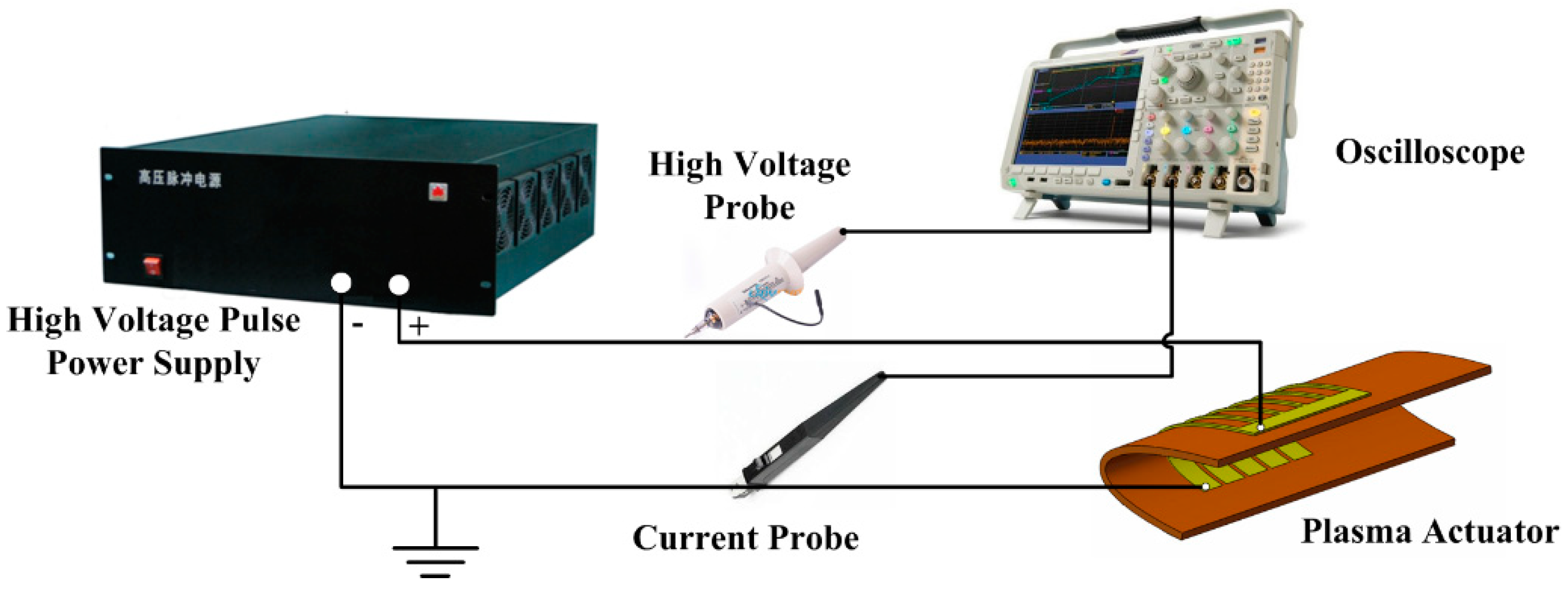
2. Experimental Setup

The experiments were performed in the Icing Research Tunnel available at Nanjing University of Aeronautics and Astronautics. The test section is 350 mm in width ×400 mm in height. Up to 120 m/s velocity airflow can be generated, and the static temperature can be adjusted, ranging from −30 °C to room temperature. Arrays of pneumatic spray nozzles are used to spray micro-sized, supercooled water droplets (ranging from 10~50 μm in size) into the airflow. Calibration was performed using a laser particle analyzer. The liquid water content (LWC) in the icing wind tunnel is controlled by the number of opened nozzles, which can be adjusted to yield a mist ranging from 0.1 to 3 g/m3. After calibration and measurement, the wind tunnel maintains good characteristics of airflow field and water droplet field.
A NACA 0012 airfoil model made of aluminum was used, as shown in Figure 3. The airfoil model has a chord length of 280 mm and spanwise length of 145 mm. The whole surface was covered with 2.5 mm thick PTFE film to prevent heat transfer between the plasma actuator and the airfoil model. The airfoil/wing model was fixed by a stainless-steel rod, oriented horizontally across the middle of the test section. The angle of attack (α) of the airfoil/wing model was set as α = −4.0 degrees during the anti-icing experiments.
The NS-DBD plasma actuator was mounted on the front part of the airfoil model, which was applied with plasma actuation. It comprises several 0.027 mm thick copper electrodes (exposed electrodes and buried electrodes) separated by 3 layers of Kapton tape as a dielectric barrier (0.24 mm). Copper electrodes are arranged along the chordwise direction. Along the span direction, there is zero overlap between the exposed and buried electrodes, the spanwise width of which are 2 mm and 10 mm respectively. From the side view of the airfoil model, the buried electrodes were distributed ranging from the airfoil leading edge to around 40 mm from the airfoil chord (at upper surface), and 20 mm from the airfoil chord (at lower surface).
The exposed electrodes of the plasma actuator were connected to a high-voltage nanosecond pulse power supply, while buried electrodes were grounded (as Figure 4 shows). The power supply used in this experiment can provide a peak-to-peak amplitude of Vp-p = 0–20 kV, and pulse frequency of fp = 1–20 kHz. The voltage rise time τ r , plateau time τ p and decaying time τ d are all adjustable, as Figure 5 shows. The voltage and current applied to the actuator are measured by a high-voltage probe (Tektronix P6015A, Tektronix, Beaverton, OR, USA) and a current probe (Tektronix P6021, Tektronix, Beaverton, OR, USA) respectively, the results of which were displayed and processed with a Tektronix DPO3054 oscilloscope.
Surface temperature is measured using a FLIR infrared (IR) imager (SC7300M, FLIR Systems, Wilsonville, OR, USA). The measurement range of the IR camera is −20 °C to 2000 °C. The surface emissivity of the Kapton is set as 0.83 [31]. The surface temperature of the exposed copper electrode was not analyzed due to its relatively lower surface emissivity. A CCD camera (Nikon D7000, Nikon Corporation, Tokyo, Japan) positioned on the side of the observation windows was used to record the dynamic ice accretion process at the front part of the airfoil model.

3. Experimental Results

3.1. Electrical Diagnostics

Experiments were conducted on the anti-icing performance of NS-DBD plasma actuator with two different discharge conditions under the same icing condition of airflow speed U = 65 m/s, ambient temperature T = −10 °C, liquid water content LWC = 0.5 g/m3, mean-volume diameter MVD = 25 μm. In this section, the effect of supercooled water droplets on the discharge morphology is illustrated and discussed.
As shown in Figure 6a, with no impingement of supercooled water droplets (U = 65 m/s, T = −10 °C, LWC = 0 g/m3), the discharge filaments are distributed homogeneously, with short plasma lengths along the edge of exposed electrodes when applied with LV-HF discharge (Vp-p = 8.6 kV, fp = 6 kHz, τ r = 200 ns, τ p = 300 ns, τ d = 200 ns), which causes a distinct dim area between the two adjacent exposed electrodes. In the case of HV-LF discharge (Vp-p = 13.6 kV, fp = 2 kHz, τ r = 200 ns, τ p = 300 ns, τ d = 200 ns), as Figure 6b shows, the discharge filament further extends towards the middle of exposed electrodes, but the dim areas still exist.
Figure 7 shows the measured voltage and current waveforms of the NS-DBD plasma actuator from two different discharge conditions. Current pulses are observed in both the rise and decay phases of the applied voltage. As the applied voltage rises, the exposed electrode acts as an anode and a positive ion sheath spread along the dielectric surface, positively charging the dielectric layer surface. In the decay process of applied voltage, the breakdown between the top electrode and the dielectric surface, which has been positively charged by the first pulse, causes the second negative current pulse [23]. The dim area here may be attributed to the effect of surface potential for two adjacent opposite discharges which contain the propagation of discharge filaments when applied with HV-LP discharge. The total power consumption of NS-DBD was computed by the temporal integration of the instantaneous power in one second:
P = 0 1 v ( t ) i ( t ) d t
The power consumption of both two discharge conditions is equal to 83 W.
Figure 6c,d show the effect of supercooled water droplets on the morphology of the two discharge conditions. It can be observed that the plasma discharge is turned to focus on several discharge channels along the electrode edge, and is relatively inhomogeneous. This phenomenon resembles the influence of ambient humidity on AC-DBD in reference [32]. Moreover, under the influence of aerodynamic force, part of the discharge channels was blocked by an unevenly distributed backward flowing water film, resulting in the experimental phenomena that discrete discharge filaments seem to slide backward with the melted backward water film.

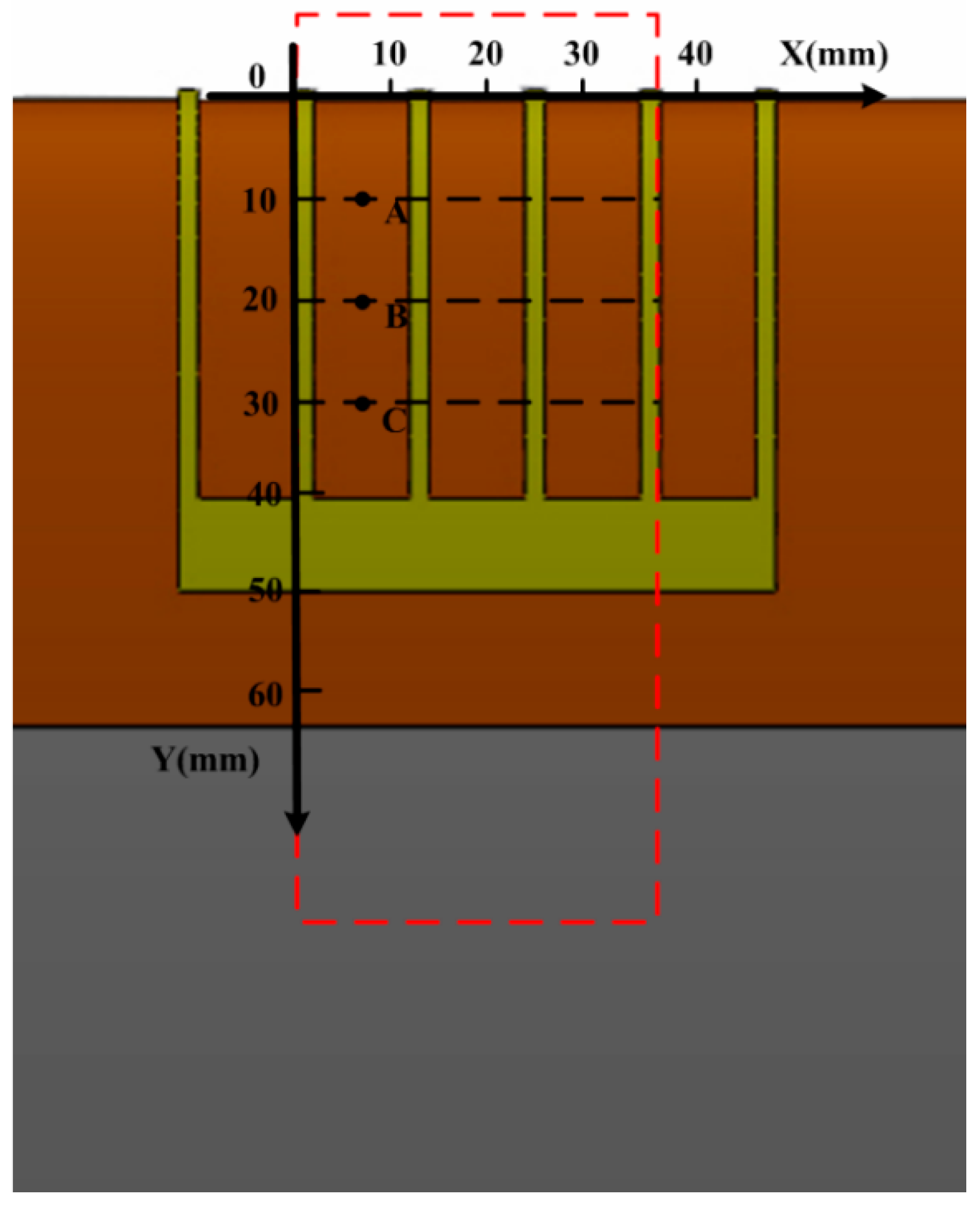
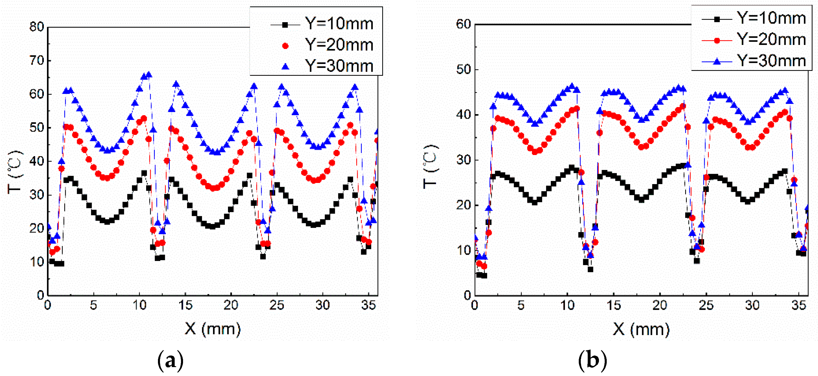
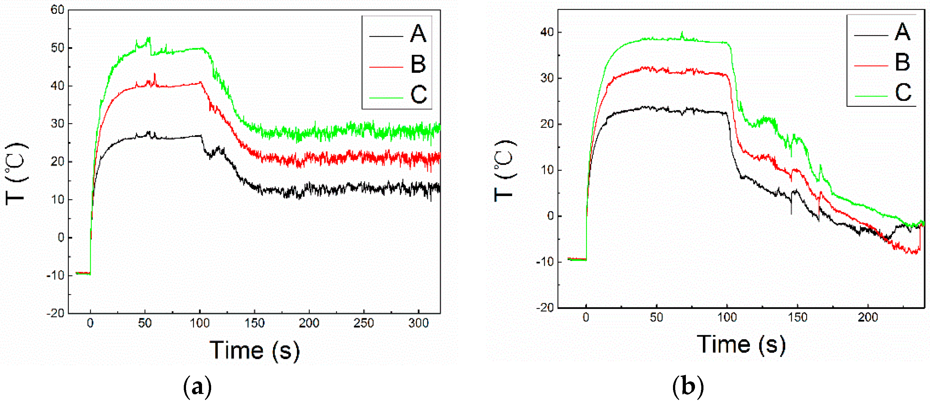
3.2. Thermal Properties

With respect to the thermal effect of dielectric barrier discharge, Rodrigues et al. [33] revealed that the gas heating of AC-DBD is caused by electron elastic collisions, rotational and vibrational excitation, ion-neutral molecule collisions, and the thermal energy transferred from electrons to neutral particles. For NS-DBD, the gas breakdown voltage is apparently higher than the quasi-static breakdown voltage due to the fast rising time, which leads to a higher reduced electric field (E/N) at the moment of gas breakdown, and more energy being obtained by charged particles. As stated in reference [34,35], the main processes of fast gas heating of NS-DBD can be classified as follow: (1) quenching of the N 2 ( C 3 u ) states by oxygen; (2) quenching of the N 2 ( B 3 g ) states by oxygen; (3) reactions involving charged particles; (4) dissociation of N2 molecules by electron impact, followed by quenching of N ( 2 D ) atoms; (5) quenching of excited O(1D) atoms by nitrogen; (6) dissociation of O2 molecules by electron impact, and (7) quenching of the excited molecules N 2 ( A 3 u + ) and N 2 ( a 1 u ) by oxygen. Zhu et al. proposed that the heating energy of gas can be divided into two parts, which can be defined as:
P h e a t = P i o n + P q c h
where P i o n means the power released through collisions between charged particles and neutrals, and P q c h is the energy released through the channel of quenching between excited molecules and neutrals or atoms [24]. Except for the gas heating, as with AC-DBD, the heating of the dielectric surface is also an essential part of the total input energy [30].
As shown in Figure 8, the measurement window of the IR thermal imaging system is in the red dotted line box. A rectangular coordinate system is established in the infrared temperature measurement area. The span direction of the airfoil model is set as the X-axis, while the chordwise direction is the Y-axis; the origin is set at the leading edge. In order to explore the thermal characteristics of the NS-DBD plasma actuator, the time variations of surface temperature under two different environments were captured: (1) room temperature (25 °C) and normal atmospheric pressure, (2) cold airflow condition of U = 65 m/s, T = −10 °C, LWC = 0 g/m3 (without turning on the spray system). The voltage waveform applied to the actuator is the same as that described in the previous section.
The NS-DBD plasma actuator quickly suffers damage at room temperature due to the high temperature of the dielectric barrier. Therefore, the surface temperature distribution of the actuator after being ignited for 10 s, as shown in Figure 9, is selected for analysis. It can be clearly seen that the temperature rise is mainly concentrated on the discharge region. With the same power consumption, the surface temperature of the HF-LV discharge is higher than that of the HV-LF discharge. The temperature peak was observed at the exposed electrode’s edge, which is consistent with the result reported in reference [36]. Moreover, it’s probably worth pointing out that disparate temperature distribution near the location of Y = 40 mm corresponds to the discharge area, which is attributed to the effect of surface potential mentioned in the previous section. Figure 10 plots the spanwise (direction of X axis) variation in temperature rise at the location of Y = 20 mm. Almost 20 °C temperature differentials are observed between two different discharge conditions near the exposed electrodes edge, while it gets relatively minor at the middle of two adjacent electrodes.
Figure 11 shows the temperature distribution over the surface of the wing model 80 s after the NS-DBD plasma actuator was switched on under conditions of cold airflow. Due to the occurrence of convection heat transfer, the surface temperature of both two discharge conditions is decreased. The spanwise (direction of X axis) temperature variation in Y = 10 mm, Y = 20 mm, Y = 30 mm are also selected, and are plotted in Figure 12. In the X direction, the temperature rise near the exposed electrode edge is the highest, which is well matched with Figure 10, when actuated at room temperature and normal atmospheric pressure. In contrast, along the chordwise (direction of Y axis), the surface temperature gradually increased within the discharge region. On the one hand, the closer to the leading edge, the more intense convective heat transfer occurs between the cold incoming flow and the airfoil [37]. On the other hand, heated gas by plasma actuation occurs at the front part flow downstream along with the cold airflow [21], which strengthens the forced convection heat transfer between heated gas and the dielectric surface in the downstream to some extent. The trend of temperature variation below the location of Y = 55 mm in Figure 12 also confirms this viewpoint; the temperature downstream the electrode edge is comparatively higher.
Beyond that, it is interesting to note that temperature change near the edge of the exposed electrode is slowly when HV-LF discharge is used, in contrast to LV-HF discharge. This can be attributed to the different heating areas of two discharge conditions. The heating of the dielectric barrier is a function of the heating of the air in the discharge volume above it [36]. As mentioned in the previous section, HV-LF discharge can promote the discharge filaments propagating towards the middle of the adjacent electrode, which leads to a larger area of discharge. Heat transfer between heated gas and the dielectric surface causes a different spanwise temperature distribution under the two discharge conditions.

3.3. Anti-Icing Performance

Anti-icing experiments using a NS-DBD plasma actuator with two different discharge conditions were conducted under the conditions of U = 65 m/s, T = −10 °C, LWC = 0.5 g/m3, MVD = 25 μm. The experiment was conducted as follows. Firstly, the wind tunnel was adjusted to the target parameters for at least an hour in order to reach a steady state. The plasma actuator was then then switched on for about 100 s to attain thermal equilibrium. Here, the moment switch on the plasma actuator is set as t = 0 s. When t = 100 s, the spray system was opened.
Figure 13 shows the dynamic anti-icing process of two different discharge conditions. As time goes on, the supercooled water droplets continuously impinge on the front part of airfoil model. When applied with HV-LF discharge, as Figure 13a shows, the supercooled water droplets hitting the discharge region are melted and run backwards. In contrast, on the other front part of the airfoil model (with no protection), ice accumulation occurs. In the case of HV-LF discharge, the appearance of ice accumulation on the airfoil surface changes to a great extent. During the discharge region, ice accretion firstly occurs between two adjacent electrodes at the leading edge of the airfoil, as shown in Figure 13b, when t = 150 s. Then, the ice area is gradually enlarged until it covers the whole leading edge. The discharge occured beneath the ice layer, as shown in Figure 13b when t = 250 s. It was not enough to melt the ice crust above, due to only a thin layer of heated air (less than 1 mm as reported in reference [21,24]) being formed. In summary, with the same total power input, the LV-HF discharge of NS-DBD plasma actuator has a better anti-icing performance than the HV-LF discharge.
To further explore the reasons for this, the surface temperature distribution during the anti-icing process was used for analysis. Figure 14 shows the time variation of the surface temperature distribution measured by thermal infrared imager (FLIR) during the anti-icing process, when applied with LV-HF discharge (Vp-p = 8.6 kV, fp = 6 kHz). It can be clearly seen that the impingement of supercooled water droplet results in a cooling of the dielectric surface. Supercooled water droplets are heated up and form a thin water film which runs backwards and develops into isolated water rivulets. The surface temperature of the water film and rivulets downstream from the heating zone kept decreasing in the backward process, which led to the heat transfer with the airfoil surface and surrounding airflow.
Figure 15 shows the time variation of the surface temperature distribution when applied with HV-LF discharge (Vp-p = 13.6 kV, fp = 2 kHz), under the same icing conditions. It can be observed that the surface temperature significantly drops after opening the spray system. When t = 150 s (50 s after opening the spray system), the temperature located at the middle of two adjacent exposed electrodes has already dropped below zero, which means that it has already frozen there. The ice surface subsequently extends. When t = 200 s, part of the surface has reached a temperature equal to that of the cold airflow (−10 °C).
To further evaluate the surface temperature variation during anti-icing process, three points A, B, and C (as Figure 8 shows) were selected. Figure 16 plots the time variations of surface temperature at the location of selected points. It can be found that the surface temperature sharply rises after igniting the plasma actuation at t = 0 s. About 25 s after that, the temperature does not change anymore (thermal equilibrium was reached). After opening the spray system when t = 100 s, the surface temperature decreases. But there are differences between the two different discharge conditions. When applied with LV-HF discharge, another thermal equilibrium was reached when t = 150 s. Compared to the former state, the surface temperature decreases. The surface temperature of point A decreased by about 23 °C, that of point B by 18 °C, and 12 °C for point C. For the case of HV-LF discharge, the surface temperature continues to decline until it is below zero.
The heating sources of the NS-DBD plasma actuator can be divided into two parts: one is the gas heating near the edge of exposed electrodes; the other is the heating of the dielectric barrier [30]. Of course, there was a convective heat transfer process between the heated gas and dielectric surface. It is worth noting that only a thin layer of air (less than 1 mm) was heated. Discharge happens at both the rising and falling edge of the applied voltage, which induces two successive ultrafast heating processes corresponding to the two current peaks which occur during one single pulse (shown in Figure 6) [23]. The temperature of air contained within the discharge volume rises several orders of magnitude in less than 1 μs [38]. After that, as Figure 17 shows, the actuator will keep “silent” for τ s i l e n t = 1 / f p τ h e a t . Correale et al. [21] studied the effect of the NS-DBD actuator on a flat plate laminar boundary layer, and found that the “hot spot” (a region of high temperature) convects downstream, becoming elongated into a streak under the condition of a 5 m/s flow. Here, the heated gas at the front part of airfoil model flows downstream along with cold airflow. In the meantime, convective heat transfer with the dielectric surface and heat conduction with cold airflow occurs, which means that the heat is quickly dissipated.
NS-DBD plasma actuation seems to wrap a layer of hot air over the surface of the airfoil model; each pulse individually contributes to the thermal expansion. The supercooled water droplets need to pass through a hot thin air film before they hit the wing surface. Part of input energy of the plasma discharge is directly injected into the heated air and used to warm the supercooled water droplets. Higher voltage induces a relatively larger heating area, and single pulse energy increased as well. When a HV-LP discharge occurred, single pulse energy increased, and more energy was used for gas heat during one single pulse, while it was quickly dissipated due to the long “silent” period. It is suggested that there is a threshold frequency, corresponding to the voltage amplitude of the electric actuation signal and the incoming flow condition, to achieve effective anti-icing performance.
Apart from thermal effects, aerodynamic effects should also be taken into consideration. Previous study has revealed that the mixture of gas and supercooled water droplets is in a non-equilibrium state. When a shock wave propagates in such a mixture, it would cause the relaxation processes of momentum-, heat- and mass transfer [39,40]. Pressure waves induced by ultrafast gas heating of the NS-DBD plasma actuator may also affect the movement trajectory of supercooled water droplets, and then influence the water collection coefficient. In addition, it has also been revealed that the plasma treatment can be used for the surface modification of materials [41]. Wei et al. [42] founded that the surface wettability of polypropylene fibers was significantly changed through plasma treatment. Here, NS-DBD can modify the physical and chemical features of dielectric material, which may also affect the icing process when supercooled water droplets impinge upon it [43].

4. Conclusions

The anti-icing performance of a NS-DBD plasma actuator has been experimentally investigated in this study. Two typical discharge conditions were selected to evaluate the anti-icing performance of NS-DBD plasma actuator, mainly to clarify the effect of pulse frequency and the voltage amplitude of the electric excitation signal on anti-icing performance. The first was a HV-LF discharge, corresponding to discharge under a higher voltage amplitude with lower pulse frequency; the second was LV-HF discharge, corresponding to discharge under lower voltage amplitude with higher pulse frequency.
It was found that the surface temperature rise was mainly concentrated on the discharge area, and the peak value is located at the exposed electrode edges. LV-HF discharge can induce a higher surface temperature rise that that of a HV-LF discharge for the selected discharge conditions in this experiment. However, HV-LF discharge can further extend the discharge area. The heating source of NS-DBD plasma actuation can be divided into two parts: the gas heating near the edge of exposed electrodes, and the heating of the dielectric barrier. NS-DBD plasma actuation seems to wrap a layer of hot air film over the surface of the airfoil model, and each pulse individually contributes to the thermal expansion. Heated gas by plasma actuation at the front part flows downstream along with the cold airflow, strengthening the forced convection heat transfer between heated gas and dielectric surface in the downstream to some extent. The supercooled water droplets need to pass through a hot thin air film before they hit the wing surface. Part of input energy of the plasma discharge is directly injected into the heated air and used to warm the supercooled water droplets.
With respect to the anti-icing effect, the LV-HF discharge shows a better performance than the HV-LF discharge under the same ice conditions and with the same power consumption. In view of pulse duration and duty circle, combined with heat dissipation, it is suggested that there is a threshold frequency corresponding to the voltage amplitude of electric actuation signal and the incoming flow condition by which effective anti-icing performance may be achieved.

Author Contributions

Experiments design, J.C. and B.W.; Formal Analysis, J.C. and G.Z.; Paper Writing, J.C.; Supervision, Y.W. and H.L.; Validation, L.X. and M.T.

Funding

This research was funded by the National Natural Science Foundation of China (NSFC), under the following grant numbers (Nos. 51336011, 51407197).

Conflicts of Interest

The authors declare no conflict of interest.

References

  1. Lynch, F.; Khodadoust, A. Erratum to “Effects of ice accretions on aircraft aerodynamics”: [Prog. Aerosp. Sci. 37 (2001) 669–767]. Prog. Aerosp. Sci. 2002, 38, 273–274. [Google Scholar] [CrossRef]
  2. Calay, R.K.; Holdoacute, A.E.; Mayman, P.; Lun, I. Experimental Simulation of Runback Ice. J. Aircr. 2015, 34, 206–212. [Google Scholar] [CrossRef]
  3. Aircraft Icing. AOPA Air Satety Foundation [EB/OL]. Available online: http://www.asf.org (accessed on 4 September 2009).
  4. Thomas, S.K.; Cassoni, R.P.; Macarthur, C.D. Aircraft anti-icing and de-icing techniques and modeling. J. Aircr. 1996, 33, 841–854. [Google Scholar] [CrossRef]
  5. Kind, R.J.; Potapczuk, M.G.; Feo, A.; Golia, C.; Shah, A.D. Experimental and computational simulation of in-flight icing phenomena. Prog. Aerosp. Sci. 1998, 34, 257–345. [Google Scholar] [CrossRef]
  6. Zumwalt, G.W.; Schrag, R.L.; Bernhart, W.D.; Friedberg, R.A. Electro-Impulse De-Icing Testing Analysis and Design; NASA-CR-4175, E-4279, NAS 1.26:4175; NASA: Washington, DC, USA, 1988.
  7. Papadakis, M.; Wong, S.H.; Yeong, H.W.; Wong, S.C.; Vu, G. Icing Tunnel Experiments with a Hot Air Anti-Icing System. In Proceedings of the 46th AIAA Aerospace Sciences Meeting and Exhibit, Reno, NV, USA, 7–10 January 2008. [Google Scholar]
  8. D’Avirro, J.; Chaput, M. Optimizing the Use of Aircraft Deicing and Anti-Icing Fluids. ACRP Rep. 2011. [Google Scholar] [CrossRef]
  9. Pauw, D.D.; Dolatabadi, A. Effect of Superhydrophobic Coating on the Anti-Icing and Deicing of an Airfoil. J. Aircr. 2016, 54, 1–10. [Google Scholar]
  10. Zumwalt, G. Icing tunnel tests of Electro-Impulse De-Icing of an Engine Inlet and High-speed Wings. AIAA J. 2013, 85, 466. [Google Scholar]
  11. Zhao, Z.; Chen, H.; Liu, X.; Liu, H.; Zhang, D. Development of High-efficient Synthetic Electric Heating Coating for Anti-icing/de-icing. Surf. Coat. Technol. 2018, 349, 340–346. [Google Scholar] [CrossRef]
  12. Pourbagian, M.; Habashi, W.G. Surrogate-Based Optimization of Electrothermal Wing Anti-Icing Systems. J. Aircr. 2013, 50, 1555–1563. [Google Scholar] [CrossRef]
  13. Broeren, A.P.; Riley, J.T. Scaling of Lift Degradation Due to Anti-Icing Fluids. J. Aircr. 2013, 50, 1886–1895. [Google Scholar] [CrossRef]
  14. Zhao, Y.; Chang, S.; Yang, B.; Zhang, W.; Leng, M. Experimental study on the thermal performance of loop heat pipe for the aircraft anti-icing system. Int. J. Heat Mass Trans. 2017, 111, 795–803. [Google Scholar] [CrossRef]
  15. Moreau, E. Airflow control by non-thermal plasma actuators. J. Phys. D Appl. Phys. 2007, 40, 605–636. [Google Scholar] [CrossRef]
  16. Corke, T.C.; Enloe, C.L.; Wilkinson, S.P. Dielectric Barrier Discharge Plasma Actuators for Flow Control. Annu. Rev. Fluid Mech. 2009, 42, 505–529. [Google Scholar] [CrossRef]
  17. Zhao, G.Y.; Li, Y.H.; Liang, H.; Han, M.H.; Hua, W.Z. Control of vortex on a non-slender delta wing by a nanosecond pulse surface dielectric barrier discharge. Exp. Fluids 2015, 56, 1864. [Google Scholar] [CrossRef]
  18. Little, J.; Takshima, K.; Nishihara, M.; Adamovich, I.; Mo, S. Separation Control with Nanosecond-Pulse-Driven Dielectric Barrier Discharge Plasma Actuators. AIAA J. 2012, 50, 350–365. [Google Scholar] [CrossRef] [Green Version]
  19. Starikovskii, A.Y.; Nikipelov, A.A.; Nudnova, M.M.; Roupassov, D.V. SDBD plasma actuator with nanosecond pulse-periodic discharge. Plasma Sour. Sci. Technol. 2009, 18, 034015. [Google Scholar] [CrossRef]
  20. Takashima, K.; Zuzeek, Y.; Lempert, W.; Adamovich, I. Characterization of Surface Dielectric Barrier Discharge Plasma Sustained by Repetitive Nanosecond Pulses. Plasma Sour. Sci. Technol. 2011, 20, 055009. [Google Scholar] [CrossRef]
  21. Correale, G.; Michelis, T.; Ragni, D.; Kotsonis, M.; Scarano, F. Nanosecond-pulsed plasma actuation in quiescent air and laminar boundary layer. J. Phys. D Appl. Phys. 2014, 47, 105201. [Google Scholar] [CrossRef]
  22. Benard, N.; Zouzou, N.; Claverie, A.; Sotton, J.; Moreau, E. Optical visualization and electrical characterization of fast-rising pulsed dielectric barrier discharge for airflow control applications. J. Appl. Phys. 2012, 111, 47. [Google Scholar] [CrossRef]
  23. Unfer, T.; Boeuf, J.P. Modelling of a nanosecond surface discharge actuator. J. Phys. D Appl. Phys. 2009, 42, 194017. [Google Scholar] [CrossRef]
  24. Zhu, Y.; Wu, Y.; Cui, W.; Li, Y.; Jia, M. Modelling of plasma aerodynamic actuation driven by nanosecond SDBD discharge. J. Phys. D Appl. Phys. 2013, 46, 355205. [Google Scholar] [CrossRef]
  25. Wu, Y.; Li, Y.; Jia, M.; Song, H.; Liang, H. Optical emission characteristics of surface nanosecond pulsed dielectric barrier discharge plasma. J. Appl. Phys. 2013, 113, 505. [Google Scholar] [CrossRef]
  26. Jiang, H.; Shao, T.; Zhang, C.; Li, W.; Yan, P. Experimental study of Q-V Lissajous figures in nanosecond-pulse surface discharges. IEEE Trans. Dielectr. Electr. Insul. 2013, 20, 1101–1111. [Google Scholar] [CrossRef]
  27. Cai, J.; Tian, Y.; Meng, X.; Han, X.; Zhang, D. An experimental study of icing control using DBD plasma actuator. Exp. Fluids 2017, 58, 102. [Google Scholar] [CrossRef]
  28. Liu, Y.; Kolbakir, C.; Hu, H. A comparison study on the thermal effects in DBD plasma actuation and electrical heating for aircraft icing mitigation. Int. J. Heat Mass Trans. 2018, 124, 319–330. [Google Scholar] [CrossRef]
  29. Jia, Y.; Sang, W.; Cai, Y. Numerical Analysis of Anti-Icing Property of NSDBD Plasma Actuator on Airfoil. In Proceedings of the AIAA Atmospheric and Space Environments Conference, Denver, CO, USA, 5–9 June 2017. [Google Scholar]
  30. Van Den, B.J. De-Icing Using ns-DBD Plasma Actuators. Master’s Thesis, Delft University of Technology, Delft, The Netherlands, 2016. [Google Scholar]
  31. Bian, D.L.; Wu, Y.; Jia, M. Characterization of surface dielectric barrier discharge (SDBD) based on PI/Al2O3 nanocomposite. Plasma Process. Polym. 2018, e1700236. [Google Scholar] [CrossRef]
  32. Wicks, M.; Thomas, F.O. Effect of Relative Humidity on Dielectric Barrier Discharge Plasma Actuator Body Force. AIAA J. 2015, 53, 1–4. [Google Scholar] [CrossRef]
  33. Rodrigues, F.; Pascoa, J.; Trancossi, M. Heat generation mechanisms of DBD plasma actuators. Exp. Therm. Fluid Sci. 2018, 90, 55–65. [Google Scholar] [CrossRef]
  34. Popov, N.A. Fast gas heating in a nitrogen-oxygen discharge plasma: I. Kinetic mechanism. J. Phys. D Appl. Phys. 2011, 44, 285201. [Google Scholar] [CrossRef]
  35. Poggie, J.; Bisek, N.; Adamovich, I.; Nishihara, M. Numerical Simulation of Nanosecond-Pulse Electrical Discharges. Plasma Sour. Sci. Technol. 2012, 22, 015001. [Google Scholar] [CrossRef]
  36. Tirumala, R.; Benard, N.; Moreau, E.; Fenot, M.; Lalizel, G. Temperature characterization of dielectric barrier discharge actuators: Influence of electrical and geometric parameters. J. Phys. D Appl. Phys. 2014, 47, 255203. [Google Scholar] [CrossRef]
  37. Liu, Y.; Hu, H. An Experimental Investigation on the Convective Heat Transfer Process over an Ice Roughened Airfoil. In Proceedings of the 53rd AIAA Aerospace Sciences Meeting, Kissimmee, FL, USA, 5–9 January 2015. [Google Scholar]
  38. Zheng, J.G.; Li, J.; Zhao, Z.J.; Cui, Y.D.; Khoo, B.C. Numerical Study of Nanosecond Pulsed Plasma Actuator in Laminar Flat Plate Boundary Layer. Commun. Comput. Phys. 2016, 20, 1424–1442. [Google Scholar] [CrossRef]
  39. Thomas, G.O. On the Conditions Required for Explosion Mitigation by Water Sprays. Process Saf. Environ. Protect. 2000, 78, 339–354. [Google Scholar] [CrossRef] [Green Version]
  40. Goossens, H.W.J.; Cleijne, J.W.; Smolders, H.J.; Dongen, M.E.H.V. Shock wave induced evaporation of water droplets in a gas-droplet mixture. Exp. Fluids 1988, 6, 561–568. [Google Scholar] [CrossRef]
  41. Wei, Q.F. Surface characterization of plasma-treated polypropylene fibers. Mater. Charact. 2004, 52, 231–235. [Google Scholar] [CrossRef]
  42. Wei, Q.; Li, Q.; Wang, X.; Huang, F.; Gao, W. Dynamic water adsorption behaviour of plasma-treated polypropylene nonwovens. Polym. Test. 2006, 25, 717–722. [Google Scholar] [CrossRef]
  43. Starostin, A.; Valtsifer, V.; Barkay, Z.; Legchenkova, I.; Danchuk, V.; Bormashenko, E. Drop-Wise and Film-Wise Water Condensation Processes Occurring on Metallic Micro-Scaled Surfaces. Appl. Surf. Sci. 2018, 444, 604–609. [Google Scholar] [CrossRef]
Figure 1. Sketch of a DBD plasma actuator.
Applsci 08 01889 g001
Figure 2. Characteristic schlieren images of the pressure wave induced by NS-DBD from two observation directions [20].
Applsci 08 01889 g002
Figure 3. A NACA 0012 airfoil model.
Applsci 08 01889 g003
Figure 4. Schematic illustration of NS-DBD plasma actuator.
Applsci 08 01889 g004
Figure 5. Sketch of a positive nanosecond voltage pulse with rise time τ r , plateau time τ p and decay time τ d .
Applsci 08 01889 g005
Figure 6. Discharge morphology of NS-DBD: (a) LV-HF discharge without impingement from supercooled water droplets; (b) HV-LF discharge without impingement from supercooled water droplets; (c) LV-HF discharge with impingement from supercooled water droplets; (d) LV-HF discharge with impingement from supercooled water droplets.
Applsci 08 01889 g006
Figure 7. Voltage-current waveforms of NS-DBD with two different discharge conditions: (a) LV-HF discharge; (b) HV-LF discharge.
Applsci 08 01889 g007
Figure 8. Measurement window of the IR thermal imaging system.
Applsci 08 01889 g008
Figure 9. The surface temperature distribution 10 s after NS-DBD plasma actuator was switched on at room temperature (25 °C) and normal atmospheric pressure: (a) LV-HF discharge; (b) HV-LF discharge.
Applsci 08 01889 g009
Figure 10. The spanwise (direction of X axis) variation in temperature rise at the location of Y = 20 mm.
Applsci 08 01889 g010
Figure 11. The surface temperature distribution 80 s after NS-DBD plasma actuator was switched on under the condition of U = 65 m/s, T = −10 °C, LWC = 0 g/m3: (a) LV-HF discharge; (b) HV-LF discharge.
Applsci 08 01889 g011
Figure 12. The spanwise (direction of X axis) temperature variation of Y = 10 mm, Y = 20 mm, Y = 30 mm: (a) LV-HF discharge; (b) HV-LF discharge.
Applsci 08 01889 g012
Figure 13. Dynamic anti-icing process of NS-DBD plasma actuator: (a) LV-HF discharge; (b) HV-LF discharge.
Applsci 08 01889 g013
Figure 14. Time variation of the surface temperature distribution during the anti-icing process when applied with LV-HF discharge.
Applsci 08 01889 g014
Figure 15. Time variation of the surface temperature distribution during the anti-icing process when applied with HV-LF discharge.
Applsci 08 01889 g015
Figure 16. Time variations of surface temperature at the location of selected points: (a) LV-HF discharge; (b) HV-LF discharge.
Applsci 08 01889 g016
Figure 17. Time series diagram of NS-DBD discharge.
Applsci 08 01889 g017

