Seismic Behaviors of Concrete Beams Reinforced with Steel-FRP Composite Bars under Quasi-Static Loading


1
Institute of Structural Engineering (College of Architectural Engineering), Nanjing Institute of Technology, Nanjing 211167, China
2
Nanjing Chixia Develpopment Co. Ltd., Nanjing 210037, China
3
Key Laboratory of Concrete and Prestressed Concrete Structures of the Ministry of Education, Southeast University, Nanjing 210096, China
4
College of Civil Engineering, AnHui Jianzhu University, Hefei 230601, China
*
Author to whom correspondence should be addressed.
Appl. Sci. 2018, 8(10), 1913; https://doi.org/10.3390/app8101913
Submission received: 12 September 2018
/
Revised: 2 October 2018
/
Accepted: 8 October 2018
/
Published: 14 October 2018
(This article belongs to the Special Issue Soft Computing Techniques in Structural Engineering and Materials)
Abstract
:Steel-fiber reinforced polymer (FRP) composite bar (SFCB) is a new composite material with good corrosion resistance and designable post-yield stiffness. Substitution of steel bar with SFCB can greatly increase the durability and ultimate capacity associated with seismic performance. First, the method and main results of the experiment are briefly introduced, then a simplified constitutive model of composite bar material was applied to simulate the seismic behaviors of the concrete beams reinforced with SFCBs by fiber element modeling. The simulation results were found to be in good agreement with test results, indicating that the finite element model is reasonable and accurate in simulating the seismic behaviors of beams reinforced with SFCB. Based on the numerical simulation method, a parametric study was then conducted. The main variable parameters were the FRP type in composite bars (i.e., basalt, carbon FRP and E-glass FRP), the concrete strength, basalt FRP (BFRP) content in SFCBs and shear span ratio. Seismic behaviors such as load-displacement pushover curves, seismic ultimate capacity and its corresponding drift ratio of the SFCBs reinforced concrete beams were also evaluated. The results showed that (1) the fiber type of the composite bar had a great impact on the mechanical properties of the beam, among which the beam reinforced with BFRP composite bar has higher seismic ultimate capacity and better ductility. With the increase of the fiber bundle in the composite bar, the post-yield stiffness and ultimate capacity of the component increase and the ductility is better; (2) at the pre-yield stage, concrete strength has little influence on the seismic performance of concrete beams while after yielding, the seismic ultimate capacity and post-yielding stiffness of specimens increased slowly with the increase in concrete strength, however, the ductility was reduced accordingly; (3) as the shear span ratio of beams increased from 3.5 to 5.5, the seismic ultimate capacity decreased gradually while the ultimate drift ratio increased by more than 50%. Through judicious setting of the fiber content and shear span ratio of the composite bar reinforced concrete beam, concrete beams reinforced with composite bars can have good ductility while maintaining high seismic ultimate capacity.
1. Introduction
Steel is one of the most widely used materials in construction engineering. However, in severe environments (strong acid and alkali, seaports and chemical structures, etc.), and after 10–15 years, structures generally show serious cracks along the rebar direction caused by steel corrosion. This soon evolves into serious damage if effective measures are not taken. To enhance the anti-corrosion properties of steel bars, various techniques have been proposed. Fiber reinforced polymer (FRP) is a non-metal material that has evolved to an effective substitution for steel rebar in severe environments. Furthermore, FRPs can be suitable for use in extreme conditions such as fire or blast loading [1,2]. Because of the highly desirable properties of FRP, such as high strength, light weight and high anti-corrosion, the application of FRP as reinforcement in concrete structures has been growing rapidly [3,4,5,6]. A potential application of FRP reinforcement is in reinforced concrete (RC) frames. However, due to FRP’s predominantly elastic behavior, FRP-RC members exhibit low ductility and energy dissipation, thus restricting its application in construction [7,8]. In recent years, it has been reported that RC members reinforced by hybrid conventional steel bars and FRP bars can improve their seismic performance [9,10,11].
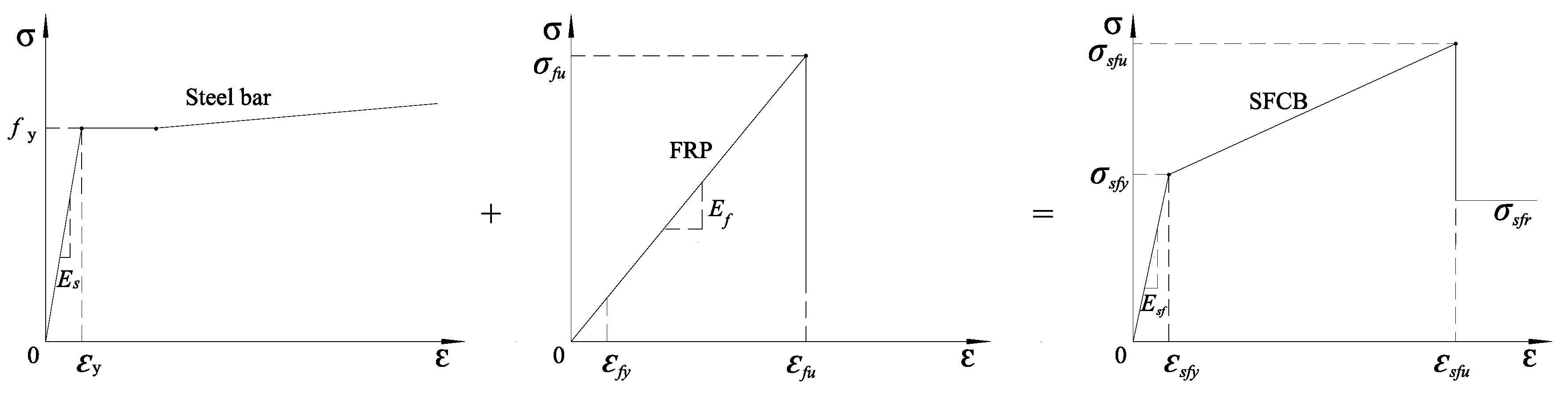
A hybrid rod made with FRP skin over a steel core was first proposed by Nanni et al. [12] to achieve good anti-corrosion performance for concrete beams, where the FRP skin is made of braided epoxy-impregnated aramid or vinylon fiber. Combining the advantages of FRP and steel bar, the new composite bar is expected to have high strength, high elastic modulus, good ductility and anti-corrosion properties. The factory-produced steel-FRP composite bar (SFCB) was proposed by Wu et al. [13]. According to the composition rule, the stress-strain relationship of the SFCB can be appropriately simulated as the linear superposition of steel reinforcement and FRP. The schematic stress-strain relationship of this composite bar can be seen in Figure 1.
Suppose that the outside fiber has fine interface bonding and harmonious deformation with the inner steel bar in the process of loading, that is, they have the same strain in one section. The stress-strain relationship of a SFCB under uniaxial tensile loading can be accurately simulated by the composite superposition principle [14] using Equation (1).
where, σsf and εsf are tensile stress and strain of composite bar, respectively; Ef and Af are elastic modulus and cross-sectional area of the composite bar’s outer FRP, respectively; and A is the total cross-sectional area of the composite bar.
The stress-strain relation of compression is described as Equation (2).
where, σ’sf and ε’sf are compressive stress and strain of composite bar, while f’y and E’s are compressive yield stress and elastic modulus of inner steel bar.
By comparing test curves of SFCB specimens and conventional steel bar specimens, it was found that the residual deformation of SFCB was less than that of a conventional steel bar when unloading from peak strain after yielding. Further, the stress-strain relationship of SFCB under a cyclic tensile load is provided through monotonic tensile and reciprocating tensile tests according to composition rule, providing the inner steel bar has same deformation with the composite bar.
Previous studies have indicated that compared with conventional steel bar, steel-fiber composite bar has good anti-corrosion performance and designable post-yield stiffness. When the conventional RC member encounters seismic excitation, it is difficult to achieve stable post-yield stiffness due to the large plastic deformation of the steel bar. For the purpose of achieving the seismic fortification goals of “reparable after a medium earthquake” and “collapse after a major earthquake”, SFCB is considered to be the ideal replacement for steel bar in concrete members for structural design and application. Up to now, many experimental studies have been conducted on the mechanical performance of the SFCB [15] and concrete members reinforced with SFCB, including simply supported beams [16], columns [17], column-beam connections [18], and the bonding behavior of SFCB with concrete by pull-out performance [19]. To date, the material has been investigated primarily through experiments, while few effective numerical simulations have been conducted to study the seismic behaviors of the frame beam members [20]. It is essential to explore a simulation framework due to the limited number of experiments.
RC frame beams are an important supporting member of frame structure. They also play a crucial role in resisting horizontal seismic action. Frame beams not only support bending moments, but also support large shear forces and small axial forces, and they can be viewed as a special form of column without axial force. Meanwhile, they have their own characteristics, such as a small cracking load and a complex nonlinear deformation and failure mode after plastic hinge forms, etc. Since the increase in span and the load case has become more and more complex, the design principle of “strong column weak beam” for ordinary RC frame structures has gradually evolved into “strong column and beam”. At present, the research on the seismic performance of components is mainly focused on columns, and less on beams. In this paper, the seismic performance test of concrete beams reinforced with SFCB was introduced. After that, a numerical simulation study was carried out by the finite element software OpenSees. The simulation results were compared with the test results for specimens with the same geometric and mechanical properties as the numerical models. Then, parametric studies were carried out to analyze the seismic behaviors of the concrete beams reinforced with SFCBs. The main variable parameters were the FRP type in composite bars (i.e., basalt, carbon FRP or E-glass FRP), the concrete strength, the steel/FRP ratio of the SFCB and shear span ratio. Seismic behaviors such as skeleton curves, seismic ultimate capacity and the corresponding drift ratio (defined as ultimate drift ratio, its value is equal to the beam’s top horizontal displacement at the peak load divided by the beam’s length) of the SFCB reinforced concrete beams were also evaluated.
2. Experimental Study of Concrete Beams Reinforced with Composite Bars
2.1. Material Properties
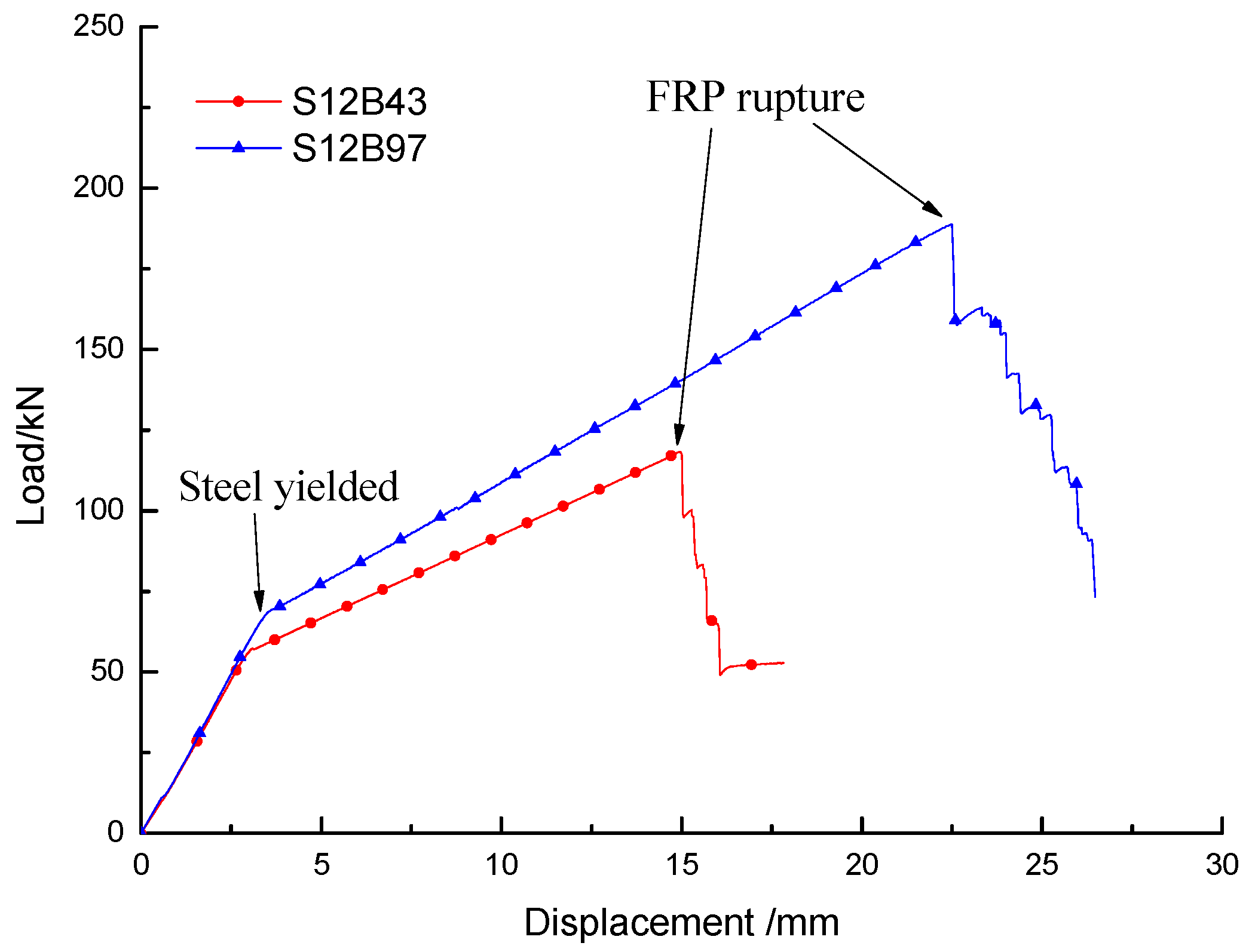
The concrete strength grade of specimens was C30. The tested unconfined compressive strength of cubic concrete (150 × 150 × 150 mm) at 28 days is 31.6 MPa; the corresponding cylinder compressive strength is 26.2 MPa. The stirrup and the inner reinforcement were all HRB400 (China-made steel bar), and the diameter of the inner reinforcement was 12 mm. The types of longitudinal bars were divided into S12B43 and S12B97 according to the number of outer fibers (Figure 2). The designation “S12B43” means that the composite bar is made of a steel bar with a 12-mm diameter longitudinally wrapped by 43 bundles of 2400-tex basalt fibers, where “tex” represents the weight of a single fiber bundle per kilometer. The test device and failure modes are shown in Figure 3, and the tensile load-displacement curve is shown in Figure 4. The mechanical properties of conventional reinforcement bars and composite bars are shown in Table 1.
2.2. Experimental Program
One of the main objectives of this experiment research was to assess the quasi-static (including monotonic and cyclic) response of concrete beams reinforced with steel-FRP composite bars. According to the experimental research of concrete beams reinforced with composite bar, two beam specimens were tested to meet the objectives of this study. The S12B43 beam was subjected to horizontal monotonic load, while the S12B97 beam was subjected to horizontal low-cyclic load (Figure 5). The loading device is shown in Figure 6.
The reinforcement is designed according to the principle of “strong shearing and weak bending”. As the expected failure mode of the beam is bending failure, in the experiment, the height of the test beam was 1200 mm (length of beam) with a shear-span ratio of 4, as shown in Figure 7. For the S12B97 specimen, the loading program manipulated both the applied force and the displacement. Before the concrete beam yielded, loading was added by force control. Each step of the load cycled once and had a 10-kN gradient. After the concrete beam yielded, loading was established through measured lateral displacement of the column cap at multiple intervals of the column yield displacement. Each step was cycled three times until the specimen failed.
2.3. Test Result
The crack point, yield point, peak load point and failure point exist for each specimen in the test. The experimental phenomena and results are described below.
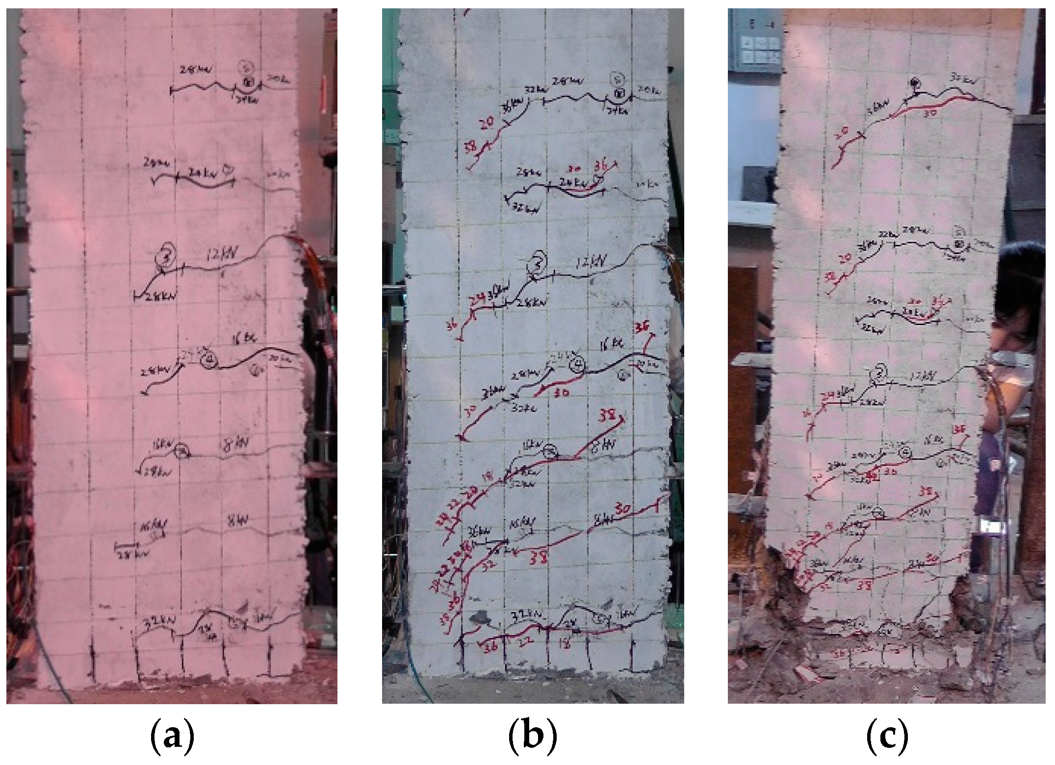
The S12B43 beam was loaded by horizontal monotonic loading. When the load reaches 8 kN, two horizontal cracks appeared at the height of 175 mm and 270 mm from the root, indicating that the specimen had entered the cracking stage, as shown by No. 1 and No. 2 cracks in Figure 8a. At this time, the slope of the load-displacement curve decreased slightly. When the horizontal load reached 32 kN, the composite bar on the tensile side began to yield, indicating that the specimen was entering the yield stage. At this time, there is an obvious turning point on the load-displacement curve, and the yield displacement reached 9.8 mm, as shown in Figure 8b. The loading mode was changed from force control to displacement control. With the increase in displacement, the crack developed into an inclined crack from the horizontal direction and extended downward, with the crack bifurcation and peeling of the protective layer of concrete at the root of the compression zone. The width of the crack at the root was up to 1 mm. When the control displacement reached 52 mm, the outer fiber of the composite bar broke one after another. The sound of the fracture became louder and louder. When the displacement was loaded to 57~58 mm, most of the fiber at the end of the specimen ruptured, and the tensile longitudinal bar made a “boom”, indicating the specimen failure. At the moment the fiber fractured, the load dropped sharply. When the displacement continued to increase, the compression side concrete was damaged more and more seriously, and the crack width of the tensile side concrete widened rapidly, until the block fell off, and the loading stopped when the specimen was seriously damaged. The crack pattern and final failure mode of the specimen are shown in Figure 8c.
The S12B97 beam was subjected to horizontal reversed cyclic loading. When the load reached 10 kN, small horizontal cracks began to appear at the height of 150 mm, 200 mm and 300 mm from the root of the specimen, indicating that the specimen had entered the cracking stage, as shown in Figure 9a. When the horizontal load reached −30 kN, the tensile strain of the longitudinal bar reached 0.0022, and the inner steel bar started to yield, indicating that the component had entered the yield stage, as shown in Figure 9b. Before yielding, the load-displacement curve of specimen was basically linear. When the displacement reached 32 mm, the concrete protective layer of the compression side peeled, and there were many diagonal and horizontal cracks between the initial cracks. In the process of the displacement reaching 64 mm, outer fiber in the composite bars was fractured and it made a series of clear clicking sounds during loading. The concrete in the compressive zone peeled off and the load reached the ultimate seismic capacity. Then, as the displacement continued to increase, the concrete in the base of the specimen became crunchy and started to fall off in blocks. The specimen was obviously severely damaged, with the load dropping sharply.
As observed in the above failure process in the experiment, the lateral load versus top displacement curves of the two specimens are shown in Figure 10. Several points representing the key response stages are identified on the curves, including first cracking of concrete, first yielding of tension reinforcement, the rupture of outer BFRP in SFCB and the spalling of concrete in the compression zone. It can be seen from Figure 10a that the stiffness of specimen S12B43 decreases significantly after the section cracks. This may be attributed to the local drop in the stiffness that takes place at the location of the cracked section due to formation of long cracks in conjunction with the low value of the modulus of elasticity of the reinforcing bars (Esf) with regards to the modulus of elasticity of the used concrete (Ec). Due to the difference in mechanical properties of composite bar and conventional steel bar, the failure process and load-displacement curve of specimens are also different. This is mainly reflected in the post-yielding stage of the longitudinal bar. When the inner steel bar yields, the stress of the steel bar hardly increases and the deformation obviously increases. At this time, the high-strength characteristics of the outer BFRP gradually come into play. As the top displacement increases in the test, the load of the specimen increases significantly. Moreover, the increase of load is directly proportional to the fiber content. When the outer fiber breaks, the specimen reaches the maximum capacity with spalling of concrete in the compression zone. Subsequently, the load dropped significantly and the specimens failed. Compared with the ordinary RC specimen, the most obvious difference is that the ratio of maximum load to yield load of SFCB specimens is greater than that of the RC specimen, and this is designable and can be changed by the fiber content.
3. Numerical Modeling of Concrete Beams Reinforced with SFCB
3.1. Fiber Element Modeling Method
The analyses were conducted using Open System for Earthquake Engineering Simulation (OpenSees) software [21]. This software has advanced capabilities for modeling and analyzing the nonlinear response of systems using a wide range of material models, elements, and solution algorithms. OpenSees software is stable and suitable for simulating beams under monotonic or cyclic lateral loading. This software has an important feature that includes many materials in it. Furthermore, fiber-based finite element analysis is the most economical and accurate method for modeling the nonlinear global response of RC structures [22,23,24]. In the fiber-based finite element method, the element sections are discretized by uniaxial fiber elements, to which corresponding material constitutive laws are assigned in the form of uniaxial stress-strain relationships. The fibers shorten or elongate so that plane sections remain plane after deformation.
Each frame beam was modeled as one nonlinear Euler Bernoulli beam–column element with five integration points, which was discretized by uniaxial fiber elements. the element model based on the displacement method, namely the “Disp Beamcolumn element” model in OpenSees. The element allows stiffness change along the length direction of the element, it obtains resistance and the top displacement of components through the integration of the node displacement. Considering the test situation, the component end is set as a fixed end, regardless of the torsional deformation of the component, and the specific model setting is shown in Figure 11. Figure 11a shows the fiber element model of the beam. Figure 11b presents a discretized fiber section for a typical strengthened beam, including concrete fibers, steel fibers, and composite bar fibers, which were assigned with corresponding measured material properties. The lateral load was applied using the imposed displacement, and P-Delta effects were included in the analyses. Three algorithms, namely Newton Raphson algorithm, Broyden algorithm and Newton-Line-Search algorithm were adopted successively for nonlinear solution; and the tolerance was defined as 1.0 × 10⁻⁶ in OpenSees.
3.2. Stress-Strain Relationships
3.2.1. Concrete
Concrete02 material in OpenSees is adopted for both the confined and unconfined concrete in this paper. The modified Kent-Park model [25] is adopted as the compressive portion of the backbone curve, which maintains a balance between simplicity and accuracy and examines the confinement effect of stirrups by modifying the peak stress-strain point and softening a portion of the concrete compressive backbone. The concrete parameter is realized by defining the compressive strength f’c, the ratio λ between unloading slope at εcu and initial slope Eo, compressive strain (εco = 2f’c/Eo), crushing strength (fcu = 0.2f’c), crushing strain (εcu = 5εco), and tensile strength ft, as shown in Figure 12.
The cylinder strength of the test is used to define the cover concrete fibers. As confined concrete, the compressive strength is taken as 1.3 times that of the unconfined cover concrete, based on the transverse reinforcement ratio of the concrete beam. The corresponding values of concrete parameters obtained from the calculation formula of the Kent-Park model are shown in Table 2.
3.2.2. Reinforcing Steel
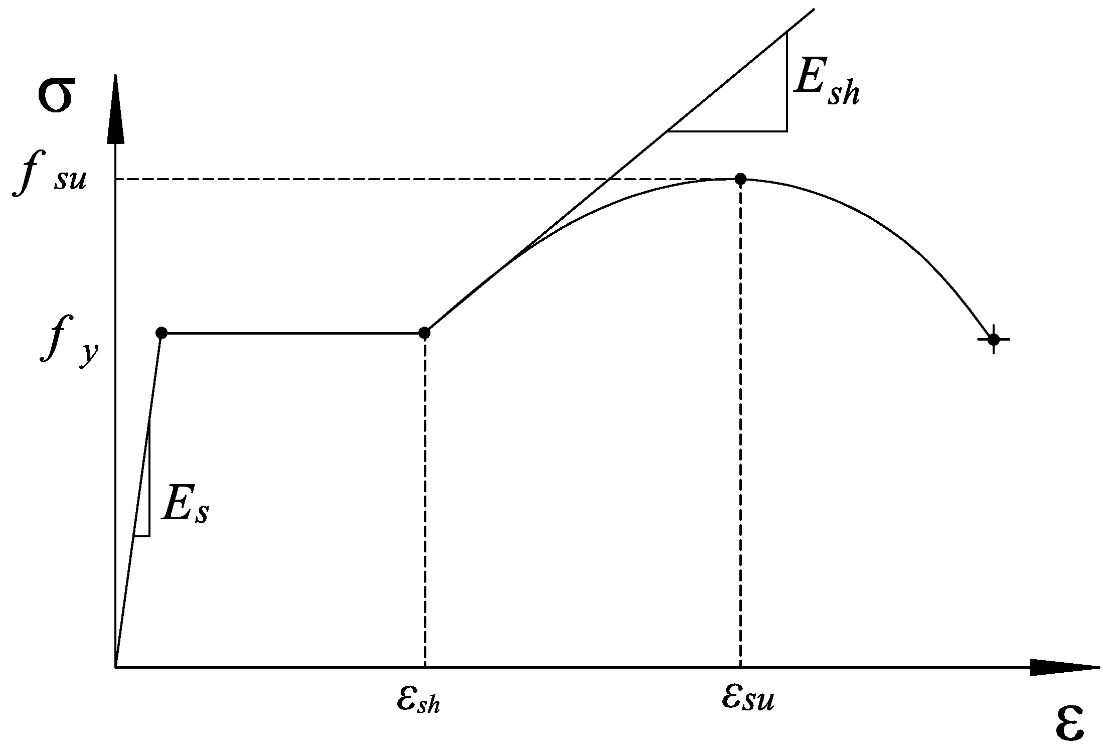
The Chang and Mander [26] model was adopted for the stress-strain relationship of steel bars. The key points of the stress-strain curve are described by defining the yield point (fy and εy), hardening point (fsh and εsh), and ultimate point (fsu and εsu), as shown in Figure 4. This material model is implemented as Reinforcing Steel in OpenSees and it can consider the Bauschinger effect. The mechanical behaviour of China-made steel bar (HRB400 Grade) under uniaxial tensile loading Figure 13 can be accurately simulated by OpenSees.
3.2.3. Steel-FRP Composite Bar
The stress-strain relation of compression is described as Equation (2). In the mechanical performance simulation of SFCBs using OpenSees, separate elements are established for the steel bar and FRP assuming a perfect FRP-steel bonding interface. The corresponding constitutive relationships are defined accordingly.
According to the composite principle, the composite bar can be defined as the core bar and FRP bar in the same position on the cross section. In the element model, the material of inner steel bar in composite bar use the “Reinforcing Steel” uniaxial material model, and mechanical properties use the value of experimental materials. The basalt FRP material type is Russian Gold CBF13-2400tex, and its physical and mechanical properties in OpenSees are shown in Table 3.
3.3. Verification of Numerical Modeling with Experimental Results
3.3.1. Comparison of Monotonic Pushover Test
For S12B43 beam, the predicted load firstly increases linearly with corresponding displacement before yield strength of 28.45 kN. After that, the curve has a turning point and keeps an approximate line at a lower slope until ultimate capacity is reached at 55.08 kN. At this stage, the load increases obviously and the displacement also increases to 56 mm. When the beam deformation and load continue to increase, concrete crushing occurs in the compression zone. Finally, the outer fiber begins to break and the components reach ultimate capacity. When most of the fiber breaks, the load drops sharply and the components fail. The simulated curves of monotonic loading beam can be divided into three stages. The predicted load firstly increases linearly with corresponding displacement before yielding of composite bar occurs. After that, the beam enters the stage of post-yield, both the load and displacement increase greatly at this stage, which ends with the fiber breaking and the member reaching the ultimate capacity.
The comparison of the monotonic load-lateral displacement curves between the experimental and simulation results are shown in Figure 14a. By comparison, it is found that the pushover analysis results agree well with the test results in terms of yield displacement, yield load, ultimate load and corresponding displacement. It is worth noting that the simulated yield displacement is slightly less than the test value. It shows that the numerical stiffness before yielding is larger than the test value. The simulation results are good for the ultimate capacity of concrete beam at the FRP fracture point and after fracture. The experimental and simulation curves show that the S12B43 beam has a stable post-yield stiffness. When the horizontal displacement is about 57 mm, the corresponding drift ratio is 4.75%, showing the specimen has good ductility. The moment that the load drops sharply indicates that the component is damaged. After the component is damaged, it still has a certain residual bearing capacity because the inner steel of the composite reinforcement is still at the yielding state.
3.3.2. Comparison of Cyclic Loading Test
The calculated and experimental hysteresis curves of the S12B97 beam are presented in Figure 14b. It can be seen that the numerical results of the beam correspond well with those obtained experimentally. Under the same displacement, the load value from the numerical simulation is slightly larger than the test result, which may be because the bond slip between SFCB and concrete is ignored in the numerical simulation. With the increase in lateral displacement, the concrete in the plastic hinge area broke off before the specimen failed. When the component is damaged, the phenomenon of fiber fracture and buckling of longitudinal bars occur. As the displacement increases, the corresponding load and stiffness decrease. The results of numerical simulation reflect this process effectively.
A comparison between simulation and experimental results for load and displacement at feature points is shown in Table 4. Generally speaking, the numerical simulation value is in good agreement with the experimental value. However, the error of Δy is bigger than the other results due to the reduction of the pre-yield stiffness in numerical simulation. In addition, the hysteretic curve of the experiment shows more pinch effect than the numerical simulation. Two factors might lead to these results, one is the slippage effect between the longitudinal reinforcement and concrete, the other is the shear deformation caused by concrete crack. Nevertheless, the simulation results give reasonable and accurate predictions for the experimental results. The numerical method for analyzing the seismic behavior of the concrete beam is verified. The proposed numerical method will be used to study the effects of different parameters on the seismic behavior of the beam reinforced with composite bars.
4. Parametric Study
After verifying the validity of the numerical modeling method in this paper, the numerical analysis can be carried out through the numerical simulation and changing parameters to consider their influence on the seismic performance of concrete beams. In the parametric study, the geometric dimensions and reinforcement layout are assumed to be the same as the beam discussed above. The influence of different parameters, including the outer fiber types of composite bars, concrete strength grades, shear span ratios of components and the relationship with the change of outer fibers area are discussed.
4.1. Effect of the Outer Fiber Types
One of the key points of the seismic design of beams reinforced with composite bars is how to choose the suitable FRP type (different FRPs have different elastic moduli, ultimate strengths, and elongation rates). In this paper, three types of FRP fiber, including carbon fiber, basalt fiber and glass fiber, are considered to study the mechanical properties of reinforced concrete beams.
When the diameter of inner steel is 12 mm, the number of outer fiber bundles in the composite bar is 30, 50 and 70 respectively. The concrete mechanical performance parameters are assumed to be the same as the beam discussed above. By changing the area of the outer FRP in longitudinal composite bar, the seismic performance of the beam is compared. The BFRP type is CBF13-4000tex, which is different from the properties of BFRP (2400tex) in contrast to the test above. The combination of CFRP and GFRP to steel is similar to BFRP. All the types and mechanical properties of the outer fiber in composite bars are cited from test data in [16], shown in Table 5. However, the mechanical properties of FRP in composite bars, such as the ultimate strength and the elongation at break are not the same as the mechanical properties of FRP filament. Generally speaking, the ultimate strength and elongation of composite bars are much less than that of the original fiber, which may be caused by the uneven force of the fiber when the composite bars are stretched.
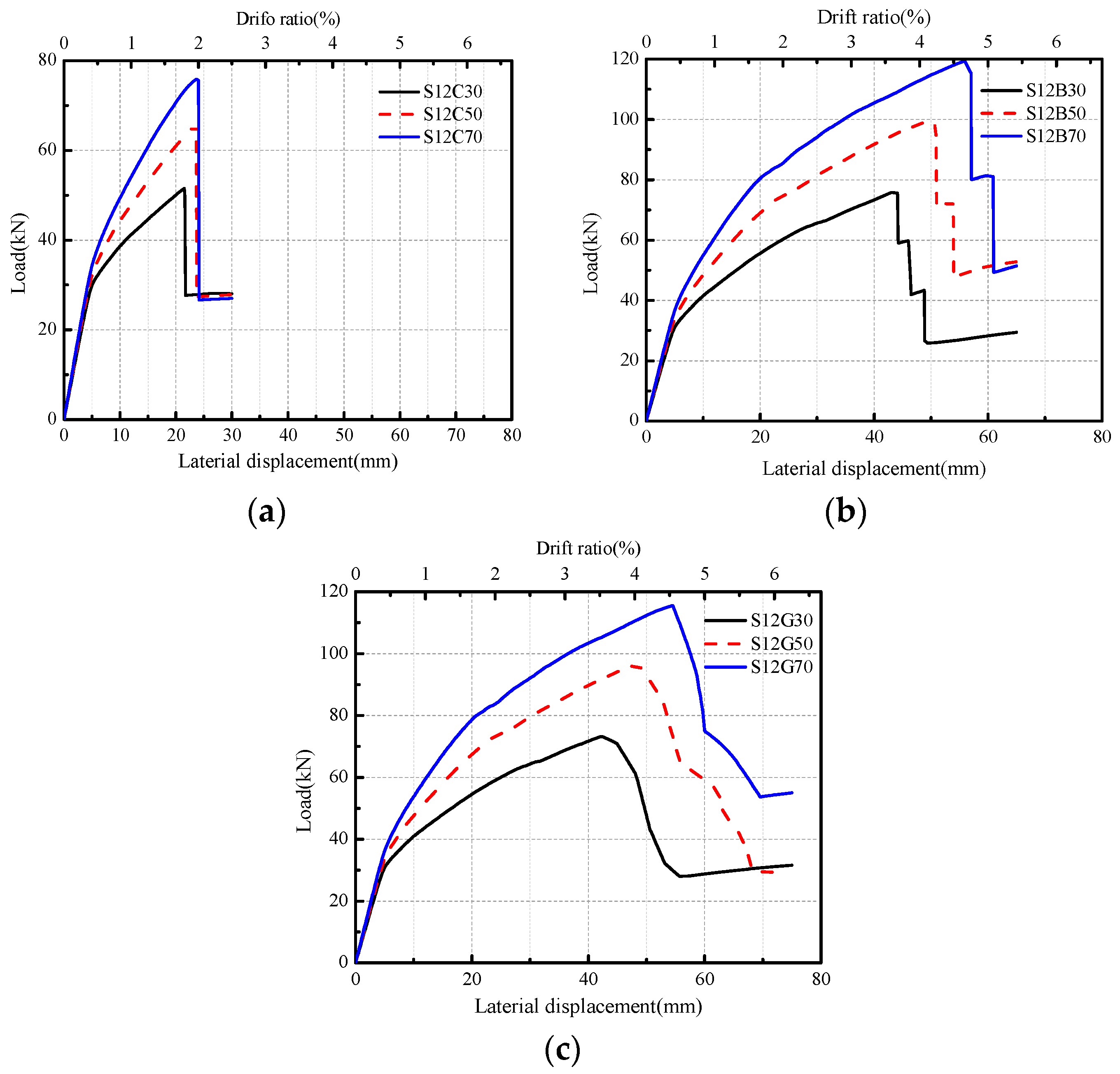
As shown in Figure 15, the yield displacement and initial stiffness are relatively close for each fiber type of SFCBs concrete beams. With the increase in fiber content, the post-yield stiffness of beam members increases gradually, and the FRP fracture point gradually moves backward. After FRP fracture, the beam load drops sharply. When the fiber content was increased to 70 bundles, the peak load of steel-BFRP reinforced concrete beam was the highest among the three FRP types beam models, about 120 kN. The beam reinforced with steel-GFRP composite bars was second, at 115.58 kN. The beam reinforced with steel-CFRP was last, about 75.80 kN. As the ultimate strain of CFRP is smaller than the other two fiber types, the damage caused by fiber fracture occurs firstly in steel-CFRP components. At this point, the concrete has not reached the ultimate compressive strain and the failure mode is brittle failure. The capacity of CFRP-related beam is smaller than the other two fiber types because the area per bundle is smaller. In addition, when the outer fiber of the composite bar breaks, taking the content of each type fiber bundle as 70 as an example, the horizontal drift ratio of the CFRP reinforced beam is only about 2.0%, the GFRP reinforced beam is 4.5%, while the BFRP composite beam is nearly 5.0%, with the best ductility. It was found that the post-yield stiffness and displacement ductility of components can be effectively improved by sound design of fiber content in composite bars. By comparing and analyzing the three kinds of FRP types, the concrete beams reinforced with steel-BFRP composite bars were found to have better ductility and maintain high ultimate capacity.
4.2. Effect of Concrete Strength
The comparison of beams reinforced with different types of fibers in Section 4.1 indicates that concrete beams reinforced with steel-BFRP composite bars have both good ductility and ultimate capacity. The following numerical simulation studies focus on the variable parameters based on beams reinforced with steel-BFRP composite bars.
In order to better compare the test beam specimens, the numerical simulation in Section 4.2 and Section 4.3 adopt the mechanical properties of the tested materials verified in Section 3.1 into the simulation model. In the model, BFRP original fiber is 2400tex, and its mechanical performance parameters are shown in Table 6 The load-horizontal displacement curve of the S12B50 beam is analyzed by changing the strength of concrete. The strength values are 30 MPa, 50 MPa and 70 MPa, respectively.
Figure 16 shows the influence of different concrete strength values on load-horizontal displacement curve of S12B50” beams. It can be seen that the curves coincide at the pre-yield stage, indicating that the change in concrete strength has a very limited impact on the strength and horizontal displacement of specimens at the initial elastic stage. However, the peak load and the post-yield stiffness increased gradually with the increase in concrete strength at the post-yield stage. As a result, when the concrete strength value is more than doubled, the seismic ultimate capacity of the beam increases by only 10% and the horizontal displacement at FRP fracture point decreased by only 2.7%, that is, the ductility did not change significantly.
Figure 17 shows the influence of concrete strength and fiber content on the seismic ultimate capacity and corresponding drift ratio of the component. The range of BFRP bundles in composite bars is from 50 to 90. As shown in Figure 17a, it is concluded that with the increase in concrete strength, the seismic ultimate capacity of concrete beam with different fiber content increases significantly. Figure 17b shows the effect of concrete strength on the ultimate drift ratio, with the increase in concrete strength, the drift ratio at the BFRP fracture point decreases gradually. Due to the elastic behavior of the FRP, all curves are linear to the fiber content. Under the same concrete strength, the ultimate drift ratio decreases more obviously with the increase of the fiber area in composite bars. However, the overall variation range is from 3.6 to 4.4, showing good ductility. It indicates that increasing the concrete strength of components blindly can improve the seismic ultimate capacity, but also reduce the ductility of components.
4.3. Effect of Shear Span Ratio
Since the shear span ratio and fiber content (area) are designable and have great effect on seismic performance of beam, the monotonic pushover analysis was carried out for concrete beams with different shear span ratios, from 3.5 to 5.5 to ensure that the beam is damaged mainly by bending failure. The range of BFRP bundles in composite bars is from 50 to 90.
Figure 18a shows the effect of the shear span ratio and fiber content on seismic ultimate capacity. For each fiber bundle reinforced beam, as the shear span ratio of beam increases, its seismic ultimate capacity decreases gradually. Figure 18b shows the effect of the shear span ratio and fiber content on the ultimate drift ratio. For each fiber bundle reinforced beam, the ultimate drift ratio increases significantly with the increase of the shear span ratio of beam. Due to elastic behavior of the BFRP, all curves are linear to the fiber content. When the shear span ratio is 3.5, the ultimate drift ratio of each beam is greater than 3%. When the shear span ratio is 5.5, the ultimate drift ratio of each beam is greater than 5%, and the increase is about 57%, showing good ductility.
5. Conclusions
In this paper, the seismic ultimate capacity of beams reinforced with SFCBs is studied by testing and numerical simulation. First, the method and main results of the experiment are briefly introduced, and based on the OpenSees software, a simplified constitutive model of composite bar material was applied to simulate the seismic behaviors of the concrete beams reinforced with SFCBs by fiber element modeling. The validity of the model was verified with the experimental results for the concrete beams reinforced with composite bars under monotonic loading and a low reversed cyclic load. Based on the numerical simulation method, a parametric study was then conducted to illustrate the effects of the FRP types in composite bars (i.e., basalt, carbon FRP and E-glass FRP), the concrete strength, FRP content of the SFCBs and shear span ratio. The results showed that (1) the fiber type of the composite bar has a great impact on the mechanical properties of the frame beam, with beam reinforced with BFRP composite bar having higher seismic ultimate capacity and better ductility; With the increase of the fiber bundle in the composite bar, the post-yield stiffness and ultimate capacity of the component increases and the ductility strengthens; (2) at pre-yield stage, concrete strength has little influence on seismic performance of concrete beam while after yielding, the seismic ultimate capacity and post-yielding stiffness of specimens are increased slowly with the increase in concrete strength, however, the ductility is reduced accordingly; (3) as the shear span ratio of beams increases from 3.5 to 5.5, the seismic ultimate capacity decreases gradually while the ultimate drift ratio increases by more than 50%. Through sensible setting of the fiber content and shear span ratio of the composite bar reinforced concrete beam, concrete beams reinforced with composite bars can have good ductility while maintaining high seismic ultimate capacity. Due to the limited number of the tested beams, more tests and analyses are needed to derive sound conclusions concerning the use of SFCB in concrete structural members in seismic prone regions.
Author Contributions
All authors have made a substantial contribution to this study. T.-L.X. designed the experiment and wrote the paper. H.-X.Q. provided the concept and design of the study. J.-L.L. performed the FEM simulation and analyzed the data.
Funding
This research was funded by the National Natural Science Foundation of China [No. 51708107] and the Natural Science Foundation of Colleges and Universities in Jiangsu Province, China [No. 17KJB560005].
Acknowledgments
The authors would like to acknowledge financial support from the National Natural Science Foundation of China (No. 51708107) and the Natural Science Foundation of Colleges and Universities in Jiangsu Province, China (No. 17KJB560005).
Conflicts of Interest
The authors declare no conflicts of interest.
References
- Hawileh, R.A.; Naser, M.Z. Thermal-stress analysis of RC beams reinforced with GFRP bars. Compos. Part B 2012, 43, 2135–2142. [Google Scholar] [CrossRef]
- Saafi, M. Effect of fire on FRP reinforced concrete members. Compos. Struct. 2002, 58, 11–20. [Google Scholar] [CrossRef]
- ACI 440.1R-15. Guide for the Design and Construction of Structural Concrete Reinforced with Fiber-Reinforced Polymer Bars; American Concrete Institute (ACI): Farmington Hills, MI, USA, 2015. [Google Scholar]
- Elgabbas, F.; Ahmed, E.; Benmokrane, B. Flexural behaviour of concrete beams reinforced with ribbed basalt-FRP bars under static loads. J. Compos. Constr. 2017, 21. [Google Scholar] [CrossRef]
- Zhu, H.T.; Cheng, S.Z.; Gao, D.Y.; Neaz, S.M.; Li, C. Flexural behaviour of partially fiber-reinforced high-strength concrete beams reinforced with FRP bars. Constr. Build. Mater. 2018, 161, 587–597. [Google Scholar] [CrossRef]
- Mousa, S.; Mohamed, H.M.; Benmokrane, B.; Ferrier, E. Flexural behaviour of full-scale circular concrete members reinforced with basalt FRP bars and spirals: Tests and theoretical studies. Compos. Struct. 2018, 203, 217–232. [Google Scholar] [CrossRef]
- Bank, L.C. Progressive Failure and Ductility of FRP Composites for Construction: Review. J. Compos. Constr. 2013, 17, 406–419. [Google Scholar]
- Ovitigala, T.; Ibrahim, M.A.; Issa, M.A. Serviceability and ultimate load behaviour of concrete beams reinforced with basaltfi ber-reinforced polymer bars. ACI Struct. J. 2016, 113, 757–768. [Google Scholar]
- Kara, I.F.; Ashour, A.F.; Köroglu, M.A. Flexural behaviour of hybrid FRP/steel reinforced concrete beams. Compos. Struct. 2015, 129, 111–121. [Google Scholar] [CrossRef]
- Wu, Z.; Yang, C.; Iwashita, K.; Mishima, H. Development of damage-controlled latter cast FRP–RC hybrid girders. Compos. Part B 2011, 42, 1770–1777. [Google Scholar] [CrossRef]
- Ibrahim, A.M.; Wu, Z.; Fahmy, M.F.; Kamal, D. Experimental study on cyclic response of concrete bridge columns reinforced by steel and basalt FRP reinforcements. J. Compos. Constr. 2015, 20. [Google Scholar] [CrossRef]
- Nanni, A.; Henneke, M.J.; Okamoto, T. Behaviour of concrete beams with hybrid reinforcement. Constr. Build. Mater. 1994, 8, 89–95. [Google Scholar] [CrossRef]
- Wu, G.; Wu, Z.S.; Luo, Y.B.; Sun, Z.Y.; Hu, X.Q. Mechanical properties of steel-FRP composite bar under uniaxial and cyclic tensile loads. J. Mater. Civ. Eng. 2010, 22, 1056–1066. [Google Scholar] [CrossRef]
- Xiao, T.L.; Qiu, H.X.; Sun, L.X. Experimental and theory study on the basic tensile and compression mechanical properties of steel-basalt fiber composite bars. J. Southeast Univ. 2014, 4, 805–810. [Google Scholar]
- Wu, G.; Sun, Z.; Wu, Z.; Luo, Y. Mechanical properties of steel-FRP composite bars (SFCBs) and performance of SFCB reinforced concrete structures. Adv. Struct. Eng. 2012, 15, 625–636. [Google Scholar] [CrossRef]
- Sun, Z.Y.; Yang, Y.; Qin, W.H.; Ren, S.T.; Wu, G. Experimental study on flexural behaviour of concrete beams reinforced by steel-FRP composite bars. J. Reinf. Plast. Compos. 2012, 31, 1737–1745. [Google Scholar] [CrossRef]
- Sun, Z.Y.; Wu, G.; Wu, Z.S.; Zhang, M. Seismic behaviour of concrete columns reinforced by steel-FRP composite bar. J. Compos. Constr. 2011, 15, 696–706. [Google Scholar] [CrossRef]
- Rahman, R.; Dirar, S.; Jemaa, Y.; Elshafie, M.Z.E.B. Experimental behaviour and design of exterior reinforced concrete beam-column joints Strengthened with Embedded Bars. J. Compos. Constr. 2018, 22, 15. [Google Scholar] [CrossRef]
- Sun, Z.Y.; Wu, G.; Wu, Z.-S.; Zhang, J. Nonlinear behaviour and simulation of concrete columns reinforced by steel-FRP composite bars. J. Bridge Eng. 2014, 19, 220–234. [Google Scholar] [CrossRef]
- Yao, L.Z.; Wu, G. Fiber-element modeling for seismic performance of square RC bridge columns retrofitted with NSM BFRP bars and/or BFRP sheet confinement. J. Compos. Constr. 2016, 20, 04016001. [Google Scholar] [CrossRef]
- Mazzoni, S.; McKenne, F.; Scott, M.H.; Fenves, G.L. Open System for Earthquake Engineering Simulation User Manual, Version 2.0; Pacific Earthquake Engineering Center, University of California: Berkeley, CA, USA, 2009; Available online: http://OpenSEES.berkeley.edu/OpenSEES/manuals/usermanual/index.html (accessed on 8 October 2018).
- Feng, D.C.; Li, J. Stochastic Nonlinear Behaviour of Reinforced Concrete Frames. II: Numerical Simulation. ASCE J. Struct. Eng. 2015, 142, 04015163. [Google Scholar] [CrossRef]
- Feng, D.C.; Wu, G.; Lu, Y. Numerical investigation on the progressive collapse behaviour of precast reinforced concrete frame subassemblages. J. Perform. Constr. Facil. 2018, 32, 1–14. [Google Scholar] [CrossRef]
- Lu, X.Z.; Xie, L.L.; Guan, H.; Huang, Y.L.; Lu, X. A shear wall element for nonlinear seismic analysis of super-tall buildings using OpenSEES. Finite Elem. Anal. Des. 2015, 98, 14–25. [Google Scholar] [CrossRef]
- Scott, B.D.; Park, R.; Priestley, M. Stress-strain behaviour of concrete confined by overlapping hoops at low and high strain rates. ACI J. 1982, 79, 13–27. [Google Scholar]
- Chang, G.A.; Mander, J.B. Seismic Energy-Based Fatigue Damage Analysis of Bridge Columns. II: Evaluation of Seismic Demand; Rep. NCEER-94-0013; National Center for Earthquake Engineering Research/State University of New York: Buffalo, NY, USA, 2004. [Google Scholar]
Figure 1.
Stress-strain relation of steel and fiber reinforced polymer (FRP) superposition.

Figure 2.
SFCB specimens.

Figure 3.
Tensile failure of SFCB.

Figure 4.
Load-displacement relationship of SFCB (test value).

Figure 5.
Lateral force-displacement history of specimen S12B97.

Figure 6.
Test setup.

Figure 7.
Dimension and reinforcement drawing of beam specimens (mm). (a) Schematic reinforcement; (b) Cross section of specimen S12B43; (c) Cross section of specimen S12B97.
Figure 7.
Dimension and reinforcement drawing of beam specimens (mm). (a) Schematic reinforcement; (b) Cross section of specimen S12B43; (c) Cross section of specimen S12B97.

Figure 8.
Crack patterns of specimen S12B43 (a) at yield load; (b) at peak load; (c) failure mode.

Figure 9.
Crack patterns of specimen S12B97 (a) at yield load; (b) at peak load; (c) failure mode.

Figure 10.
Load-displacement curves (test value). (a) S12B43 beam; (b) S12B97 beam.

Figure 11.
FEM and section division of beam. (a) Fiber element model; (b) Element division in cross section.
Figure 11.
FEM and section division of beam. (a) Fiber element model; (b) Element division in cross section.

Figure 12.
Concrete02 model in OpenSees.

Figure 13.
Mechanical properties of steel bar in OpenSees.

Figure 14.
Comparison between calculated and tested load-displacement curves of beam. (a) S12B43 beam; (b) S12B97 beam.
Figure 14.
Comparison between calculated and tested load-displacement curves of beam. (a) S12B43 beam; (b) S12B97 beam.

Figure 15.
Effect of fiber bundle increase on load-displacement pushover curve of concrete beams: (a) reinforced with steel-CFRP composite bars; (b) reinforced with steel-BFRP composite bars; (c) reinforced with steel-GFRP composite bars.
Figure 15.
Effect of fiber bundle increase on load-displacement pushover curve of concrete beams: (a) reinforced with steel-CFRP composite bars; (b) reinforced with steel-BFRP composite bars; (c) reinforced with steel-GFRP composite bars.

Figure 16.
Effect of concrete strength on the load-displacement pushover curve.

Figure 17.
Effect of increasing concrete strength and fiber content. (a) Effect of concrete strength on seismic ultimate capacity; (b) Effect of concrete strength on ultimate drift ratio.
Figure 17.
Effect of increasing concrete strength and fiber content. (a) Effect of concrete strength on seismic ultimate capacity; (b) Effect of concrete strength on ultimate drift ratio.

Figure 18.
Effect of shear span ratio and fiber content. (a) Effect of shear span ratio on seismic ultimate capacity; (b) Effect of shear span ratio on ultimate drift ratio.
Figure 18.
Effect of shear span ratio and fiber content. (a) Effect of shear span ratio on seismic ultimate capacity; (b) Effect of shear span ratio on ultimate drift ratio.


Table 1.
Mechanical properties of steel bar and composite bars.
| Bar Types | Diameter (mm) | Elastic Modulus (GPa) | Yield Strength (MPa) | Post-Yielding Elastic Modulus (GPa) | Ultimate Strength (MPa) | Ultimate Strain (10−3) | Post-Yield Stiffness Ratio | Strength Yield Ratio |
|---|---|---|---|---|---|---|---|---|
| S12 | 12 | 200 | 440 | - | 580 | - | - | - |
| S12B43 | 16.49 | 109.98 | 258.46 | 21.22 | 513.12 | 24.178 | 0.193 | 1.985 |
| S12B97 | 19.17 | 93.12 | 237.63 | 24.92 | 654.29 | 26.255 | 0.268 | 2.753 |
Table 2.
Constitutive control parameters of Concrete02 material.
| Concrete | f’c/MPa | fcu/MPa | ft/MPa | |||
|---|---|---|---|---|---|---|
| unconfined | 26.20 | 0.0020 | 5.24 | 0.0044 | 0.1 | 2.01 |
| confined | 34.06 | 0.0026 | 6.81 | 0.0277 | 0.1 | 2.01 |
Table 3.
Mechanical and physical properties of BFRP fibers in OpenSees.
| Fiber Types | Original Fiber Strength (MPa) | Fiber Ultimate Strength in SFCBs (MPa) | Original Fiber Elongation (%) | Elongation in SFCBs (%) | Area (mm2/bundle) |
|---|---|---|---|---|---|
| BFRP(2400tex) | 2250 | 1540 | 2.5 | 2.2 | 0.833 |
Table 4.
Comparison between simulation and experimental results for load and displacement at feature points.
Table 4.
Comparison between simulation and experimental results for load and displacement at feature points.
| Specimens | Pcr/kN | Δcr/mm | Py/kN | Δy/mm | Pp/kN | Δp/mm | Pu/kN | Δu/mm | |
|---|---|---|---|---|---|---|---|---|---|
| S12B43 | test | 7.75 | 1.41 | 31.51 | 11.27 | 53.30 | 57.15 | 30.00 | 58.01 |
| simulation | 7.78 | 1.30 | 28.45 | 5.20 | 55.08 | 56.00 | 28.42 | 59.50 | |
| Error (%) | 0.39 | 7.80 | 9.71 | 53.86 | 3.34 | 2.01 | 5.27 | 2.57 | |
| S12B97 | test | 10.25 | 1.67 | 30.28 | 11.24 | 76.63 | 60.14 | 57.84 | 71.88 |
| simulation | 9.78 | 1.50 | 32.04 | 5.50 | 84.48 | 63.00 | 57.61 | 71.50 | |
| Error (%) | 4.59 | 10.18 | 5.81 | 51.07 | 10.24 | 4.76 | 0.40 | 0.53 | |
Pcr, Py, Pp and Pu represent cracking load, yield load, peak load and ultimate load respectively; Δcr, Δy, Δp and Δu represent corresponding displacements. For specimen S12B97, take the average values of positive and negative skeleton curve as the characteristic values.
Table 5.
Tested values of mechanical and physical properties of different fibers in SFCBs.
| Fiber Types | Original Fiber Strength (MPa) | Fiber Ultimate Strength in SFCBs (MPa) | Original Fiber Elongation (%) | Elasticity Modulus (GPa) | Elongation in SFCBs (%) | Density (g/cm3) | Area (mm2/Bundle) |
|---|---|---|---|---|---|---|---|
| CFRP (T700) | 3680 | 2760 | 1.6 | 230 | 1.2 | 1.80 | 0.448 |
| BFRP (CBF13-4000tex) | 2250 | 2070 | 2.5 | 90 | 2.3 | 2.63 | 1.520 |
| GFRP (E-Glass) | 2000 | 1606 | 4.4 | 73 | 2.2 | 2.70 | 1.780 |
Table 6.
Mechanical and physical properties of BFRP fibers in OpenSees.
| Fiber Types | Original Fiber Strength (MPa) | Fiber Ultimate Strength in SFCBs (MPa) | Original Fiber Elongation (%) | Elongation in SFCBs (%) | Area (mm2/bundle) |
|---|---|---|---|---|---|
| BFRP (2400tex) | 2250 | 1540 | 2.5 | 2.2 | 0.833 |
© 2018 by the authors. Licensee MDPI, Basel, Switzerland. This article is an open access article distributed under the terms and conditions of the Creative Commons Attribution (CC BY) license (http://creativecommons.org/licenses/by/4.0/).
Share and Cite
MDPI and ACS Style
Xiao, T.-L.; Qiu, H.-X.; Li, J.-L. Seismic Behaviors of Concrete Beams Reinforced with Steel-FRP Composite Bars under Quasi-Static Loading. Appl. Sci. 2018, 8, 1913. https://doi.org/10.3390/app8101913
AMA Style
Xiao T-L, Qiu H-X, Li J-L. Seismic Behaviors of Concrete Beams Reinforced with Steel-FRP Composite Bars under Quasi-Static Loading. Applied Sciences. 2018; 8(10):1913. https://doi.org/10.3390/app8101913
Chicago/Turabian StyleXiao, Tong-Liang, Hong-Xing Qiu, and Jia-Le Li. 2018. "Seismic Behaviors of Concrete Beams Reinforced with Steel-FRP Composite Bars under Quasi-Static Loading" Applied Sciences 8, no. 10: 1913. https://doi.org/10.3390/app8101913
Note that from the first issue of 2016, this journal uses article numbers instead of page numbers. See further details here.