Abstract
Due to the limitations on the capabilities of current robots regarding task learning and performance, imitation is an efficient social learning approach that endows a robot with the ability to transmit and reproduce human postures, actions, behaviors, etc., as a human does. Stable whole-body imitation and task-oriented teleoperation via imitation are challenging issues. In this paper, a novel comprehensive and unrestricted real-time whole-body imitation system for humanoid robots is designed and developed. To map human motions to a robot, an analytical method called geometrical analysis based on link vectors and virtual joints (GA-LVVJ) is proposed. In addition, a real-time locomotion method is employed to realize a natural mode of operation. To achieve safe mode switching, a filter strategy is proposed. Then, two quantitative vector-set-based methods of similarity evaluation focusing on the whole body and local links, called the Whole-Body-Focused (WBF) method and the Local-Link-Focused (LLF) method, respectively, are proposed and compared. Two experiments conducted to verify the effectiveness of the proposed methods and system are reported. Specifically, the first experiment validates the good stability and similarity features of our system, and the second experiment verifies the effectiveness with which complicated tasks can be executed. At last, an imitation learning mechanism in which the joint angles of demonstrators are mapped by GA-LVVJ is presented and developed to extend the proposed system.
1. Introduction
Robots can be used in place of humans to perform remote tasks such as remote meetings/interactions [1,2], telesurgery [3,4,5,6], rehabilitation [7], and search and rescue [8]. However, the ability to control a humanoid robot with a high degree of freedom using a traditional controller or through preprogramming based on human experience strongly depends on the operation skills of the users, the programming skills of the developers, and the availability of extensive experience. As an alternative, imitation is an efficient social learning approach that endows a robot with the ability to transmit and reproduce human postures, actions, behaviors, etc., as a human does. The questions of how to achieve accurate, stable, and complete whole-body imitation and how to evaluate the imitation similarity are two basic issues facing this approach.
Generally, robotic imitation consists of three phases, i.e., observation, representation and reproduction [9]. The observation process usually relies on either marker-based or markerless visual capture systems or dynamic capture systems to acquire human motions. In a marker-based visual capture system, markers must be placed on the demonstrators to indicate the positions of their body parts [10,11,12,13,14], whereas a markerless visual capture system can directly extract 2D or 3D information from video frames [15,16,17,18,19,20]. The imitation system presented in [21] obtained motion data using the Xsens MVN dynamic capture system (Enschede, The Netherlands), which offers high precision but is inconvenient and expensive. Our real-time imitation system uses the Microsoft Kinect II (Redmond, Washington, USA), which costs much less and is more user-friendly, to capture 3D skeleton points and track the faces of the demonstrators.
In the representation process, the observed actions are mapped to the internal representation of the robot. The traditional approaches for posture mapping are numerical methods of inverse kinematic (IK) computations [10,16,17,21,22,23,24]. The numerical IK method is effective for manipulating the end effectors of robots in the work space, but it is a relatively indirect and imprecise means of producing motions in joint space, and it incurs a rather high computational cost. Because the joint angles determine the posture of the robot, a precise mapping in joint space will be beneficial for the imitation similarity. To enable the generation of more human-like actions with less computation, new methods will be necessary.
To this end, several analytical methods have been exploited [13,14,19,20,25,26,27,28,29]. In addition to the positions of the end effectors, other information such as the positions of the joints is obtained in these methods. An inherent advantage of analytical methods with constraints is that the solutions generated using such analytical methods are more direct, accurate and efficient. Consequently, it is easier to obtain accurate joint angles for mapping that correspond to an observed posture and thus achieve a high imitation similarity. However, most existing geometrical analytical mapping methods used in imitation learning cannot obtain the specific orientations of each “body link” in a demonstrated human posture [13,20,25,26,27,28]. In addition, the details of the robot’s joint structures, such as mother and child joint features, are not fully considered when calculating the joint angles for mapping, and the imitation similarity of the generated postures suffers as a result. Some researchers have directly used the rotation matrices provided by the Kinect software development kit (SDK) or the Open NI library, which have been proven to be unstable and imprecise [19,25]. In this paper, a novel method for motion mapping, GA-LVVJ, is proposed to solve the above problems. In the existing robot imitation work, to the best of our knowledge, no similar analytical motion mapping method is systematically documented in detail. Our proposed method GA-LVVJ provides a framework of motion mapping with the 3D information of skeleton points, and deals with the problems on how to construct virtual joints of the human skeleton model in accordance with the robot joints, how to establish link frames attached to the link vectors and how to extract joint angles for mapping using the geometrical method. This method proves the high similarity of the single-support and double-support imitation motions with low computational cost.
Upper-body imitation has been studied for many years [10,12,14,15,19,22,30,31,32,33,34,35,36]. Compared with upper-body imitation, whole-body imitation is more comprehensive and complicated. Whole-body imitation usually involves multi-mode lower-body imitation and balance control [13,16,17,18,20,21,23,24,25,26,37]. Kondo et al. proposed a method of joint angle generation using a particle filter, which was based on a designed similarity function [18]. However, the particle filter could not ensure standing stability, and, consequently, a robot controlled in this way was limited to a doubly supported posture (standing on two feet). Hwang et al. studied upper-body and lower-body imitation separately to ensure stability [16]. The postures were estimated by means of neural-network-based inverse kinematics and five feature points extracted from a stereo-vision system, but only 11 preset stable motions were available for the lower body. Lin et al. modified key postures via a Q-learning process to maintain a robot’s balance during imitation [38]. It was necessary to train the balance control process in advance, and only limited numbers of joint angles could be modified independently using several fixed preset values. In [25], the HipRoll joint of the swing leg was locked during the single-support phase, and the unstable imitation of the lower-body motion sometimes led to falling down. Lei et al. presented a method of maintaining whole-body balance when imitating single poses or a pose sequence [26]. However, the landing of the foot when transitioning from the single-support to the double-support phase was not considered. Moreover, walking and hand detection, which are essential for task execution, also were not taken into account. In [23], Ou et al. proposed a real-time imitation system based on the Kinect. The system derived robot joint angles by applying the Levenberg–Marquardt algorithm to the IK optimization problem and achieved both double and single support by means of an “Ankle Strategy” [37] and a “Hip Strategy”. Liu et al. also adjusted the ankle joints to maintain balance [13]. Still, walking and hand detection were not considered.
Walking must be considered for true whole-body imitation. Koenemann et al. used the Xsens MVN motion capture system to achieve stable whole-body imitation via the numerical inverse kinematics method [21]. The end effector was retargeted if the posture was not stable. The system enabled the robot to imitate a human gait at a low velocity, but the demonstrator was required to lift his or her leg slowly and high, which is inconvenient and inconsistent with spontaneous human walking motions. Poubel et al. focused on the problem of shifting the support leg and lifting/lowering the foot during motion imitation via task specification [17,24]. These authors avoided using motion primitives, and the robot acted in a freer and more human-like manner when shifting the support leg, stepping and walking. However, the locomotion functionality remained limited because of the low stepping velocity. Using a different approach from these methods, some researchers have controlled the locomotion of a robot by using preprogrammed walking primitives to make it easier for the demonstrator to operate the robot. The system developed in [39] used a depth camera to record the positions of the human demonstrator and calculate the displacements, but it required a Wiimote as ancillary equipment to tell the system when to record the initial and final positions. In [40], a humanoid robot was made to imitate human upper-limb motions and was issued walking, hand closing and opening, and mode switch instructions via speech signals to complete a pen shopping task. Almetwally et al. used additional postures to switch on/off the locomotion function and successfully directed a robot to pick up a ball using upper-limb imitation [29,41]. The system had only one static reference position for locomotion, and the additional postures were not spontaneous human motions; consequently, the operation was relatively time-consuming and inconvenient. In [25], an imitation system was used to issue walking instructions by means of upper-limb postures. The volunteers participating in this research verified the difficulty of this method.
Some imitation systems involving dynamic balance have been proposed and developed in recent years. The work presented in [42] focused on controlling the legs of the humanoid robot by a master-slave approach to realize dynamic biped walking. In [43], the authors improved their system by proposing a set of safety limitations to meet the dynamics of Linear Inverse Pendulum at any time. Furthermore, they calculated additional reference ZMP informations without the foot force sensor devices they had used before, which relieved operation stress of the operator. In [44,45], the authors proposed, designed and developed a whole-body human-in-loop teleoperation control system with balance feedback, which enabled the operator to control the robot to perform powerful manipulation tasks. Their works are impressive and enlightening to our work. On the other hand, while their works focused on humanoid robot’s capability and stability of dynamic biped locomotion and performing tasks, the whole-body imitation similarity might be limited. In the work presented in [42,43], the authors only used the information of the human’s end effector and center of mass to generate reference joint angles, and the foot height was also restricted. In [44,45], only upper limbs and hips were considered in the motion mapping, and the motions of the lower limbs subjected to the torso orientation of the operator. The single-support motions were also not mentioned in this work. Our focus is quite different. We mainly focus on generating comprehensive stable whole-body imitation motions of the humanoid robot with high similarity. Other than the positions of the end effectors, the positions of the joints are fully considered in our motion mapping methods, to endow the robot with the ability of generating more similar human behaviors. In terms of user friendliness, our system only employs a RGB-D camera (the camera which provides color information and estimated depth information) to obtain the human body information, and does not need any wearable devices used in the above work.
The evaluation of the motion similarity between a human demonstrator and a humanoid robot is another critical issue for both the optimization of multiple solutions and the assessment of the effectiveness of an imitation system. For solution optimization, in [23], the imitation similarity was measured by calculating the distance between the normalized vectors representing the human and the robot, and the corresponding error function was applied in the IK optimization problem. Alissandrakis et al. presented state, action and effect metrics for different correspondence mappings associated with various imitators and imitation tasks [46]. For assessing the effectiveness of an imitation system, Zuher et al. used an evaluation metric called the Mean Opinion Score to quantify the imitation quality [25]. However, this approach was subjective and not sufficiently accurate. In [16,17,21,24], the researchers evaluated the imitation similarity by determining the position errors of the end effectors between the scaled human model and the robot; however, this approach could not completely reflect the similarity of the postures because the end effectors represent only a few points on the entire body. In [26], the author presented a quantitative metric of the similarity between a human pose and a robot pose based on the latent spaces of the human and the robot; the poses were represented by joint angles, which also provide an indirect representation of posture. With regard to metrics that are not specifically aimed at imitation systems, Zhang et al. evaluated the human-like behavior of the Nadine robot by calculating the Pearson product-moment correlation coefficients of key points captured by a depth camera between the humanoid robot and the human demonstrator [47]. Harada et al. constructed a quantitative evaluation method for pose and motion similarity in accordance with human perception [48]. The weights of the body regions were optimized to ensure the highest correlation coefficients between the quantitative similarities and average human intuition. The quantitative evaluation was based on the positions and angles of the body regions, which do not directly represent the posture and do not consider the different effects of different joints on the posture. To improve the evaluation of imitation similarity, two quantitative vector-based similarity evaluation criteria are proposed in this paper.
Overall, the constraints of the previous research on robotic imitation are as follows:
- Most imitation systems that can achieve stable whole-body motions are based on numerical IK methods for posture mapping. However, joint angles generated using numerical methods are not as accurate as those obtained using analytical methods and incur higher computation costs.
- Most analytical methods of joint angle mapping used in imitation systems are simple and rough, and they cannot indicate the orientations of human body links and lack sufficient consideration of the robot’s joint structures. This will affect the accuracy of the joint angles for mapping and limit the imitation similarity.
- Many approaches cannot achieve stable doubly supported and singly supported imitation.
- Most researchers have not considered the imitation of head motions, hand motions or locomotion, which are essential for task execution using an imitation system. Some systems partially accomplish these functions but require additional postures or audio instructions or require ancillary handheld or wearable devices, which are inconvenient.
- Most similarity criteria are based on the positions of key points, i.e., the positions of end effectors or skeleton points, or are based on joint angles and consequently cannot directly reflect the posture similarity.
To solve the problems identified above and improve the performance of real-time imitation systems, a novel stable, complete and unrestricted whole-body imitation system is proposed and developed in this paper. In addition, vector-set-based and multi-focused methods of imitation evaluation are proposed and employed to evaluate our real-time imitation system. The main contributions of this paper can be summarized as follows:
- A novel comprehensive and unrestricted whole-body imitation system is proposed and developed. In addition, an imitation learning algorithm is presented and developed based on it. To the best of our knowledge, it is the most complete and free whole-body imitation system developed to date, enabling the imitation of head motions, arm motions, lower-limb motions, hand motions and locomotion and not requiring any ancillary handheld or wearable devices or any additional audio or gesture-based instructions. The system includes a double-support mode, a single-support mode and a walking mode. The balance is controlled in each mode, and the stability of the system enables the robot to execute some complicated tasks in real time.
- A novel analytical method called GA-LVVJ is proposed to map the human motions to a robot based on the observed human data. Link vectors are constructed according to the captured skeleton points, and the virtual joints are set according to the link vectors and the robot joints. Then, the frame of each human skeleton model link is built to indicate its orientation and posture. A structural analysis of child and mother joints is employed for the calculation of the joint angles. This method proves the high similarity of the single-support and double-support imitation motions.
- A real-time locomotion method is proposed for the walking mode. Both the rotations and displacements of the human body are calculated in real time. No ancillary equipment is required to issue instructions for recording the position, and no fixed point is needed to serve as a reference position.
- A filter strategy is proposed and employed to ensure that the robot transitions into the correct motion mode and that its motions are stabilized before the mode changes.
- Two quantitative vector-based similarity evaluation methods are proposed, namely, the WBF method and the LLF method, which focus on the whole-body posture and the local-link posture, respectively. They can provide novel metrics of imitation similarity that consider both whole-body and local-link features.
2. System Framework
The framework of the proposed whole-body imitation system is shown in Figure 1. The whole framework includes four stages, i.e., the observation stage, the motion mapping stage, the mode switch stage and the reproduction stage. In the observation stage, human motions are captured by the RGB-D camera and 3D skeleton points of the human body are extracted. Then, in the motion mapping stage, the human skeleton model is constructed through GA-LVVJ, and the human motions are mapped to the robot body by using the proposed joint mapping (through GA-LVVJ), head motion mapping, hand motion mapping and locomotion mapping methods. It is worth pointing out that, since the information obtained from the skeleton data is limited and insufficient, auxiliary approaches (in addition to the GA-LVVJ method) for the head motions and hand motions of a humanoid robot are employed. In the mode switch stage, the robot will switch to the double-support mode, the single-support mode or the walking mode according to the state of the human skeleton model. In the reproduction stage, if the robot is in the double-support or the single-support mode, the mapped joint angles will be adjusted lightly through the balance control and then produce stable whole-body imitation motions. If the robot switches to the locomotion mode, the mapped locomotion data will be applied to replicate human rotations and displacements.
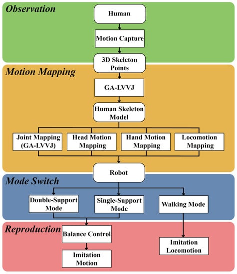
Figure 1.
The framework of the proposed whole-body imitation system.
3. Motion Mapping
To realize whole-body imitation, the motions of a human demonstrator need to be mapped to a robot. Specifically, we consider joint mapping (through GA-LVVJ), head motion mapping, hand motion mapping and locomotion mapping in the proposed system. In this section, the methods of motion mapping from the human to the robot are described in detail.
3.1. Motion Loop and Locomotion Loop
Human motion data are consecutively acquired by an RGB-D camera. In our system, a motion loop includes the processing of the motion data from one frame and a series of execution orders in accordance with the corresponding motion data. A locomotion loop includes multiple consecutive motion loops; the number of motion loops included depends on the duration of one motion loop, which is uncertain for each one. At the start of each locomotion loop, the position of the demonstrator is compared with his or her position from the last locomotion loop. If the conditions for locomotion are satisfied, the robot will transition into the walking mode and walk to cover the corresponding displacement and rotation angle.
3.2. Construction of Human Skeleton Model and Joint Mapping: GA-LVVJ
The GA-LVVJ method is proposed for mapping human postures to a robot by building the human skeleton model and extracting joint angles. Without loss of generality, GA-LVVJ includes the following steps:
- Construction of human skeleton link vectors in accordance with the 3D skeleton points;
- Construction of human virtual joints in accordance with the human skeleton link vectors and robot joints;
- Establishment of local link frames for the human skeleton model with reference to the virtual joints;
- Calculation of the joint angles of the human skeleton model using the local link frames and link vectors;
- Application of the joint angles of the human skeleton model to the robot.
In our system, a Kinect II RGB-D camera is used to capture human motions. To extract 3D skeleton points of the human body, which include points corresponding to the end effectors and joints from the body frames acquired by Kinect, we used the API provided by the Kinect for Windows SDK 2.0 [49], which is a basic library for the Kinect sensor. The names and serial numbers of these skeleton points used in this paper are shown in Figure 2. Thereafter, a complete skeleton model of the human body, referred as the human skeleton model in this paper, will be built based on these points, the process of which will be described detailedly in this section. The maximum errors in displacement of the upper body skeleton points obtained from Kinect I, measured in [50], is lower than 38 mm. In [51], Kinect II was proved to have better performances than Kinect I. Generally, a wearable motion capture system is more accurate than a visual motion capture system, but the visual motion capture systems have their merits and are widely used. Furthermore, the Kinect II sensor performs well in our hands-on experiments, so the human skeleton model constructed from the skeleton points acquired by Kinect II is considered to well represent the human demonstrator.
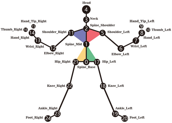
Figure 2.
Names and numbers of skeleton points captured by the Kinect II.
We can obtain the link vectors formed by pairs of skeleton points. The subscript i denotes the number of the skeleton point at which the vector begins, and j denotes the number of the skeleton point to which the vector points. It is worth pointing out that the proposed GA-LVVJ method is a general mapping method which can be applied to most types of humanoid robots. Without loss of generality, the NAO robot is used as an example here. Figure 3 depicts the joints and corresponding joint angles of NAO.
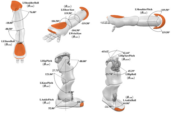
Figure 3.
Upper- and lower-limb joints and joint angles of the NAO robot.
In this paper, if two joints or two links are on the same limb chain, the one closer to the torso is defined as the mother joint or mother link, whereas the other one is defined as the child joint or child link. A link frame is attached to each link and indicates the link’s position and orientation, the link frames of NAO are shown in Figure 4. The origin of a link frame is located at the intersection between the link itself and its child link or at the center of mass of a link.
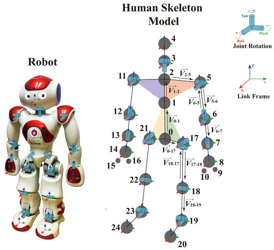
Figure 4.
Joint structures and link frames of the robot and the human skeleton model.
In order to map human postures to the robot through a geometrical analysis of the joint angles, the joint structures and each link frame of the human skeleton model should be established. The link frames of the human skeleton model serve as the references for the calculation of the joint angles for mapping. In order to construct them, virtual joints of the human skeleton model similar to those of the robot are established, as shown in Figure 4, regardless of what the real joint structures of the human body are. The axis of each joint is set collinear with or vertical to the vector of the mother link in the initial posture. Then, the link frames should be set in accordance with the axes of the joints at each intersection between a link and its child link. The origin of a link frame is located at the intersection between the link itself and its child link, as depicted in Figure 4. The postures of the robot and the human skeleton model that are shown in Figure 4 are defined as the initial postures in this paper. The LShoulderPitch and RShoulderPitch angles are equal to , whereas all other joint angles in the initial posture are zero. These joint angles are defined as the initial joint angles.
To improve the accuracy of the joint mapping, when extracting the angle of the mother joint between two link vectors, the child link vector should be first projected on the plane vertical to the coordinate axis which represents the rotation axis of the mother joint, then this joint angle can be calculated through the angle between the projected vector and another vector on this plane. When extracting the angle of the child joint between two link vectors, the joint angle can be obtained through the angle between the child link vector and the same plane mentioned above. If there is only one joint between two link vectors, it can be regarded as a mother joint.
It is worth noting that since the human torso is not rigid, skeleton points 0, 1, 2, 5, 11, 17 and 21 in the human skeleton model may not all be in the same plane. As shown in Figure 4, to obtain more accurate joint angles, the torso of the human skeleton model is divided into four parts, i.e., the left upper torso, the right upper torso, the left lower torso and the right lower torso. Compared with a single-frame method (such as a method based on a single torso frame [28] or a fixed world frame [13,27]), the proposed method of torso segmentation yields more precise joint angles for the human skeleton model and improves the imitation similarity for local postures.
Next, the process of obtaining several key joint angles for the left side of the body will be presented as an example of GA-LVVJ.
(1) Joints of Shoulder_Left: The angles of shoulder joints should be calculated with reference to upper torso links. The axis of LShoulderPitch is collinear with the vector . Because LShoulderRoll is the child joint of LShoulderPitch, its axis changes with the rotation of LShoulderPitch and is collinear with the the normal vector to Plane 2-5-6, , which is calculated as
When LShoulderPitch is at its initial angle, the axis of LShoulderRoll is collinear with the normal vector to the left upper torso plane, , i.e.,
Then, is translated to the origin of the link frame of the left upper torso, point 5, and the x-axis of the frame is set collinear with , as depicted in Figure 5. Because the axis of LShoulderPitch is vertical to the torso link in NAO but may not be in the human skeleton model, , which represents the upper torso link, rather than , which is aligned with the axis of LShoulderPitch in the human skeleton model, is translated to point 5 and set collinear with the x-axis of the link frame. is collinear with the z-axis. Then, a reference vector is introduced and set collinear with the y-axis to complete a right-handed frame; this vector is obtained as follows:
where the subscript LUT is an abbreviation for “left upper torso”.
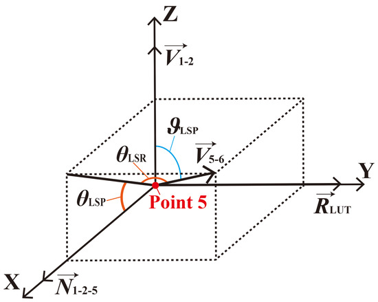
Figure 5.
The link frame of the left upper torso of the human skeleton model and the shoulder joint angles for mapping.
As previously discussed, LShoulderPitch is the mother joint of LShoulderRoll. To achieve a more similar local posture of the left upper arm relative to the left upper torso as the reference, which means that the orientation of the left upper arm link in the frame of the left upper torso link of the robot should be consistent with that in the human skeleton model, the geometrical forms of the angles of these two adjacent joints (i.e., LShoulderPitch and LShoulderRoll) should be distinguished. As illustrated in Figure 5, the angle of LShoulderPitch, , should be calculated in accordance with the angle between and the projection of onto the x–z plane, which is also the angle between the x–y plane and the plane formed by and , i.e.,
To obtain , an intermediate variable is defined as follows:
Then, is obtained as
The angle of LShoulderRoll, , should be calculated from the angle between and the x-z plane, i.e.,
(2) Joints of Elbow_Left: The axis of LElbowYaw is collinear with the vector . Because LElbowRoll is the child joint of LElbowYaw, its axis changes with the rotation of LElbowYaw and is collinear with the normal vector to Plane 5-6-7, , which is calculated as
When LElbowYaw is at its initial angle, the axis of LElbowRoll is collinear with . As depicted in Figure 6, and are translated to the origin of the link frame of the left upper arm, point 6, and the x- and z-axes of the frame are set collinear with and , respectively. Then, a reference vector is set collinear with the y-axis to complete a right-handed frame; this vector is obtained as follows:
where the subscript LUA is an abbreviation for “left upper arm”.
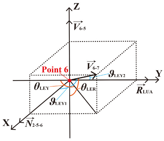
Figure 6.
The link frame of the left upper arm of the human skeleton model and the elbow joint angles for mapping.
The angles of elbow joints should be calculated in the frames of upper arm links. As shown in Figure 6, the angle of LElbowYaw, , should be calculated from the angle between the projection of onto the x–y plane and the reverse of , which is also the angle between the y–z plane and the plane formed by and , i.e.,
To obtain , intermediate variables and are needed, i.e.,
Then, is
The angle of LElbowRoll, , should be calculated in accordance with the angle between and the x–y plane plus , which can also be calculated as
(3) Joints of Hip_Left: As depicted in Figure 4, LHipRoll is the mother joint of LHipPitch; its axis is collinear with the normal vector of the left lower torso, , which is calculated as
The axis of LHipPitch changes with the rotation of LHipRoll and is collinear with the normal vector to the plane formed by and . When LHipRoll is at its initial angle, the axis of LHipPitch is collinear with .
Then, is translated to the origin of the link frame of the left lower torso, point 17, and the x-axis of the frame is set collinear with , as depicted in Figure 7. Because the axis of LHipPitch in the initial posture is vertical to the torso link in NAO but may not be in the human skeleton model, , which represents the lower torso, rather than , which is aligned with the axis of LHipPitch in the human skeleton model, is translated to point 17 and set collinear with the x-axis of the link frame. is collinear with the z-axis. Then, a reference vector is set collinear with the y-axis to complete a right-handed frame; this vector is obtained as follows:
where the subscript LLT is an abbreviation for “left lower torso”.
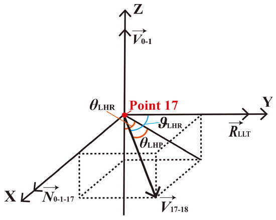
Figure 7.
The link frame of the left lower torso of the human skeleton model and the hip joint angles for mapping.
The angles of hip joints are calculated in the frames of lower torso links. As illustrated in Figure 7, the LHipRoll angle, , should be calculated in accordance with the angle between the reverse of and the projection of onto the y–z plane, which is also the angle between the x-z plane and the plane formed by and , i.e.,
To obtain , is introduced:
Then, is obtained as
The angle of LHipPitch, , should be computed from the angle between and the y–z plane, i.e.,
(4) Joint of Knee_Left: The axis of LKneePitch is collinear with the normal vector to Plane 17–18–19, , which is calculated as
Then, is translated to the origin of the frame of the left thigh, point 18, and set collinear with the y-axis of the frame, as illustrated in Figure 8. is collinear with the z-axis of the frame. A reference vector that is collinear with the x-axis is introduced to complete a right-handed frame; this vector is obtained as follows:
where the subscript LTh is an abbreviation for “left thigh”.
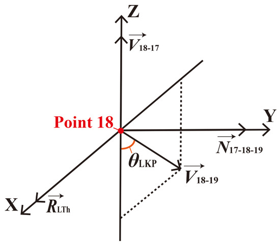
Figure 8.
The link frame of the left thigh of the human skeleton model and the knee joint angle for mapping.
Knee joint angles are calculated in the frames of thigh links. The angle of LKneePitch, , should be computed in accordance with the angle between the projection of onto the x-z plane and the reverse of . Because the left knee joint has only one degree of freedom (DOF), is on the x-z plane of the frame of the left thigh; consequently, can be obtained as follows:
The joint angles obtained above are considered to be the joint angles of the human skeleton model and will be set as the target joint angles of the robot. If the value of any angle is beyond the limit of the corresponding robot joint, the angle will be assigned a marginal value when it is applied to the robot joint.
3.3. Head Motion Mapping
To enable the robot agent to act more like a human and allow the human demonstrator to control the camera on the robot’s head in real time, a head motion imitation function is incorporated. Due to the fact that the information obtained from the skeleton data is limited and insufficient for the head motions of a humanoid robot, the head motion mapping needs an auxiliary method for the joint mapping through GA-LVVJ. The Kinect SDK provides a face tracking algorithm with which the rotation angles of HeadPitch and HeadYaw can be extracted and applied for head motion imitation.
This function not only enables the system to achieve better performance in terms of imitation similarity but also allows the demonstrator to observe the environment around the robot much more easily when performing a task such as grabbing an object or searching for something, since the demonstrator can see what “the eyes of the robot” can see in real time.
3.4. Hand Motion Mapping
Due to the same reason as the head motion, the hand motion mapping also needs an auxiliary method for the joint mapping through GA-LVVJ, i.e., a gesture recognition algorithm. The hands of the NAO robot have two states, i.e., open and closed. With these two states, the robot can perform tasks such as grasping objects. If the sensor captures a human hand in a closed state, the robot will close its corresponding hand, and if the sensor captures a human hand in an open state, the robot will open its corresponding hand. If the human hand is detected to be neither open nor closed, the state of the robot’s hand will remain unchanged. Here, a hand state detection algorithm provided by Kinect SDK is employed in our system.
3.5. Locomotion Mapping
To achieve better and more complete whole-body imitation in addition to manipulation of the robot agent to perform tasks requiring locomotion, the walking mode is used. In the walking mode, the robot can replicate human rotations and displacements with gaits produced by the inherent walking algorithm (using Linear Inverse Pendulum model) of the NAO robot. The arms of the robot can be moved during the walking mode, but, in our case, we keep the arm posture the same as that of the moment before walking, to improve the stability of walking and holding objects. Skeleton data are extracted in each motion loop, and the rotation angle and displacement are calculated within each locomotion loop. Figure 9 depicts the calculation of the rotation angle and displacement between two adjacent locomotion loops.
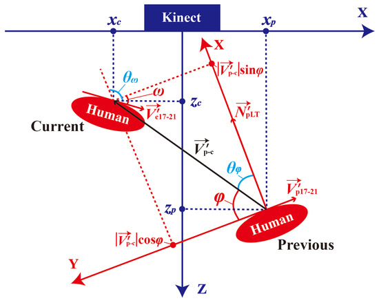
Figure 9.
The calculation of the displacement and rotation angle between two adjacent locomotion loops. The blue coordinate axes correspond to the Kinect frame, and the red coordinate axes correspond to the human base frame.
Because the locomotion of the robot should be controlled in the robot’s base frame, of which the x-axis points forward, the y-axis points rightward and the z-axis projects vertically between the two feet and points upward, the data captured in the Kinect frame should first be mapped to the human base frame. The human base frame is defined to be the same as the robot’s base frame.
3.5.1. Body Rotation
The vector pointing from Hip_Left (point 17) to Hip_Right (point 21), , is introduced as the reference for the rotations of the human body. The corresponding vectors, denoted by for the current locomotion loop and for the previous one, are obtained for every pair of adjacent locomotion loops. Then, and are projected onto the horizontal plane (the x–z plane in the Kinect frame) to eliminate the errors caused by vertical deviations. The projections are denoted by and , respectively, and the angle between these two vectors, , is calculated as
where and are collinear with the y-axes of the corresponding human base frames, as shown in Figure 9.
To determine whether the robot should turn clockwise or counterclockwise, the vector representing the direction of the lower torso on the horizontal plane in the previous locomotion loop, , is introduced as follows:
where is a vertically upward vector. is also collinear with the x-axis of the previous human base frame, as seen from Figure 9. Then, the angle is introduced as follows:
Thus, can be obtained as follows:
A positive value means that the human demonstrator is turning counterclockwise, whereas a negative value means that the demonstrator is turning clockwise. If meets or exceeds a threshold value , the robot will rotate with angle .
3.5.2. Displacement
The position of the Spine_Base skeleton point (point 0) is regarded as the position of the demonstrator. The vector pointing from the previous position of the Spine_Base point to the current position of Spine_Base is represented by . After the errors caused by vertical deviations of the Spine_Base point have been eliminated, the distance between the positions of the human demonstrator in two adjacent locomotion loops can be obtained as follows:
where is the projection of onto the horizontal plane, is the x-coordinate of the Spine_Base point in the Kinect frame in the current locomotion loop, and is the x-coordinate of the Spine_Base point in the Kinect frame in the previous locomotion loop. Similarly, is the z-coordinate of Spine_Base in the Kinect frame in the current locomotion loop, and is the previous z-coordinate. Then, we can obtain the angle as depicted in Figure 9, using the same approach as for the calculation of . First, the angle between and is introduced as follows:
Then, can be obtained as follows:
Thus, we can obtain
where is the displacement along the x-axis of the human base frame and is the displacement along the y-axis of the human base frame. For convenience in task execution, we directly apply the displacements of the human demonstrator to the robot.
The displacement of the human’s left foot between two adjacent locomotion loops, , and the displacement of the right foot, , are both considered. If both and meet or exceed a threshold value of , then the robot will enter the walking mode to execute locomotion with the corresponding displacement.
3.6. Discussion of Extension to Other Humanoids
The existing humanoid robots are inspired and developed in imitation of human being’s body, such as DARwIn [52] and Asimo [53], so their overall configurations are usually similar, especially the joints of shoulders, elbows, hips and knees. These joints mainly decide the postures of a humanoid robot. Since the proposed motion mapping methods are based on human being’s motion information and general characteristics of humanoid robots, it can be extended to other types of humanoid robots.
In terms of GA-LVVJ, after the link vectors are constructed, the virtual joints should be always set in accordance with the robot agent. Then, the link frames can be defined. When calculating joint angles, if there are no more than two virtual joints between two link vectors, such as the human skeleton models corresponding to NAO and DARwIn, the calculation of this type of humanoid robots is the same as that described in Section 3.2. If there are more than two virtual joints between two link vectors, such as the shoulder joints and the hip joints corresponding to Asimo, the DOFs of these joints are redundant, and thus multiple solutions exist. In this case, the unique solution can be obtained if the virtual joints’ second child link is considered. For example, the link vector of a lower arm link can help decide the shoulder joint angles, and the link vector of a tibia can help decide the hip joint angles.
For head motion mapping, the algorithm used in our system can extract pitch, roll and yaw angles of the neck, which can meet the needs of most humanoid robots.
For hand motion mapping, if humanoid robots, such as Asimo, have dexterous hands with multiple DOFs, more effective algorithms of gesture recognition are then needed for dexterous hand motions.
With respect to locomotion mapping, when it is extended to other types of humanoid robots and mobile robots, the rotation and displacement mapping is the same while the calculation of gaits or moving strategies can be different.
4. Mode Switch
The proposed system includes three modes, i.e., the single-support mode, the double-support mode and the walking mode. To ensure that the robot will switch to the correct mode with only inputs in the form of natural human motions rather than requiring additional postures or other devices and to reduce wobble, a filter strategy is employed. In addition, to ensure the balance and stability of the robot during mode switching, some transition motions are applied.
4.1. Filter Strategy
Our proposed filter strategy has two purposes. First, it is used to ensure that the robot switches to the correct mode through repeated detection and error filtering. Second, the filter strategy is employed to filter unstable motions before the mode changes. Details are presented in the following subsections.
4.2. Double-Support Mode to Single-Support Mode
In the double-support mode, the robot’s feet are flat and limited to the horizontal plane, and they can move on the ground. When the human demonstrator lifts one foot such that the height threshold is reached in three consecutive motion loops, the robot will lean toward the side corresponding to the supporting leg and shift its center of mass over the resulting single-support polygon. During the shifting of the center of mass, the robot’s feet are statically fixed on the ground for stability. After the shifting motions are finished, the robot’s foot will be lifted, and the imitation motions will be executed. In the single-support phase, the supporting foot is fixed.
When a human in walking with a normal gait, he or she will similarly lift his or her left and right feet to some low height by turns, which will also generate height differences. After all, the lifting of one foot in the single-support mode can be regarded as a short-duration part of the process of stepping in the walking mode. Therefore, to avoid the situation in which the humanoid robot may mistakenly enter the single-support mode when the demonstrator starts to walk, the humanoid robot is constrained to lift its foot only if the height threshold is reached in at least three consecutive motion loops. In addition, occasional leaping errors caused by the RGB-D camera are prevented from triggering the wrong mode in this way. This approach results in a slight delay, but it can ensure that the robot will not enter the wrong motion mode. Based on the experimental results, of our system is set to 5 cm, which is much smaller than the height threshold in the work reported in [24].
Although leaping errors do occur, most of the time, the detected height difference is less than a small value when both feet are on the ground. The execution of lower-limb motions in the double-support mode is filtered to occur only when the height difference is greater than . In this way, any wobbling of the robot before the lifting of the foot will be alleviated. Such wobbles are expected to be caused by attempts to imitate the motion of the lifted human leg before the height threshold of the single-support mode is reached.
4.3. Double-Support Mode to Walking Mode
When the displacements of both feet or the rotation angle of the human demonstrator reach the threshold or respectively at the start of one locomotion loop, the humanoid robot will enter the walking mode. Several preset walking gaits are specified for use in reaching the required displacement and rotation angle. The displacement threshold must be met by both feet because it may occur that the human demonstrator will reach out with one foot without intending to walk, in which case the robot should remain in the double-support mode. In addition, the threshold should not be set too small to avoid undesired effects of the errors of the RGB-D camera and tiny movements or wobbles of the human demonstrator during the double-support phase.
The displacements of both feet are also detected in every motion loop. If a small displacement of either foot is detected, the execution of lower-limb imitation in this motion loop will be stopped. The activation will be delayed to the next motion loop in which no such displacement is detected. This approach is used to filter out imitation of a reaching-out leg motion and to alleviate instability when the demonstrator starts to walk while the robot is still in the double-support phase, thus contributing to safe switching into the walking mode.
4.4. Single-Support Mode to Double-Support Mode
When the human demonstrator is standing on one foot and then places his or her free foot on the ground, if the free foot is detected to be below the height threshold for three consecutive motion loops, then the humanoid robot will begin to transition into the double-support mode. This requirement of three consecutive threshold checks is established to avoid leaping errors. To ensure that the swing foot lands safely, its orientation is first set parallel to the ground, and the leg angles are then changed to place it on the ground. The swing foot is kept parallel to the ground, and the whole-body balancer is also employed during this period.
5. Balance Control
Due to the differences in body configuration and weight distribution between the human demonstrator and the humanoid robot, direct application of the human joint angles as the target joint angles of the robot may cause it to fall down, especially when the robot is in the single-support phase. To maintain balance, the center of mass of the robot must be kept centered over the support polygon. The support polygon here is the convex hull of the footprint. Because of the difference in dynamic features between the robot and the human body, and, for simplicity, we discuss only the problem of balance control under the action of gravity, and the imitation process is treated as a quasi-static process; i.e., the state in each moment is considered to be a static state.
The balance control strategy we have used is based on the quadratic programming (QP) method. We suppose that denotes the joint angle vector of a target pose for imitation. The joint angles of the target pose are acquired from the pose of the human skeleton model using the GA-LVVJ method and the head motion mapping method. The joint angle vector of a stable pose is denoted as , which is obtained through the balance control. The stable pose will directly applied to the robot instead of the target pose. To ensure that is close to , the problem can be described as a QP problem on the velocity level, i.e.,
where denotes the unknown joint angle velocity vector, denotes the joint angle velocity vector of the target pose acquired from the derivative of ; is a matrix that expresses linear equality constraints, is a vector that expresses linear equality constraints; is a matrix that expresses linear inequality constraints, and is a vector that expresses linear inequality constraints. n is the dimension of the joint space, l is the dimension of the equality constraints, and m is the dimension of the inequality constraints. The equality constraints are used to keep the feet fixed or in a plane, and the inequality constraints are used to constrain the projection of the center of mass within the corresponding support polygon.
Taking the single support as an example, to keep the projection of the center of mass (COM) in the support polygon, the convex hull of the robot support foot can be simplified as an rectangle. As the support foot is fixed during single-support phase, the link frame of the support foot can be set as the world frame, and each side of the rectangle is parallel to the x-axis or the y-axis of the world frame. The position of the robot COM in the world frame can be expressed as:
Using the Jacobian matrix introduced in [54], the velocity of the COM (referred as center of gravity in [54]) can establish relations with the velocity of joint angles :
By defining , and as the row vectors of , Equation (38) can be expressed as:
When the projection of the COM has been put in the rectangle, by defining the range of the rectangle along the x-axis and y-axis as and , respectively, and the safety threshold as , the constraints regarding of the QP problem can be obtained:
On the NAO robot, this QP problem is solved every 20 ms. Once the optimal solution is got, can be obtained from the integral of and applied to the robot, and thus stable and similar imitation motions can be achieved in real time.
6. Similarity Evaluation
To quantitatively evaluate the robot’s motion similarity in the single- or double-support mode, the robot’s pose at a given moment is compared with that of the human demonstrator which is represented by the human skeleton model. The vectors representing the robot’s pose can be obtained from a forward kinematics calculation using joint angles, whereas the vectors representing the human body are link vectors of the human skeleton model, which are constructed based on the skeleton points captured by the RGB-D camera. The evaluation is inspired by the correlation coefficient between two variable vectors introduced in [55]:
where denotes the correlation coefficient between vectors i and j and denotes the angle between vectors i and j. Considering the cognitive differences between different situations, two similarity evaluation methods are proposed as follows.
6.1. Whole-Body-Focused (WBF) Method
In the first similarity evaluation method, the similarity is evaluated based on the overall perception of the whole body with the ground as the reference. This method considers the positions and poses of the body links in the world frame.
In practice, the base frame of the robot is rotated and translated to coincide with that of the human for similarity evaluation, which is regarded as the world frame. The vectors which represent the robot’s pose are rotated and translated with the base frame of the robot. The correlation coefficient between one robot vector and the corresponding human vector in the world frame, , is
where is the angle between the two corresponding vectors in the world frame.
In the proposed method, the vectors of the two upper arms, the two lower arms, the two thighs (upper legs), the two tibias (lower legs), the torso and the head are considered. Because the feet have only a slight influence on the similarity and the detection precision for the human’s feet is relatively low, the vectors of the two feet are not considered. Therefore, the correlation coefficient between the postures of the robot and the human using the WBF method is
where is taken to be the similarity index of the WBF evaluation method.
6.2. Local-Link-Focused (LLF) Method
In the first proposed metric, chances are that the posture of a chain of links (such as an arm chain consisting of an upper-arm link and a lower-arm link) of the robot in the world frame look will very similar to that of the human, but the corresponding values of the link correlation coefficients will nevertheless be quite low because the mother link in the robot chain (such as the upper-arm link in an arm chain) may deviate from the direction of the corresponding human link in the world frame. For example, the directions of some robot mother links may be modified considerably to maintain balance, and, thus, all of the child links will be affected. Therefore, the local posture similarity cannot be properly assessed when using the WBF method. However, the local motions of certain links will be more important than whole-body motions under some circumstances. For example, human observers will pay more attention to the arms and upper torso of the demonstrator when they wish to learn arm movements in a dance class. Therefore, to enable the similarity metric to reflect the effects of local postures, a link vector of the human or the robot should be transformed into the link frame of its own mother link. When calculating the correlation coefficient of two vectors, the two link frames of the mother links of this pair of corresponding vectors are translated and rotated to coincide with each other and are unified as one frame. Meanwhile, the link vectors are translated and rotated with the link frames of their mother links, respectively. Then, the correlation coefficient between one robot vector and the corresponding human vector in the unified frame, , is
where denotes the angle between two corresponding vectors in their unified frame.
Thus, the correlation coefficient between the postures of the robot and the human using the LLF evaluation method is
where is also the similarity index of the LLF evaluation method.
In the experimental section, the two metrics proposed here will be applied to evaluate the similarities of whole-body and local-link features, respectively.
7. Experiment
To validate the effectiveness of the proposed imitation system and evaluate the imitation similarity, two motion imitation experiments were conducted. The joint angles of the robot and the human skeleton model which represents the human demonstrator were tracked, and the similarity indexes of both the WBF and LLF evaluation methods were calculated for each motion loop. In addition, the proposed system was applied for teleoperation to perform a task. The task required grabbing and releasing objects in both the double- and single-support modes, and it also required the robot to move to a target location. Since it is very hard to get wrist rotations from the human skeleton model, in the experiment, the wrist joint angles of the NAO robot were set to fixed values.
7.1. Real-Time Whole-Body Imitation of Singly and Doubly Supported Motions
In this experiment, the demonstrator performed a series of motions that included both doubly supported motions and singly supported motions. Snapshots of this experiment are shown in Figure 10, where the numbers denote the motion loop ordinal number of each snapshot. The double-support phase corresponded to the 1st motion loop through the 85th motion loop. During this period, the main motions of the demonstrator were movements of the right arm. The mode-switch phase corresponded to the 85th motion loop through the 100th motion loop. The demonstrator lifted his left foot, and the robot moved its center of mass to the right side and lifted its left foot. The single-support phase lasted from the 100th motion loop to the end. The demonstrator performed a sequence of singly supported postures, some of which made it difficult for even the human demonstrator to maintain his balance. The results and analysis of this experiment are as follows.
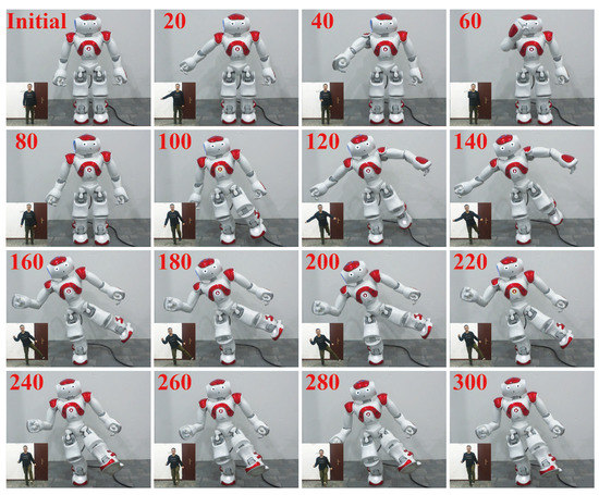
Figure 10.
Snapshots of the robot and the human demonstrator in the first experiment. The red numbers are the ordinal numbers of the motion loops, of which the average duration is 0.26 s.
7.1.1. Computational Cost
The average computational cost of the posture mapping (calculation of the target joint angles of the robot) was 0.033 ms, much lower than that of typical numerical IK solvers such as [21], which requires 1.04 ms for posture mapping on average.
7.1.2. Error Analysis
We compared the joint angles of the robot and the human skeleton model in real time and the errors were computed in every motion loop. The average and maximum errors between key joint angles in the human skeleton model and the robot are listed in Table 1, where the letters “D”, “S”, and * indicate that the maximum errors occurred in the double-support phase, the single-support phase and the mode-switch phase, respectively. As seen from Table 1, the average errors are very small, and the maximum errors are reasonable, thereby verifying the effectiveness of the proposed real-time imitation system. The observed errors are attributed to the following causes: (1) The delay of the robot’s motions will lead to angle deviations; (2) Joint angles will be modified when the original target angles do not satisfy the balance conditions for a stable pose; (3) The robot’s joint limits will restrict some postures; (4) During the mode-switch phase (from the double-support mode to the single-support mode), the robot cannot lift its foot immediately after the human’s foot reaches the threshold height for stability; (5) Due to the error of the Kinect II, the joint angles extracted from the detected data of the same joint between two motion loops may show a leaping deviation, whereas the robot’s joint angles vary continuously.

Table 1.
Average and maximum errors of key joint angles. The errors between the robot and the human skeleton model were computed in each motion loop.
7.1.3. Consistency of Joint Angle Trajectories
The angle trajectories of several key joints are depicted in Figure 11 and Figure 12. Although there are some small deviations, the trajectory curves show good joint angle consistency between the robot and the human skeleton model. From the 1st motion loop to the 85th motion loop (double-support phase), the uniformity of the joint angle trajectories between the human skeleton model and the robot is good, and the deviations are almost invisible in most trajectories. The deviations of the LShoulderRoll angle are due to the self-collision avoidance of the robot. From the 85th motion loop to the 100th motion loop (mode-switch phase), the center-of-mass transference and the filter strategy introduce an obvious delay in lifting the left foot. This delay is evident in the angle trajectories of LHipRoll, LHipPitch and LKneePitch (Figure 11d–f). As shown in Table 1, these three joint angles’ maximum errors occur during the mode-switch phase and are among the largest of the maximum errors. From the 100th motion loop to the end (single-support phase), because the balance of the singly supported postures is mainly maintained by the right leg, the angles of RHipRoll, RHipPitch, and RKneePitch exhibit obvious deviations, as seen in Figure 12a–c. These joint angles are modified to maintain balance. The maximum errors of these three joint angles appear in the single-support phase, but the values are quite low. From the 255th motion loop to the end, there are obvious fluctuations and errors in the RElbowRoll angle. This is because the right lower arm of the demonstrator obscured the RGB-D camera’s view of the right elbow. The other joint angle trajectories during this period show good uniformity.
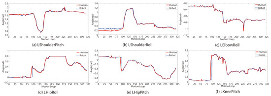
Figure 11.
Left key joint angle trajectories of the human and the robot in the first experiment. (a)–(f) depict the joint angle trajectories of LShoulderPitch, LShoulderRoll, LElbowRoll, LHipRoll, LHipPitch and LKneePitch, respectively.
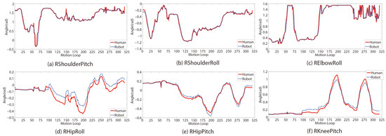
Figure 12.
Right key joint angle trajectories of the human and the robot in the first experiment. (a)–(f) depict the joint angle trajectories of RShoulderPitch, RShoulderRoll, RElbowRoll, RHipRoll, RHipPitch and RKneePitch, respectively.
7.1.4. Similarity Evaluation
The similarity indexes of the WBF method and the LLF method were applied to evaluate our imitation system in real time. The trajectories of both indexes are shown in Figure 13. In the double-support phase, the WBF similarity index is above 0.94, and the LLF index is above 0.98. The variation trends of the two curves are similar, and the value of the LLF index is higher than that of the WBF index. From the 55th motion loop to the 70th motion loop, the similarity index curves show obvious fluctuations because of the slight delay in the movements of the robot’s right arm. This slight delay can be observed from the RShoulderPitch angle trajectories (Figure 12a). During the mode-switch phase, both similarity index curves dip down and form troughs. However, the index values remain above 0.93. In the single-support phase, the WBF similarity index shows a decline compared with that in the double-support phase, whereas the LLF index returns to a high level. GA-LVVJ considers the local geometrical relations between articulated links and obtains the joint angles of the imitated posture directly and accurately, thereby contributing to the excellent observed performance in terms of local posture similarity.
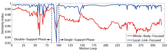
Figure 13.
Similarity index trajectories in the first experiment as calculated using the two evaluation methods.
In the WBF method, in which the ground is regarded as the reference, if the robot is standing on its right foot, then the right tibia is the mother link of the right thigh and the right thigh is the mother link of the torso. In turn, the torso is the mother link of the upper links of the other limbs, which are the mother links of their respective lower links. Thus, the deviations of the mother links will accumulate and affect the positions of their child links in the world frame, even if their local similarity is high. This phenomenon will be more evident during the single-support phase because the links of the supporting leg, which serve as the mother links of the other parts, may deviate considerably to maintain balance. As shown in Figure 14 and Figure 15, in the right-support phase, because the right leg angles are considerably modified to maintain balance, the left-thigh WBF similarity index shows an evident decline in the single-support phase compared with the double-support phase. Because the left tibia is the child link of the left thigh, the left-tibia WBF similarity index shows a sharper decline than that of the left thigh. Furthermore, the decline will be more evident when the single-support posture is more challenging. However, with a lowest value above 0.94, the WBF similarity index still indicates good performance in terms of the imitation similarity as seen from the perspective of the world frame.

Figure 14.
Left-thigh similarity index trajectories in the first experiment as calculated using the two evaluation methods.
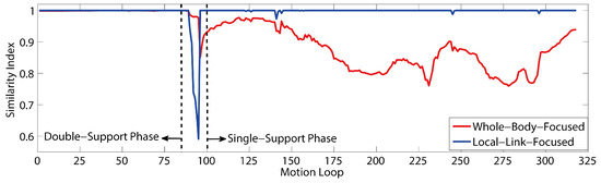
Figure 15.
Left-tibia similarity index trajectories in the first experiment as calculated using the two evaluation methods.
In short, this experiment verifies that the joint angle consistency between the human demonstrator and the robot is high and that our system performs well in terms of both the local similarity and the whole-body similarity.
7.1.5. Test on Different Human Body Shapes
The system has been tested on five human demonstrators with different body shapes as shown in Figure 16. Still, even difficult single-support motions can be imitated by the robot stably and continuously, which verifies the effectiveness of the proposed methods.
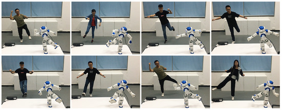
Figure 16.
Snapshots of some difficult single-support motions that the robot can perform by imitating human demonstrators with different body shapes.
7.2. Task-Oriented Teleoperation
In this subsection, we report the use of our system to manipulate the robot to place two pens into two different containers. The experimental setting is shown in Figure 17. The robot was placed at a location in the room where the demonstrator could not see it. A Kinect II RGB-D camera was employed to capture the motions of the human demonstrator. The first-person perspective of the robot was captured by the robot’s head-mounted camera, and the third-person perspective of the overall task situation was monitored by an RGB camera; both video feeds were shown on the screen to provide views of the task in real time.
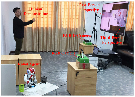
Figure 17.
The real-time imitation system used in the task-oriented teleoperation experiment.
The initial position of the robot dictated that the robot should seize the pens in its right hand. However, the containers were out of range of the robot’s right arm when the robot was in the double-support mode, as depicted in Figure 18a,c. The left arm was not used to reach the black container because it was not convenient to transfer the pen from the right hand to the left hand. Thus, two approaches were employed to reach the containers out of range of the robot’s arm. To reach the green container, the robot was required to lift its left foot and lean rightward to cover a longer distance, as shown in Figure 18b. To reach the black container, the robot was required to walk leftward, as shown in Figure 18d.
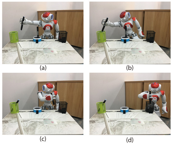
Figure 18.
Description of the teleoperation task; (a) shows that the robot cannot reach the green container in the double-support mode; (b) shows that when the robot leans rightward in the single-support mode, it can easily reach the container; (c) shows that the robot cannot reach the black container in the double-support mode; (d) shows that when the robot walks leftward, it can easily reach the container.
In the experiment, the robot imitated a series of motions performed by the human demonstrator and successfully placed the pens into the containers. A–H in Figure 19 show snapshots of the motions of the human and the robot during the process of placing the blue pen into the right green container. I–P in Figure 19 show snapshots of the motions of the human and the robot during the process of placing the pink pen into the left black container.
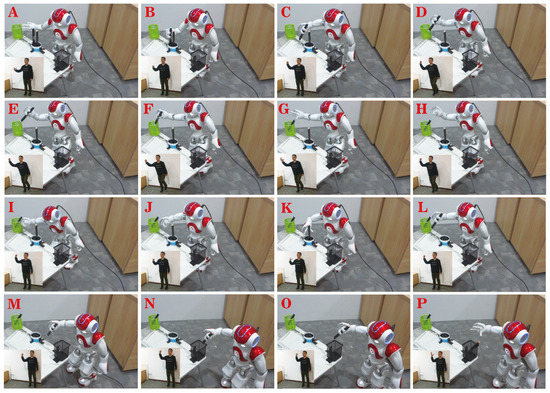
Figure 19.
Snapshots of the robot and the human in the task-oriented teleoperation experiment.
This teleoperation experiment verifies that the proposed imitation system can be applied to execute real-time teleoperation tasks stably and effectively.
8. An Imitation Learning Case
Imitation learning is an efficient learning mechanism for reducing the complexity of search spaces and accelerating learning [56]. As shown in Figure 20, a hello motion is demonstrated by five different demonstrators. In each demonstration, the moving arm’s joint angles mapped through GA-LVVJ are recorded with their corresponding temporal information. Each dataset of a certain joint is aligned temporarily and scaled to a fixed time step. Then, the datasets are encoded by Gaussian Mixture Model (GMM), and a generalized joint angle trajectory is produced through Gaussian Mixture Regression (GMR) [57]. Thus, the robot can learn from multiple demonstrations of the hello motion and reproduce a new one.
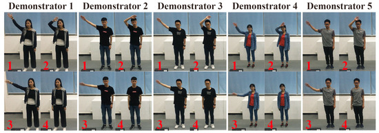
Figure 20.
The snapshots of the hello motion performed by five demonstrators.
First, the datasets of different demonstrators are aligned temporarily using Dynamic Time Wrapping (DTW) [58] to improve the coherence of data; then, the data of each demonstration is scaled to 100 time steps. The dataset of a joint denotes N observations of , where is a temporal value and is a joint angle. Then, the dataset is modeled by a GMM of K components, and each data point is define by the probability density function
where denotes the prior probability of component k, and denotes the Gaussian distribution whose mean vector and covariance matric are and , respectively. The temporal and angular components of and can be represented separately as
Then, a generalized joint angle trajectory can be obtained by applying GMR as follows. For each component k, the expected distribution of the angular value given the temporal value is defined by
Considering the complete GMM, the expected distribution of given is defined by
where is the probability of the component k given , i.e.,
Then, the expected distribution of given is , where the parameters of the Gaussian distribution are
Therefore, by evaluating , a generalized joint angle trajectory and associated covariance matrix can be obtained.
This process is shown in Figure 21. The reproduced hello motion performed by NAO is depicted in Figure 22, which demonstrates the key features of a hello motion effectively.
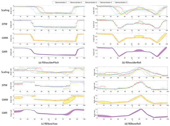
Figure 21.
The imitation learning process of the hello motion. The first figure of each joint angle (i.e., RShoulderPitch, RShoulderRoll, RElbowYaw or RElbowRoll) depicts the scaling result of the raw datasets. The second figure depicts the DTW and scaling result of the datasets. The third one depicts the GMM encoding result. The fourth one depicts the generalized angle trajectory produced by GMR.
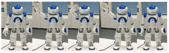
Figure 22.
The snapshots of the reproduced hello motion performed by NAO.
9. Conclusions
In this paper, a novel real-time whole-body imitation system for humanoid robots has been proposed. To map the motions of a human demonstrator to a robot, a novel analytical method called GA-LVVJ has been proposed. In addition, a real-time locomotion method has been employed during the walking phase for convenience in completing tasks. To enable accurate and safe mode switching, we have presented a filter strategy to eliminate leaping errors and alleviate wobble. In addition, two quantitative methods of similarity evaluation focusing on the whole body and local links, called the WBF method and the LLF method, respectively, have been proposed and compared. The results of two experiments verify the effectiveness of the proposed imitation system. The first experiment has demonstrated the good stability and high similarity achieved during single-support and double-support imitation. The second experiment has validated the capability to execute tasks via real-time teleoperation using the proposed system. Finally, an imitation learning mechanism in which the joint angles of demonstrators are mapped by GA-LVVJ is presented and developed to extend the proposed system.
Author Contributions
Conceptualization, Z.Z. and Y.N.; Methodology, Y.N.; Software, Y.N. and S.L.; Validation, Z.Z., Y.N. and Z.Y.; Formal Analysis, Y.N.; Investigation, Y.N.; Resources, Z.Z.; Data Curation, Y.N.; Writing and Original Draft Preparation, Y.N.; Writing and Review and Editing, Z.Z., Y.N. and Z.Y.; Visualization, Y.N.; Supervision, Z.Z.; Project Administration, Z.Z.; Funding Acquisition, Z.Z. and Y.N.
Funding
This research was funded in part by the National Key R&D Program of China under Grant 2017YFB1002505, the National Natural Science Foundation of China under Grants 61603142 and 61633010, the Guangdong Foundation for Distinguished Young Scholars under Grant 2017A030306009, the Guangdong Youth Talent Support Program of Scientific and Technological Innovation under Grant 2017TQ04X475, Science and Technology Program of Guangzhou under Grant 201707010225, the Fundamental Research Funds for Central Universities under Grant 2017MS049, the Scientific Research Starting Foundation of South China University of Technology, the National Key Basic Research Program of China (973 Program) under Grant 2015CB351703, and the Natural Science Foundation of Guangdong Province under Grant 2014A030312005.
Conflicts of Interest
The authors declare no conflict of interest.
Abbreviations
The following abbreviations are used in this manuscript:
| GA-LVVJ | Geometrical Analysis Based on Link Vectors and Virtual Joints |
| WBF | Whole-Body-Focused |
| LLF | Local-Link-Focused |
| IK | Inverse kinematic |
| LUT | Left upper torso |
| LSP | LShoulderPitch |
| LSR | LShoulderRoll |
| LUA | Left upper arm |
| LEY | LElbowYaw |
| LER | LElbowRoll |
| LLT | Left lower torso |
| LHR | LHipRoll |
| LHP | LHipPitch |
| LTh | Left thigh |
| DOF | Degree of freedom |
| LKP | LKneePitch |
| LT | Lower torso |
| QP | Quadratic programming |
| GMM | Gaussian Mixture Model |
| GMR | Gaussian Mixture Regression |
| DTW | Dynamic Time Wrapping |
References
- Morita, T.; Mase, K.; Hirano, Y.; Kajita, S. Reciprocal attentive communication in remote meeting with a humanoid robot. In Proceedings of the 9th International Conference on Multimodal Interfaces, Nagoya, Japan, 12–15 November 2007; pp. 228–235. [Google Scholar]
- Qi, R.; Khajepour, A.; Melek, W.W.; Lam, T.L.; Xu, Y. Design, Kinematics, and Control of a Multijoint Soft Inflatable Arm for Human-Safe Interaction. IEEE Trans. Robot. 2017, 33, 594–609. [Google Scholar] [CrossRef]
- Ferraguti, F.; Preda, N.; Manurung, A.; Bonfe, M.; Lambercy, O.; Gassert, R.; Muradore, R.; Fiorini, P.; Secchi, C. An energy tank-based interactive control architecture for autonomous and teleoperated robotic surgery. IEEE Trans. Robot. 2015, 31, 1073–1088. [Google Scholar] [CrossRef]
- Marescaux, J.; Leroy, J.; Rubino, F.; Smith, M.; Vix, M.; Simone, M.; Mutter, D. Transcontinental robot-assisted remote telesurgery: Feasibility and potential applications. Ann. Surg. 2002, 235, 487–492. [Google Scholar] [CrossRef] [PubMed]
- Meng, C.; Zhang, J.; Liu, D.; Liu, B.; Zhou, F. A remote-controlled vascular interventional robot: System structure and image guidance. Int. J. Med. Robot. Comput. Assist. Surg. 2013, 9, 230–239. [Google Scholar] [CrossRef] [PubMed]
- Butner, S.E.; Ghodoussi, M. Transforming a surgical robot for human telesurgery. IEEE Trans. Robot. Autom. 2003, 19, 818–824. [Google Scholar] [CrossRef]
- Atashzar, S.F.; Polushin, I.G.; Patel, R.V. A Small-Gain Approach for Nonpassive Bilateral Telerobotic Rehabilitation: Stability Analysis and Controller Synthesis. IEEE Trans. Robot. 2017, 33, 49–66. [Google Scholar] [CrossRef]
- Nielsen, C.W.; Goodrich, M.A.; Ricks, R.W. Ecological interfaces for improving mobile robot teleoperation. IEEE Trans. Robot. 2007, 23, 927–941. [Google Scholar] [CrossRef]
- Bakker, P.; Kuniyoshi, Y. Robot see, robot do: An overview of robot imitation. In Proceedings of the AISB96 Workshop on Learning in Robots and Animals, Brighton, UK, 1–2 April 1996; pp. 3–11. [Google Scholar]
- Riley, M.; Ude, A.; Wade, K.; Atkeson, C.G. Enabling real-time full-body imitation: A natural way of transferring human movement to humanoids. In Proceedings of the IEEE International Conference on Robotics and Automation (ICRA), Taipei, China, 14–19 September 2003; Volume 2, pp. 2368–2374. [Google Scholar]
- Zhao, X.; Huang, Q.; Peng, Z.; Li, K. Kinematics mapping and similarity evaluation of humanoid motion based on human motion capture. In Proceedings of the IEEE/RSJ International Conference on Intelligent Robots and Systems (IROS), Vancouver, BC, Canada, 24–28 September 2004; Volume 1, pp. 840–845. [Google Scholar]
- Gu, Y.; Thobbi, A.; Sheng, W. Human-robot collaborative manipulation through imitation and reinforcement learning. In Proceedings of the IEEE International Conference on Information and Automation (ICIA), Jeju Island, Korea, 19–21 August 2011; pp. 151–156. [Google Scholar]
- Liu, H.Y.; Wang, W.J.; Wang, R.J.; Tung, C.W.; Wang, P.J.; Chang, I.P. Image recognition and force measurement application in the humanoid robot imitation. IEEE Trans. Instrum. Meas. 2012, 61, 149–161. [Google Scholar] [CrossRef]
- Tomić, M.; Chevallereau, C.; Jovanović, K.; Potkonjak, V.; Rodić, A. Human to humanoid motion conversion for dual-arm manipulation tasks. Robotica 2018, 1–21. [Google Scholar] [CrossRef]
- Cheng, G.; Kuniyoshi, Y. Real-time mimicking of human body motion by a humanoid robot. In Proceedings of the 6th Intelligent Autonomous Systems, Venice, Italy, 25–27 July 2000; pp. 273–280. [Google Scholar]
- Hwang, C.L.; Chen, B.L.; Syu, H.T.; Wang, C.K.; Karkoub, M. Humanoid Robot’s Visual Imitation of 3-D Motion of a Human Subject Using Neural-Network-Based Inverse Kinematics. IEEE Syst. J. 2016, 10, 685–696. [Google Scholar] [CrossRef]
- Sakka, S.; Poubel, L.P.; Cehajic, D. Tasks prioritization for whole-body realtime imitation of human motion by humanoid robots. In Proceedings of the Digital Intelligence (DI2014), Nantes, France, 17–19 September 2014; p. 5. [Google Scholar]
- Kondo, Y.; Yamamoto, S.; Takahashi, Y. Real-time Posture Imitation of Biped Humanoid Robot based on Particle Filter with Simple Joint Control for Standing Stabilization. In Proceedings of the Joint 8th International Conference on Soft Computing and Intelligent Systems (SCIS) and 17th International Symposium on Advanced Intelligent Systems, Toyama, Japan, 5–8 December 2016; pp. 130–135. [Google Scholar]
- Filiatrault, S.; Cretu, A.M. Human arm motion imitation by a humanoid robot. In Proceedings of the IEEE International Symposium on Robotic and Sensors Environments (ROSE), Timisoara, Romania, 16–18 October 2014; pp. 31–36. [Google Scholar]
- Chen, J.; Wang, G.; Hu, X.; Shen, J. Lower-body control of humanoid robot NAO via Kinect. Multimedia Tools Appl. 2018, 77, 10883–10898. [Google Scholar] [CrossRef]
- Koenemann, J.; Burget, F.; Bennewitz, M. Real-time imitation of human whole-body motions by humanoids. In Proceedings of the IEEE International Conference on Robotics and Automation (ICRA), Hong Kong, China, 31 May–7 June 2014; pp. 2806–2812. [Google Scholar]
- Avalos, J.; Cortez, S.; Vasquez, K.; Murray, V.; Ramos, O.E. Telepresence using the kinect sensor and the NAO robot. In Proceedings of the IEEE 7th Latin American Symposium on Circuits & Systems (LASCAS), Florianopolis, Brazil, 28 February–2 March 2016; pp. 303–306. [Google Scholar]
- Ou, Y.; Hu, J.; Wang, Z.; Fu, Y.; Wu, X.; Li, X. A real-time human imitation system using kinect. Int. J. Soc. Robot. 2015, 7, 587–600. [Google Scholar] [CrossRef]
- Poubel, L.P.; Sakka, S.; Ćehajić, D.; Creusot, D. Support changes during online human motion imitation by a humanoid robot using task specification. In Proceedings of the IEEE International Conference on Robotics and Automation (ICRA), Hong Kong, China, 31 May–7 June 2014; pp. 1782–1787. [Google Scholar]
- Zuher, F.; Romero, R. Recognition of human motions for imitation and control of a humanoid robot. In Proceedings of the Robotics Symposium and Latin American Robotics Symposium (SBR-LARS), Fortaleza, Brazil, 16–19 October 2012; pp. 190–195. [Google Scholar]
- Lei, J.; Song, M.; Li, Z.N.; Chen, C. Whole-body humanoid robot imitation with pose similarity evaluation. Signal Process. 2015, 108, 136–146. [Google Scholar] [CrossRef]
- Lee, J.H. Full-body imitation of human motions with kinect and heterogeneous kinematic structure of humanoid robot. In Proceedings of the IEEE/SICE International Symposium on System Integration (SII), Fukuoka, Japan, 16–18 December 2012; pp. 93–98. [Google Scholar]
- Franz, S.; Nolte-Holube, R.; Wallhoff, F. NAFOME: NAO Follows Me-Tracking, Reproduction and Simulation of Human Motion; Jade University of Applied Sciences: Wilhelmshaven, Germany, 2013. [Google Scholar]
- Almetwally, I.; Mallem, M. Real-time tele-operation and tele-walking of humanoid robot NAO using Kinect depth camera. In Proceedings of the 10th IEEE International Conference on Networking, Sensing and Control (ICNSC), Paris-Evry, France, 10–12 April 2013; pp. 463–466. [Google Scholar]
- Aleotti, J.; Skoglund, A.; Duckett, T. Position teaching of a robot arm by demonstration with a wearable input device. In Proceedings of the International Conference on Intelligent Manipulation and Grasping (IMG04), Genova, Italy, 1–2 July 2004; pp. 1–2. [Google Scholar]
- Calinon, S.; Billard, A. Incremental learning of gestures by imitation in a humanoid robot. In Proceedings of the ACM/IEEE International Conference on Human-Robot Interaction, Washington, DC, USA, 9–11 March 2007; pp. 255–262. [Google Scholar]
- Asfour, T.; Azad, P.; Gyarfas, F.; Dillmann, R. Imitation learning of dual-arm manipulation tasks in humanoid robots. Int. J. Humanoid Robot. 2008, 5, 183–202. [Google Scholar] [CrossRef]
- Liu, X.; Zhou, X.; Liu, C.; Wang, J.; Zhou, X.; Xu, N.; Jiang, A. An interactive training system of motor learning by imitation and speech instructions for children with autism. In Proceedings of the 9th IEEE International Conference on Human System Interactions (HSI), Krakow, Poland, 25–27 May 2016; pp. 56–61. [Google Scholar]
- Boucenna, S.; Anzalone, S.; Tilmont, E.; Cohen, D.; Chetouani, M. Learning of social signatures through imitation game between a robot and a human partner. IEEE Trans. Auton. Ment. Dev. 2014, 6, 213–225. [Google Scholar] [CrossRef]
- Rozo, L.; Calinon, S.; Caldwell, D.G.; Jimenez, P.; Torras, C. Learning physical collaborative robot behaviors from human demonstrations. IEEE Trans. Robot. 2016, 32, 513–527. [Google Scholar] [CrossRef]
- Alibeigi, M.; Ahmadabadi, M.N.; Araabi, B.N. A fast, robust, and incremental model for learning high-level concepts from human motions by imitation. IEEE Trans. Robot. 2017, 33, 153–168. [Google Scholar] [CrossRef]
- Stephens, B. Integral control of humanoid balance. In Proceedings of the IEEE/RSJ International Conference on Intelligent Robots and Systems (IROS), San Diego, CA, USA, 29 October–2 November 2007; pp. 4020–4027. [Google Scholar]
- Lin, J.L.; Hwang, K.S. Balancing and Reconstruction of Segmented Postures for Humanoid Robots in Imitation of Motion. IEEE Access 2017, 5, 17534–17542. [Google Scholar] [CrossRef]
- Veltrop, T. Control a Humanoid Robot Using the Kinect. 2011. Available online: http://bit.ly/RjAVwQ (accessed on 18 October 2018).
- Päusch, S.; Hochdorfer, S. Teleoperation of the Robot NAO with a Kinect Camera. 2012. Available online: http://www.zafh-servicerobotik.de/ (accessed on 18 October 2018).
- Suay, B. Humanoid Robot Control Using Depth Camera. In Proceedings of the 6th International Conference on Human Robot Interaction, HRI 2011, Lausanne, Switzerland, 6–9 March 2011. [Google Scholar]
- Ishiguro, Y.; Ishikawa, T.; Kojima, K.; Sugai, F.; Nozawa, S.; Kakiuchi, Y.; Okada, K.; Inaba, M. Online master-slave footstep control for dynamical human-robot synchronization with wearable sole sensor. In Proceedings of the 2016 IEEE-RAS 16th International Conference on Humanoid Robots (Humanoids), Cancun, Mexico, 15–17 November 2016; pp. 864–869. [Google Scholar]
- Ishiguro, Y.; Kojima, K.; Sugai, F.; Nozawa, S.; Kakiuchi, Y.; Okada, K.; Inaba, M. Bipedal oriented whole body master-slave system for dynamic secured locomotion with LIP safety constraints. In Proceedings of the 2017 IEEE/RSJ International Conference on Intelligent Robots and Systems (IROS), Vancouver, BC, Canada, 24–28 September 2017; pp. 376–382. [Google Scholar]
- Wang, A.; Ramos, J.; Mayo, J.; Ubellacker, W.; Cheung, J.; Kim, S. The HERMES humanoid system: A platform for full-body teleoperation with balance feedback. In Proceedings of the 2015 IEEE-RAS 15th International Conference on Humanoid Robots (Humanoids), Seoul, Korea, 3–5 November 2015; pp. 730–737. [Google Scholar]
- Ramos, J.; Wang, A.; Ubellacker, W.; Mayo, J.; Kim, S. A balance feedback interface for whole-body teleoperation of a humanoid robot and implementation in the hermes system. In Proceedings of the 2015 IEEE-RAS 15th International Conference on Humanoid Robots (Humanoids), Seoul, Korea, 3–5 November 2015; pp. 844–850. [Google Scholar]
- Alissandrakis, A.; Nehaniv, C.L.; Dautenhahn, K. Action, state and effect metrics for robot imitation. In Proceedings of the 15th IEEE International Symposium on Robot and Human Interactive Communication, Hatfield, UK, 6–8 September 2006; pp. 232–237. [Google Scholar]
- Zhang, Z.; Beck, A.; Magnenat-Thalmann, N. Human-like behavior generation based on head-arms model for robot tracking external targets and body parts. IEEE Trans. Cybern. 2015, 45, 1390–1400. [Google Scholar] [CrossRef] [PubMed]
- Harada, T.; Taoka, S.; Mori, T.; Sato, T. Quantitative evaluation method for pose and motion similarity based on human perception. In Proceedings of the 4th IEEE/RAS International Conference on Humanoid Robots, Santa Monica, CA, USA, 10–12 November 2004; Volume 1, pp. 494–512. [Google Scholar]
- Microsoft. Kinect for Windows SDK 2.0. 2014. Available online: https://docs.microsoft.com/en-us/previous-versions/windows/kinect/dn799%271(v=ieb.10) (accessed on 18 October 2018).
- Mobini, A.; Behzadipour, S.; Saadat Foumani, M. Accuracy of Kinect’s skeleton tracking for upper body rehabilitation applications. Disabil. Rehabil. Assist. Technol. 2014, 9, 344–352. [Google Scholar] [CrossRef] [PubMed]
- Wang, Q.; Kurillo, G.; Ofli, F.; Bajcsy, R. Evaluation of pose tracking accuracy in the first and second generations of microsoft kinect. Comput. Vis. Pattern Recognit. 2015. [Google Scholar] [CrossRef]
- DARwin-OP. 2018. Available online: http://support.robotis.com/en/product/darwin-op.htm (accessed on 18 October 2018).
- Honda. ASIMO: The World’s Most Advanced Humanoid Robot. 2018. Available online: http://asimo.honda.com/asimo-specs/ (accessed on 18 October 2018).
- Sugihara, T.; Nakamura, Y.; Inoue, H. Realtime humanoid motion generation through ZMP manipulation based on inverted pendulum control. In Proceedings of the IEEE International Conference on Robotics and Automationicra (ICRA), Washington, DC, USA, 11–15 May 2002; Volume 2, pp. 1404–1409. [Google Scholar]
- Lee Rodgers, J.; Nicewander, W.A. Thirteen ways to look at the correlation coefficient. Am. Stat. 1988, 42, 59–66. [Google Scholar] [CrossRef]
- Billard, A.; Calinon, S.; Dillmann, R.; Schaal, S. Robot programming by demonstration. In Springer Handbook Of Robotics; Springer: Berlin, Germany, 2008; pp. 1371–1394. [Google Scholar]
- Calinon, S.; Guenter, F.; Billard, A. On learning, representing, and generalizing a task in a humanoid robot. IEEE Trans. Syst. Man Cybern. Part B 2007, 37, 286–298. [Google Scholar] [CrossRef]
- Chiu, C.Y.; Chao, S.P.; Wu, M.Y.; Yang, S.N.; Lin, H.C. Content-based retrieval for human motion data. J. Vis. Commun. Image Represent. 2004, 15, 446–466. [Google Scholar] [CrossRef]
© 2018 by the authors. Licensee MDPI, Basel, Switzerland. This article is an open access article distributed under the terms and conditions of the Creative Commons Attribution (CC BY) license (http://creativecommons.org/licenses/by/4.0/).