An Integrated Design and Optimization Approach for Radial Inflow Turbines—Part I: Automated Preliminary Design


1
Shaanxi Engineering Laboratory of Turbomachinery and Power Equipment, Institute of Turbomachinery, School of Energy and Power Engineering, Xi’an Jiaotong University, Xi’an 710049, China
2
Collaborative Innovation Center of Advanced Aero-Engine, Beihang University, Beijing 100191, China
3
China Shipbuilding New Power Co., Ltd., Beijing 100097, China
*
Author to whom correspondence should be addressed.
Appl. Sci. 2018, 8(11), 2038; https://doi.org/10.3390/app8112038
Submission received: 31 August 2018
/
Revised: 13 October 2018
/
Accepted: 22 October 2018
/
Published: 24 October 2018
(This article belongs to the Special Issue Radial Turbomachinery Aerodynamics)
Abstract
:Featured Application
An automated preliminary design approach is proposed for radial inflow turbines. It can be applied to the design of micro gas turbines, turbochargers, auxiliary power units, and other power equipment using a radial inflow turbine.
Abstract
An integrated design and optimization approach was developed for radial inflow turbines, which consists of two modules, an automated preliminary design module, and a flexible three-dimensional multidisciplinary optimization module. In this paper, the first module about the automated preliminary design approach was presented in detail and validated by the experimental data. The approach employs a genetic algorithm to explore the design space defined by the loading coefficient, flow coefficient, and rotational speed. The aim is to obtain the best design scheme with high aerodynamic performance under specified constraints and to reduce the dependency on human experiences when designing a radial inflow turbine. The validation results show that the present approach is able to get the optimal design and alleviate the dependence on the designer’s expertise under specified constraints at the preliminary design stage. Furthermore, the optimization results indicate that using the present optimization approach the total-to-static efficiency of the optimized T-100 radial inflow turbine can be increased by 1.0% under design condition and the rotor weight can be decreased by 0.35 kg (26.7%) as compared with that of the original case.
1. Introduction
Radial inflow turbines are widely used in engineering practices such as turbochargers, auxiliary power units (APU), micro gas turbines and space power units due to their compact design, high efficiency and high power-to-weight ratio [1,2,3,4]. Moreover, the integrated configuration of the radial inflow turbine rotor makes it easy to fabricate and contributes to the rotor dynamic stability. As a key component of small power units, the radial inflow turbine has been paid much attention, and its design approaches are always evolving for improving aerodynamic performance and shortening the design period though it is a classical problem.
The preliminary design is the first step to designing radial inflow turbines, and it is usually based on one-dimensional flow analysis and empirical correlations [5,6,7,8]. Ye et al. [9] used the Flexible Tolerance Method to search for the optimal design at the preliminary design stage for radial inflow turbines. The results showed that better design could be found without violating the specified constraints. Ebaid et al. [10] developed a unified approach for designing a single stage nozzleless radial inflow turbine, in which an optimization method was also used to determine the turbine principal dimensions, and the rotor geometry and the nozzleless volute were designed simultaneously.
Mistry et al. [11] investigated the influence of different parameters such as inlet absolute Mach number, relative exit Mach number, solidity, relative velocity ratio and hub to shroud radius ratio on efficiency and provided guidelines for the optimal design of radial inflow turbines. Feng et al. [12] proposed a radial inflow turbine design method that took the stress limitation into account using the positive axial displacing method and skewing technique. The results indicated that the method could produce a high-performance design without violating the stress constraint. Deng [13] presented an optimized matching method between reaction degree and stage velocity ratio for a radial inflow turbine design, and the method was validated by both numerical simulation and experiment.
Suhrmann et al. [14] validated the applicability of commonly known and well-established loss models for small size radial inflow turbines. Besides some improvement, they developed new correlations to improve the accuracy of loss prediction for small size radial inflow turbine. Ghosh et al. [15] developed a theoretical model to predict the off-design performance of a cryogenic turboexpander. The model could predict the complete performance map in a fast way and help the designer to understand the influence of design and operating parameters on the performance.
Fu [16,17] developed an integrated optimization design approach for radial inflow turbines. This approach considered the aerodynamic performance, stress constraint, and the rotor weight sequentially. An initial design is generated in the first iteration, and then the outlet radius and the axial length are reduced by a small step in the following iterations until the aerodynamic performance, the stress constraint and the weight constraints are all satisfied. Ventura et al. [18] developed an automated approach for radial inflow turbine preliminary design in the same year. This approach specifies a certain range for the loading coefficient, flow coefficient, and the rotational speed, and explores all the design space to find a promising design. Shao [19] presented a multidisciplinary integrated design and an optimization method for radial inflow turbines in which aerodynamic performance and structure realization were considered simultaneously.
Al Jubori et al. [20,21] presented the mathematical approach combined mean line design and 3D Computational Flow Dynamics (CFD) analysis for organic Rankine cycle turbines. The results revealed that the radial outflow turbine configuration exhibited a considerably higher turbine performance, with the overall isentropic efficiency of 82.9% and power output of 14.331 kW. Lio et al. [22] developed a mean line model using Matlab (R2018b, Mathworks, Natick, MA, USA) that includes the design and performance analysis procedure, and the results indicated that how different design choices in terms of specific speed and velocity ratio, and different working conditions in terms of expansion and turbine size may affect the efficiency of single stage radial inflow turbines in Organic Rankine Cycle (ORC) systems.
Mounier et al. [23] proposed a new non-dimensional performance map tailored for small-scale turbines, and the results showed that the geometrical dependencies on the map had a strong impact on the shroud to tip radius ratio. Lv et al. [24] proposed an optimization design approach to quickly acquire a preliminary optimal radial inflow turbine configuration, and the results indicate that the designed turbine using the proposed optimization design approach had a superior performance under design and off-design conditions. Zhou et al. [25] presented a design method for a supercritical carbon dioxide radial inflow turbine, and the results were consistent with each other.
It can be seen from the above-mentioned references that a lot of research has been performed on radial inflow turbine design from different aspects. Some focus on aerodynamic performance simply, some aim to satisfy stress or weight limitation without deteriorating efficiency, and some devote to reduce dependency on designer’s technical expertise through optimization algorithms. However, an automated and integrated solution that can fully consider all the problems is seldom seen in the open literature. This is a motivation of the present study.
The preliminary design process of radial inflow turbines often requires a certain level of previous empirical knowledge and it usually makes the beginners feel a bit confused. Although it is well known that the aerodynamic performance of radial inflow turbines is dominated by loading coefficient and flow coefficient [26], the selection of these two parameters and rotational speed still needs comprehensive consideration. In this paper, as Part I, an automated Genetic Algorithm (GA) driven preliminary design procedure for radial inflow turbines is developed, and the effectiveness of the design approach is validated by the experimental data of the radial inflow turbine in Sundstrand Power Systems T-100 Multipurpose Small Power Unit [27]. This procedure not only alleviates dependency on the designer’s technical expertise but also guarantees the optimal design at the preliminary design stage.
2. Automated Preliminary Design Methodology
Radial inflow turbines comprise of mainly a volute, nozzle, and rotor. Figure 1 illustrates the principal components and stations. Because almost all energy loss produces in nozzle and rotor parts, the design and optimization of radial inflow turbines will focus on those two components in this paper.
According to References [26,28], loading coefficient and flow coefficient are defined as Equations (1) and (2), respectively. In addition, they can be selected from Figure 2:
It can be seen from Figure 2 that the maximum efficiency occurs when the loading coefficient is in the range of 0.9–1.0, and the flow coefficient is between about 0.2–0.3. However, in many cases, designers have to use values significantly different from those optima, and this is mainly because the application restrains the design. For example, turbochargers have to use higher flow coefficient to lower outlet blade height to result in a more compact design. Therefore, it becomes difficult to determine the maximum efficiency that the design can achieve under specified constraints in a short time.
Figure 3 shows the conventional flowchart of the mean line design process. It starts with a design vector () and an initial guess of the total-to-static efficiency , then calculates the geometric and flow features for both nozzle and rotor, and after that iterates the efficiency using well-established loss models until a convergence criterion has been achieved. The feasibility check makes sure that the design output satisfies the application nature and constraints.
It should be noted that the total-to-static efficiency is initially estimated based on Figure 2 after the loading coefficient and the flow coefficient are set, but the initial total-to-static efficiency cannot influence the final result, but only the iteration steps. Therefore, the final result is only decided by the loading coefficient, the flow coefficient, and the rotor rotational speed.
In addition, there are two kinds of calculations in the process of stator and rotor calculation in Figure 3. The first one is the calculation of main geometry size and aerodynamic parameter according to the loading coefficient, flow coefficient, and rotor rotational speed. The second one is the calculation of various energy losses according to the result of the first step.
For radial inflow turbines, seven kinds of losses are considered in the mean line design procedure, and they are nozzle loss, rotor incidence loss, rotor passage loss, rotor tip clearance loss, rotor trailing edge loss, rotor backface windage loss, and rotor exit energy loss. All of these loss models are well established by some scholars and widely used in numerous open literature reports.
The loss happened in the nozzle is evaluated by the model presented by Rodger [7], as Equation (3):
The incidence loss that happened in rotor inlet is caused by the difference between flow direction and rotor blade direction, and it is the energy used to turn the flow to the correct direction. The model presented by NASA [6] is adopted, as Equation (4):
The rotor passage loss is a summation of different loss items that happened in the rotor passage. It mainly concerns the cross flow and the secondary flow. The CETI (Concepts NREC LLC, White River Junction, VT, USA) passage loss model presented by Whitfield [8] is selected here, as Equation (5):
in which,
The rotor tip clearance loss is evaluated by the model presented by Dambach [29], which considers the interaction of axial clearance flow and radial clearance flow, as Equation (8),
where, in most cases, , results in good agreement with experimental data:
The trailing edge loss refers to the loss due to the sudden expansion when fluid passes the trailing edge. The model presented by Glassman [30] is adopted as Equation (11):
The windage loss happens between rotor backface and casing, and the model presented by Daily et al. [31] is used to evaluate this loss, as Equation (12):
The rotor exit energy loss is defined as Equation (15):
The feasibility check comprises a set of parameters that need to be met and then the turbine design could be considered feasible. These parameters include three aspects, the structural constraints, the flow feature constraints and geometric constraints. The structural constraints guarantee the elastic stress (Equation (2) of Reference [32]) lower than the material yield stress by a safety factor of 10%. The flow feature constraints include a rational range (−20°–−40°) for the rotor incidence angle and a maximum Mach number (M < 1) at the nozzle outlet to prevent supersonic flow loss. The geometric constraints contain a minimum inlet-outlet tip radius ratio of 1.3, a minimum outlet hub-tip radius ratio of 0.3, and a minimum blade height to inlet radius ratio of 0.3 to ensure the structure rationality. More constraints can be specified for certain consideration according to a specific application.
In the conventional mean line design method of radial inflow turbines, the design result is decided by three parameters, loading coefficient, flow coefficient, and rotor rotational speed. That is to say, once the three parameters are set, the main geometrical size and aerodynamic performance of turbines are specified. Thus, these three parameters are very important for a radial inflow turbine with higher aerodynamic performance, and it is hard to choose them, especially for an engineering designer without the full experience. Therefore, in this paper, an automated radial inflow turbine preliminary design approach is developed using the Genetic Algorithm [33]. With the help of GA, the proposed approach explores the whole design space automatically and independently without violating the specified constraints.
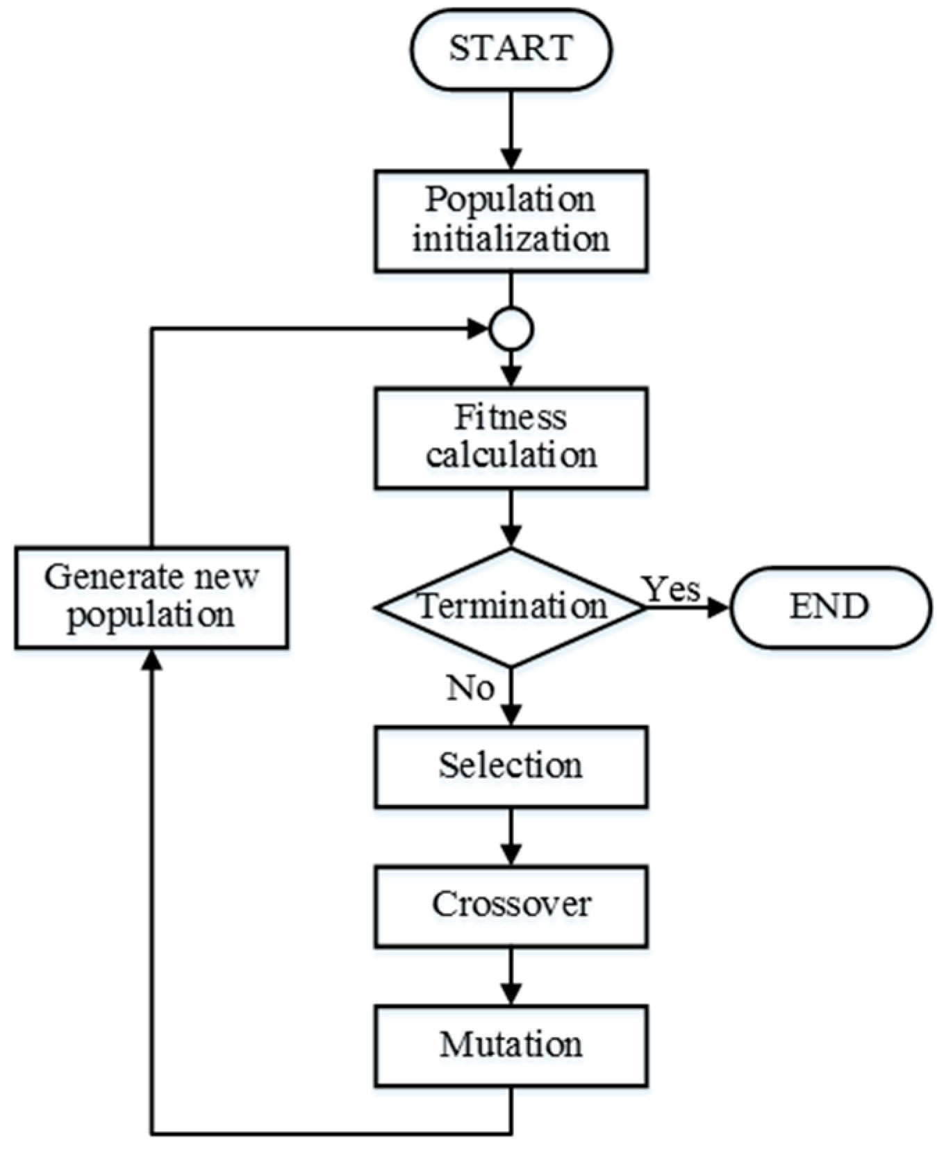
Figure 4 illustrates the fundamental procedure of GA. The evolution usually starts from a population of randomly generated individuals. In each generation, the fitness of every individual in the population is evaluated. The more fit individuals are stochastically selected from the current population, and each individual’s genome is modified by crossover and mutation operation to form a new generation. The new generation of candidate solutions is then used in the next iteration of the algorithm. When either a satisfactory fitness level has been reached, or a maximum number of generations have been produced, the algorithm terminates.
The above-mentioned GA is from a toolbox called Inspyred, which is a free, open source framework for creating biologically-inspired computational intelligence algorithms in Python. It is original, and no further development was done on it. In this optimization problem, there is only a single objective, total-to-static efficiency of turbines, so it is enough to briefly explore all of the design space.
Figure 5 shows the flowchart of the GA assisted radial inflow turbine preliminary design procedure. The GA drives the exploration of the design space defined by the loading coefficient, flow coefficient and rotational speed in a wide range. That is to say, the GA drives each new mean line design, and finally, when the convergence condition reaches requirements, the optimal result will be obtained.
In this paper, two preliminary designs are performed, the first one is a validation design without GA assistance that verifies the mean line design method by comparing the T-100 design parameters, and the second one is the T-100re designed using a GA assisted preliminary design procedure that aims to achieve the maximum efficiency under specified constraints. The GA will do the screening job automatically for better performance design without human intervention. The designer only needs to specify the constraint that should be satisfied in the design procedure.
3. Verification of Automated Preliminary Design Methodology
3.1. Mean Line Design
Table 1 shows the design parameters of the T-100 turbine [27]. Table 2 gives the ranges specified for loading coefficient, flow coefficient, and rotational speed. It can be seen that the specified range covers the most design area in Figure 2.
The results of the validation design for T-100 and T-100re optimization design are summarized in Table 3, and the T-100 original data is also listed as a comparison. The loading coefficient of the T-100 turbine is 0.91 [27], and the flow coefficient is selected as 0.22 by trial and error method to reach the main known parameters of the original T-100 turbine. It can be seen that the result is quite close to the T-100 original data, which verifies the correctness and accuracy of the present mean line design method.
The T-100re optimization is obtained using the present GA assisted preliminary design procedure. The GA configuration has a population size of 15, an elite number of 1, a mutation rate of 0.15 and a maximum generation number of 200. The convergence curve of the total-to-static efficiency is shown in Figure 6 and the T-100re turbine has a total-to-static efficiency of 87.4%. It can be found that the convergent speed is quite fast and the design process costs only a few minutes. Some key parameters like rotor inlet radius and blade number, etc. can be easily optimized through the empirical correlations in the preliminary design optimization, but hard to be optimized in the later three-dimensional (3D) numerical optimization, which indicates that it is strongly necessary to perform an optimization at the preliminary design stage.
For the T-100re turbine, the axial, radial and back face clearance is set to be 0.3, respectively, which is a minimum reasonable clearance. The six loss terms of the T-100re design are all lower than those of the verification design, which results in a higher total-to-static efficiency of 87.4%. The T-100re design has a smaller rotor inlet radius than that of the verification design, thus having a lower passage loss and nozzle loss. Though the rotor tip clearance of the T-100re design is a little bit larger than that of the verification design, the tip clearance loss is lower due to the smaller size too. Figure 7 shows a comparison of the meridional contours of these two turbines. It can be seen that the T-100re turbine has a lower inlet radius and shorter axial length of the rotor than the T-100 turbine. Therefore, the T-100re rotor weighs much lighter than the T-100, and the turbine‘s total weight will also reduce due to the lower radial geometry size of rotor, nozzle and the corresponding volute. It is of significance for APU of aerospace and turbine rotor of turbochargers.
Therefore, the present automated preliminary design approach is quite effective to determine the main parameters for the preliminary design. In this approach, the GA helps the designer find the best combination of () corresponding to the highest total-to-static efficiency under specified constraints and well-established loss models in a short time, thus making a good start for the later 3D numerical optimization work, which will be presented in Part II of this paper [34].
3.2. Numerical Computation
In 2012, Sauret [35] published a paper that intended to make the T-100 turbine an open benchmark for validation work and provided all the geometric data. In this study, an in-house blade design code for radial inflow turbines is developed in order to reconstruct the T-100 turbine based on the original data [27,35] and initialize the T-100re turbine design. Figure 8 and Figure 9 show the T-100 nozzle profile and the T-100 rotor geometry, respectively. The rotor blade is defined by the beta-angle and thickness distribution. An initial back face profile is provided for both T-100 and T-100re rotors so that the rotor weight can be evaluated. It turns out that the T-100 rotor weighs 1.31 kg and the T-100re rotor weighs 0.96 kg. Although the rotor weight is not an objective in the preliminary design optimization, the rotor weight could be decreased due to its smaller rotor size obtained by the preliminary design optimization.
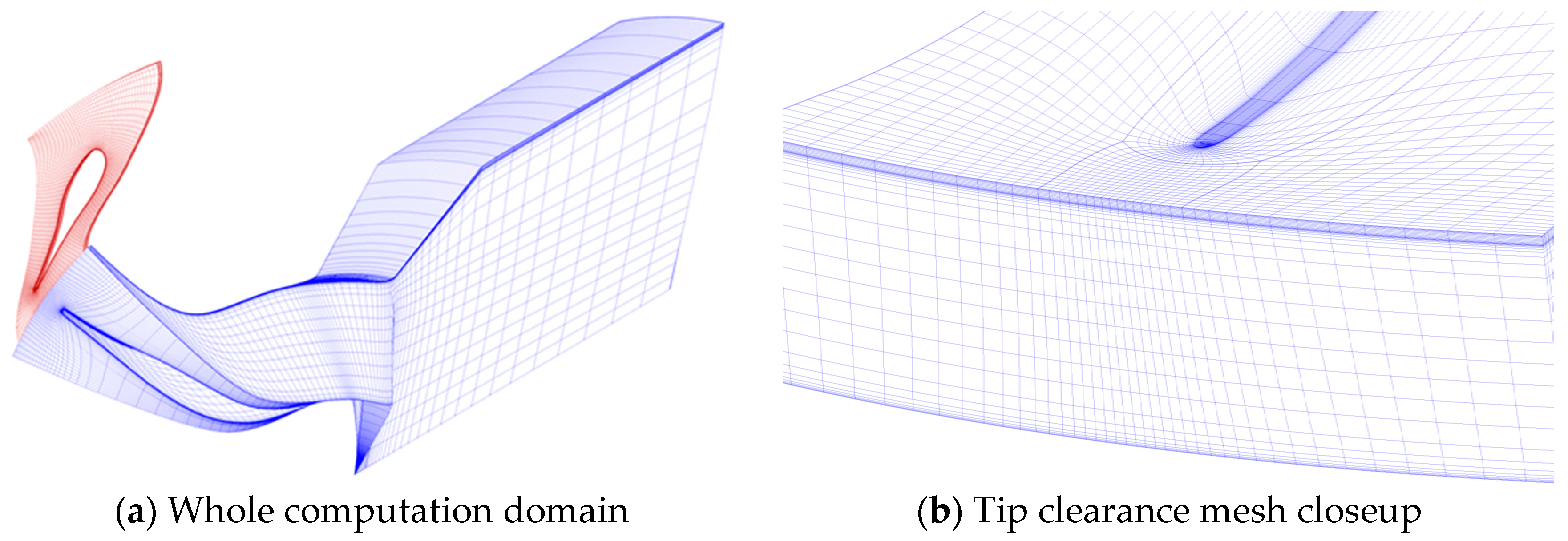
In order to validate the precision of the present preliminary design method, 3D numerical simulations are carried out for both T-100 and T-100re turbine under design and off-design conditions. Figure 10 shows the computational mesh of the T-100 turbine. A single passage of the nozzle and rotor flow path connected is considered as the computational domain. A long extension is provided in order to avoid the back-flow, and the rotor tip clearance is also considered. The T-100re turbine is meshed using the same configuration with T-100 turbine. The mesh statistics information is shown in Table 4. The simulations are conducted using ANSYS-CFX commercial CFD software (ANSYS, Inc., Canonsburg, PA, USA). The ideal air is selected as the working fluid. The RANS coupled with the SST turbulence model is solved with the first layer y+ less than 2. It is worth mentioning that the mesh number and the turbulence model used were verified by mesh independency and various turbulence models provided in ANSYS-CFX, respectively. The details of verification can be found in Reference [19] published by our research group.
The boundary conditions for validations are adopted using the design conditions in Table 1. It is noted that a modeling test was conducted with a T-100 turbine of a real geometry size (shown in Table 3), so the test boundary conditions are different from the design parameters. That is to say, the aerodynamic performance of T-100 turbine was tested under lower pressure and lower temperature at turbine inlet, and lower rotor rotational speed conditions (as shown in Table 5) according to similarity and modularization theory of turbomachinery.
Table 6 shows the total-to-static efficiency under design condition. It can be seen that the CFD results are just a little higher than those of the preliminary design and the T-100 preliminary result is in good agreement with the experimental data. It is worth mentioning that the mass flow rate of CFD is a little lower than the given preliminary value, about less than 1%. In order to compare, the mass flow rate of the modeling test was transferred to the design condition according to the similarity and modularization theory of turbomachinery. The result shows that the experimental mass flow rate is a bit bigger about 1% than the design value.
Figure 11 gives the comparison of total-to-static efficiency between the CFD and the experimental data under a range of velocity ratios, and it can be seen that the T-100 CFD results are a little higher than those of the experiment under each condition due to the ignorance of windage loss and flow non-uniformity at the volute outlet in the CFD simulations, but the changing trend of both results are in good agreement. It is worth mentioning that, through the mean line optimization, the optimal velocity ratio is 0.75 because the optimal rotation speed is higher than the original design speed.
It is to be noted that the experimental data of radial inflow turbines is scarce in public literature and there is only a few pieces of data that can be selected to verify the proposed approach. In Reference [27], no efficiency uncertainty is provided, and there is only the uncertainty of flow parameter mentioned, which was measured by an ASME standard inlet orifice, accurate to ±2%. In addition, the accuracy of power was checked through the compressor flow and temperature rise, and the power difference was generally within two percent of the power calculated from the turbine side. The reason shown in that paper was bearing and windage losses as well as measurement errors.
As a whole, the T-100re results are higher than those of the T-100 under most conditions, which demonstrates the effectiveness of the present automated preliminary design approach as well as the advantage of the T-100re turbine.
At the preliminary design stage, the T-100re turbine has a smaller inlet radius of 54.1 mm and a higher total-to-static efficiency of 87.4% as compared with the T-100 turbine, which means lighter weight and improved performance design is achieved. It can be seen that optimization conducted at the preliminary design stage is not only easy and low cost but also efficient. Some key parameters like blade number, rotor inlet diameter, and blade height, which are difficult to handle in 3D numerical optimization, can be easily treated in the mean line design optimization.
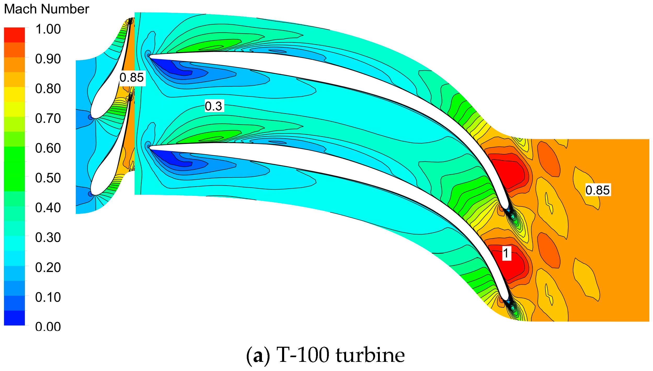
Figure 12 shows the comparison of Mach number contour between T-100 turbine and T-100re turbine at the mid-span section under design condition. At the outlet of the nozzle, the Mach number of T-100 turbine is lower than that of the T-100re turbine, while it is adverse at the outlet of the rotor. It is indicated that the enthalpy drop of T-100re turbine in the nozzle and the rotor is redistributed well, and the range of the lower Mach number in the rotor passage is reduced because of its higher rotational speed and reasonable rotor geometry. In addition, the absolute outlet velocity of T-100re turbine is 216.38 m/s, lower than that of T-100 turbine, 185.14m/s; thus, the total-to-static efficiency of the turbine is improved.
4. Conclusions
This paper presents an automated preliminary design approach for radial inflow turbines, as the first part of the integrated design and optimization approach. The GA is introduced to explore the design space defined by loading coefficients, flow coefficients, and rotational speeds. The aim of this design approach is to obtain the best design scheme with high aerodynamic performance under specified constraints and reduce the dependency on human experiences for designing a radial inflow turbine. The following conclusions can be drawn from this study.
(1) The mean line design method for radial inflow turbines is presented for getting the aerodynamic performance under given structure parameters. In addition, the radial inflow turbine T-100 published in the literature is used to verify this method. It is indicated that the verification result shows good agreement with the T-100 original data, which proves the correctness and accuracy of the present mean line design method.
(2) The automated preliminary method is developed by combining the mean line design with GA to explore the design space for obtaining the best design scheme of radial inflow turbines. The T-100 turbine is redesigned by using the automated preliminary method to check the effectiveness. It shows that the total-to-static efficiency of the T-100re turbine increases by 1.0% and the rotor weight decreases by 0.35 kg (26.7%) compared with the T-100 original design. Therefore this method can not only reduce the dependency on a designer’s expertise and guarantee the optimal design at the preliminary design stage under specified constraints but also make a good foundation for the later 3-D numerical optimization.
(3) The CFD results of T-100 and T-100re turbines are examined and compared to the T-100 turbine experimental data. It shows that the total-to-static efficiency is a little higher than that of the experiment results due to ignorance of the windage loss and the flow non-uniformity at the volute outlet in the CFD simulations, but the trend of both results are in good agreement. In addition, the performance of T-100re turbine is better than that of T-100 turbine under most conditions.
Author Contributions
Conceptualization, Q.D.; Methodology, Q.D. and S.S.; Software, L.F. and H.L.; Writing-Original Draft Preparation, S.S.; Writing-Review & Editing, Q.D. and Z.F.
Funding
This study is partially supported by the Specialized Research Fund for the Doctoral Program of Higher Education of China (Grant No. 20130201130005).
Conflicts of Interest
The authors declare no conflict of interest.
Abbreviations
| Notation | |
| blade height, m | |
| chord, m | |
| friction coefficient | |
| mass flow rate, kg/s | |
| rational speed of rotor, r/min | |
| radius, m | |
| average radius, m | |
| pitch, m | |
| blade thickness, m | |
| absolute flow velocity, m/s | |
| coefficient of axial and radial direction | |
| diameter of the hydraulic, m | |
| empirical coefficient | |
| length of the hydraulic, m | |
| number of rotor blades | |
| Reynolds number | |
| blade circular velocity, m/s | |
| relative flow velocity, m/s | |
| axial width of rotor, m | |
| absolute flow angle, ° | |
| relative flow angle, ° | |
| rotor tip clearance loss, kJ/kg | |
| rotor exit energy loss, kJ/kg | |
| incidence loss at rotor inlet, kJ/kg | |
| nozzle loss, kJ/kg | |
| rotor passage loss, kJ/kg | |
| trailing edge loss, kJ/kg | |
| windage loss, kJ/kg | |
| effective enthalpy drop of radial inflow turbines, kJ/kg | |
| total pressure loss of trailing edge, Pa | |
| clearance, m | |
| total-to-static efficiency | |
| density, kg/m3 | |
| average density, kg/m3 | |
| flow coefficient | |
| loading coefficient | |
| Subscripts | |
| a | axial direction |
| b | blade |
| h | hub location |
| m | meridional direction |
| opt | optimal value |
| r | radial direction |
| rms | root mean square value |
| s | shroud location |
| 1 | nozzle inlet, i.e., volute outlet |
| 2 | throat section of nozzle |
| 3 | exit section of nozzle |
| 4 | inlet section of rotor |
| 5 | throat section of rotor |
| 6 | exit section of rotor |
References
- Rohlik, H.E.; Kofskey, M.G.; Katsanis, T. Summary of NASA radial turbine research related to Brayton cycle space power system. Presented at the 2nd Interagency Energy Conversion Engineering Conference, Miami Beach, FL, USA, 13–17 August 1967. [Google Scholar]
- Bozza, F.; Bellis, V.D. Steady modeling of a turbocharger turbine for automotive engines. J. Eng. Gas Turbines Power 2014, 136, 011701. [Google Scholar] [CrossRef]
- Rodgers, C. The characteristics of radial turbines for small gas turbines. Presented at the ASME Turbo Expo 2003: Power for Land, Sea, and Air, Atlanta, GA, USA, 16–19 June 2003. [Google Scholar]
- Deng, Q.H.; Niu, J.F.; Mao, J.R.; Feng, Z.P. Experimental and numerical investigation on overall performance of a radial inflow turbine for 100 kW microturbine. Presented at the ASME Turbo Expo 2007: Power for Land, Sea, and Air, Montreal, QC, Canada, 14–17 May 2007. [Google Scholar]
- Rohlik, H.E. Analytical Determination of Radial Inflow Turbine Design Geometry for Maximum Efficiency; TN D-4384; NASA: Washington, DC, USA, 1968. [Google Scholar]
- Wasserbauer, C.A.; Glassman, A.J. FORTRAN Program for Predicting Off-Design Performance of Radial Inflow Gas Turbines; TN D-8063; NASA: Washington, DC, USA, 1975. [Google Scholar]
- Rodgers, C.; Geiser, R. Performance of a high efficiency radial/axial turbine. J. Turbomach. 1987, 109, 151–154. [Google Scholar] [CrossRef]
- Whitfield, A.; Baines, N.C. Chapter 3. In Design of Radial Turbomachines; Office of Scientific and Technical Information, U.S. Department of Energy: New York, NY, USA, 1990. [Google Scholar]
- Ye, F.; Feng, Z.P. Non-dimensional preliminary design and optimization for radial inflow turbine. Gas Turbine Technol. 1998, 11, 28–31. [Google Scholar]
- Ebaid, M.S.Y.; Bhinder, F.S.; Khdairi, G.H. A unified approach for designing a radial flow gas turbine. J. Turbomach. 2003, 125, 598–606. [Google Scholar] [CrossRef]
- Mistry, C.S.; Channiwala, S.A. Design of nozzle-less radial inflow gas turbine for small capacity (20kW) gas turbine engine. Presented at the ASME 2004 International Mechanical Engineering Congress and Exposition, Anaheim, CA, USA, 13–19 November 2004. [Google Scholar]
- Feng, Z.P.; Deng, Q.H.; Li, J. Aerodynamic design and numerical simulation of radial inflow turbine impeller for a 100kW microturbine. Presented at the ASME Turbo Expo 2005: Power for Land, Sea, and Air, Reno, NV, USA, 6–9 June 2005. [Google Scholar]
- Deng, Q.H. Design and Development, Aerodynamic Performance Test, and Tip Clearance Flow Characteristics of a Radial Inflow Turbine for 100 kW Microturbines. Ph.D. Thesis, Xi’an Jiaotong University, Xi’an, China, December 2008. [Google Scholar]
- Suhrmann, J.F.; Peitsch, D.; Gugau, M.; Heuer, T.; Tomm, U. Validation and development of loss models for small size radial turbines. Presented at the ASME Turbo Expo 2010: Power for Land, Sea, and Air, Glasgow, UK, 14–18 June 2010. [Google Scholar]
- Ghosh, S.K.; Sahoo, R.K.; Sarangi, S.K. Mathematical analysis for off-design performance of cryogenic turboexpander. J. Fluids Eng. 2011, 133, 031001. [Google Scholar] [CrossRef]
- Fu, L.; Shi, Y.; Deng, Q.H.; Li, H.Z.; Feng, Z.P. Integrated optimization design for a radial turbine wheel of a 100 kW-class microturbine. J. Eng. Gas Turbines Power 2011, 134, 012301. [Google Scholar] [CrossRef]
- Fu, L. Comprehensive Design Method, Internal Flow Characteristics and Experimental Investigation of Micro Radial Turbine with Millimeter-scale. Ph.D. Thesis, Xi’an Jiaotong University, Xi’an, China, September 2011. [Google Scholar]
- Ventura, C.A.M.; Jacobs, P.A.; Rowlands, A.S.; Prtrie-Repar, P.; Sauret, E. Preliminary design and performance estimation of radial inflow turbine: An automated approach. J. Fluids Eng. 2012, 134, 031102. [Google Scholar] [CrossRef]
- Shao, S. Multidisciplinary Integrated Design and Optimization Method for Radial Inflow Turbine. Ph.D. Thesis, Xi’an Jiaotong University, Xi’an, China, July 2015. [Google Scholar]
- Al-Jubri, A.M.; Al-Dadah, R.; Mahmoud, S. New performance maps for selecting suitable small-scale turbine configuration for low-power organic Rankine cycle applications. J. Clean. Prod. 2017, 161, 931–946. [Google Scholar] [CrossRef]
- Al-Jubri, A.M.; Al-Dadah, R.; Mahmoud, S.; Daabo, A. Modelling and parametric analysis of small-scale axial and radial-outflow turbines for organic Rankine Cycle applications. Appl. Energy 2017, 190, 981–996. [Google Scholar] [CrossRef]
- Lio, L.D.; Manente, G.; Lazzaretto, A. A mean-line model to predict the design efficiency of radial inflow turbines in organic Rankine cycle systems. Appl. Energy 2017, 205, 187–209. [Google Scholar] [CrossRef]
- Mounier, V.; Olmedo, L.E.; Schiffmann, J. Small scale radial inflow turbine performance and pre-design maps for organic Rankine cycle. Energy 2018, 143, 1072–1084. [Google Scholar] [CrossRef]
- Lv, G.C.; Yang, J.G.; Shao, W.Y.; Wang, X.F. Aerodynamic design optimization of radial-inflow turbine in super CO2 cycles using a one-dimensional model. Energy Convers. Manag. 2018, 165, 827–839. [Google Scholar] [CrossRef]
- Zhou, A.Z.; Song, J.; Li, X.S.; Ren, X.D.; Gu, C.W. Aerodynamic design and numerical analysis of a radial inflow turbine for the supercritical carbon dioxide Brayton cycle. Appl. Therm. Eng. 2018, 132, 245–255. [Google Scholar] [CrossRef]
- Moustapha, H.; Zelesky, M.F.; Baines, N.C.; Japikse, D. Chapter 7–10. In Axial and Radial Turbines; Concepts ETI, Inc.: Plano, TX, USA, 2003. [Google Scholar]
- Jones, A.C. Design and test of a small, high pressure ratio radial turbine. J. Turbomach. 1996, 118, 362–370. [Google Scholar] [CrossRef]
- Chen, H.; Baines, N.C. The aerodynamic loading of radial mixed-flow turbines. Int. J. Mech. Sci. 1994, 36, 63–79. [Google Scholar] [CrossRef]
- Dambach, R.; Huntsman, I.; Hodson, H.P. An experimental study of tip clearance flow in radial inflow turbine. J. Turbomach. 1999, 121, 644–650. [Google Scholar] [CrossRef]
- Glassman, A.J. Enhanced Analysis and User’s Manual for Radial Inflow Turbine Conceptual Design Code RTD; NASA-CR-195454, E-9538, NAS 1.26:195454; NASA: Washington, DC, USA, 1995. [Google Scholar]
- Daily, J.W.; Nece, R.E. Chamber dimension effects on induced flow and frictional resistance of enclosed rotating disks. J. Basic Eng. 1960, 82, 217–230. [Google Scholar] [CrossRef]
- Marscher, W.D. Structural analysis: Stresses due to centrifugal, pressure and thermal loads in radial turbines. In Radial Turbines; The Von Karman Institute for Fluid Dynamics: St. Heines-Rod, Belgium, 1992. [Google Scholar]
- Trigg, M.A.; Tubby, G.R.; Sheard, A.G. Automatic genetic optimization approach to two-dimensional blade profile design for steam turbines. J. Turbomach. 1999, 121, 11–17. [Google Scholar] [CrossRef]
- Deng, Q.H.; Shao, S.; Fu, L.; Luan, H.F.; Feng, Z.P. An integrated design and optimization approach for radial inflow turbines-part II: Multidisciplinary optimization design. Appl. Sci. 2018, 8, 2030. [Google Scholar] [CrossRef]
- Sauret, E. Open design of high pressure ratio radial inflow turbine for academic validation. Presented at the ASME 2012 International Mechanical Engineering Congress and Exposition, Houston, TX, USA, 9–15 November 2012. [Google Scholar]
Figure 1.
Components of a radial inflow turbine.


Figure 3.
Flowchart of the mean line design process.

Figure 4.
Genetic algorithm (GA) procedure.

Figure 5.
Flowchart of GA assisted preliminary design procedure.

Figure 6.
Convergence curve of the optimal design.

Figure 7.
Comparison of meridional contour.

Figure 8.
T-100 nozzle profiles.

Figure 9.
T-100 rotor geometry.

Figure 10.
Computational mesh of the T-100.

Figure 11.
Comparison of total-to-static efficiency.

Figure 12.
Comparison of Mach number contour at the mid-span section.


Table 1.
Design parameters of T-100 turbine.
| Items | Unit | Value |
|---|---|---|
| Fluid | [-] | Air |
| Rotational Speed | [r/min] | 106,588 |
| Inlet Total Temperature | [K] | 1056.5 |
| Inlet Total Pressure | [kPa] | 580.4 |
| Mass Flow Rate | [kg/s] | 0.33 |
| Number of Nozzle Vanes | [-] | 19 |
| Number of Rotor Blades | [-] | 16 |
| Pressure Ratio | [-] | 5.73 |
| Power | [kW] | 121 |
Table 2.
Range of design space.
| Loading Coefficient [-] | Flow Coefficient [-] | Rotational Speed [r/min] | |
|---|---|---|---|
| Range | 0.7–1.1 | 0.1–0.4 | 10,000–130,000 |
Table 3.
Results of the validation design and optimization design.
| Parameters | Unit | T-100 (Original) | Verification | T-100re (Optimization) |
|---|---|---|---|---|
| Loading Coefficient | [-] | 0.91 | 0.91 | 0.90 |
| Flow Coefficient | [-] | - | 0.22 | 0.21 |
| Rotational Speed | [r/min] | 106,588 | 106,588 | 114,185 |
| Rotor | ||||
| Inlet Radius | [mm] | 58.2 | 57.3 | 54.1 |
| Inlet Blade Height | [mm] | 6.35 | 6.35 | 6.84 |
| Inlet absolute Flow Angle | [°] | 76.8 | 76.6 | 77.0 |
| Inlet relative Flow Angle | [°] | −31.8 | −22.5 | −27.0 |
| Axial Clearance | [mm] | 0.25 | 0.25 | 0.3 |
| Radial Clearance | [mm] | 0.22 | 0.22 | 0.3 |
| Backface Clearance | [mm] | 0.46 | 0.46 | 0.3 |
| Number of Rotor Blades | [-] | 16 | 16 | 14 |
| Outlet Hub Radius | [mm] | 15.2 | 15.2 | 14.2 |
| Outlet Shroud Radius | [mm] | 36.8 | 36.3 | 37.5 |
| Outlet Blade Height | [mm] | 21.6 | 21.1 | 23.4 |
| Outlet Absolute Flow Angle | [°] | −0.03 | 0 | 0 |
| Outlet Relative Flow Angle | [°] | −57.4 | −64.2 | −66.7 |
| Chord Length | [mm] | 45.7 | 40.9 | 40.5 |
| Trailing Edge Thickness | [mm] | 0.76 | 0.50 | 0.43 |
| Nozzle | ||||
| Inlet Radius | [mm] | 74.0 | 74.0 | 69.0 |
| Blade Height | [mm] | 6.35 | 6.35 | 6.84 |
| Outlet Radius | [mm] | 63.5 | 63.5 | 59.1 |
| Outlet Absolute Flow Angle | [°] | 77.8 | 77.8 | 77.0 |
| Chord Length | [mm] | 22.9 | 22.9 | 20.0 |
| Trailing Edge Thickness | [mm] | 0.51 | 0.51 | 0.36 |
| Number of Nozzle Vanes | [-] | 19 | 19 | 17 |
| Nozzle Loss | [kJ/kg], [%] | - | 11.63, 19.88 | 10.81, 19.64 |
| Incidence Loss | [kJ/kg], [%] | - | 0.19, 0.33 | 0.03, 0.06 |
| Passage Loss | [kJ/kg], [%] | - | 26.06, 44.55 | 25.66, 46.62 |
| Tip Clearance Leakage Loss | [kJ/kg], [%] | - | 8.88, 15.18 | 7.67, 13.93 |
| Exit Energy Loss | [kJ/kg], [%] | - | 9.64, 16.48 | 8.89, 16.15 |
| Windage Loss | [kJ/kg], [%] | - | 2.09, 3.58 | 1.98, 3.60 |
| Total-to-static Efficiency | [%] | 86.4 | 86.4 | 87.4 |
Table 4.
Mesh statistic information.
| Cases | Nozzle | Rotor | Diffuser |
|---|---|---|---|
| T-100 | 156,925 | 289,363 | 629,520 |
| Optimal | 156,925 | 289,363 | 517,200 |
Table 5.
Design condition of the test rig.
| Items | Unit | Value |
|---|---|---|
| Inlet total temperature | [K] | 477.59 |
| Inlet total pressure | [kPa] | 405.26 |
| Outlet static pressure | [kPa] | 70.73 |
| Rotational speed | [r/min] | 71,665 |
Table 6.
Comparison of total-to-static efficiency and mass flow rate under the design condition.
| Assessment Methods | Efficiency [%] | Mass Flow Rate [kg/s] | ||
|---|---|---|---|---|
| T-100 | T-100re | T-100 | T-100re | |
| Preliminary | 86.4 | 87.4 | 0.33 | 0.33 |
| Experiment | 86.4 | - | 0.333 * | - |
| Computational Flow Dynamics (CFD) | 87.4 | 88.3 | 0.328 | 0.327 |
*: It is calculated out to the design condition according to the measured mass flow rate of the modeling test.
© 2018 by the authors. Licensee MDPI, Basel, Switzerland. This article is an open access article distributed under the terms and conditions of the Creative Commons Attribution (CC BY) license (http://creativecommons.org/licenses/by/4.0/).
Share and Cite
MDPI and ACS Style
Deng, Q.; Shao, S.; Fu, L.; Luan, H.; Feng, Z. An Integrated Design and Optimization Approach for Radial Inflow Turbines—Part I: Automated Preliminary Design. Appl. Sci. 2018, 8, 2038. https://doi.org/10.3390/app8112038
AMA Style
Deng Q, Shao S, Fu L, Luan H, Feng Z. An Integrated Design and Optimization Approach for Radial Inflow Turbines—Part I: Automated Preliminary Design. Applied Sciences. 2018; 8(11):2038. https://doi.org/10.3390/app8112038
Chicago/Turabian StyleDeng, Qinghua, Shuai Shao, Lei Fu, Haifeng Luan, and Zhenping Feng. 2018. "An Integrated Design and Optimization Approach for Radial Inflow Turbines—Part I: Automated Preliminary Design" Applied Sciences 8, no. 11: 2038. https://doi.org/10.3390/app8112038
Note that from the first issue of 2016, this journal uses article numbers instead of page numbers. See further details here.