1. Introduction
Long-stroke and nanopositioning planar stages with nanometer-scale resolution and accuracy are essential in various precision systems, such as electronic device manufacturing equipment and scanning-type measuring instruments [
1,
2]. Stacked-type planar stages are conventionally constructed with two linear stages by stacking one on top of the other [
3,
4]. However, the stacked-type planar stages suffer from Abbe error, because the reference axis cannot be in line with the functional axis in the working space; thus, the stacked-type planar stages are not proper from the viewpoints of both positioning accuracy and positioning speed. Gantry stages [
5], consisting of two
x-axes and a
y-axis, provide high capacity and high stiffness. Their travel accuracy, however, is significantly influenced by the parallelism of two
x-axes and the Abbe error is also large due to the large Abbe offset.
Compared with the stacked-type planar stage and the gantry stage, coplanar stages can eliminate the Abbe error by allowing the
x- and
y-motions along a common plane [
6,
7,
8,
9]. The coplanar stage needs to be equipped with a high-precision position sensor for closed-loop control of each axis’ motion. Linear encoders are regarded as more stable than laser interferometers for ultra-precision displacement measurement, as the mechanical grid is less sensitive to the ambient condition than the laser wavelength [
10]. However, due to the geometric design of linear encoders, it is difficult to follow the Abbe principle when being installed into the coplanar stage as the feedback sensor. Commercial laser interferometers, made of He–Ne lasers featuring a long measurement range, fast speed, and nanometric resolution, are widely used for the calibration tool of linear stages. However, their sizes are too bulky to be embedded into the small nanopositioning stage as a feedback sensor. A linear displacement grating interferometer (LDGI), which employs the polarization technique to obtain low-noised sinusoidal waveforms, was developed to detect the
x- and
y-motions [
6,
7]. However, the stage motion has inevitable geometrical angular errors that would cause pulse counting errors of the LDGI. A novel miniature laser diode interferometer based on the Michelson interferometer principle was, thus, developed for precision displacement feedback in each axis of a nanopositioning stage by the authors’ group [
11]. However, although the laser diode has the advantage of small size, it suffers from low stability in output power and wavelength, which is the length unit of laser interferometer, thereby limiting its applications in length measurements. In addition, the novel miniature laser diode interferometer cannot measure angular errors of the moving stage. It is known that angular errors induce Abbe errors in displacement measurements, which influence the displacement feedback accuracy of the laser diode interferometer. In order to achieve a high-precision closed-loop displacement feedback control of the nanopositioning stage, it is essential to ensure the accuracy of the laser diode wavelength and compensate for the angular-error-induced Abbe error.
There are many methods for correcting the laser wavelength in room conditions. An air sensor, which is used to detect the current temperature, relative humidity, and atmospheric pressure to correct the refractive index of air through an empirical equation with a reference wavelength in vacuum, is commonly required in commercial laser interferometers. The empirical equation is usually taken from the Edlen equation [
12] or its modified equations [
13,
14]. However, on the one hand, the empirical equation was obtained based on the He–Ne laser, which has different properties from the laser diode. On the other hand, the empirical method is an indirect measurement, which is subject to the sensitivity and accuracy of the air sensor. Therefore, the correction of laser diode wavelength cannot directly adopt existing empirical equations.
Compared with the indirect measurement method, the direct measurement method can obtain real-time laser wavelength. An interferometer comparator can be used for laser wavelength measurements by analyzing the relationship between the phase [
15,
16] or the period [
17,
18] of interference fringes and the laser wavelength. The interference fringes are obtained when an optical path difference between a reference path and a measurement path is generated in the interferometer. The common measurement systems are Michelson interferometers [
19,
20] and Mach–Zehnder interferometers [
21] with mirrors or cube corners. However, in the interferometer comparator, a reference laser is necessary, and the measurement accuracy depends significantly on the laser coherence. Optical beating methods with a certain optical path different can be employed to make a highly accurate measurement of the laser wavelength [
22,
23]. Optical beating methods are based on frequency comparisons with a laser stabilized by means of the saturated absorption method [
22] or with a comb-generator [
23]. Wavelength can also be measured based on specific wavelength-dependent material properties, such as specialties of optical fiber [
24], polarization of light [
25], and diffraction gratings [
16,
26]. The nature of simple structure and portability of this kind of wavelength measurement method predestinates it to be applied in different kinds of commercial systems, especially gratings, in which laser wavelength can be calculated by detecting the variation of diffraction angle with a charge-coupled device (CCD) [
16]. However, CCD cannot provide high-precision wavelength measurements due to its low resolution and accuracy.
In this study, a laser-diode-based miniature Michelson interferometer (MMI) with self-wavelength correction based on the grating diffraction principle and the autocollimation principle is proposed. Combining the MMI with a dual-angle sensor based on the autocollimation principle, a compact three-degree-of-freedom laser measurement (3DOFLM) system is developed, which is employed as the displacement feedback sensor, as well as pitch and yaw angular sensors, of a nanopositioning stage. The optical layout of the 3DOFLM system is designed in such a way that the displacement and two angular motions of the nanopositioning stage can be detected simultaneously. The laser wavelength can be corrected in real time during the displacement feedback. A prototype system was constructed. The principle of the 3DOFLM system design and its performance tests are presented in the following sections.
2. Principle of the Miniature Michelson Interferometer (MMI)
Figure 1a shows the configuration of a nanopositioning
y-stage. The linear bearing between the linear slide and the moving table is to allow the installation of another
x-stage to form a coplanar stage. For the sake of clarity, only the displacement feedback control along the
y-direction is plotted. The ultrasonic motor is employed to actuate the linear slide through a friction force on the ceramic plate. Thus, the moving table can be moved by the linear slide in push–pull mode. The three-degree-of-freedom laser measurement (3DOFLM) system, consisting of a miniature Michelson interferometer (MMI) kit for displacement measurement and feedback, a wavelength correction kit for the MMI kit, and a miniature autocollimator kit for angular error measurement, is mounted onto the baseplate of the stage and on the opposite side of the ultrasonic motor. The laser beam of the 3DOFLM system is in line with the moving axis at the center of the stage. With this kind of arrangement, the Abbe principle is totally observed. The optical design of the 3DOFLM system is shown in
Figure 1b. A low-cost laser diode is employed as the laser source. The miniature autocollimator kit is employed to detect the pitch and yaw angular errors for the purpose of Abbe error compensation of the stage. The displacement of the stage detected by the MMI kit is used as a feedback signal to the ultrasonic motor. The laser diode wavelength of the MMI kit is corrected in real time by the wavelength corrector kit. The detailed principles of angular error measurement and displacement measurement with and without wavelength correction are introduced below.
2.1. Angular Error Measurement of the Nanopositioning Stage
The principle of angular error measurement is based on the autocollimation principle. A collimated laser beam emitted from a laser diode is divided into a transmitted measurement beam (P-polarized beam) and a reflected reference beam (S-polarized beam) by a polarizing beam splitter (PBS1), as shown in
Figure 1. The measurement beam reflected by a moving mirror (mirror 3) is split into two beams by a beam splitter (BS2). The reflected beam is used to measure pitch and yaw errors of the nanopositioning stage by an autocollimator (AC1), comprising a focus lens (FL1) and a four-quadrant photodetector (QPD1).
Figure 2 shows the optical layout of the miniature autocollimator kit. BS2 is mounted on an angle mirror mount for easy angle adjustment. QPD1 is positioned on the focal point of FL1. When mirror 3 is rotated with a pitch angle or a yaw angle, the position of the focused spot on QPD1 is moved along the
x- or
y-directions, accordingly. The relationship between the angle and laser spot movement can be expressed by the following equations:
where
θpitch and
θyaw are the pitch and yaw errors, Δ
x and Δ
y are the corresponding spot shifts on QPD1, and
f is the focal length of FL1.
2.2. Displacement Measurement of the Nanopositioning Stage
Due to the space limit of the nanopositioning stage, a miniature Michelson interferometer (MMI) kit is developed for displacement feedback, as shown in
Figure 3a. A collimated laser beam emitted from a laser diode is divided into a measurement beam and a reference beam by PBS1, as shown in
Figure 1. The reference beam passes through a quarter waveplate (QWP2) and is reflected back by a fixed mirror (mirror 2). The measurement beam passes through QWP1 and is reflected back by the moving mirror (mirror 3). It should be noted that the polarization state of the measurement and reference beams are changed by 90° after passing QWP2 and QWP1 twice, which prevents the reflected beams from entering back into the laser diode. Those two reflected beams are combined at PBS1 and converted into left and right circularly polarized beams after passing through QWP3. The interference signals with a phase shift of 90° due to the phase control by two PBSs (PBS2 and PBS3) and a BS (BS3) are detected by four photodetectors (PD1–PD4), as shown in
Figure 3b. The motion of the moving mirror 3 causes an optical path difference between the two reflected beams so as to produce interference. Analyzed by the Jones matrix, the intensity of each photodetector can be expressed as follows:
where
I0 and
λ are the intensity and the wavelength of the laser beam, respectively, and Δ
y is the optical path difference of two reflected beams. The signal direct current (DC) offset can be eliminated by subtracting Equation (2) from Equation (3) for the cosine term, and Equation (5) from Equation (4) for the sine term. The phase change can be obtained by
Based on the optical design of the MMI kit, when mirror 3 has a motion of
d, the optical path difference of the two reflected beams Δ
z will be 2
d. Thus, the displacement
d of the moving mirror 3 can be calculated by
where
N is the number of sinusoidal waves, and Φ
initial and Φ
final are the exact phases of initial and final incomplete wave cycles, respectively. It can be seen from Equation (7) that the interference waveform has the period of one-half laser wavelength. Thus, the accuracy of the laser wavelength is significantly important in the MMI kit.
2.3. Correction of Laser Diode Wavelength in the MMI Kit
The wavelength corrector kit is based on the grating diffraction principle and the autocollimation principle, as shown in
Figure 4. The divided reference beam is transmitted through BS1 and impinged into a grating. A group of diffraction beams can be observed. Here, the zeroth (0th) order and positive first (+1st) order diffraction beams are picked up for calculating laser wavelength. Based on the diffraction grating equation, the following equation can be obtained:
where
d is the grating pitch,
θi is the incidence angle,
λn is the nominal laser wavelength, and
θd is the +1st order diffraction angle with respect to
λn. As seen from Equation (8), the wavelength can be calculated if the +1st order diffraction angle can be measured at known incidence angle and grating pitch. This is also the measurement principle of typical spectrometers [
26]. In the designed wavelength corrector, the laser beam is set to normally project onto the grating; thus, the incidence angle is 0. However, if the nominal wavelength is varied by Δ
λ, the diffraction angle will have a drift. Thus, Equation (8) can be modified to
where Δ
θd is the drift of +1st order diffraction angle due to Δ
λ.
From Equation (9), it is seen that, if Δθd can be measured in real time, Δλ can be immediately calculated, and the real-time laser wavelength can then be automatically self-corrected without the need of the air sensor and the Edlen equation. This is the significance of the proposed self-wavelength correction.
3. Experiments and Discussions
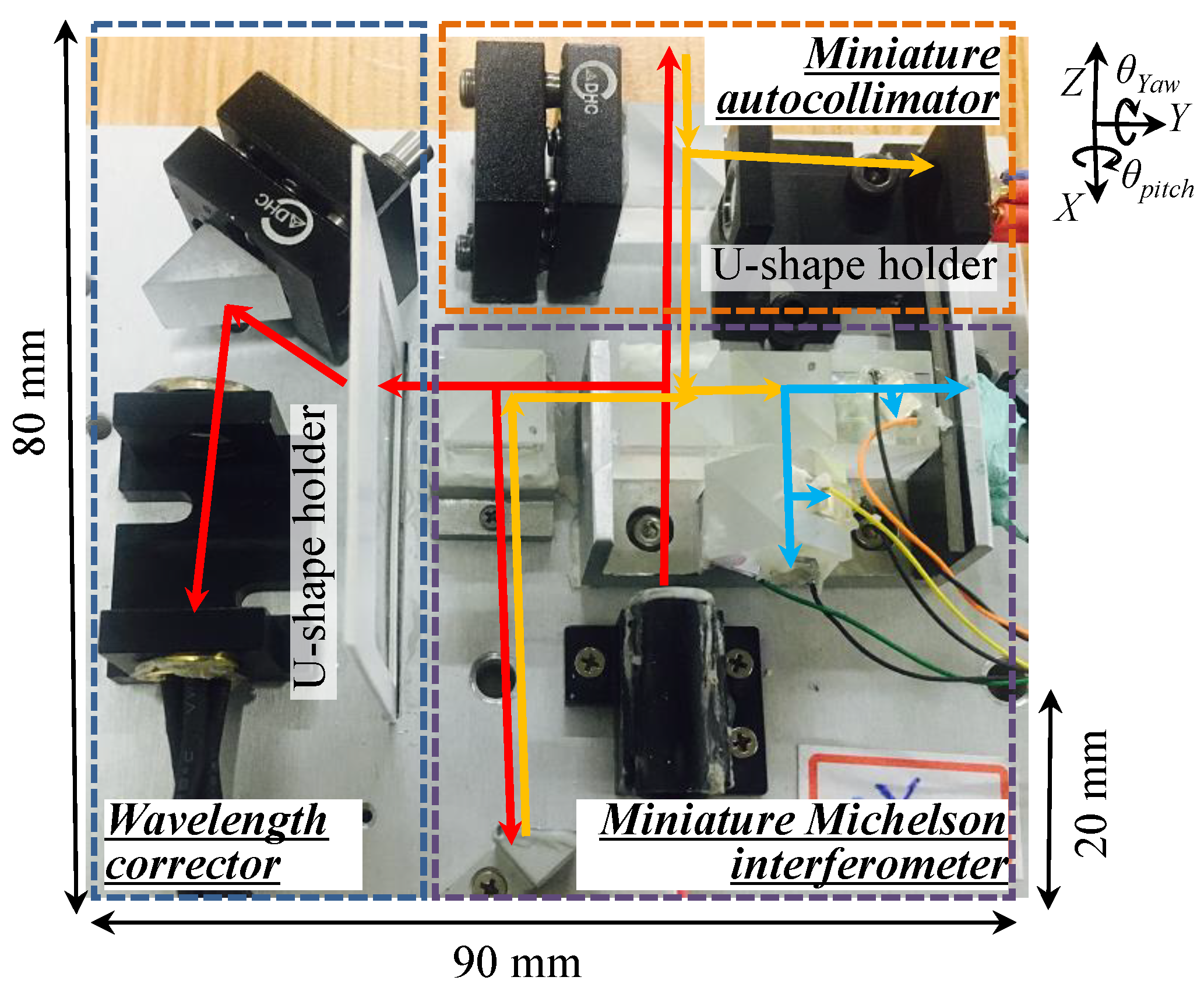
Figure 5 shows a photo of the constructed 3DOFLM system. Its size, including the electric cables and the base plate for mounting the optical components, is 80 mm (
x) × 90 mm (
y) × 20 mm (
z), which is much smaller than commercial He–Ne laser interferometers. The U-shaped holder was made to fix both FL and QPD in one place for better assembly accuracy. It should be noted that, due to the space limit of the nanopositioning stage, the dead path of the 3DOFLM system, which is the distance between the MMI kit and the null point of the measurement position, was designed to be 36 mm. Therefore, the error due to the dead path is negligible [
27].
In order to achieve accurate displacement of the nanopositioning stage, it is essential to investigate the performance of the designed 3DOFLM system. It should be noted that all experiments were carried out in a non-environmental controlled open laboratory in which disturbances caused by temperature change and humidity variation cannot be avoided.
3.1. Calibration and Comparison Experiments of Angular Error Measurement
Firstly, the basic performances of the miniature autocollimator kit, including stability and measurement accuracy, were tested. A commercial low-cost collimated laser diode with a nominal wavelength of 635 nm and a divergence angle less than 0.3 mrad was adopted as the laser source. A high-precision QPD (SPOT-4DMI, OSI Optoelectronics, California, USA) with an active area of 0.25 mm per element, an element gap of 13 μm, and a responsivity of 0.65 A/W was chosen as the angle detector. The sampling frequency was set to be 10 Hz, and a Butterworth filter was used to reduce the noise level.
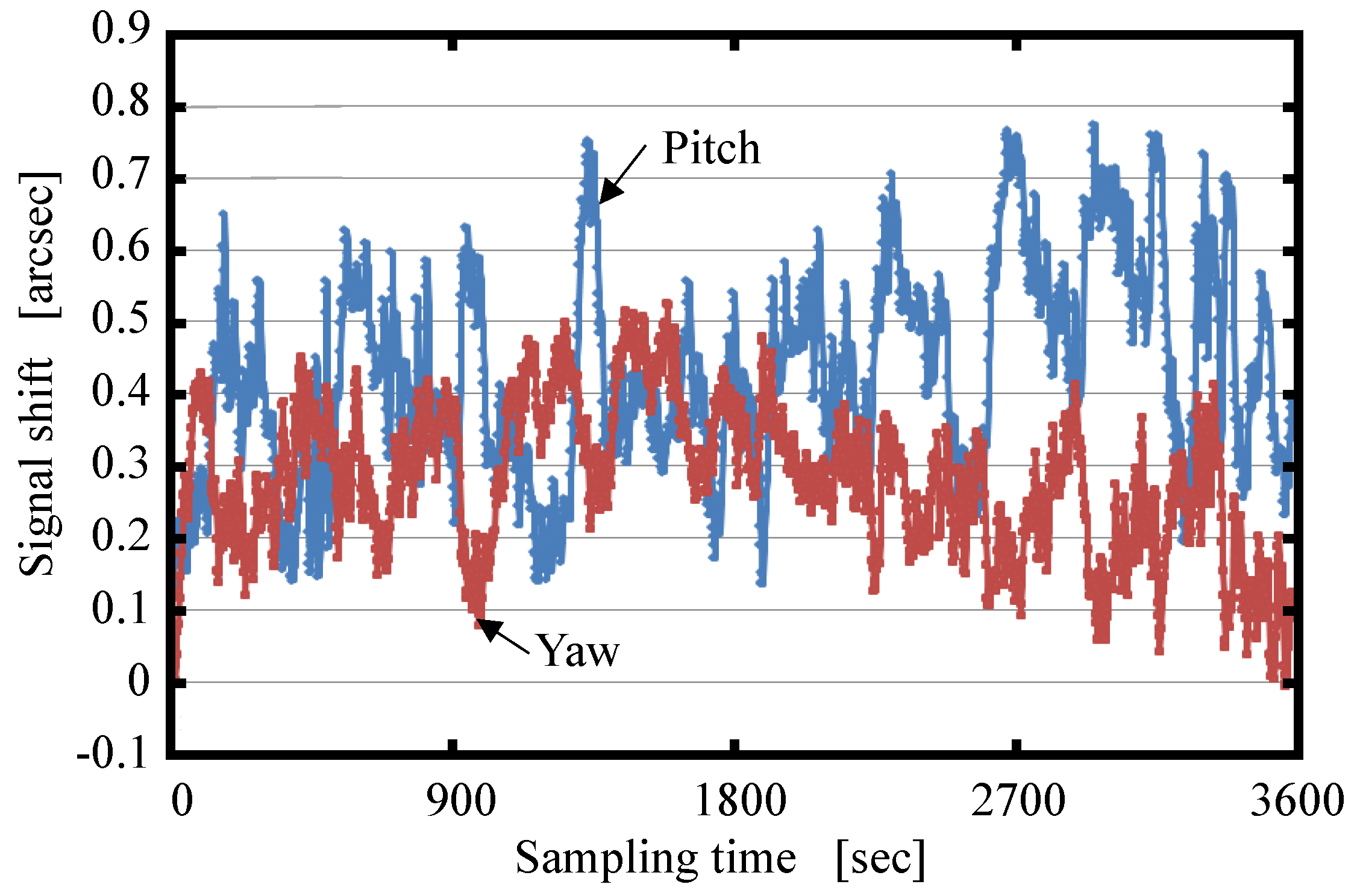
Figure 6 shows the stability of the angular errors over a duration of 1 h. As seen, the stability of the output signals for measuring the pitch angle error and yaw angle error were approximately 0.55 and 0.35 arcsec, respectively. It should be noted that, although the laser beams for measuring the pitch and yaw angle errors were from an identical laser diode, due to the non-uniformity of the output intensity distribution of the laser diode, the stability in pitch and yaw angle error measurements were not similar, but inversely correlated in
Figure 6. The reason for the larger pitch variation could be due to the mechanical vibration. It can be seen that the developed miniature autocollimator kit satisfied stability for angular error measurements with sub-arcsecond precision.
Prior to the testing the nanopositioning stage’s angular error, the miniature autocollimator kit was calibrated by a commercial laser interferometer (HP5529A, Keysight Technologies, California, USA), which has an angle measurement accuracy of ±0.2% of displayed value and ±0.05 arcsec per meter of distance traveled. The experiments were repeated five times, and the calibration range was set to be ±40 arcsec. The comparative results are shown in
Figure 7a,b. It can be seen that the residuals of pitch angle and yaw angle were all within ±0.3 arcsec.
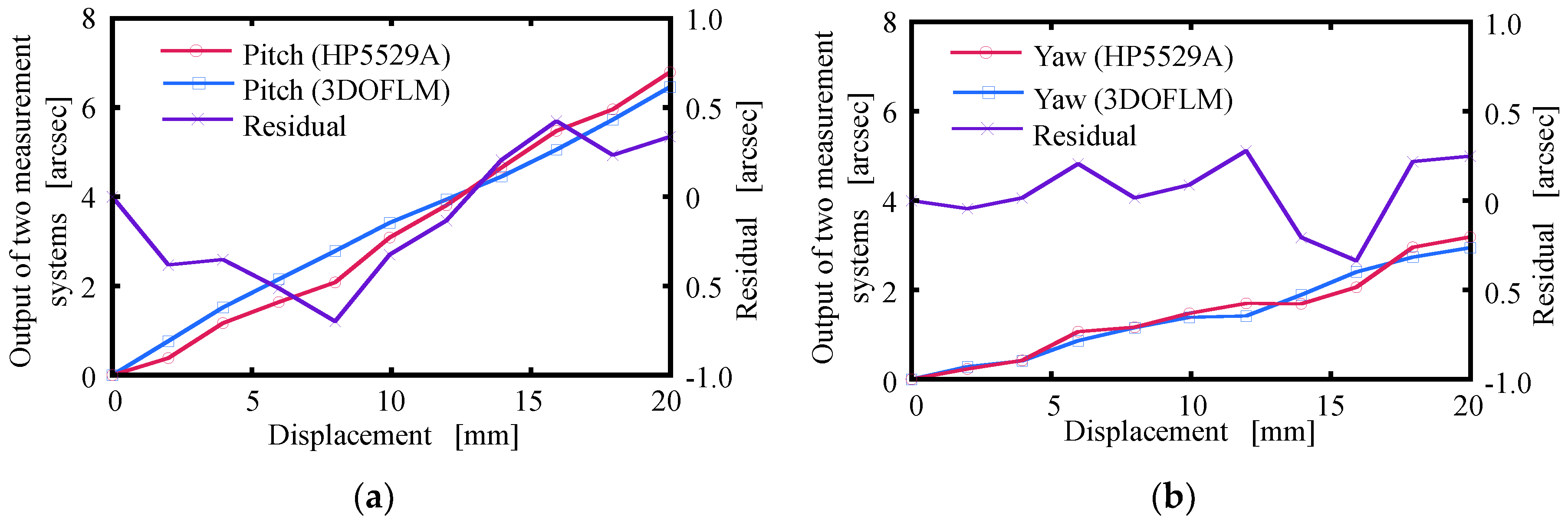
The 3DOFLM system was then mounted on the designed nanopositioning stage [
6] to measure the angular error of the stage. The HP5529A interferometer was also adopted for comparison. The laser beams of both the 3DOFLM and HP5529A systems were adjusted in line with the motion axis of the stage.
Figure 8a,b show the measurement results. It is seen that the output of the 3DOFLM system was in a good agreement with that of the HP5529A system. The maximum residual of both angles was within ±0.5 arcsec in the measurement distance of 20 mm. It is verified that the performance of the designed 3DOFLM system was acceptable for sub-arcsecond precision angular error measurement.
3.2. Displacement Measurement without Wavelength Correction
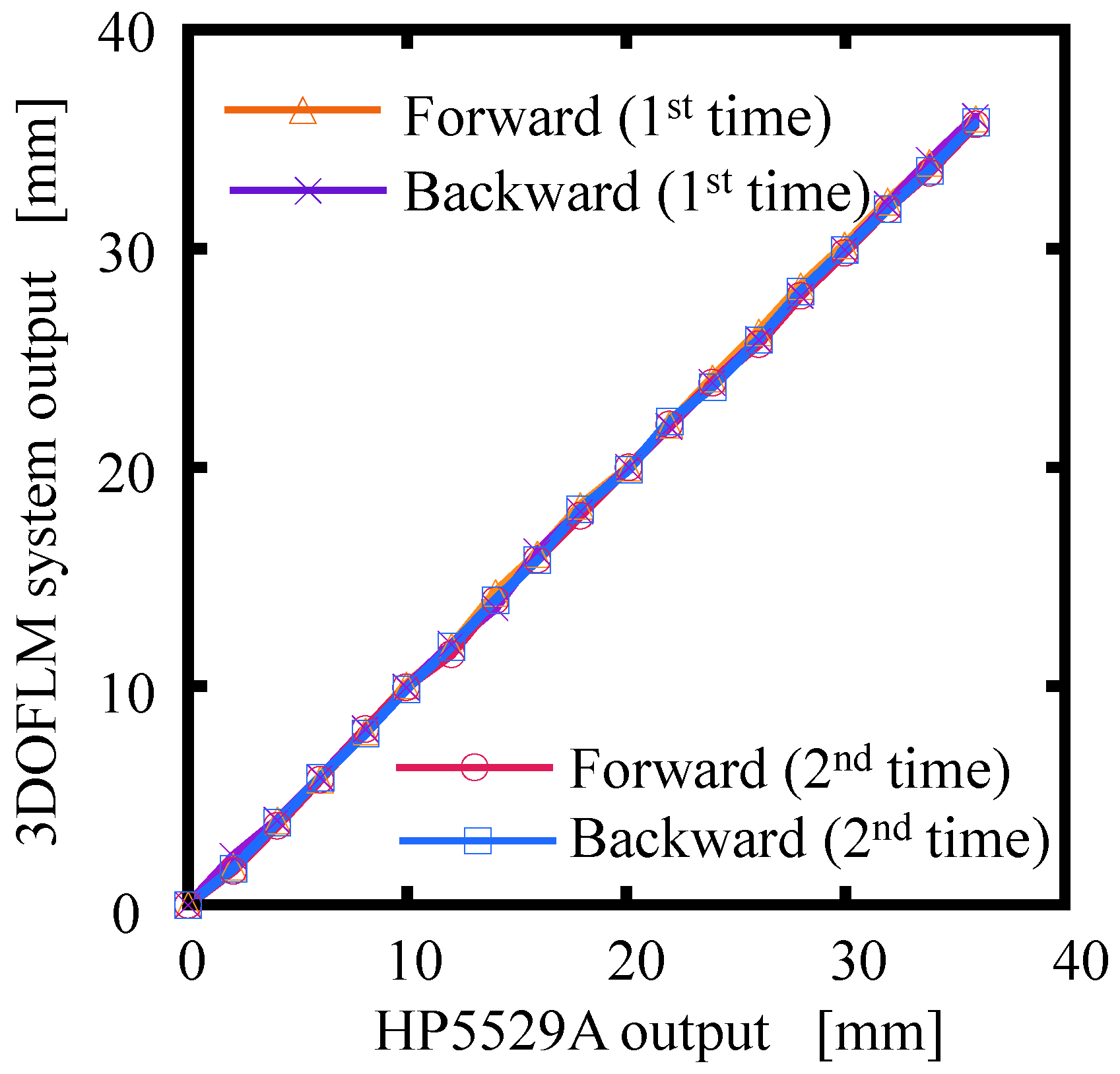
The displacement measurement range of the MMI kit was firstly confirmed using the HP5529A interferometer, which has a measurement range of 15 m. In experiments, the 3DOFLM and HP5529A systems were located on both sides of a linear stage (MSR 100, PARKER, Charlotte, USA), which was moved by a commanded step of 2 to 36 mm long.
Figure 9 shows the bi-directional displacement measurement results of the MMI kit and the HP5529A system, determined in duplicate. It can be seen that both outputs were in good agreement. Output sinusoidal signals in the form of a Lissajous circle were found to be very good and stable during motion, as shown in
Figure 10. The measuring range of the MMI kit was, thus, confirmed to be at least 36 mm, which is regarded as a long-stroke for a nanopositioning stage.
The displacement measurement accuracy of the 3DOFLM system was then calibrated by a commercial nanopositioning and nanomeasuring machine (NMM-1, SIOS Meßtechnik GmbH, Ilmenau, Germany), which has a positioning range of 25 mm in the
x- and
y-directions with sub-nanometer positioning accuracy. The misalignment error of the MMI kit and NMM-1 will induce a cosine error in the displacement measurement, which cannot be ignored in the nanometer range. Therefore, particular effort was put into aligning the laser beam of the MMI kit with the moving axis of the NMM-1. In this alignment experiment, a QPD was adopted to detect the two lateral motions of the moving table of the NMM-1 relative to the laser beam of the MMI kit. An angle mirror mount was applied to adjust the laser beam so that the beam spot was always close to the center of the QPD during the motion of the NMM-1.
Figure 11 shows the finally adjusted straightness error of the NMM-1 in the
x- and
y-directions. The maximum straightness error was evaluated to be 1.272 μm, and it corresponded to a cosine error of 0.04 nm on the displacement measurement in the range of 20 mm. Such a cosine error was small enough compared to the displacement of NMM-1 and was deemed negligible for the subsequent experiments.
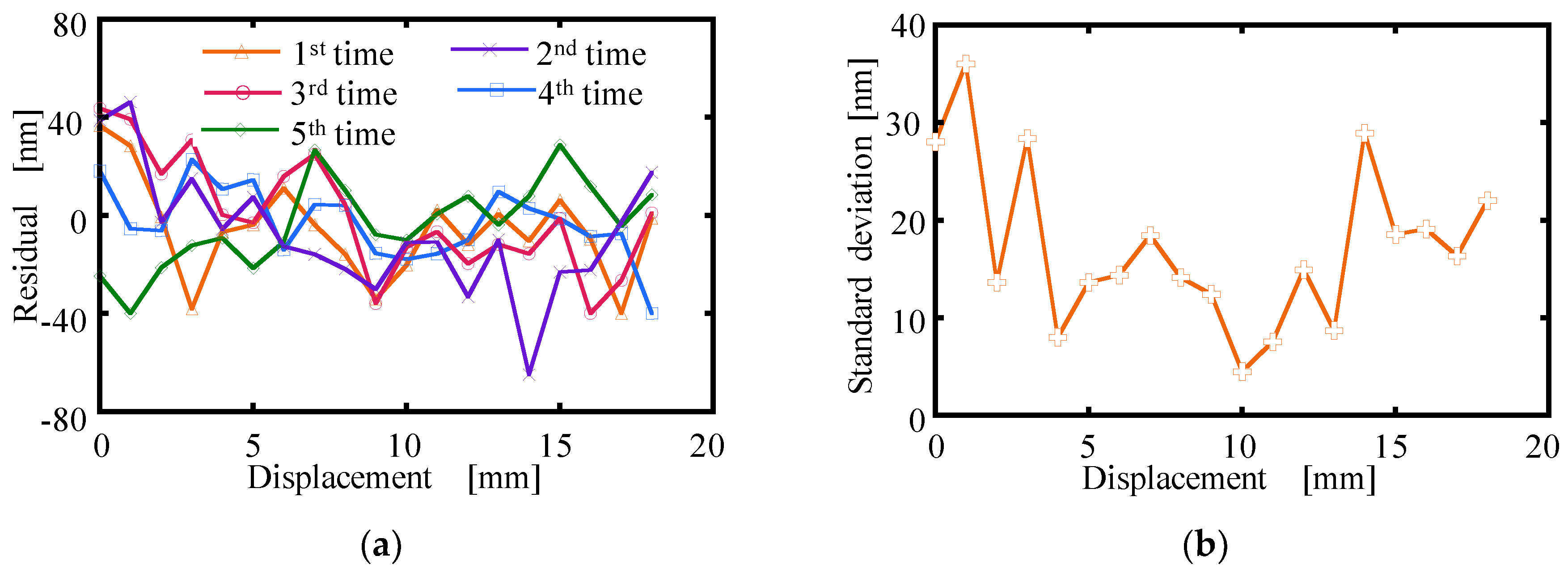
The calibration experiments without wavelength correction were then carried out with the nominal wavelength of the laser diode (i.e., 635 nm) given by the manufacturer. The displacement residuals between the 3DOFLM system and the NMM-1 system were evaluated within ±45 nm up to a travel of 18 mm, as shown in
Figure 12. The standard deviation of the displacement residuals for five measurements was estimated between 4.49 and 35.98 nm. The residual error between the 3DOFLM and NMM systems was deemed to be mainly caused by the incorrect laser diode wavelength of the MMI kit. Therefore, it is essential to correct the laser diode wavelength for better measurement accuracy.
3.3. Displacement Measurement with Wavelength Correction
Figure 13 shows simultaneous displacement measurement results of the NMM-1 system and the MMI kit with a step interval of 2 mm in the measurement distance of 20 mm. The actual calibrated wavelength (referred to as
λcal) was estimated by multiplying the nominal laser wavelength of 635 nm by the slope
kp of the fitted curve of the results in
Figure 13.
In the wavelength corrector kit, a transmission diffraction grating (Edmund optics, Barrington, USA) with a grating pitch of 1 μm was selected. The optical components used in AC2 were the same as that in AC1. The performance investigations of wavelength correction were firstly conducted.
Figure 14 shows the stability of AC2, which was employed to measure the drift of +1st order diffraction angle. As seen from
Figure 14, the maximum angle drift was measured as less than 1 arcsec. The laser wavelength variation caused by the variation of AC2 was evaluated to be 0.0037 nm by Equation (9).
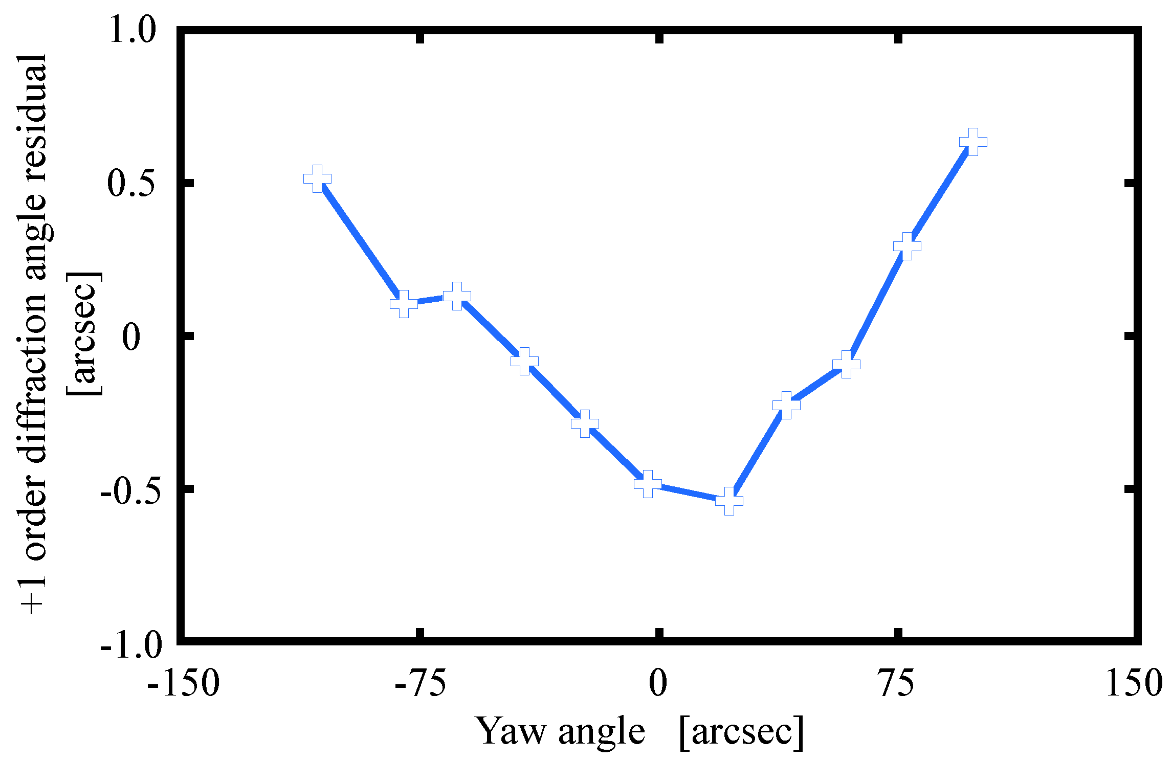
The angular measurement accuracy of AC2 was calibrated by the HP5529A system and the results are shown in
Figure 15. It can be seen that the angle residual for the range of ±100 arcsec was within ±0.5 arcsec. It is verified that AC2 was acceptable for sub-arcsecond precision angular error measurement.
The real-time laser diode wavelength was then evaluated based on Equation (9) according to the output of AC2. The wavelength measured by the self-wavelength correction is referred to as
λmea. The calibrated wavelength (
λcal) was obtained from the ratio of the actual displacement of NMM-1 system and the measured total phase change of the MMI kit, as given by Equation (7).
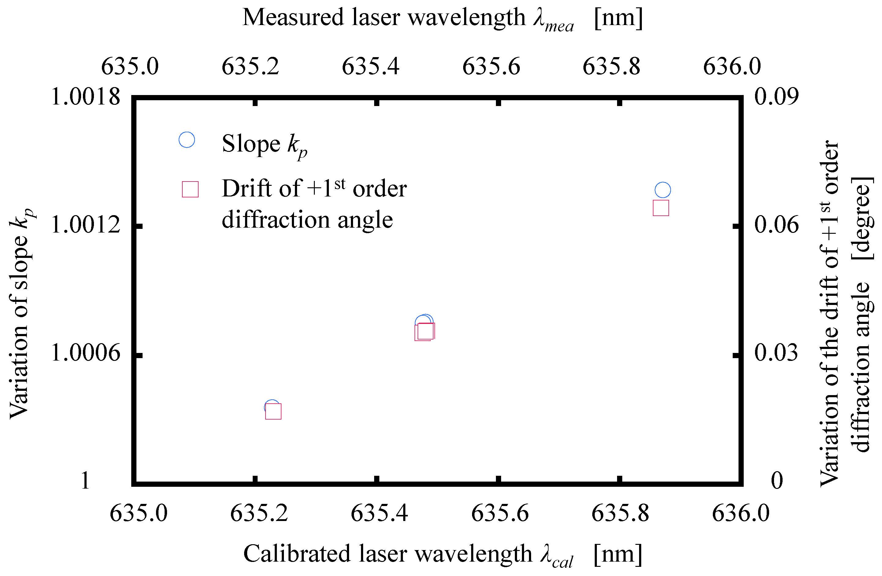
Figure 16 shows the relationship between the calibrated laser wavelength
λcal and the variation of slope
kp obtained from the displacement measurement results of the NMM-1 system and the MMI kit. The relationship between the measured laser wavelength
λmea and the variation of drift +1st order diffraction angle detected by AC2 was also plotted in
Figure 16. For the sake of comparison,
λcal and
λmea are listed in
Table 1. It is clearly seen that an order of 10
−6 accuracy was achieved in measured wavelength by the designed wavelength correction. It means that, if the 3DOFLM system measures a distance of 20 mm, the maximum measurement error, on average, would be estimated as about 20 nm.
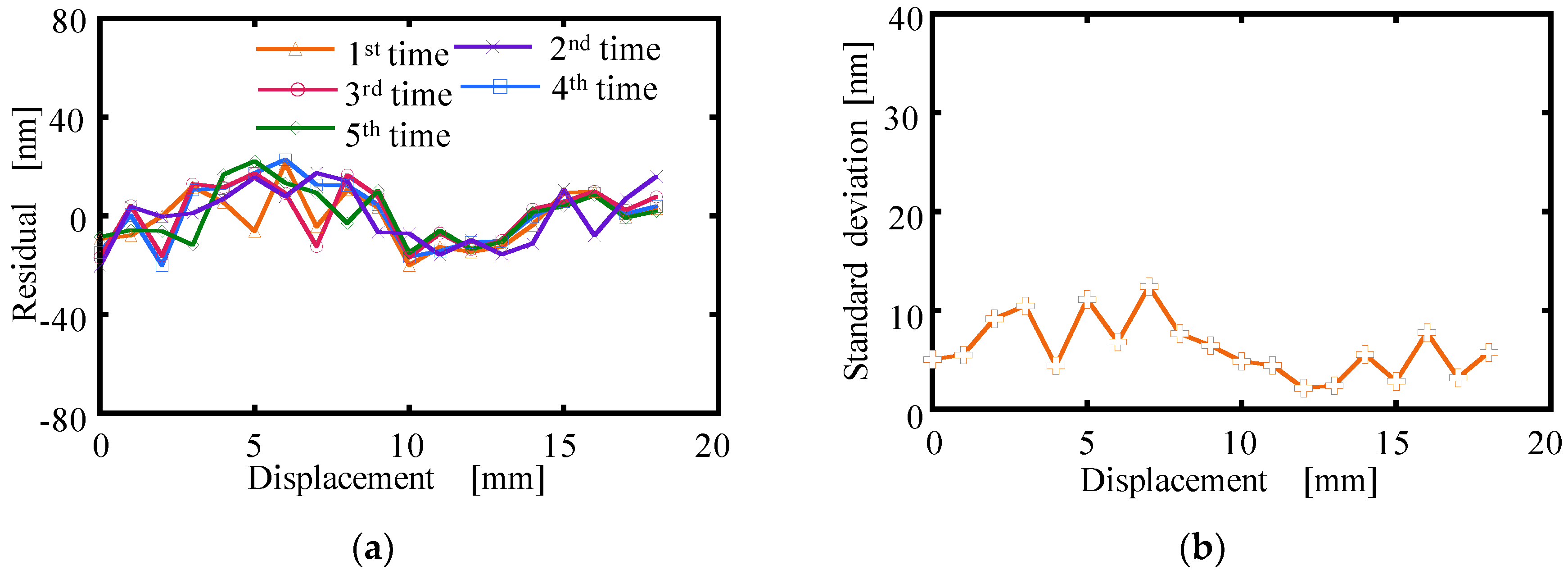
From the above experiments, it can be realized that a special feature of this 3DOFLM system is that it only needs to calibrate and store the nominal wavelength and the corresponding initial diffraction angle once using a reference. With these stored parameters, the system can automatically correct the wavelength by itself for the remaining measurements. The comparison results between the NMM-1 and 3DOFLM systems with wavelength correction are given in
Figure 17. It can be seen that, as expected, the measurement error of the 3DOFLM system falls within ± 25 nm, which was much smaller than that without wavelength correction in
Figure 12. The corresponding standard deviation of the measurement results was evaluated to be between 2.2 and 13.5 nm. The effectiveness of the wavelength corrector kit was, thus, verified.
3.4. Error Analysis
The measurement error of the 3DOFLM system was significantly reduced after correcting the laser diode wavelength. However, the measurement accuracy of the 3DOFLM system is still a little lower than commercial laser interferometers. The reason could be that the measurement accuracy of the wavelength corrector is influenced by the linearity error of the Lissagous circle, the incident beam angle and its drift, thermal deformation of the grating pitch, etc., which were not considered in this study. As a report for the first step of the research, this paper focuses on the design and construction of the 3DOFLM system. The improvement of wavelength measurement accuracy will be carried out in the next step of the research for the proposal of a practical application of the nanopositioning stage.


