A Multi-Tone Sound Absorber Based on an Array of Shunted Loudspeakers

1
Key Laboratory of Modern Acoustics (MOE), Institute of Acoustics, Nanjing University, Nanjing 210093, China
2
Centre for Audio, Acoustics and Vibration, Faculty of Engineering and IT, University of Technology, Sydney, NSW 2007, Australia
*
Author to whom correspondence should be addressed.
Appl. Sci. 2018, 8(12), 2484; https://doi.org/10.3390/app8122484
Submission received: 1 November 2018
/
Revised: 23 November 2018
/
Accepted: 23 November 2018
/
Published: 4 December 2018
(This article belongs to the Special Issue Active and Passive Noise Control)
Abstract
:It has been demonstrated that a single shunted loudspeaker can be used as an effective low frequency sound absorber in a duct, but many shunted loudspeakers have to be used in practice for noise reduction or reverberation control in rooms, thus it is necessary to understand the performance of an array of shunted loudspeakers. In this paper, a model for the parallel shunted loudspeaker array for multi-tone sound absorption is proposed based on a modal solution, and then the acoustic properties of a shunted loudspeaker array under normal incidence are investigated using both the modal solution and the finite element method. It was found that each shunted loudspeaker can work almost independently where each unit resonates. Based on the interaction analysis, multi-tone absorbers in low frequency can be achieved by designing multiple shunted loudspeakers with different shunt circuits respectively. The simulation and experimental results show that the normal incidence sound absorption coefficient of the designed absorber has four absorption peaks with values of 0.42, 0.58, 0.80, and 0.84 around 100 Hz, 200 Hz, 300 Hz, and 400 Hz respectively.
1. Introduction
The shunted loudspeaker, which consists of a closed-box loudspeaker and a shunt circuit, was first proposed for resonant acoustic field control in 2007 [1]. The acoustic impedance at the loudspeaker diaphragm and the resulting sound absorption coefficient can be adjusted by alternating the electric parameters in the shunt circuit, so the shunted loudspeaker can be implemented for noise control especially at low frequencies [2,3,4].
Early studies on the shunted loudspeaker mainly focus on normal sound absorption performance. Černík et al. studied the effect of the shunt circuit on the sound reflecting performance of a shunted loudspeaker in an impedance duct [2]. Zhang et al. employed the negative impedance converter to counter the D.C. resistance and voice coil inductance of the loudspeaker to broaden the sound absorption bandwidth [5]. Tao et al. proposed constituting a thin compound broadband absorber by placing the shunted loudspeaker at the back of a micro-perforated panel [6]. Jing et al. designed a shunt speaker with a sound absorption coefficient above 0.9 at both 100 Hz and 200 Hz to control the noise of the power transformer [7]. Cho et al. replaced the closed box with a vented enclosure to enhance the sound absorption performance at low frequency [8]. Boulandet et al. adopted the response surface method to optimize the parameters of the shunted loudspeaker (such as the moving mass, the enclosure volume, the filling density of mineral fiber, and the electrical load value) [9]. In the studies above, analog components were used in the shunt circuit, and it was difficult to adjust the electrical impedance precisely. Boulandet et al. employed the real-time field programmable gate array module and the voltage-controlled current source to constitute the shunt circuits [10]. Rivet et al. proposed a hybrid impedance control architecture for an electroacoustic absorber that combines a microphone-based feedforward control with a current driven electro dynamic loudspeaker system [11]. Considering the resonance characteristics of the mechanical system of the loudspeaker, the shunted loudspeaker is a typical resonant sound absorber with adjustable feedback impedance [12,13,14].
For implementation, the performance of the array of shunted loudspeakers needs to be further investigated. A linear array of 10 shunted loudspeakers was placed in the reverberant chamber, and a sound pressure attenuation of 14 dB was achieved at 34.9 Hz [15]. Four shunted loudspeakers with surface area of 0.05 m2 were placed in the corners of the rectangular room with dimensions of 3 × 5.6 × 3.53 m3 to reduce the sound pressure level between 70 Hz and 100 Hz [16]. Thirty 50 × 50 mm shunted loudspeaker cells were assembled as liners inside a pipeline with air flow, and the obtained insertion loss was 16 dB at the target frequency [17]. A surface array of shunted loudspeakers could control the refracted direction of the incident sound around 350 Hz [18]. However, the sound absorption performance of the surface array of shunted loudspeakers has not been investigated.
In this paper, a modal expansion method is proposed to calculate the normal sound absorption coefficient of the array of shunted loudspeakers with different acoustic impedances. The finite element model is further employed to validate the accuracy of the proposed method. Simulations show that each shunted loudspeaker can work almost independently. An experiment was conducted in the impedance duct with four different shunted loudspeakers to validate the feasibility of achieving multi-tone sound absorption.
2. Theory
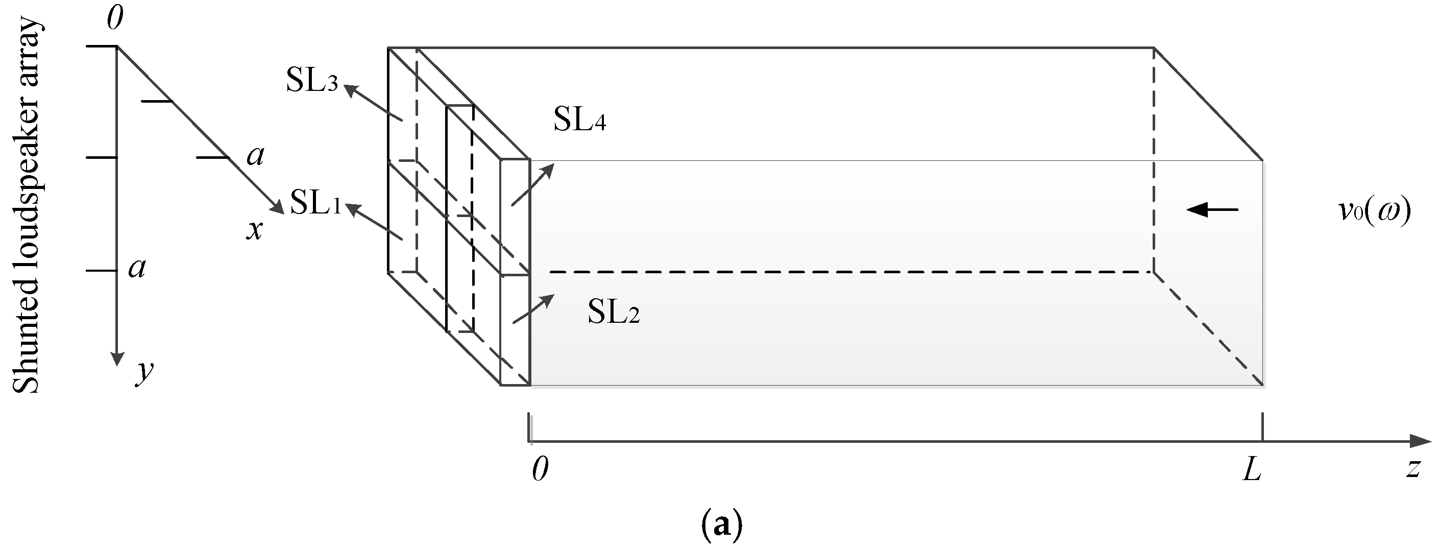
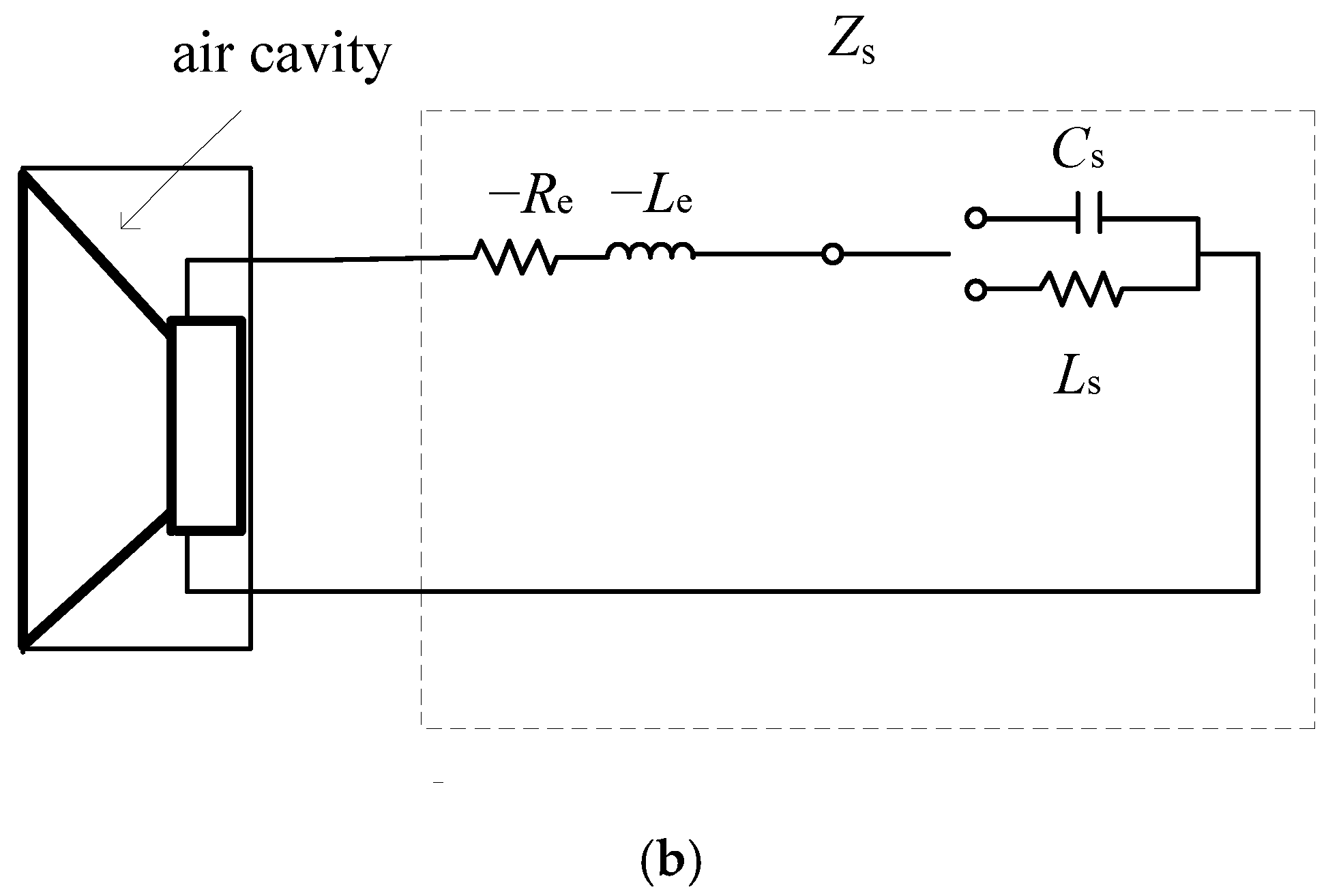
The schematic of the shunted loudspeaker array is presented in Figure 1a, where four shunted loudspeakers with equal areas are installed at the left terminal z = 0 of a square impedance duct. A plane wave is incident normally on the right terminal at z = L with a constant particle velocity v0(ω). Each shunt loudspeaker (named as SL1 to SL4) consists of a closed-box loudspeaker and a shunt circuit connected to the loudspeaker’s terminals. The length of the duct cross section is a, and the length of the front face of each shunted loudspeaker unit is a/2 respectively. The shunt circuit is shown in Figure 1b, where the negative resistance −Re and negative inductance −Le are used to counteract the D.C. resistance RE and voice coil inductance LE of the loudspeaker respectively. The capacitance Cs and inductance Ls can be switched according to the design targets.
The specific acoustic impedance of the ith shunted loudspeaker (i = 1, 2, 3, 4) is [4,19]
where ω is the angular frequency, Rms is the mechanical resistance of the driver suspension losses of the loudspeaker, S0 is the effective surface area of the driver cone of the loudspeaker, Mms is the mechanical mass of the driver cone (including reactive air load) of the loudspeaker, Cms is the mechanical compliance of the driver suspension of the loudspeaker, Cab = V/ρ0c02 is the equivalent acoustic capacitance due to the back cavity of the loudspeaker, V is the volume of the back cavity, ρ0 and c0 are the air density and sound velocity respectively, B is the magnetic flux density of the loudspeaker driver, l is the voice coil length, and Zs is the electrical impedance of the shunt circuit.
Omitting the time harmonic factor , the acoustic field inside the impedance duct shown in Figure 1a can be expanded using the modal solution as
where q is the mode index, k0 = ω/c0 and kq = qπ/a are the total wavenumber and the lateral wavenumber of the qth mode respectively, is the qth mode function, S = a2 is the section area of the duct, Aq and Bq are the qth mode coefficients of the incident wave and reflected wave respectively.
The boundary conditions at z = 0 and z = L are
where vz(x, y, z, ω) is the velocity in the z direction, and the specific acoustic impedance is
Substituting p(x, y, z, ω) in Equation (2) into the boundary condition in Equations (3) and (4), the following is obtained:
where is the wavenumber of the qth mode along the z direction and δ0q is the Kronecker delta function. Exploiting the orthogonality of the normal modes, Equation (7) can be simplified as
where μ and λ are the mode indexes, kμ = μπ/a and kλ = λπ/a are the lateral wavenumbers of the μth and λth modes respectively, Aμ and Bμ are the μth mode coefficients of the incident wave and reflected wave respectively, kμ = μπ/a is the lateral wavenumber of the μth mode, is the wavenumber of the μth mode along z direction, is the μth mode function. The factor Z0qμ mathematically measures the coupling of different modes caused by the inhomogeneity of the acoustical impedance at z = 0. The mode coupling makes it hard to obtain an analytical solution in a compact closed form. However, it is possible to approach the exact solution through iterations.
Assume the inhomogeneity is quite weak such that all the high-order modes with q not being zero can be neglected, the plane-wave mode ψ0(x,y,k0) is preserved and the coefficients A0 and B0 are derived as
where the factor Z000 is calculated in Equation (9) when q and μ are taken as zero.
Assume that the inhomogeneity of the shunted loudspeaker array causes the plane-wave mode to be coupled to high-order modes while the high-order modes themselves are not coupled with each other, Equation (8) can be simplified as
where the factors Z0μμ and Z00μ are calculated in Equation (9) when q is taken as μ and 0 respectively.
Substituting A0, B0 in Equations (10) and (11) into Equation (12), the coefficients of high-order modes can be calculated as
The normal incidence sound absorption coefficient α can be calculated by
where pr and pin are reflected pressure and incident pressure at z = 0. It is clear that the more coupling measures Z0qμ that are adopted; the more precise can be the results obtained.
3. Simulations
In this section, the acoustic properties of four parallel arranged shunted loudspeakers are investigated by both the proposed method and the finite element method. The same loudspeaker is adopted in each shunted loudspeaker, and the measured Thiele–Small (TS) parameters of the loudspeaker are listed in Table 1. The resonance frequencies of the shunted loudspeakers are chosen as 100 Hz, 200 Hz, 300 Hz, and 400 Hz, and the designed shunt circuit parameters are listed in Table 2.
The sound absorption coefficient of the array composed of SL1–SL4 can be calculated by the finite element model built in the commercial software (Comsol Multiphysics v5.3) as shown in Figure 2. The plane at z = 1.8 m is set as a plane wave incident surface and e incident sound pressure is 1 Pa. The bottom surface at z = 0 m is uniformly divided into four parts, which are defined as impedance boundaries. The size of each impedance boundary is the same as the effective area in Table 1. Set the impedance at (0 < x < a/2, a/2 < y < a) of SL1 unit boundary as Z1, the impedance at (a/2 < x < a, a/2 < y < a) of SL2 unit boundary as Z2, the impedance at (0 < x < a/2, 0 < y < a/2) of SL3 unit boundary as Z3, and the impedance at (a/2 < x < a, 0 < y < a/2) of SL4 unit boundary as Z4. The element size is selected as an extremely fine mesh size. The free tetrahedral mesh consists of 24,973 domain elements, 3344 boundary elements, and 315 edge elements, with the number of degrees of freedom as 36536. The absorption coefficient is calculated by
where Er is the reflected energy and Ein is the incident energy at the surface z = 0.
The solid curve in Figure 3 shows the normal incidence absorption coefficient of the shunted loudspeaker array by using the proposed method in Section 2. Four resonance frequencies occur at 100 Hz, 200 Hz, 300 Hz, 400 Hz, where the sound absorption coefficients are all 1.00. The dashed curve in Figure 3 reveals the result by using the Finite Element Method (FEM), where the frequency deviations at the resonance frequencies are 0 Hz, 5 Hz, 6 Hz, and 4 Hz, respective due to a simulation error in Comsol.
The dotted curves reflect the sound absorption coefficients of SL1–SL4 units, where the resonance frequencies are 100 Hz, 200 Hz, 300 Hz, 400 Hz of each unit respectively. Comparing with the resonance frequencies of the array, it is revealed that each shunted loudspeaker almost works independently. Therefore, a multi-tone noise absorber can be designed by using multiple shunted loudspeakers with different resonance frequencies in the same plane, where each unit can be designed independently.
The acoustic intensity of the shunted loudspeaker array at four resonance frequencies is shown in Figure 4, where the volume density (directions) of the red arrows shows the magnitude (directions) of the sound intensity. Most part of the acoustic energy is “attracted” toward SL1 at 100 Hz, which is at the resonance frequency of SL1. Similarly, most of the acoustic energy is “attracted” toward SL2–SL4 at the resonance frequencies of SL2–SL4 respectively. It is observed that at the resonant frequency of a particular shunted loudspeaker unit, the acoustic energy flows towards the unit at resonance. However, the other shunted loudspeaker units are also working as absorbers although the sound intensity near them is rather weak. This is intuitive evidence to demonstrate that all the shunted loudspeaker units work cooperatively as an entire piece.
From the analysis above, the normal incidence absorption coefficients of the shunted loudspeaker array calculated with the analytical solution agree reasonably well with the results obtained with the finite element method. The most part of the acoustic energy is “attracted” toward the shunted loudspeaker unit at its resonance frequency. Therefore, a multi-tone noise absorber can be realized by designing multiple shunted loudspeakers with different resonance frequencies.
The optimal system can be achieved by designing each shunt loudspeaker unit first and then combing all the units together. In the design of each shunt loudspeaker the peak frequency of its sound absorption coefficient can be adjusted by choosing the proper value of Cs or Ls in Figure 1b, and the peak value of its sound absorption coefficient can be adjusted by choosing the loudspeaker with the proper mechanical resistance Rms.
4. Experimental
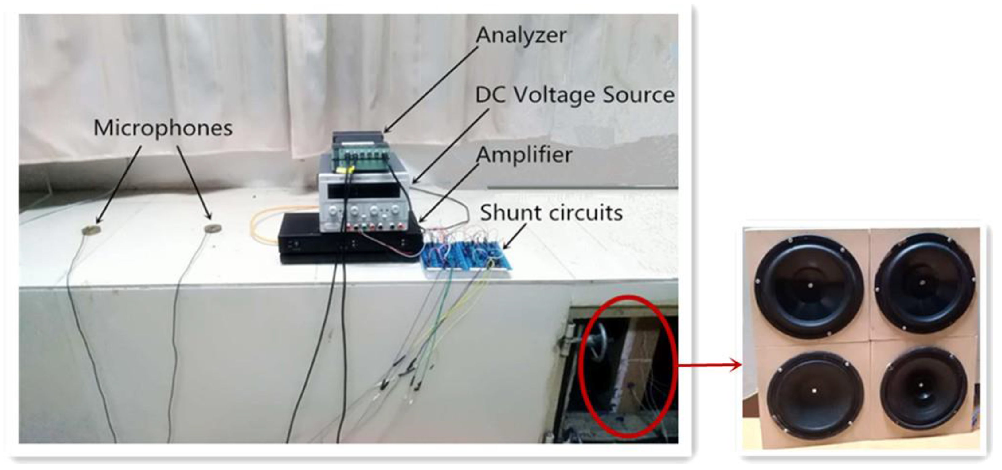
The experimental setup in an acoustic impedance duct is shown in Figure 5, where the array of four shunted loudspeakers is placed at the right end. The cross section of the duct is about 0.40 m × 0.40 m and the cut-off frequency is 430 Hz. A source loudspeaker is located at the left end of the duct (It is about 7 m away from the shouted loudspeaker array and is not seen in Figure 5) and driven through the amplifier. The DC voltage source is used to supply the power for the negative impedance converters in the shunt circuits. The sound absorption coefficient was measured using the two-microphone transfer function method according to ISO 10534-2 with a B&K PULSE 3560B analyzer [20]. The parameters to set up are as follows: the sampling rate is 25.6 kHz, and the frequency resolution is set as 1 Hz; the microphone spacing is 0.35 m; the distance from the right microphone to the sample is 1.32 m; the distance from the left microphone to the source is 3.64 m; a random signal is set as the input to the source with the voltage level of 0.07 Vrms to ensure that the signal to noise ratio is above 10 dB.
An optimal system was designed based on the analysis in Section 3. The Thiele–Small parameters and dimensions of each loudspeaker are listed in Table 3, Table 4, Table 5 and Table 6, where the cavity depth is optimized at 7.5 cm. However, the mechanical resistance Rms is not equal to the optimal value ρ0c0S02/S for the maximal sound absorption peak, because the number of the loudspeaker samples we have is limited. The shunt circuit configuration for the four loudspeakers is listed in Table 7. Theoretically, the resonance of each shunted loudspeaker unit could be adjusted to any frequency. However, considering the nonlinearity of the loudspeaker [21], a more accurate formulation of the impedance Ze is B2l2/S0/[RE + jωLE + 1/(1/R2 + 1/L2) + Zs], where R2 is the electrical resistance due to the eddy current losses and L2 is the para-inductance of the voice coil. Therefore, the adjustment of the resonance frequency of the shunted loudspeaker has constraints. In practical, the inductance element in the shunt circuit generates parasitic resistance. By using the ohmmeter to measure the value, negative resistance is employed to cancel the parasitic resistance.
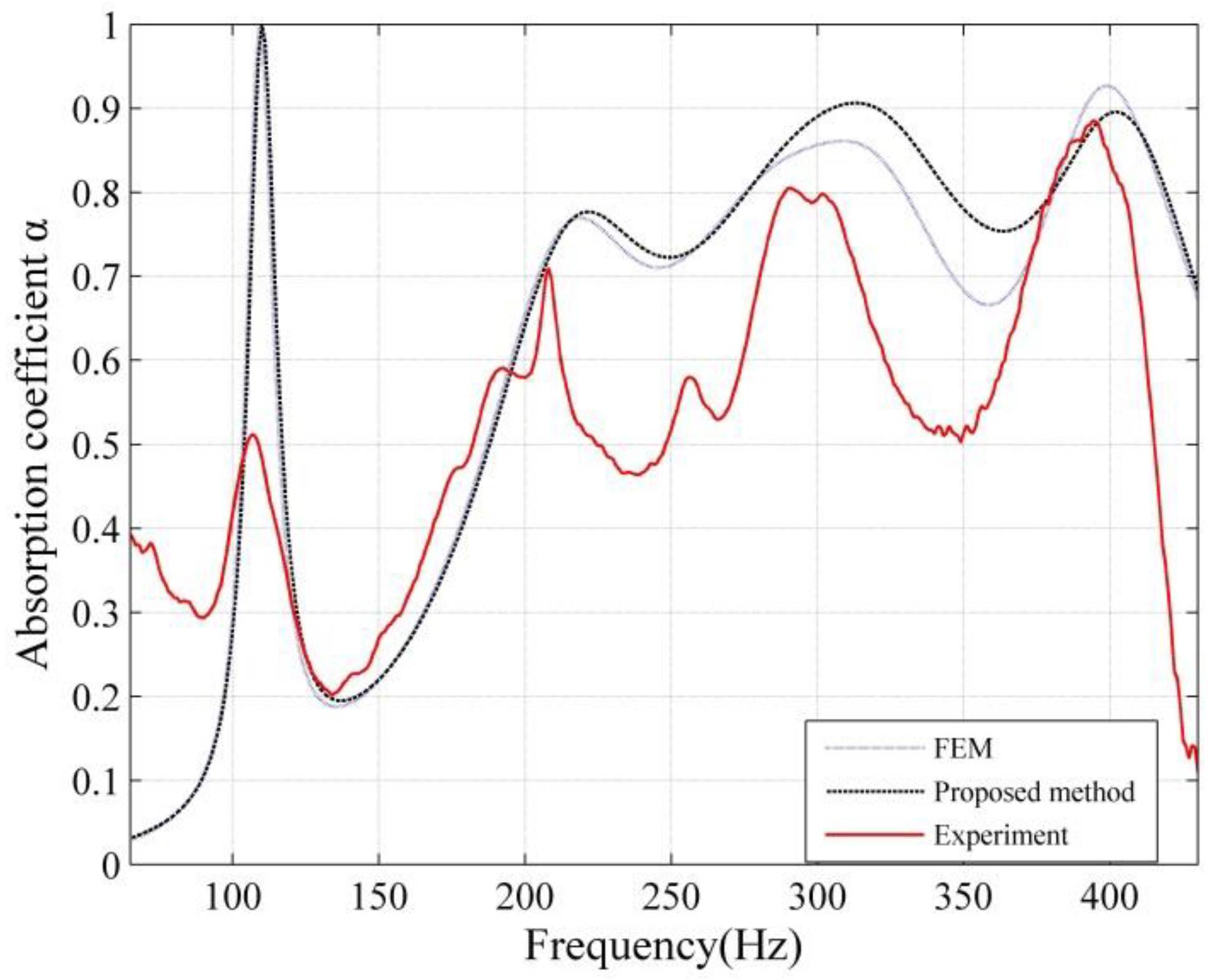
Take the shunt circuit parameters in Table 7 and the TS parameters and dimensions in Table 3, Table 4, Table 5 and Table 6 into Equation (1), the specific acoustic impedances of each shunted loudspeaker are then calculated. It should be noted that the measured sound absorption is contributed to by both the loudspeaker diaphragm and the front surface of the closed-box, because the diaphragm area is smaller than the cross section of the duct. Therefore, the impedance Zi is corrected by the area ratio factor a2/4S0. Substituting the corrected impedance Zi(a2/4S0) into Equation (5), the sound absorption coefficient can be calculated according to Equation (15) and shown as the dashed line in Figure 6. The resonance frequencies are at 110 Hz, 222 Hz, 313 Hz, 402 Hz, where the sound absorption coefficients are 1.00, 0.78, 0.91, and 0.90 respectively. Meanwhile, the results by using the FEM method are shown in the dotted curve, where the resonance frequencies are at 109 Hz, 219 Hz, 308 Hz, 399 Hz and the sound absorption coefficients are 1.00, 0.77, 0.86, and 0.93 respectively.
The measured sound absorption coefficient of the shunted loudspeaker array is shown in Figure 6 (the solid curve), where the sound absorption coefficients at 100 Hz, 200 Hz, and 300 Hz are 0.42, 0.58, 0.80, and 0.84 respectively, with the resonance peaks being at 107 Hz, 208 Hz, 302 Hz, and 395 Hz respectively. The frequency shift of the absorption peaks between the simulation and the experiment results is not more than 11 Hz, which may be caused by the measurement precision of the loudspeaker TS parameters and the electronic components in the shunt circuit in the experiments. The differences of the peak values of the sound absorption coefficient between experimental and simulation results may be due to extra parasitic resistances of the electronic components.
5. Conclusions
This paper investigates the feasibility of designing thin multi-tone sound absorbers based on an analog circuit shunted loudspeaker array. A model for the parallel shunted loudspeaker array for multi-tone sound absorption is proposed based on a modal solution, and then the acoustic properties of a shunted loudspeaker array under normal incidence are investigated using both the modal solution and the finite element method. The physical mechanism in a finite standing wave duct was investigated, and it was found that the acoustic energy of a different frequency is “attracted” toward the corresponding shunted loudspeaker at that specific frequency and converted into electrical energy. The measured sound absorption coefficient of the designed prototype has four peaks with values of 0.42, 0.58, 0.80, and 0.84 around 100 Hz, 200 Hz, 300 Hz, and 400 Hz. Further work includes investigation of the sound absorption of the proposed multi-tone absorber array under oblique incidence and in a reverberation room.
Author Contributions
X.-J.Q. initiated and developed the ideas related to this research work; C.-N.C. and J.-C.T. developed novel methods, derived relevant formulations, and carried out numerical analyses and experimental analyses. C.-N.C. wrote the paper draft under J.-C.T. and X.-J.Q.’s guidance; and C.-N.C. finalized the paper.
Funding
This research was funded by the National Science Foundation of China with the grant number 11474163 and 11874218, and the Australian Research Council with the grant numberLP140100987.
Acknowledgments
The authors would also like to thank Li Ruiqi for the help in the formula derivation.
Conflicts of Interest
The authors declare no conflict of interest.
References
- Fleming, A.J.; Niederberger, D.; Moheimani, S.R.; Morari, M. Control of resonant acoustic sound fields by electrical shunting of a loudspeaker. IEEE Trans. Control Syst. Technol. 2007, 15, 689–703. [Google Scholar] [CrossRef]
- Cerník, M.; Mokrý, P. Sound reflection in an acoustic impedance tube terminated with a loudspeaker shunted by a negative impedance converter. Smart Mater. Struct. 2012, 21, 115016–115024. [Google Scholar] [CrossRef]
- Tang, J.; Wang, K.W. Active-passive hybrid piezoelectric networks for vibration control: Comparisons and improvement. Smart Mater. Struct. 2001, 10, 794–806. [Google Scholar] [CrossRef]
- Zhang, Y.M. Dynamic Mass Modification by Electric Circuits. Master’s Thesis, The University of Hong Kong, Hong Kong, China, 2012. [Google Scholar]
- Zhang, Y.; Chan, Y.J.; Huang, L. Thin broadband noise absorption through acoustic reactance control by electro-mechanical coupling without sensor. J. Acoust. Soc. Am. 2014, 135, 2738–2745. [Google Scholar] [CrossRef] [PubMed] [Green Version]
- Tao, J.; Jing, R.; Qiu, X. Sound absorption of a finite micro-perforated panel backed by a shunted loudspeaker. J. Acoust. Soc. Am. 2014, 135, 231–238. [Google Scholar] [CrossRef] [PubMed]
- Tao, J.; Cong, C.; Qiu, X. Thin low frequency sound absorbers based on shunted loudspeakers. J. Acoust. Soc. Am. 2016, 140, 2993. [Google Scholar] [CrossRef]
- Cho, Y.; Wang, S.; Hyun, J.; Oh, S.; Goo, S. Analysis of sound absorption performance of an electroacoustic absorber using a vented enclosure. J. Sound Vib. 2018, 417, 110–131. [Google Scholar] [CrossRef]
- Boulandet, R.; Lissek, H. Optimization of electroacoustic absorbers by means of designed experiments. Appl. Acoust. 2010, 71, 830–842. [Google Scholar] [CrossRef] [Green Version]
- Boulandet, R.; Rivet, E.; Lissek, H. Sensorless electroacoustic absorbers through synthesized impedance control for damping low-frequency modes in cavities. Acta Acust. United Acust. 2016, 102, 696–704. [Google Scholar] [CrossRef]
- Rivet, E.; Karkar, S.; Lissek, H. Broadband low-frequency electroacoustic absorbers through hybrid sensor-/shunt-based impedance control. IEEE Trans. Control Syst. Technol. 2017, 25, 63–72. [Google Scholar] [CrossRef]
- Lissek, H.; Boulandet, R.; Fleury, R. Electroacoustic absorbers: Bridging the gap between shunt loudspeakers and active sound absorption. J. Acoust. Soc. Am. 2011, 129, 2968–2978. [Google Scholar] [CrossRef] [PubMed]
- Boulandet, R. Tunable Electroacoustic Resonators through Active impedance Control of Loudspeakers. Ph.D. Thesis, Swiss Federal Institute of Technology in Lausanne, Zurich, Switzerland, 2012. [Google Scholar]
- Boulandet, R.; Lissek, H. Toward broadband electroacoustic resonators through optimized feedback control strategies. J. Sound Vib. 2014, 333, 4810–4825. [Google Scholar] [CrossRef] [Green Version]
- Lissek, H.; Boulandet, R.; Moreau, A.S. Practical active and semi-active strategies for the control of room acoustics in the low frequency range. In Proceedings of the INTER-NOISE 2010, Lisbon, Portugal, 13–16 June 2010. [Google Scholar]
- Rivet, E.; Boulandet, R.; Lissek, H.; Rigas, I. Study on room modal equalization at low frequencies with electroacoustic absorbers. In Proceedings of the Acoustics 2012, Nantes, France, 23–27 April 2012. [Google Scholar]
- Matten, G.; Ouisse, M.; Collet, M.; Karkar, S.; Lissek, H.; Boulandet, R.; Versaevel, M. Design and experimental validation of an active acoustic liner for aircraft engine noise reduction. In Proceedings of the MEDYNA 2017, Sevilla, Spain, 25–27 April 2017. [Google Scholar]
- Lissek, H.; Rivet, E.; Laurence, T.; Fleury, R. Toward wideband steerable acoustic metasurfaces with arrays of active electroacoustic resonators. J. Appl. Phys. 2018, 123, 091714. [Google Scholar] [CrossRef] [Green Version]
- Eargle, J. Loudspeaker Handbook; Kluwer Academic Publishers: Norwell, MA, USA, 2003. [Google Scholar]
- International Organization for Standardization (ISO). Acoustics—Determination of Sound Absorption Coefficient and Impedance in Impedance tubes. Part 2: Transfer Function Method; ISO 10534-2; ISO: Geneva, Switzerland, 1998. [Google Scholar]
- Vanderkooy, J. A Model of Loudspeaker Driver Impedance Incorporating Eddy Currents in the Pole Structure; University of Waterloo: Waterloo, ON, Canada, 1988. [Google Scholar]
Figure 1.
(a) A schematic of the shunted loudspeaker array set at the end of an impedance duct; (b) the equivalent circuit of a shunt loudspeaker unit.
Figure 1.
(a) A schematic of the shunted loudspeaker array set at the end of an impedance duct; (b) the equivalent circuit of a shunt loudspeaker unit.


Figure 2.
The finite element model of four shunted loudspeakers in parallel.

Figure 3.
The normal incidence sound absorption coefficients by analytical solution and the finite element model method: SL1 unit (magenta dotted line marked with plus sign), SL2 unit (green dotted line marked with upward-pointing triangle), SL3 unit (red dotted line marked with solid circle), SL4 unit (cyanine dotted line marked with blank circle), shunted loudspeaker array by analytical solution (black solid line), shunted loudspeaker array by FEM (blue dashed line).

Figure 4.
The acoustic intensity of parallel shunted loudspeaker array (a) at 100 Hz; (b) at 200 Hz; (c) at 300 Hz; (d) at 400 Hz.
Figure 4.
The acoustic intensity of parallel shunted loudspeaker array (a) at 100 Hz; (b) at 200 Hz; (c) at 300 Hz; (d) at 400 Hz.

Figure 5.
Measurement setup of the shunted loudspeaker array.

Figure 6.
Measured and calculated sound absorption coefficients of the shunted loudspeaker array.


Table 1.
Measured Thiele–Small (TS) parameters and dimensions of a closed-box loudspeaker unit.
| Parameter | Notation | Value | Unit |
|---|---|---|---|
| DC resistance | RE | 32.00 | Ω |
| Inductance of coil | LE | 7.24 | mH |
| Moving mass | Mms | 15.25 | g |
| Mechanical resistance | Rms | 1.57 | kg/s |
| Mechanical compliance | Cms | 0.67 | mm/N |
| Force factor | Bl | 17.12 | T·m |
| Effective area | S0 | 1.51 × 10⁻² | m2 |
| Back cavity volume | V | 2.2 × 10⁻³ | m3 |
| Cavity depth | D | 7.5 | cm |
Table 2.
Shunt circuit parameters used in the simulation of the shunted loudspeaker (SL) array.
| SL1 | SL2 | SL3 | SL4 | |
|---|---|---|---|---|
| R (Ω) | −31.95 | −31.95 | −31.95 | −31.95 |
| L (mH) | −7.23 | −7.23 | −7.23 | −7.23 |
| Ls (mH) | - | 37.19 | 7.69 | 3.62 |
| Cs (μF) | 87 | - | - | - |
Table 3.
Measured Thiele–Small (TS) parameters and dimensions of a closed-box loudspeaker (SL1 unit).
Table 3.
Measured Thiele–Small (TS) parameters and dimensions of a closed-box loudspeaker (SL1 unit).
| Parameter | Notation | Value | Unit |
|---|---|---|---|
| DC resistance | RE | 32.12 | Ω |
| Inductance of coil | LE | 7.24 | mH |
| Moving mass | Mms | 15.25 | g |
| Mechanical resistance | Rms | 1.15 | kg/s |
| Mechanical compliance | Cms | 0.67 | mm/N |
| Electrical resistance due to eddy current losses | R2 | 39.50 | Ω |
| Para-inductance of voice coil | L2 | 6.75 | mH |
| Force factor | Bl | 17.12 | T·m |
| Effective area | S0 | 1.51 × 10⁻² | m2 |
| Back cavity volume | V | 2.2 × 10⁻³ | m3 |
| Cavity depth | D | 7.5 | cm |
Table 4.
Measured TS parameters and dimensions of a closed-box loudspeaker (SL2 unit).
| Parameter | Notation | Value | Unit |
|---|---|---|---|
| DC resistance | RE | 5.71 | Ω |
| Inductance of coil | LE | 0.37 | mH |
| Moving mass | Mms | 15.19 | g |
| Mechanical resistance | Rms | 1.31 | kg/s |
| Mechanical compliance | Cms | 0.83 | mm/N |
| Electrical resistance due to eddy current losses | R2 | 1.11 | Ω |
| Para-inductance of voice coil | L2 | 0.33 | mH |
| Force factor | Bl | 5.05 | T·m |
| Effective area | S0 | 1.51 × 10⁻² | m2 |
| Back cavity volume | V | 1.2 × 10⁻³ | m3 |
| Cavity depth | D | 7.5 | cm |
Table 5.
Measured TS parameters and dimensions of a closed-box loudspeaker (SL3 unit).
| Parameter | Notation | Value | Unit |
|---|---|---|---|
| DC resistance | RE | 6.98 | Ω |
| Inductance of coil | LE | 0.24 | mH |
| Moving mass | Mms | 7.72 | g |
| Mechanical resistance | Rms | 0.94 | kg/s |
| Mechanical compliance | Cms | 0.27 | mm/N |
| Electrical resistance due to eddy current losses | R2 | 1.57 | Ω |
| Para-inductance of voice coil | L2 | 0.31 | mH |
| Force factor | Bl | 5.21 | T·m |
| Effective area | S0 | 1.51 × 10⁻² | m2 |
| Back cavity volume | V | 1.4 × 10⁻³ | m3 |
| Cavity depth | D | 7.5 | cm |
Table 6.
Measured TS parameters and dimensions of a closed-box loudspeaker (SL4 unit).
| Parameter | Notation | Value | Unit |
|---|---|---|---|
| DC resistance | RE | 7.31 | Ω |
| Inductance of coil | LE | 0.33 | mH |
| Moving mass | Mms | 10.38 | g |
| Mechanical resistance | Rms | 1.02 | kg/s |
| Mechanical compliance | Cms | 0.29 | mm/N |
| Electrical resistance due to eddy current losses | R2 | 1.41 | Ω |
| Para-inductance of voice coil | L2 | 0.25 | mH |
| Force factor | Bl | 5.60 | T·m |
| Effective area | S0 | 1.51 × 10⁻² | m2 |
| Back cavity volume | V | 1.4 × 10⁻³ | m3 |
| Cavity depth | D | 7.5 | cm |
Table 7.
Shunt circuit parameters used in the experiment of the shunted loudspeaker (SL) array.
| SL1 | SL2 | SL3 | SL4 | |
|---|---|---|---|---|
| R (Ω) | −32.00 | - | - | −7.00 |
| L (mH) | −7.00 | - | - | - |
| Ls (mH) | 5 | - | - | 0.2 |
| Cs (μF) | 47 | - | - | - |
© 2018 by the authors. Licensee MDPI, Basel, Switzerland. This article is an open access article distributed under the terms and conditions of the Creative Commons Attribution (CC BY) license (http://creativecommons.org/licenses/by/4.0/).
Share and Cite
MDPI and ACS Style
Cong, C.; Tao, J.; Qiu, X. A Multi-Tone Sound Absorber Based on an Array of Shunted Loudspeakers. Appl. Sci. 2018, 8, 2484. https://doi.org/10.3390/app8122484
AMA Style
Cong C, Tao J, Qiu X. A Multi-Tone Sound Absorber Based on an Array of Shunted Loudspeakers. Applied Sciences. 2018; 8(12):2484. https://doi.org/10.3390/app8122484
Chicago/Turabian StyleCong, Chaonan, Jiancheng Tao, and Xiaojun Qiu. 2018. "A Multi-Tone Sound Absorber Based on an Array of Shunted Loudspeakers" Applied Sciences 8, no. 12: 2484. https://doi.org/10.3390/app8122484
Note that from the first issue of 2016, this journal uses article numbers instead of page numbers. See further details here.