Stress Concentration and Optimized Analysis of an Arbitrarily Shaped Hole with a Graded Layer under Anti-Plane Shear

Department of Mechanical and Material Engineering, Huaiyin Institute of Technology, Huai’an 223003, China
*
Author to whom correspondence should be addressed.
Appl. Sci. 2018, 8(12), 2619; https://doi.org/10.3390/app8122619
Submission received: 26 August 2018
/
Revised: 16 November 2018
/
Accepted: 4 December 2018
/
Published: 14 December 2018
(This article belongs to the Special Issue Functionally Graded Material (FGM) and Functionally Graded Carbon Nanotube (FG-CNT) Reinforced Composites)
Abstract
:This paper provides a general solution to the anti-plane problem of an arbitrarily shaped hole reinforced with a functionally graded (FG) layer in a homogenous plate. By using the piece-wise homogeneous layers method and the conformal mapping technique, the complex potentials in the form of series in the FG layer are derived based on the theory of complex variable functions. The influence of the FG layer on the shear stress distributions around some typically shaped holes are discussed by numerical examples, and then the optimized analysis of the stress concentration factor (SCF) is performed. The results showed that the SCF of various shaped holes can be noticeably reduced by the optimum design of the material variations in the layer, and the most significant one in this paper is the triangular hole, whose SCF can be decreased by more than 50%.
1. Introduction
Functionally graded materials (FGMs) are increasingly used in many fields due to their continuous change of material properties and functions in spatial locations. They are able to survive in a harsh working environment, without losing their properties and without failing during service [1,2,3,4]. The continuous variation in the microstructure of FGMs can well mitigate the mismatch of material properties at the interface, which can effectively decrease the stress concentration as compared to the existing material interfaces [5]. The fast development of FGMs has been able to reduce the stress concentration near various shaped holes [6,7,8]. In the past decade, many works have analyzed the problems of stress concentration around a hole in FGMs [9,10,11,12].
The axisymmetric problem in planes was first studied in [13,14,15], where the stress concentration near a circular hole in a FGMs plate with radial arbitrary material constants was considered. Shortly thereafter, Kubair and Bhanu-Chandar [16] numerically investigated the non-axisymmetric problem of stress concentration in FGMs panels with a circular hole under uniaxial tension by using the multiple isoparametric finite element formulation. Yang et al. [17,18] solved the stress field of a FGMs plate with a circular hole under two different loading conditions, arbitrary constant loads and uniform heat flow by using complex variable theory. Mohammadi et al. [19] derived the analytical solution for the stress concentration factor (SCF) around a circular hole in an infinite inhomogeneous plate. Considering the manufacturing feasibility, Sburlati [20] proposed a method to reduce the stress concentration by inserting an FG ring around the hole, and presented an analytical calculation of stress field in an isotropic plate with a circular hole coated by an FG ring. Kubair [21,22] analyzed the SCF and stress-gradients due to a circular hole in a radial FGMs panel subjected to anti-plane shear loading and obtained closed expressions for the stresses and displacements. Moreover, they introduced a novel definition for the SCF in FGMs panels with geometrical discontinuities in general, and analyzed the circular hole in particular. Recently, Dave and Sharma [23] derived the solution for stress and moments around a circular or elliptical hole in an infinite FGMs plate, where the material properties change with the plate thickness. Goyat et al. [24] use different radial FGMs to reduce the SCF around a central circular hole in an infinite plate by using the extended finite element method.
All of the abovementioned work was conducted for FGMs plates with a circular or elliptical hole. In fact, in addition to circles and ellipses, holes with complex geometrical shapes, including triangles, squares, rectangles, etc., are also very common in engineering structures. The stress concentrations around these complex shaped holes are more obvious than that of circular or elliptical holes [25,26,27,28,29,30]. In the case of homogeneous plates, many works have been reported on the analyses of stress concentration around irregular holes. For example, Savin [31] systematically studied the problems of stress concentration near various shaped holes in a homogeneous plate based on complex variable theory. Later, related analytical and numerical methods were further developed to solve the stress field of more complex shaped holes [32,33,34,35]. More recently, Sharma and Dave [36,37] presented a general solution to calculate stresses around hypocycloidal and hypotrochoidal holes in an infinite plate using Muskhelishvili’s complex variable method. Jafari and Ardalani [38] investigated the stress distributions in a finite metallic plate having different shaped holes, and discussed the effect of bluntness, the size of the hole and the shape of the hole on the stress concentration.
To the best of the authors’ knowledge, little work can be found for the studies of complex shaped holes in FGMs. This is probably because it is quite complicated to mathematically deal with arbitrarily curved boundaries in FGMs compared to circular boundaries. In this work, a general solution is presented for calculating the stress concentration in a homogeneous plate with an arbitrarily shaped hole reinforced with an FG layer under anti-plane shear loads. The piece-wise homogeneous layers method was used, and the complex potential functions in the plate and layer were derived. The theoretical method in the paper can be easily used to derive the stress magnitudes and distribution around the arbitrarily shaped holes in FGM plates, and the stress concentration can be further optimized and reduced through analysis of the effect of material variations in the FG layer.
2. Theoretical Analysis
We considered an infinite homogenous plate with an arbitrarily shaped hole subjected to anti-plane shear loads at infinity. In order to reduce the stress concentration, an FG layer is reinforced around the hole, which contains smoothly closed contours and , as shown in Figure 1. The material properties in the FG layer vary continuously from contour to along the normal direction of the hole. The domains occupied by the plate and FG layer are represented by and , respectively.
By means of the piece-wise homogeneous layers method, the field can be approximately decomposed to N homogeneous layers , where each layer has homogeneous properties. When the number of layers N is taken to be enough, the functional gradation will gradually converge to continuous FG materials. It should be pointed out that the real FGM problem is substituted approximately by an N ring problem in this paper. This artificial division may result in stress jumps, although the stress jumps become small enough as the number of N increases. The necessary minimal number N for which the solution is sufficiently exact has been discussed by Yang et al. [17]. It was found that the error of the solution is less than 0.3% when the number of layers is equal to 80. So, the same number of layers was chosen in our numerical discussions.
In this case, the boundary condition on the surface of the hole and the continuous condition of force and displacement at the interface between each homogeneous layer can be expressed as:
where and represent the components of force and displacement at the boundary, respectively, and , and (N + 1)-th layer represent the plate domain.
The field Equations and boundary conditions for the anti-plane strain state of a homogeneous solid can be expressed as the complex variables identified by Muskhelishvili as follows [39]:
where and denote the shear stresses; and is the shear modulus.
Then, the following conformal mapping function is introduced, as in Savin [31]:
where and are constants, which depend on the size and shape of the hole, respectively. By using the above function, N homogeneous layers in the -plane can be projected onto N concentric circular rings in the -plane. The concentric circular rings are expressed as here. The contours , in the -plane are simultaneous mapped into the concentric circles , with radii , , respectively, in the -plane [40]. It should be mentioned that in order to transform the arbitrarily shaped layers into circular rings, the requirement of the thickness is different and strict for different shaped layers. A detailed discussion can be found in Yang et al. [40].
Utilizing Equation (7), Equations (4)–(6) can be transformed as:
Equations (1)–(3) using Equations (8) and (10) appear as:
In -plane, the complex potential functions in each circular ring and the plate can be written as in [39]:
where and are unknown coefficients and is a constant dependent on the remote stresses as .
By inserting Equations (14) and (15) into Equations (11)–(13), and then comparing the coefficients of the same power in the Equations, a group of linear Equations can be obtained as follows. For the hole boundary,
as
and as
The Equations (16)–(25) constitute a group of linear Equations. The linear Equations only covers unknown coefficients , , , (, ) and , , so all of these coefficients used in the complex potential functions can be easily solved according to the equations by means of the business software MATLAB (R2014a, 2014, MathWorks, Natick, MA, America). Finally, field variables in the layer and plate can be calculated from Equations (4) and (5).
3. Numerical Examples
FGMs can generally be tailored through the power-law function, due to its easy control of properties and better implementation, so the following change function of Young’s modulus in the FG layer is used in numerical discussions [8]:
where is the Young’s modulus in domain . The Poisson’s ratio in the FG layer is assumed to be unchanged and the same as the plate .
In order to check the accuracy of the present numerical analysis, the obtained solutions for several special cases were compared with Lubarda [41], in which the analytical solution of circumferential shear stress around circular and elliptical holes in a homogenous plate without FG layers is presented. The conformal mapping function Equation (7) for ellipses can be written as [31]
where and are the semimajor and semiminor axes, respectively. The constant in Equation (7) does not have an effect on the stress field for the infinite field, so we chose . The exponents of Young’s modulus in Equation (26) are chosen as 0, which corresponds to the case of the hole without an FG layer. In the case, the circumferential shear stresses around an elliptical hole for different values of the ellipse aspect ratio are compared with the analytical solution given by Equation (34) in Lubarda [41]. The results are shown in Figure 2. It was found that the present numerical solutions are in very close agreement with Lubarda [41].
In the following, the effects of Young’s modulus on the shear stress distributions are discussed for some typically shaped holes. The conformal mapping functions for these typical shapes are summarized as follows [31]:
The variations in shear stress around different shaped holes under anti-plane shear loads are shown in Figure 3, Figure 4, Figure 5, Figure 6 and Figure 7, where the thickness of the layer in the image plane is assumed to be . It can be easily observed that the variations in shear stress are noticeably different for different shaped holes. For circular and elliptical holes, the maximum shear stresses occur at of the hole surface, while they occur at for a triangular hole, and at the corners for square and rectangular holes. Comparatively speaking, the FG coating around the triangular hole has the largest magnitude of concentrations of the five different shaped holes, and the maximum shear stress of an ellipse and rectangle is usually larger than that of a circle and square, respectively. On the other hand, according to the change of exponent , it is found the shear stresses of all shaped holes are largest for , which means the hole without an FG layer. For , i.e., the hole having an FG layer, the shear stresses get small, and they decrease further as increases.
The variations in shear stress along the normal direction of the hole with different shapes are displayed in Figure 8, Figure 9, Figure 10, Figure 11 and Figure 12. It is found that as the exponent increases, the shear stresses for all shaped holes clearly decrease in the FG layer, while the stresses increase slightly in the plate. As , i.e., there is no FG layer, the shear stresses decrease smoothly and continuously from the hole surface to outside, and tend towards the remote stress at a distance. In the case of the hole coated by an FG layer (), the shear stresses no longer decrease from the hole surface to outside. For example, shear stresses increase gradually in the FG layer as rises to 2 and 5 for circular and elliptical holes, respectively, and to 5 for triangular, square and rectangular holes. In these cases, the maximum stresses do not occur at the hole surface, but at the interface between the FG layer and plate. That is, the position of maximum stress may change from the hole to the interface after increases to some value.
4. Optimized Analysis
Based on the results in Section 3, we were able to find the optimum design for the material variations in the layer according to the desired magnitude and distribution of stress for different shaped holes. The variations in SCF shown in Figure 8, Figure 9, Figure 10, Figure 11 and Figure 12 with exponent are discussed further here. The classical definition of SCF for homogenous materials is the ratio of the maximum stress at the circumference of the hole to the applied far-field stress. Recently, considering the realistic physical meaning, a novel definition of SCF for FGMs was proposed by Kubair [21,22] as the ratio of stress in a FGMs plate with and without holes. This novel definition for SCF describes the effect of the geometrical discontinuity (circular hole) in a FGMs plate that is physically meaningful. A detailed introduction and computation can be found in Kubair [21,22]. In this paper, the classical definition for SCF, which is still widely adopted in FGMs [6,7,24,42,43] is used for further analysis and discussion, i.e., here the SCF is expressed as . The variation in SCF with exponent for different shaped holes is shown in Figure 13. It can be seen that the position of SCF alters from point A to point B for the five different shaped holes with increasing. This is consistent with the conclusion mentioned above, i.e., the position of maximum stress will change from the hole to the interface with the variation of exponent . Additionally, it can be observed that as exponent increases from 0 to 5, the SCF decreases firstly at point A, and then increases at point B. So apparently, the SCF has a minimum value when is chosen as a special value. For different shaped holes, the value of exponent is different.
Table 1 summarizes the corresponding relationship between the minimum SCF and exponent for five shaped holes. At the same time, the optimized SCF is also compared with the SCF for the case of no FG layer. It is clear that the SCF can be significantly reduced by the optimum design of the material variations in the layer. The most obvious example here is the triangular hole whose SCF decreases by more than 50%.
5. Conclusions
A general solution to the anti-plane problem of an arbitrarily shaped hole reinforced with an FG layer in a homogenous plate is provided. Using the method of piece-wise homogeneous layers and the conformal mapping technique, the FG layer in which the material properties change continuously along the normal direction of the hole is reduced into N homogeneous concentric circular rings. The complex potentials in each circular ring and the plate are solved based on the continuous conditions at the interfaces by following the Muskhelishvili approach. The numerical examples of shear stress around some typical shaped holes are presented for different Young’s modulus. Four conclusions can be drawn as follows.
- (1)
- The maximum shear stress of ellipse and rectangle shaped holes is usually larger than that of circular and square shaped holes, respectively, and the FG layer around the triangular hole has the largest magnitude of concentrations of all the five different shaped holes.
- (2)
- When the hole is reinforced by an FG layer, the maximum shear stresses at the hole surface get smaller, and they decrease further for all shaped holes when the gradient exponent of Young’s modulus increases.
- (3)
- As the gradient exponent increases, the shear stresses decrease obviously in the FG layer, while they increase slightly in the plate. So, the position of maximum stress changes from the hole to the interface after increases to some value.
- (4)
- The SCF of various shaped holes can be reduced significantly by using the optimum design of the material variations in the layer, and the most obvious one is the triangular hole whose SCF can be decreased by more than 50%.
Author Contributions
Y.L. conceived the research ideas; Y.G. derived the equations and analyzed the numerical results; both authors participated in the writing of this article.
Funding
The work is supported by the Project of “Six Talent Peaks” in Jiangsu Province (No. GDZB-014) and the Project for the Integration of Industry, Education and Research of Jiangsu Province (No. BY2018243).
Conflicts of Interest
The authors declare no conflict of interest.
References
- Udupa, G.; Rao, S.S.; Gangadharan, K.V. Functionally graded composite materials: An overview. Procedia Mater. Sci. 2014, 5, 1291–1299. [Google Scholar] [CrossRef]
- Gupta, A.; Talha, M. Recent development in modeling and analysis of functionally graded materials and structures. Prog. Aerosp. Sci. 2015, 79, 1–14. [Google Scholar] [CrossRef]
- Mudunuru, M.K.; Nakshatrala, K.B. A framework for coupled deformation–diffusion analysis with application to degradation/healing. Int. J. Numer. Meth. Eng. 2012, 89, 1144–1170. [Google Scholar] [CrossRef]
- Xu, C.; Mudunuru, M.K.; Nakshatrala, K.B. Material degradation due to moisture and temperature. Part 1: Mathematical model, analysis, and analytical solutions. Contin. Mech. Therm. 2016, 28, 1847–1885. [Google Scholar] [CrossRef]
- Reddy, J.N. Mechanics of Laminated Composite Plates and Shells: Theory and Analysis; CRC Press: Boca Raton, FL, USA, 2003. [Google Scholar]
- Sburlati, R.; Atashipour, S.R.; Atashipour, S.A. Reduction of the stress concentration factor in a homogeneous panel with hole by using a functionally graded layer. Compos. Part B 2014, 61, 99–109. [Google Scholar] [CrossRef]
- Gouasmi, S.; Megueni, A.; Bouthikhi, A.S. On the reduction of stress concentration factor around a notch using a functionally graded layer. Mater. Res. 2015, 18, 971–977. [Google Scholar] [CrossRef]
- Yang, Q.; Gao, C.F. Reduction of the stress concentration around an elliptic hole by using a functionally graded layer. Acta Mech. 2016, 227, 2427–2437. [Google Scholar] [CrossRef]
- Cardenas-Garcia, J.F.; Shabana, Y.M.; Medina, R.A. Thermal loading and material property characterization of a functionally graded plate with a hole using an inverse problem methodology. J. Therm. Stress. 2006, 29, 1–20. [Google Scholar] [CrossRef]
- Fang, X.Q.; Hu, C.; Du, S.Y. Dynamic stress of a circular cavity buried in a semi-infinite functionally graded material subjected to shear waves. ASME J. Appl. Mech. 2007, 74, 916–922. [Google Scholar] [CrossRef]
- Ashrafi, H.; Asemi, K.; Shariyat, M. A three-dimensional boundary element stress and bending analysis of transversely/longitudinally graded plates with circular cutouts under biaxial loading. Eur. J. Mech. A Solids 2013, 42, 344–357. [Google Scholar] [CrossRef]
- Ohmichi, M.; Noda, N. Steady thermal stresses in functionally graded eccentric polygonal cylinder with circular hole. Arch. Appl. Mech. 2016, 86, 1163–1177. [Google Scholar] [CrossRef]
- Zhang, X.Z.; Kitipornchai, S.; Liew, K.M.; Lim, C.W.; Peng, L.X. Thermal stresses around a circular hole in a functionally graded plate. J. Therm. Stress. 2003, 26, 379–390. [Google Scholar] [CrossRef]
- Huang, J.; Venkataraman, S.; Rapoff, A.J.; Haftka, R.T. Optimization of axisymmetric elastic modulus distributions around a hole for increased strength. Struct. Multidiscip. Optim. 2003, 25, 225–236. [Google Scholar] [CrossRef]
- Theotokoglou, E.E.; Stampouloglou, I.H. The radially nonhomogeneous elastic axisymmentric problem. Int. J. Solids Struct. 2008, 45, 6535–6552. [Google Scholar] [CrossRef]
- Kubair, D.V.; Bhanu-Chandar, B. Stress concentration factor due to a circular hole in functionally graded panels under uniaxial tension. Int. J. Mech. Sci. 2008, 50, 732–742. [Google Scholar] [CrossRef]
- Yang, Q.; Gao, C.F.; Chen, W.T. Stress analysis of a functional graded material plate with a circular hole. Arch. Appl. Mech. 2010, 80, 895–907. [Google Scholar] [CrossRef]
- Yang, Q.; Gao, C.F. Non-axisymmetric thermal stress around a circular hole in a functionally graded infinite plate. J. Therm. Stress. 2010, 33, 318–334. [Google Scholar] [CrossRef]
- Mohammadi, M.; Dryden, J.R.; Jiang, L.Y. Stress concentration around a hole in a radially inhomogeneous plate. Int. J. Solids Struct. 2011, 48, 483–491. [Google Scholar] [CrossRef]
- Sburlati, R. Stress concentration factor due to a functionally graded ring around a hole in an isotropic plate. Int. J. Solids Struct. 2013, 50, 3649–3658. [Google Scholar] [CrossRef]
- Kubair, D.V. Stress concentration factors and stress-gradients due to circular holes in radially functionally graded panels subjected to anti-plane shear loading. Acta Mech. 2013, 224, 2845–2862. [Google Scholar] [CrossRef]
- Kubair, D.V. Stress concentration factor in functionally graded plates with circular holes subjected to anti-plane shear loading. J. Elast. 2014, 114, 179–196. [Google Scholar] [CrossRef]
- Dave, J.M.; Sharma, D.S. Stresses and moments in through-thickness functionally graded plate weakened by circular/elliptical cut-out. Int. J. Mech. Sci. 2016, 105, 146–157. [Google Scholar] [CrossRef]
- Goyat, V.; Verma, S.; Garg, R.K. On the reduction of stress concentration factor in an infinite panel using different radial functionally graded materials. Int. J. Mater. Prod. Technol. 2018, 57, 109–131. [Google Scholar] [CrossRef]
- Batista, M. On the stress concentration around a hole in an infinite plate subject to a uniform load at infinity. Int. J. Mech. Sci. 2011, 53, 254–261. [Google Scholar] [CrossRef]
- Louhghalam, A.; Igusa, T.; Park, C. Analysis of stress concentrations in plates with rectangular openings by a combined conformal mapping-finite element approach. Int. J. Solids Struct. 2011, 48, 1991–2004. [Google Scholar] [CrossRef]
- Ukadgaonker, V.G.; Kakhandki, V. Stress analysis for an orthotropic plate with an irregular shaped hole for different in-plane loading conditions—Part 1. Compos. Struct. 2005, 70, 255–274. [Google Scholar] [CrossRef]
- Shen, M.H.; Chen, F.M.; Chen, S.N. Piezoelectric study for a coated hole of quasi-polygonal shape in an infinite plate. Int. J. Eng. Sci. 2009, 47, 475–486. [Google Scholar] [CrossRef]
- Ping, X.C.; Chen, M.C.; Leng, L. Singular stress analysis of an anisotropic elastic medium containing polygonal holes using a novel hybrid finite element method. Int. J. Mech. Mater. Des. 2012, 8, 219–236. [Google Scholar] [CrossRef]
- Pan, Z.; Cheng, Y.; Liu, J. Stress analysis of a finite plate with a rectangular hole subjected to uniaxial tension using modified stress functions. Int. J. Mech. Sci. 2013, 75, 265–277. [Google Scholar] [CrossRef]
- Savin, G.N. Stress Concentration around Holes; Pergamon Press: New York, NY, USA, 1961. [Google Scholar]
- Theocaris, P.S.; Petrou, L. Stress distributions and intensities at corners of equilateral triangular holes. Int. J. Fract. 1986, 31, 271–289. [Google Scholar] [CrossRef]
- Daoust, J.; Hoa, S.V. An analytical solution for anisotropic plates containing triangular holes. Compos. Struct. 1991, 19, 107–130. [Google Scholar] [CrossRef]
- Simha, K.R.Y.; Mohapatra, S.S. Stress concentration around irregular holes using complex variable method. Sadhana 1998, 23, 393–412. [Google Scholar] [CrossRef]
- Lei, G.; Ng, C.; Rigby, D. Stress and displacement around an elastic artificial rectangular hole. J. Eng. Mech. 2001, 127, 880–890. [Google Scholar] [CrossRef]
- Sharma, D.S.; Dave, J.M. Stress intensity factors for hypocycloidal hole with cusps in infinite anisotropic plate. Theor. Appl. Fract. Mech. 2015, 75, 44–52. [Google Scholar] [CrossRef]
- Sharma, D.S. Stresses around hypotrochoidal hole in infinite isotropic plate. Int. J. Mech. Sci. 2016, 105, 32–40. [Google Scholar] [CrossRef]
- Jafari, M.; Ardalani, E. Stress concentration in finite metallic plates with regular holes. Int. J. Mech. Sci. 2016, 106, 220–230. [Google Scholar] [CrossRef]
- Muskhelishvili, N.I. Some Basic Problem of Mathematical Theory of Elasticity; Noordhoff: Groningen, The Netherlands, 1953. [Google Scholar]
- Yang, Q.; Zhu, W.; Li, Y.; Zhang, H. Stress field of a functionally graded coated inclusion of arbitrary shape. Acta Mech. 2018, 229, 1687–1701. [Google Scholar] [CrossRef]
- Lubarda, V.A. On the circumferential shear stress around circular and elliptical holes. Arch. Appl. Mech. 2015, 85, 223–235. [Google Scholar] [CrossRef]
- Goyat, V.; Verma, S.; Garg, R.K. Reduction in stress concentration around a pair of circular holes with functionally graded material layer. Acta Mech. 2018, 229, 1045–1060. [Google Scholar] [CrossRef]
- Wang, G.; Yang, Q.; Yang, B. Localized stress recoveries in hierarchical aligned porous materials with the influence of surface effects or interphases. Mater. Des. 2018, 155, 8–18. [Google Scholar] [CrossRef]
Figure 1.
An infinite plate with an arbitrarily shaped hole reinforced with a functionally graded (FG) layer under anti-plane shear.
Figure 1.
An infinite plate with an arbitrarily shaped hole reinforced with a functionally graded (FG) layer under anti-plane shear.
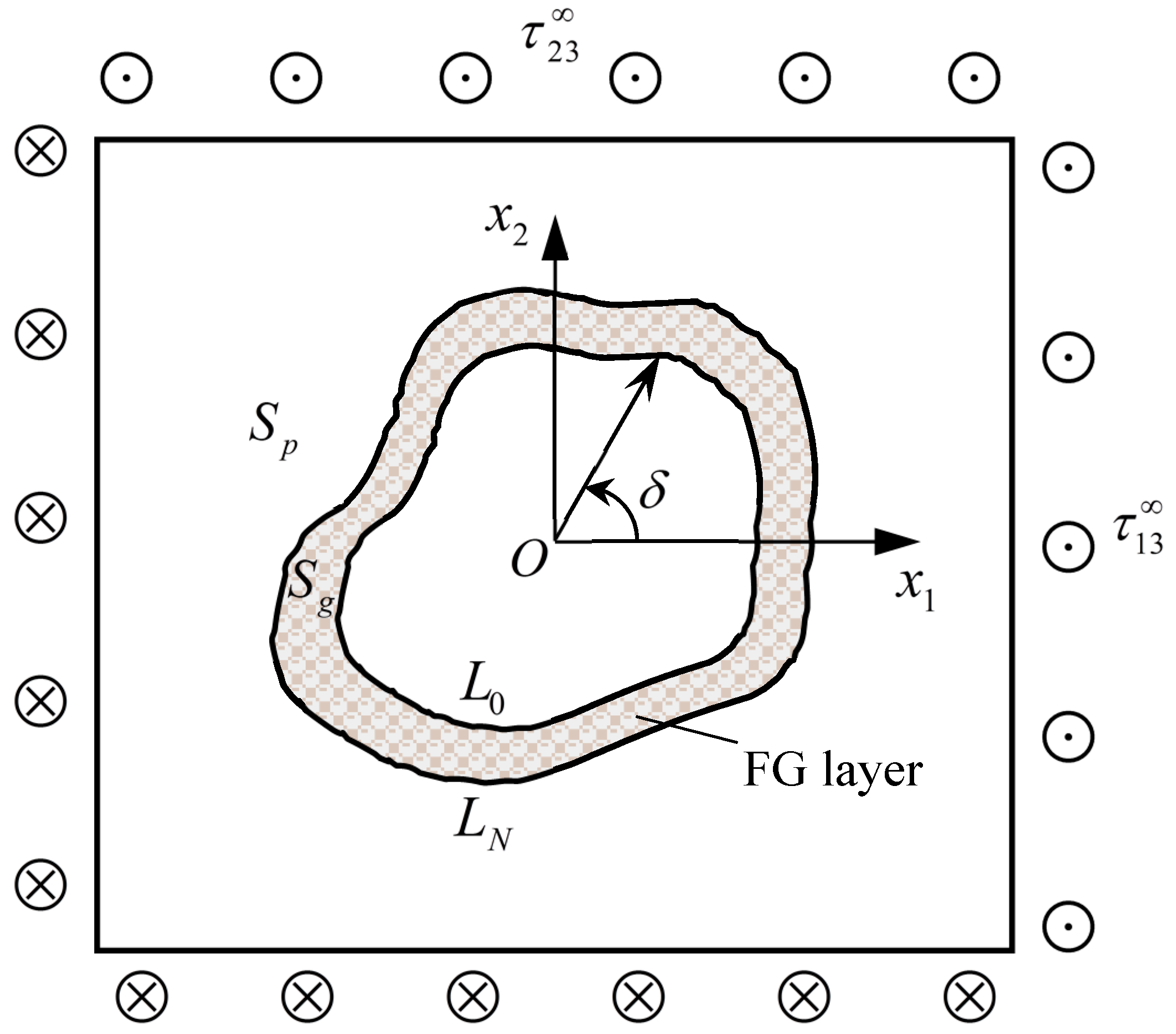
Figure 2.
The circumferential shear stresses around an elliptical hole without FG layer (comparison).
Figure 2.
The circumferential shear stresses around an elliptical hole without FG layer (comparison).
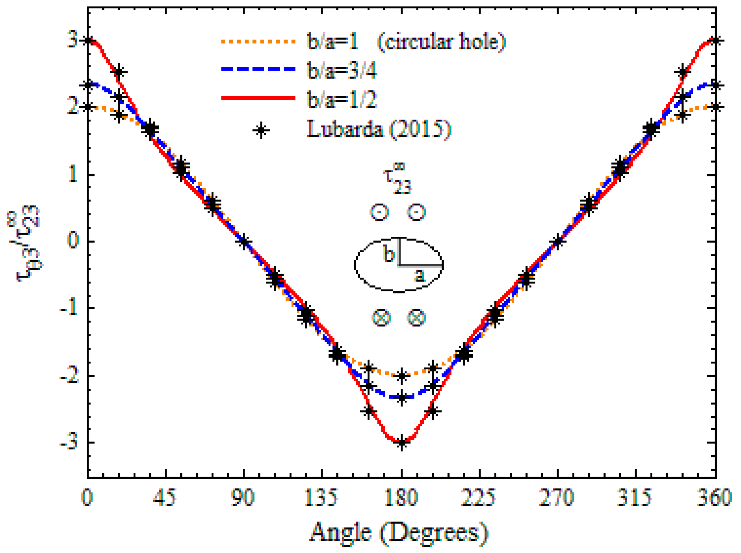
Figure 3.
The variation in shear stress around the hole (circle).
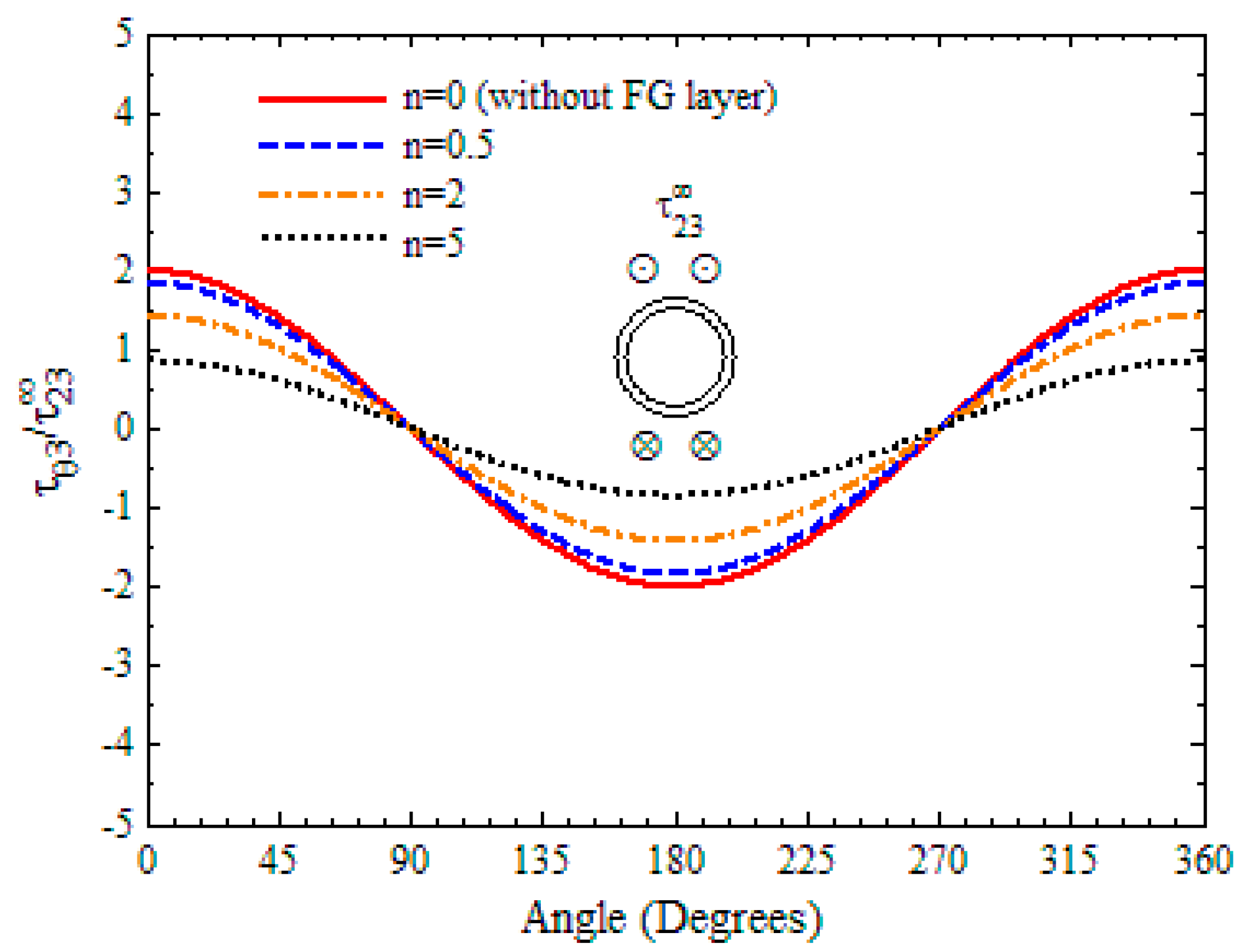
Figure 4.
The variation in shear stress around the hole (ellipse).

Figure 5.
The variation in shear stress around the hole (triangle).
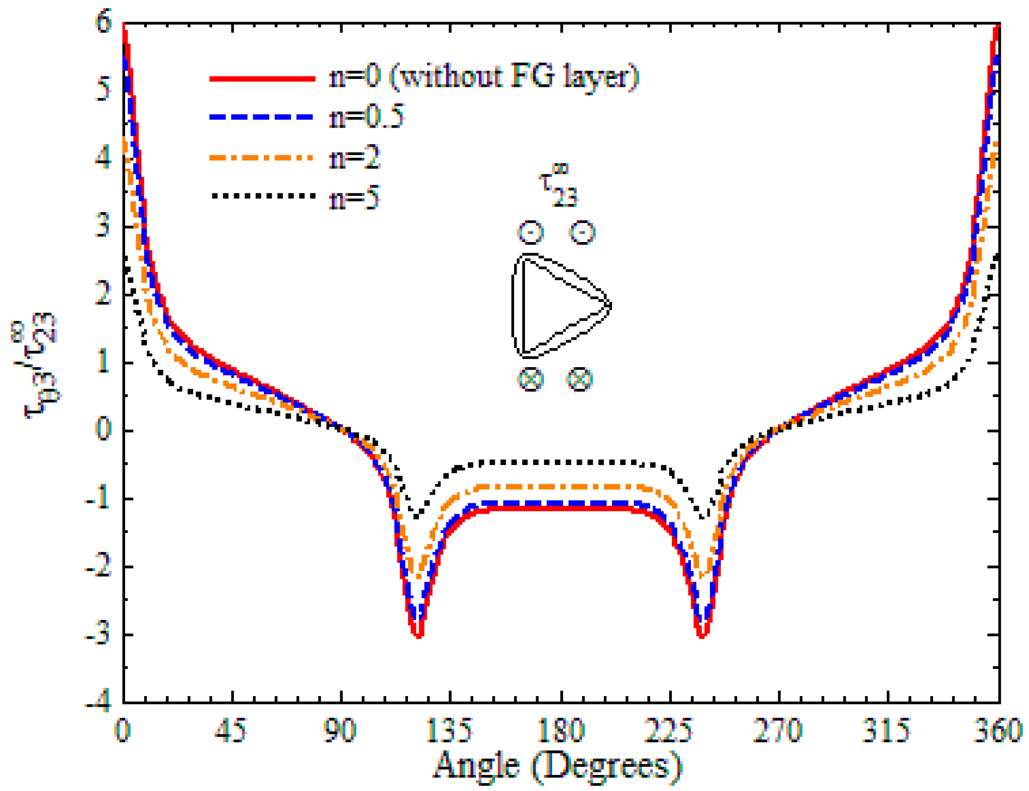
Figure 6.
The variation in shear stress around the hole (square).
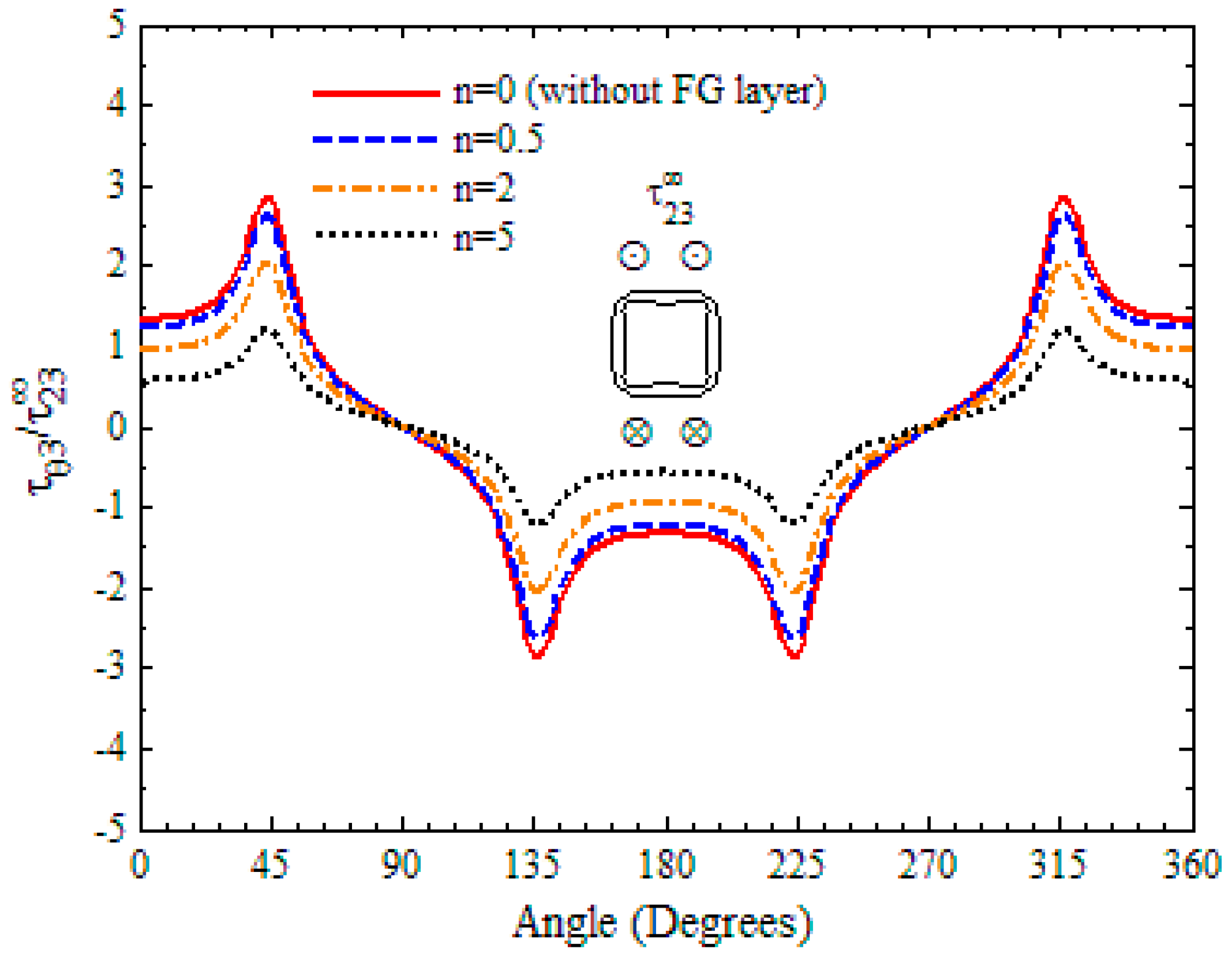
Figure 7.
The variation in shear stress around the hole (rectangle).
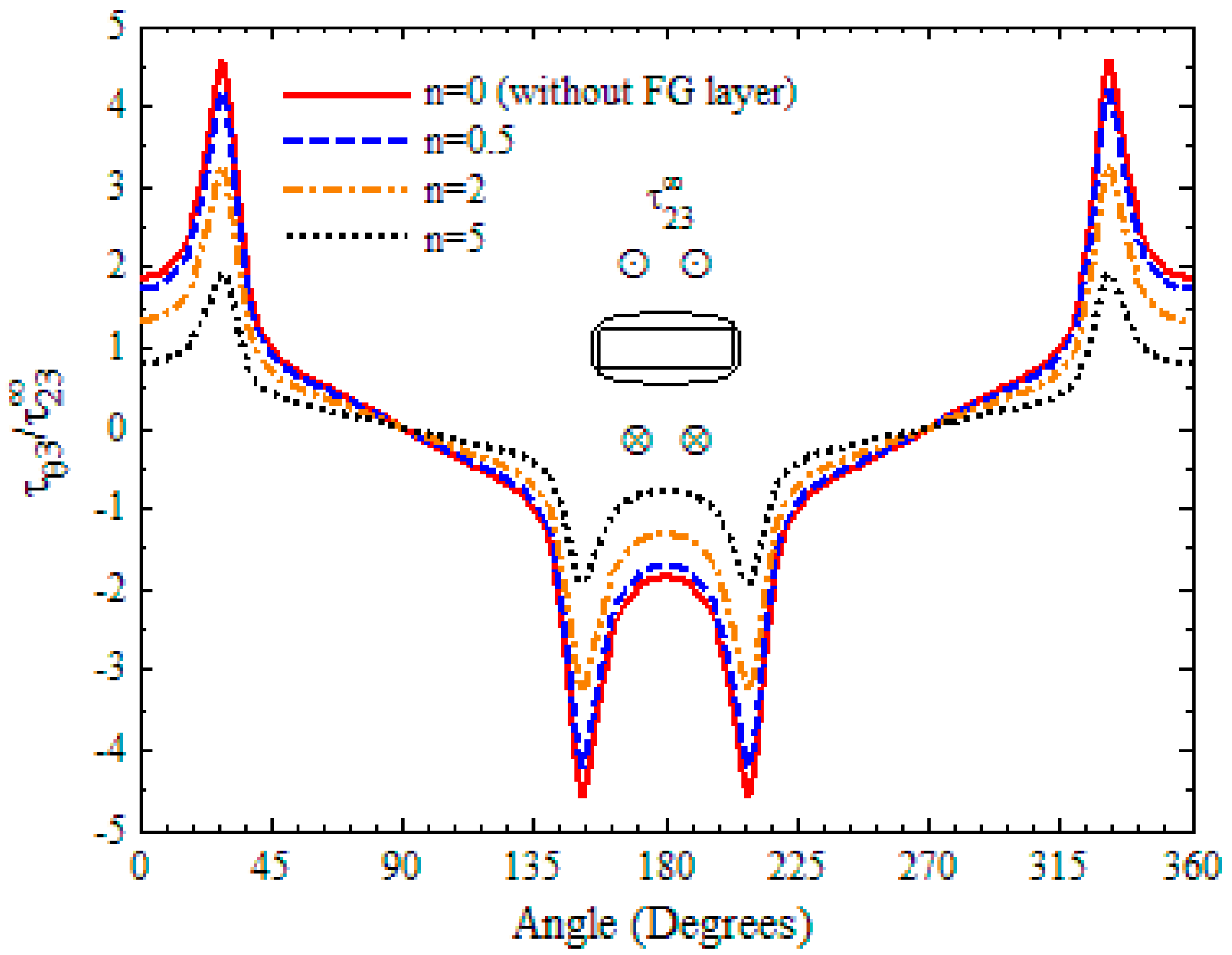
Figure 8.
The variation in shear stress along the normal direction of the hole (circle, ).
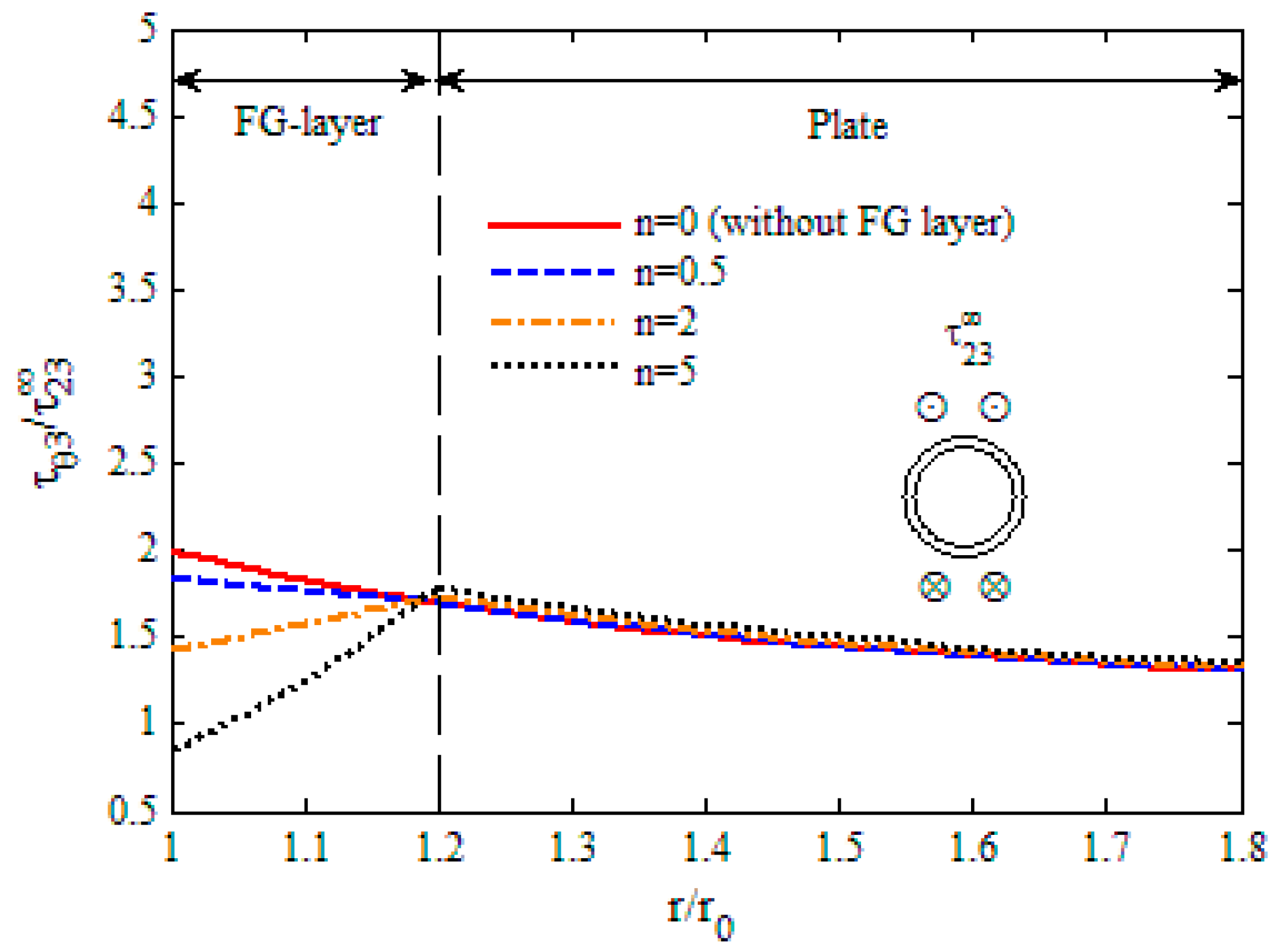
Figure 9.
The variation in shear stress along the normal direction of the hole (ellipse, ).
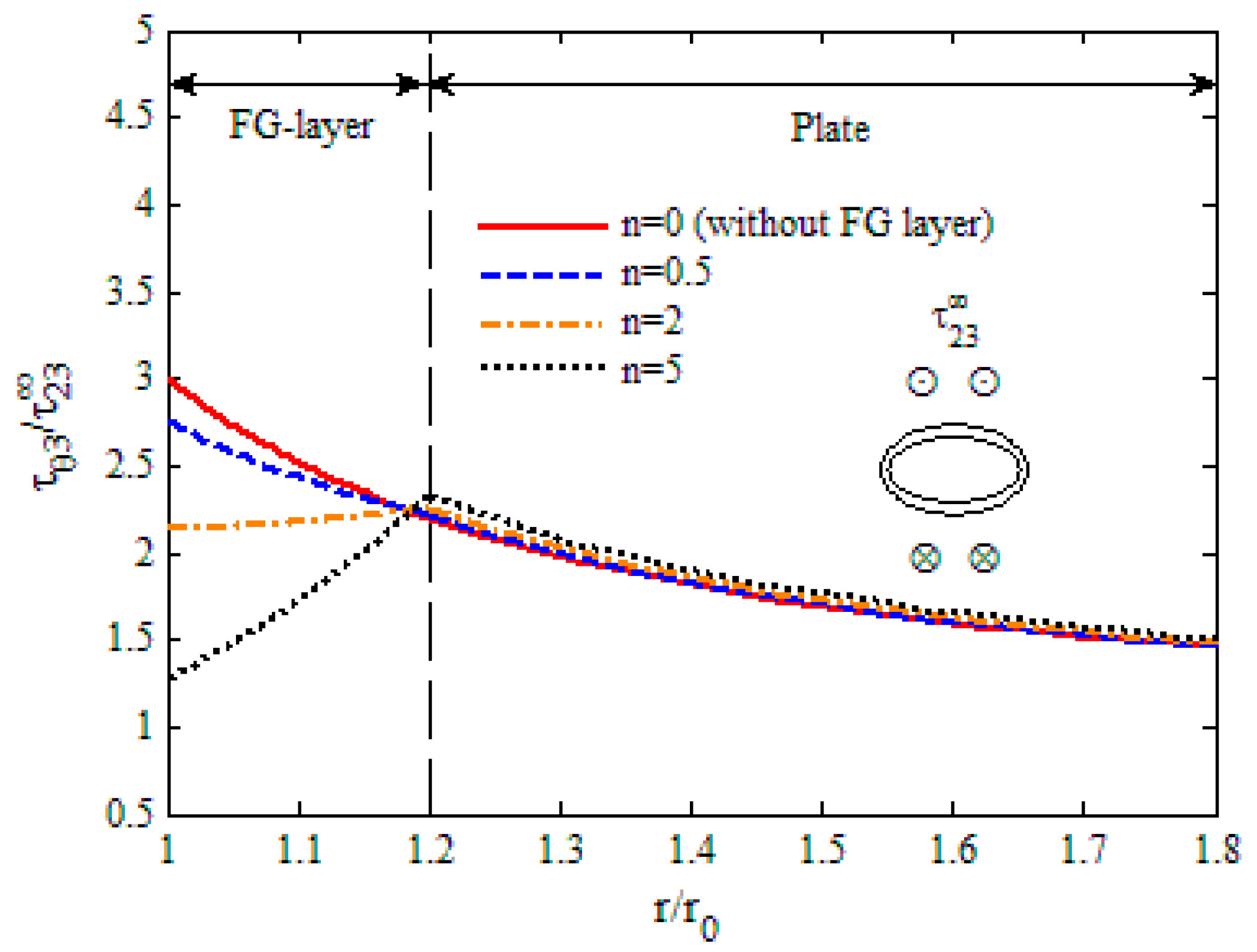
Figure 10.
The variation in shear stress along the normal direction of the hole (triangle, ).
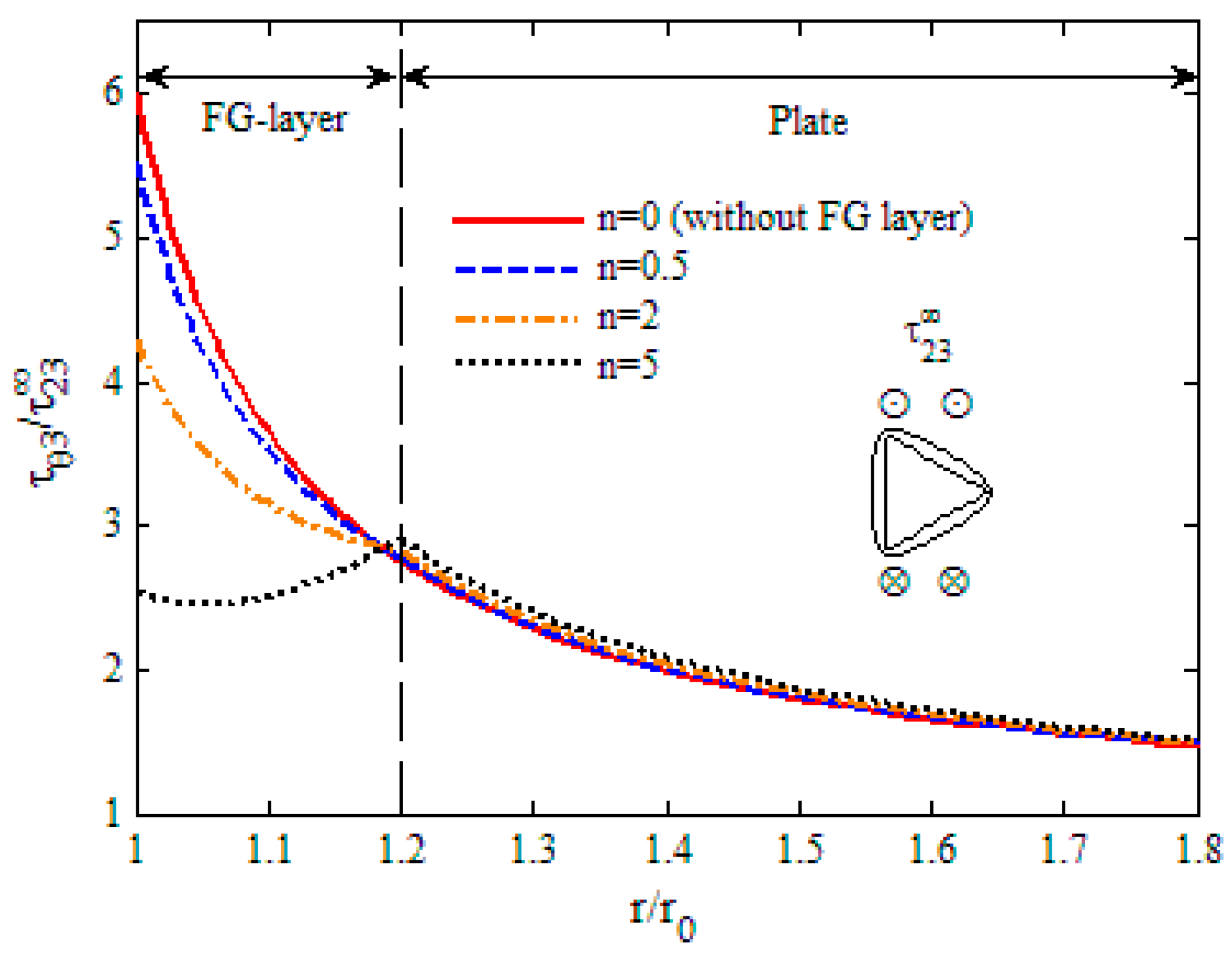
Figure 11.
The variation in shear stress along the normal direction of the hole (square, ).
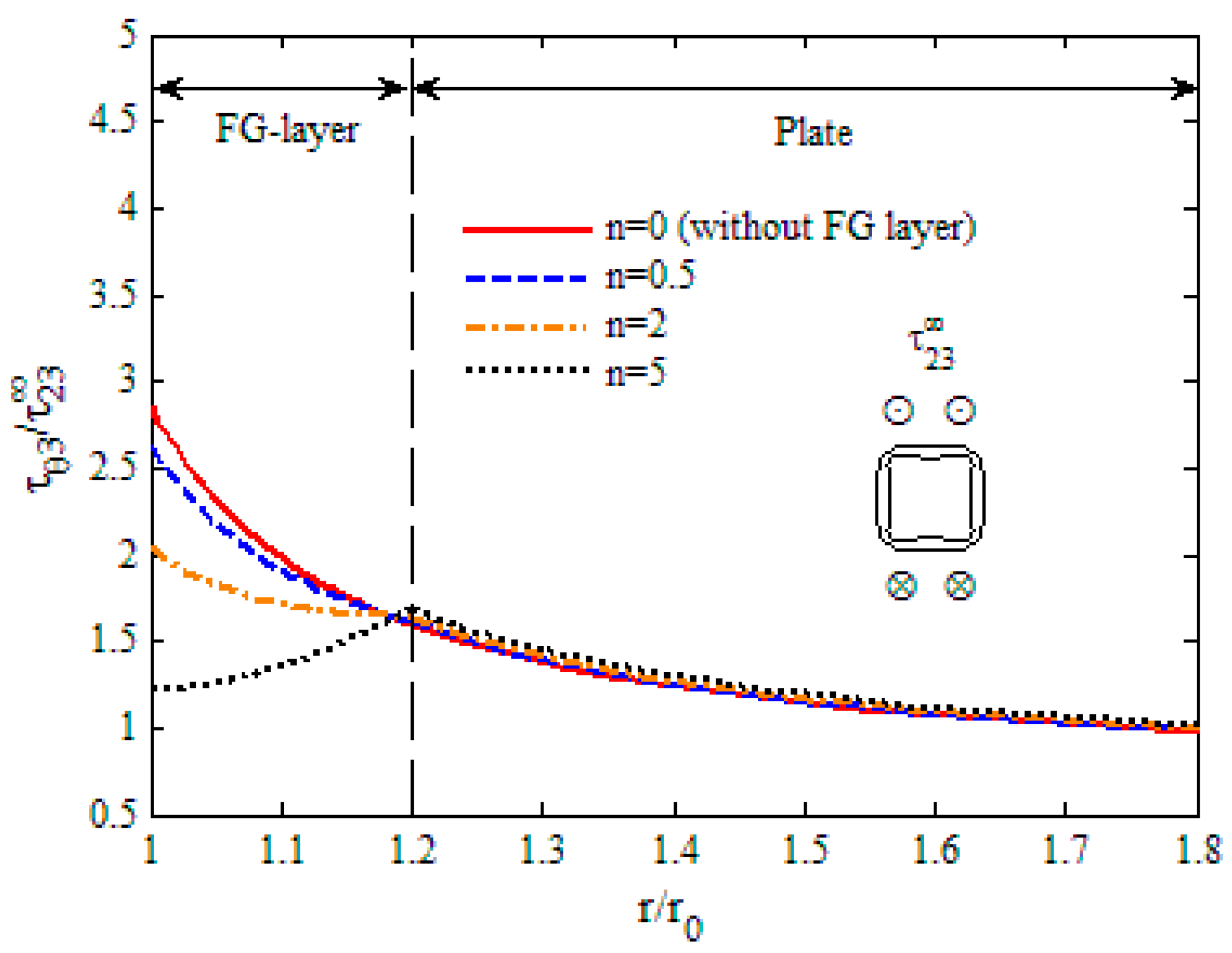
Figure 12.
The variation in shear stress along the normal direction of the hole (rectangle, ).
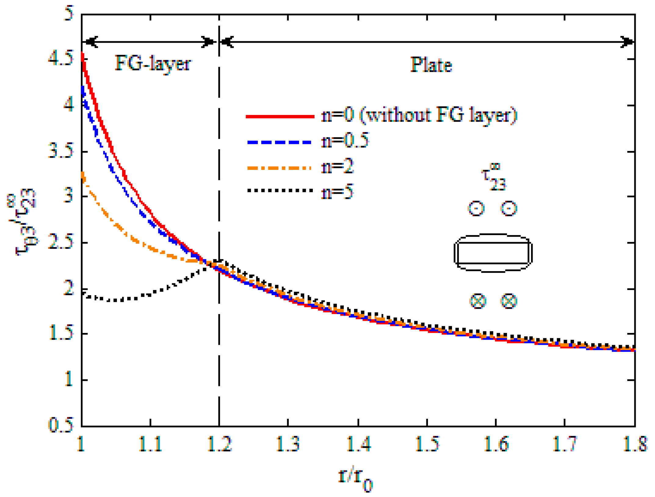
Figure 13.
The variation in SCF with exponent for different shaped holes.


Table 1.
The comparison of the stress concentration factor (SCF) for two different cases (with and without functionally graded (FG) layer).
Table 1.
The comparison of the stress concentration factor (SCF) for two different cases (with and without functionally graded (FG) layer).
| Shape of Hole | Without FG Layer | With FG Layer | The Decreasing Percentage of SCF | ||
|---|---|---|---|---|---|
| Exponent | SCF | Exponent | Minimum SCF | ||
| Circle | = 0 | 2.000 | = 0.932 | 1.716 | 14.2% |
| Ellipse | = 0 | 3.000 | = 1.695 | 2.255 | 24.8% |
| Triangle | = 0 | 6.000 | = 4.237 | 2.919 | 51.4% |
| Square | = 0 | 2.856 | = 3.220 | 1.663 | 41.8% |
| Rectangle | = 0 | 4.575 | = 4.068 | 2.299 | 49.7% |
© 2018 by the authors. Licensee MDPI, Basel, Switzerland. This article is an open access article distributed under the terms and conditions of the Creative Commons Attribution (CC BY) license (http://creativecommons.org/licenses/by/4.0/).
Share and Cite
MDPI and ACS Style
Guan, Y.; Li, Y. Stress Concentration and Optimized Analysis of an Arbitrarily Shaped Hole with a Graded Layer under Anti-Plane Shear. Appl. Sci. 2018, 8, 2619. https://doi.org/10.3390/app8122619
AMA Style
Guan Y, Li Y. Stress Concentration and Optimized Analysis of an Arbitrarily Shaped Hole with a Graded Layer under Anti-Plane Shear. Applied Sciences. 2018; 8(12):2619. https://doi.org/10.3390/app8122619
Chicago/Turabian StyleGuan, Yonggang, and Yun Li. 2018. "Stress Concentration and Optimized Analysis of an Arbitrarily Shaped Hole with a Graded Layer under Anti-Plane Shear" Applied Sciences 8, no. 12: 2619. https://doi.org/10.3390/app8122619
Note that from the first issue of 2016, this journal uses article numbers instead of page numbers. See further details here.