An Experimental Investigation on Bushing Geometrical Properties and Density in Thermal Frictional Drilling


1
Department of Mechanical Engineering, Faculty of Engineering and Architecture, Batman University, Batman 72100, Turkey
2
Department of Mechanical Engineering, Faculty of Technology, Firat University; Elazig 23000, Turkey
*
Author to whom correspondence should be addressed.
Appl. Sci. 2018, 8(12), 2658; https://doi.org/10.3390/app8122658
Submission received: 8 November 2018
/
Revised: 4 December 2018
/
Accepted: 13 December 2018
/
Published: 18 December 2018
(This article belongs to the Section Mechanical Engineering)
Abstract
:In thermal friction drilling (TFD) operations, the geometrical dimensions of bushing shape, height and wall thickness are the most vital consequences, since these increase the connecting length and strength. In this paper, AA7075-T651 aluminum alloys with 2, 4, 6, 8, and 10 mm thicknesses were drilled with the TFD process in order to investigate density, volume ratio, and height and wall thickness of the bushings. The experiments were conducted at constant spindle speed and feed rate conditions by using High Speed Steel (HSS) conical tools of 5, 10, 15, and 20 mm in diameter. It was experimentally found that the bushing height and the wall thickness had a tendency to increase linearly with the increase in both material thickness and tool diameter. The effect of tool diameter was found to have more influence on the measurable values than the thickness of the drilled material. The density of the bushing changed trivially. Approximately 70–75 percent of the evacuated material formed the bushing shape in TFD operations.
1. Introduction
Friction drilling is a hole production method, in which the metal cast sheet materials are drilled without cutting since a material sample heats up with the effect of the friction in the area of the conical tool and material contact. The generating temperature softens the sample, and then it is pushed downward by the tool, where the tool proceeds into the material to generate the bushing formation, increasing the connection strength in sheet materials. Therefore, investigation of the bushing formation is the main goal of TFD operations [1]. It is generally desired to obtain bushings only with a cylindrical shape, having no cracks and petal formations, in order to increase the connecting strength [2]. Higher bushing length leads to a greater screwing area as well as an increase in the connection strength of sheet materials [3]. Bushing shape, especially bushing height and wall thickness, depends on both the thickness of the drilled material (t) and the diameter of the hole (d), and hence it depends on the ratio of the drilled material and the diameter of the hole [4]. Bushing shape is completed in five steps and categorized according to the geometrical regions of the conical tool and proceeding dimension of the tool into the material [5]. The bushing height is measured to be approximately 2–3 times of the (t) [6].
A decrease in bushing height leads to an increase in the wall thickness of the bushing formation, which provides a greater screwing area by connecting sheet materials [7,8,9,10]. The height of the bushing depends on (d) rather than (t). The height of the bushing does not change with (t) for selecting constant hole diameters [11]. However, cracks and petal formations on the bushings cause the strength of the connections to decrease. Furthermore, deformation and fracture of the drilled material cause the occurrence of petal formation and cracks on bushing shape. Better selected tool geometry provides improved bushing formations [12].
During the TFD process, the bushing shape is formed with the help of the required temperature that occurs between the tool—workpiece interface owing to the friction. Due to this rise in temperature, the material thermally softens, and the yielding point decreases to facilitate plastic deformation to provide the bushing formation. The appropriate process temperature is generally between 1/2 and 2/3 of the melting temperature of the drilled material [13,14,15].
The main purpose of this paper is to investigate the effects of t and d on the geometrical dimensions of the bushing shape, such as bushing height and its wall thickness. Furthermore, the investigation of the proportion of the volume of the bushing shape to the total volume of the evacuated material is a crucial result. Therefore, this proportion was investigated experimentally in the TFD of the A7075-T651 aluminum alloy.
2. Materials and Methods
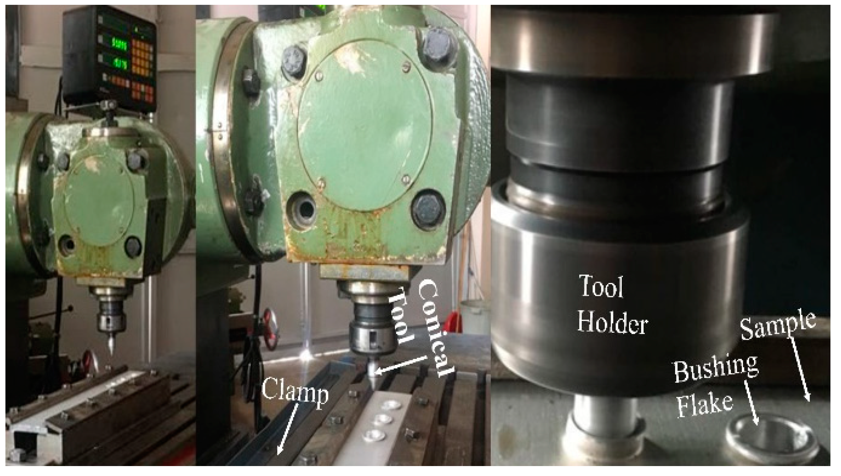
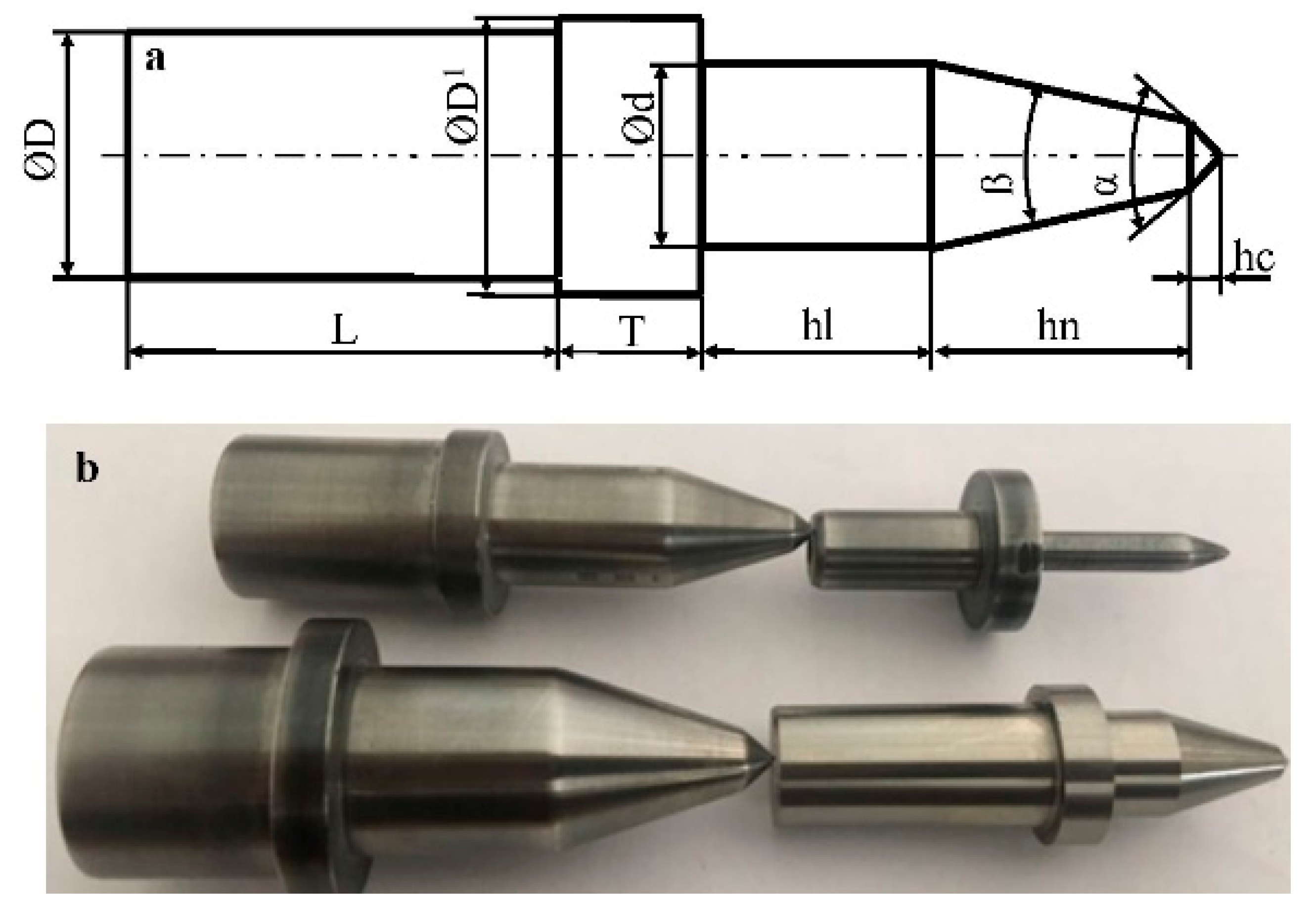
In the TFD experiments, a FU400 × 1600 V/2 model milling machine was employed. A7075-T651 aluminum alloy sheets 2, 4, 6, 8, and 10 mm thick were used as target materials. The experimental setup is shown in Figure 1. The thermal drilling conical tool and specimen fastening apparatus (a clamp), indicated by arrows with lines, can be clearly seen in Figure 1. The TFD tools were specially machined from HSS material with a 36° conical angle and 5, 10, 15, and 20 mm diameters. The geometrical dimensions of the conical tool used and its image are shown in Figure 2. The experiments were conducted at under constant 1120 rpm spindle speed and 25 mm/min feed rate conditions.
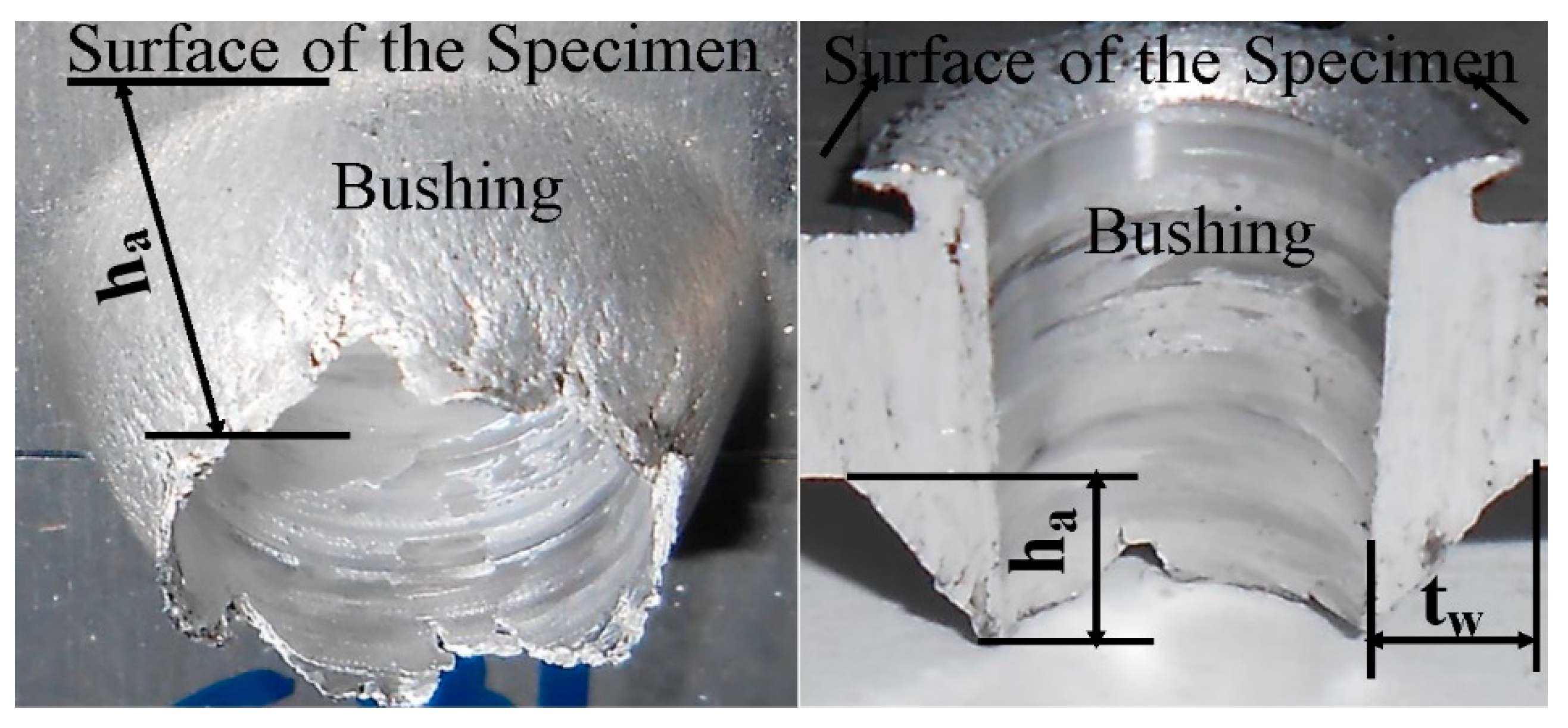
A depth micrometer gauge, with a sensitivity of 10−3 µm, was used in order to measure the heights of the bushings. Bushing height (ha) is a geometrical dimension measured from the subsurface of the thermal friction drilled material to the tip of the bushing formation as seen in Figure 3. Furthermore, the bushing wall thickness is a vital geometrical dimension, affecting the process consequences, such as connecting length and strength, with the help of threading. Also, the bushing wall thickness (tw) dimension is demonstrated in Figure 3. The outer diameter of the bushing dimensions was measured with a digital caliper gage with 0.02 mm precision. The bushing wall thickness values were calculated using Equation (1):
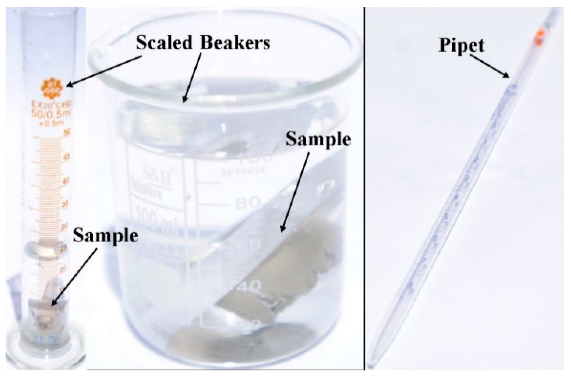
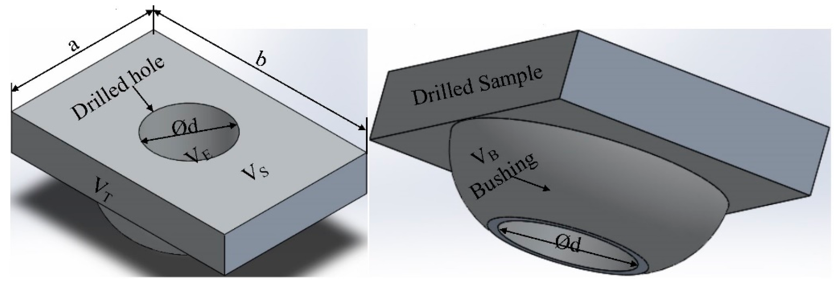
The drilled samples were divided into pieces, including the thermal friction drilled hole and bushing shape. The volume and weight of these pieces were measured separately, by using the scaled beaker and VIBRA AJ model digital scale with 0.01 g/cm3 accuracy, respectively. The volumetric measurement method of the divided samples is seen in Figure 4, in which beakers and water were used. In the measuring method, first, the beaker was filled up to the level of the integer number, and then the sample was placed in the beaker. The water, raised from the first level after the sample had been placed into the beaker, was aspirated with 0.1 g/cm3 accuracy by using a pipet until the level of the water decreased to the first level before the sample was placed into the beaker. The volume of the aspirated water by the pipet was accepted as the volume of the divided sample measurements. The weight of the divided samples was measured with a digital scale, having 0.01 g precision, as seen in Figure 5b. The density and the volumetric ratio of the bushing shapes were measured with the help of the measured weight and volume of the divided samples, including bushing, as shown in Figure 5. The volumes of the samples were measured by multiplying a, b, and t dimensions, which were measured on the samples by means of a digital caliper with 0.01 mm accuracy, subtracting the volume of thermal frictional drilled hole from the volume of the sample (VS), without including the volume of the bushing as demonstrated in Equation (2):
The weight of a sample (WS), without including the weight of the bushing shape (WB), was calculated by multiplying the volume of the sample with the density of the A7075-T651 aluminum alloy (ρ = 2.7 gr/cm3) as seen in Equation (3).
The weight of a divided sample (WS), without including the weight of the bushing shape, was calculated by the help of Equation (3). The total weight of a sample (WT), also including bushing weight, was measured by using a digital scale gauge as seen in Figure 5b.
The volume of the bushing shape was derived by subtracting the calculated volume of the sample (VS) from the measured total volume of the sample (VT) as shown in Equation (4):
The weight of the bushing shape can be derived by subtracting the weight of the sample, without including the bushing shape (WS), from the measured weight of the sample (WT) as seen in Equation (5):
The density of the bushing shape (ρB) was calculated by dividing the weight of the bushing (WB) by its volume (VB), as derived in Equation (2), as mentioned above.
3. Results and Discussion
3.1. Bushing Height and Wall Thickness
Bushing height and wall thickness values are crucial geometrical dimensions, affecting the outcomes of the TFD operations. While bushing height affects the connecting length and strength by means of achieving the numbers of the threading teeth, the depth of the threading tooth is affected by the bushing wall thickness. However, these dimensions have been barely investigated in the open literature. Nevertheless, in the literature, it is established that the bushing height is about 2–3 times the frictional thermal drilled material thickness. However, this idea may be valid for thin sheet metal materials, thinner than 2 mm, but it does not seem to be valid for sheet materials thicker than 2 mm.
In TFD operations, it is considered that the most influential parameter on bushing geometrical dimensions is material thickness. However, there are other crucial parameters, such as hole diameter, spindle speed, and feed rate, having a significant effect on these dimensions. It is because the volume of the evacuated material from the thermal frictional drilled material shapes the bushing. Therefore, the material thickness (t) and hole diameter (Ød) are more influential parameters than the selected spindle speed and feed rate, on the shaping of bushings. Although the effects of spindle speed and feed rate on the geometrical dimensions of the bushing shape are less than those of the material thickness and hole diameter, they may cause the generation of cracks and petal formation, especially in TFD of brittle sheet materials due to rotating and proceeding motions of the conical tool.
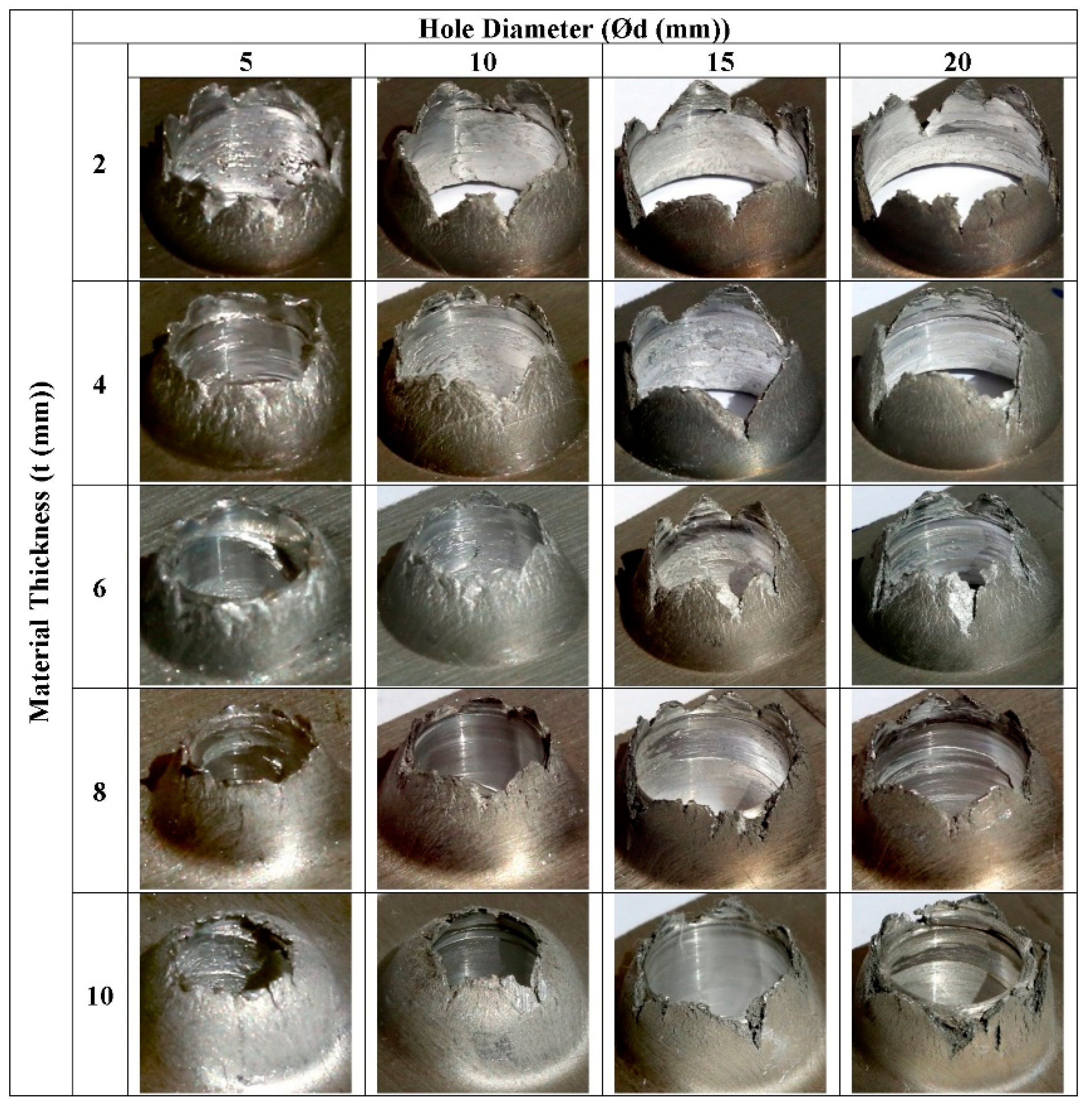
The experimentally gained bushing shapes for different t and d values are given in Figure 6. As shown, it can easily be seen that the cracks and petal formations on the bushings increased with higher d and lower (t) values. When the (t) value exceeded 6 mm, cracks and petal formations were almost completely eliminated under the experimental conditions; 4 and 6 mm material thicknesses were found to be appropriate only for hole diameters of 5 and 10 mm according to cracks and petal formation criteria, while 2 mm material thickness was not appropriate. Therefore, in the TFD of sheet materials, 2 mm in thickness, hole diameters, smaller than 5 mm, are not recommended to be selected.
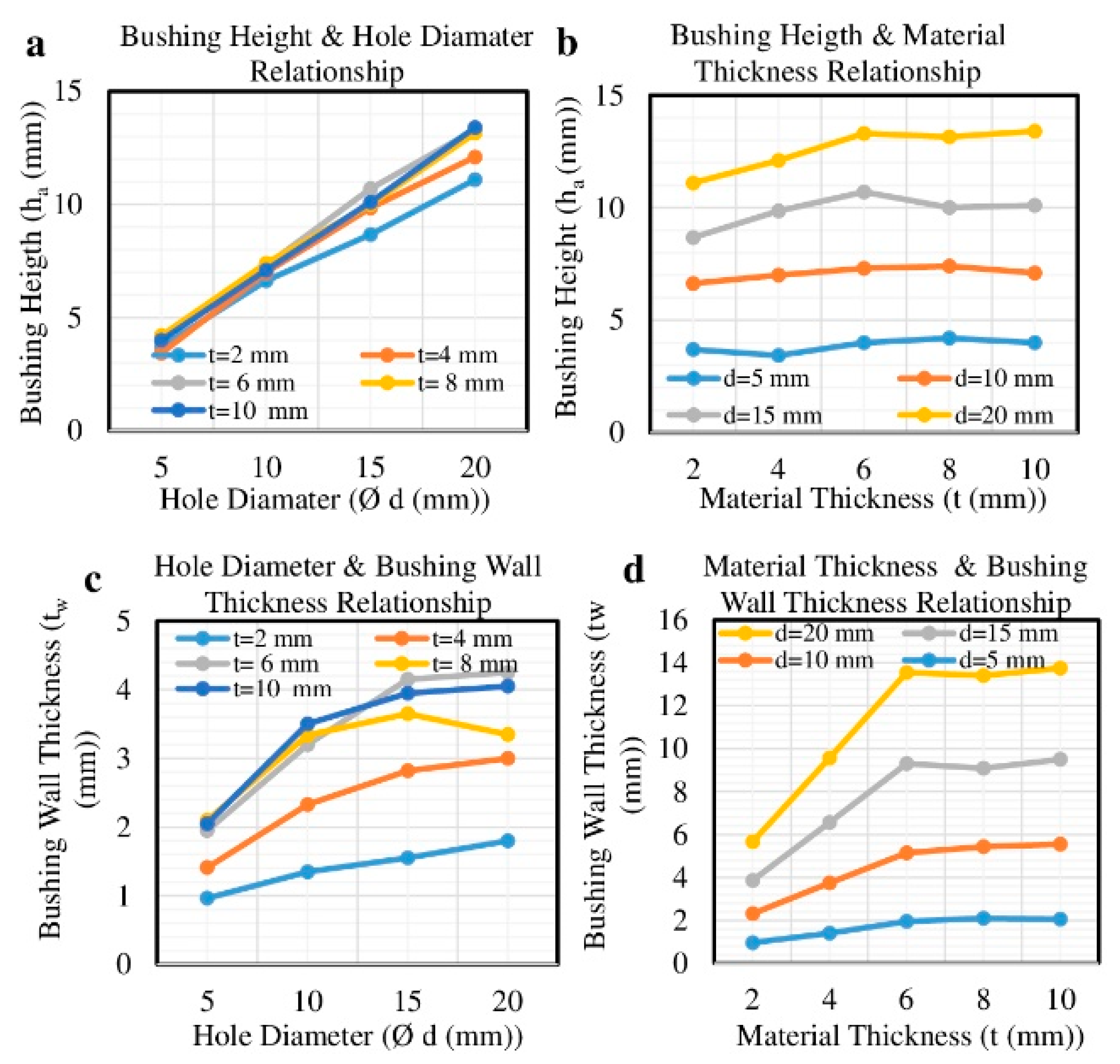
The effects of TFD parameters on the bushing height and wall thickness are given in Figure 7a,d. Figure 7a tells us the bushing height has a tendency to increase linearly with the hole diameter (d) for all values of material thickness. A negligible difference between 2 to 10 mm thicknesses was observed. However, the bushing wall thickness showed a nonlinear alteration with changing hole diameter from 5 mm to 20 mm, and material thickness from 2 mm to 10 mm, as demonstrated in Figure 7c,d. Bushing wall thickness values remained constant for material thicknesses greater than 6 mm for all hole diameters. However, it showed a linear change for 2, 4, and 6 mm thickness with selected 5, 10, and 15 mm hole diameters. Our findings are not in agreement with the literature, which states a 2–3 times relationship between the bushing height and the thickness of the material [3,4,5,6,13,14]. According to the graphs in Figure 7, the bushing height was linearly influenced by hole diameter, while the effect of material thickness did not have an important influence.
For the implemented experimental procedure, four kinds of hole diameters and five kinds of material thicknesses values were selected. Consequently, the recorded results for bushing height (ha) and bushing wall thickness (tw) depended on material thickness (t) and hole diameter (d). The experiments were performed in full factorial form, as demonstrated in Table 1.
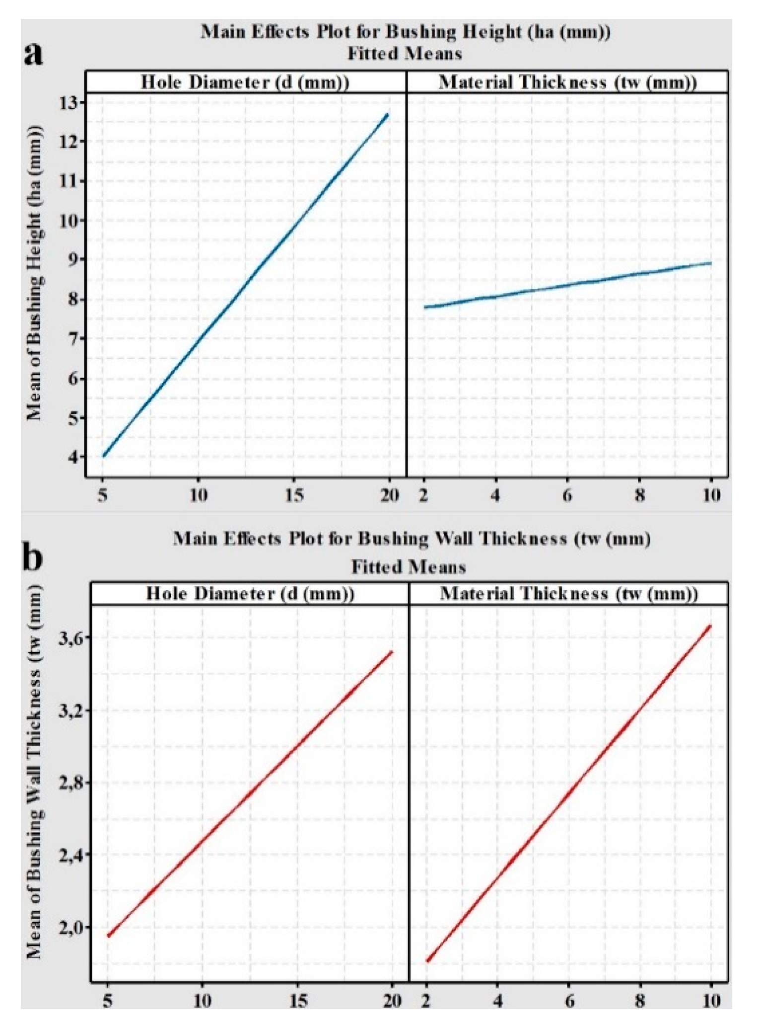
The MINITAB R15 package software was also used to plot the effects of factors on the bushing height and wall thickness. The main effect plots are given in Figure 8a–d. Surprisingly, contrary to literature, the effect of material thickness on the bushing height was less than the effect of hole diameter. However, the wall thickness of the bushing shape decreased gradually in the direction of tool movement from up to down.
3.2. The Density and the Volume Ratio of the Bushing
The quality of the TFD process depends on the ratio of the bushing volume (VB) to the ejected material (VE). The higher this ratio, the better the quality bushing shape without cracks and petal formation. Higher VB values indicate less material flowed and dissipated around the hole to form the bushing.
Figure 9 shows the effects of d, t and ρ values on the VB and VE in the TFD process. As clearly seen from the figure, almost no change (from 2.54 to 2.75) was observed in bushing density under the applied conditions. If we identify the ratio of VB to VE as R, the value of R can be written as in Equation (6).
The change in the R ratio was between 61–84%. The interaction effects of factors on R and ρ are given in Figure 10 and Figure 11. For 2 mm material thickness, the R values decreased with hole diameter but increased for materials thicker than 4 mm. Lower R values were also more pronounced at higher t values (t > 4 mm). According to these results, d and t values should be selected to be smaller than 10 mm and 4 mm, respectively.
4. Conclusions
The bushing shape, especially the softened flowed material, composing the bushing shape, was affected by material thickness and hole diameter, together with tool geometrical dimensions, feed rate and spindle speed. The spindle speed and feed rate provide the rotating and proceeding motions of the tool during the process, causing cracks and petal formation on the bushing shape. However, material thickness and hole diameter were crucial parameters, composing the bushing shape and its geometrical dimensions.
Summarizing the main results of the study, the following conclusions can be drawn:
- The bushing height and wall thickness values increased linearly with increases in both the (t) and (d) values. The effect of d was higher than the (t) values. Contrary to the literature, the bushing height values were not equal to approximately 2–3 times the TFD material thickness.
- The change in the density of the bushing was small. The recorded bushing density values were changed in the range of 2.54–2.75 gr/cm3.
- The ratio of the volume of the bushing (VB) to the volume of the evacuated material (VE), (R) values ranged between 61–84%. According to the recorded values, the volume of the ratio (R) was approximately 70%, i.e., between 70%–75%.
Author Contributions
All authors provided individual contributions during the research, analysis, investigation, and preparation procedure of the paper.
Funding
This research received no external funding.
Acknowledgments
This paper was not supported by anyone except the authors.
Conflicts of Interest
The authors declare no conflict of interest.
References
- Eliseev, A.A.; Fortuna, S.V.; Kolubaev, E.A.; Kalashnikova, T.A. Microstructure modification of 2024 aluminum alloy produced by friction drilling. Mater. Sci. Eng. 2017, 691, 121–125. [Google Scholar] [CrossRef]
- Demir, Z.; Özek, C. Investigate the effect of pre-drilling in friction drilling of A7075-T651. Mater. Manuf. Proc. 2014, 29, 593–599. [Google Scholar] [CrossRef]
- El-Bahloul, S.A.; El-Shourbagy, H.E.; El-Bahloul, A.M.; El-Midany, T.T. Experimental and thermo-mechanical modeling optimization of thermal friction drilling for AISI 304 Stainless steel. CIRP J. Manuf. Sci. Technol. 2018, 20, 84–92. [Google Scholar] [CrossRef]
- Van Geffen, J.A. Rotatable Piercing Tools for Forming Bossed Holes. U.S. Patent 4,185,486, 29 January 1980. [Google Scholar]
- Miller, S.F.; Li, R.; Wang, H.; Shih, A.J. Experimental and numerical analysis of the friction drilling process. J. Manuf. Sci. Eng. 2006, 128, 802–810. [Google Scholar] [CrossRef]
- Lee, S.M.; Chow, H.M.; Huang, F.Y.; Yan, B.H. Friction drilling of austenitic stainless steel by uncoated and PVD AlCrN- and TiAlN-coated tungsten carbide tools. Int. J. Mach. Tools Manuf. 2009, 49, 81–88. [Google Scholar] [CrossRef]
- Özek, C.; Demir, Z. Investigate the Surface Roughness and Bushing Shape in Friction Drilling of A7075-T651 and St 37 Steel. TEM J. 2013, 2, 170–180. [Google Scholar]
- Demir, Z.; Özek, C. Investigation of the bushing height and wall thickness in friction drilling of A7075-t651 alloy with and without hole. In Proceedings of the 5. National Machining and Manufacturing Symposium, Bursa, Turkey, 2014; pp. 23–25. [Google Scholar]
- Özek, C.; Demir, Z. Investigate of the effect of experimental parameters on the friction drilling of a7075-t651 aluminum alloy. Firat Univ. J. Eng. 2013, 25, 39–47. [Google Scholar]
- Kaya, M.T.; Aktas, A.; Beylergil, B.; Akyildiz, H.K. An experimental study on friction drilling of st12 steel. Trans. Can. Soc. Mech. Eng. 2014, 38, 319–329. [Google Scholar] [CrossRef]
- Özek, C.; Demir, Z. Bushing height according to material thickness. Dicle Univ. J. Eng. 2013, 4, 61–67. [Google Scholar]
- Raju, B.P.; Swamy, M.K. Finite element simulation of a friction drilling process using deform 3D. Int. J. Eng. Res. Appl. (IJERA) 2012, 2, 716–721. [Google Scholar]
- Ku, W.L.; Hung, C.L.; Lee, S.M.; Chow, H.M. Optimization in thermal friction drilling for SUS 304 stainless steel. Int. J. Adv. Manuf. Technol. 2011, 53, 935–944. [Google Scholar] [CrossRef]
- Miller, S.F.; Tao, J.; Shih, A.J. Friction drilling of cast metals. Int. J. Mach. Tools Manuf. 2006, 46, 1526–1535. [Google Scholar] [CrossRef]
- Miller, S.F.; Blau, P.T.; Shih, A.J. Microstructural alterations associated with friction drilling of steel, aluminum, and titanium. J. Mater. Eng. Perform. 2007, 14, 647–653. [Google Scholar] [CrossRef]
Figure 1.
Experimental setup with conical tool and fastening apparatus.

Figure 2.
Conical tools: (a) geometrical dimensions of tools (b) photos of tools.

Figure 3.
Bushing height on the bushing shape.

Figure 4.
Beakers, pipet, and samples, whose volumes were measured.

Figure 5.
Geometrical properties of samples.

Figure 6.
Bushing shape according to material thickness and hole diameter.

Figure 7.
The effects of hole diameter and material thickness on (a,b) bushing height, (c) and (d) bushing wall.
Figure 7.
The effects of hole diameter and material thickness on (a,b) bushing height, (c) and (d) bushing wall.

Figure 8.
The effects of hole diameter and material thickness on the mean of (a) the bushing height, (b) bushing wall thickness.
Figure 8.
The effects of hole diameter and material thickness on the mean of (a) the bushing height, (b) bushing wall thickness.

Figure 9.
The effects of hole diameter and material thickness on mean bushing height and bushing wall.
Figure 9.
The effects of hole diameter and material thickness on mean bushing height and bushing wall.

Figure 10.
The interaction plot of the hole diameter and volume ratio of the bushing.

Figure 11.
The interaction plot of the hole diameter and density of the bushing.


Table 1.
The full factorial design of the selected parameters.
| Material Thickness (tw (mm)) | Hole Diameter (d (mm)) | Bushing Height (ha (mm)) | Bushing Wall Thickness (tw (mm) |
|---|---|---|---|
| 2 | 5 | 3.70 | 0.965 |
| 2 | 10 | 6.63 | 1.350 |
| 2 | 15 | 8.67 | 1.550 |
| 2 | 20 | 11.10 | 1.800 |
| 4 | 5 | 3.43 | 1.410 |
| 4 | 10 | 7.00 | 2.330 |
| 4 | 15 | 9.85 | 2.815 |
| 4 | 20 | 12.10 | 3.000 |
| 6 | 5 | 4.00 | 1.950 |
| 6 | 10 | 7.30 | 3.200 |
| 6 | 15 | 10.70 | 4.150 |
| 6 | 20 | 13.30 | 4.250 |
| 8 | 5 | 4.20 | 2.100 |
| 8 | 10 | 7.40 | 3.340 |
| 8 | 15 | 10 | 3.650 |
| 8 | 20 | 13.15 | 3.350 |
| 10 | 5 | 4 | 2.050 |
| 10 | 10 | 7.10 | 3.500 |
| 10 | 15 | 10.10 | 3.950 |
| 10 | 20 | 13.40 | 4.050 |
© 2018 by the authors. Licensee MDPI, Basel, Switzerland. This article is an open access article distributed under the terms and conditions of the Creative Commons Attribution (CC BY) license (http://creativecommons.org/licenses/by/4.0/).
Share and Cite
MDPI and ACS Style
Demir, Z.; Özek, C.; Bal, M. An Experimental Investigation on Bushing Geometrical Properties and Density in Thermal Frictional Drilling. Appl. Sci. 2018, 8, 2658. https://doi.org/10.3390/app8122658
AMA Style
Demir Z, Özek C, Bal M. An Experimental Investigation on Bushing Geometrical Properties and Density in Thermal Frictional Drilling. Applied Sciences. 2018; 8(12):2658. https://doi.org/10.3390/app8122658
Chicago/Turabian StyleDemir, Zülküf, Cebeli Özek, and Muhammed Bal. 2018. "An Experimental Investigation on Bushing Geometrical Properties and Density in Thermal Frictional Drilling" Applied Sciences 8, no. 12: 2658. https://doi.org/10.3390/app8122658
Note that from the first issue of 2016, this journal uses article numbers instead of page numbers. See further details here.