Article

A Full-Process Numerical Analyzing Method of Low-Velocity Impact Damage and Residual Strength for Stitched Composites

Key Laboratory of Aero-engine Thermal Environment and Structure, Ministry of Industry and Information Technology, Jiangsu Province Key Laboratory of Aerospace Power System, State Key Laboratory of Mechanics and Control of Mechanical Structures, College of Energy & Power Engineering, Nanjing University of Aeronautics and Astronautics, Nanjing 210016, China
*
Author to whom correspondence should be addressed.
Appl. Sci. 2018, 8(12), 2698; https://doi.org/10.3390/app8122698
Submission received: 10 October 2018 / Revised: 5 December 2018 / Accepted: 14 December 2018 / Published: 19 December 2018
(This article belongs to the Special Issue Damage Inspection of Composite Structures)

Abstract

:

Featured Application

The full-process analyzing method for low-velocity impact damage and residual strength proposed in this paper can be used to simulate the failure and residual strength after low-velocity impact of stitched composites.

Abstract

The failure and residual strength after low-velocity impact of stitched composites are very important in their service and maintenance phases. In order to capture the failure and residual strength more accurately, a full-process numerical analyzing method was developed in this paper. The full-process numerical analyzing method includes two parts: (1) Part 1 is the progressive low-velocity impact damage prediction method for stitched composites; (2) Part 2 is the progressive residual strength prediction method by introducing all types of damage that are caused by the low-velocity impact as the analysis presuppositions. Subsequently, the failure and residual strength of G0827/QY9512 stitched composites were simulated by the full-process numerical analyzing method. When compared with experiments, it is found that: (1) the maximum error of low-velocity impact damage areas was 17.8%, and their damage modes were similar; (2) the maximum error of residual strength was 8.9%. At last, the influence rules of stitched density and stitching thread thickness were analyzed. The simulation results showed that, if there is no suture breakage failure, stitched density affects the mechanical properties of the stitched composites, while stitching thread thickness has little effect on it; otherwise, both factors have a significant effect on the mechanical properties.

1. Introduction

Stitched composites, which can be fabricated by inserting high-strength threads in through thickness direction into the preforms prior to resin consolidation process, have been widely used in various engineering fields, especially in aerospace, marine, motor sport, military, and specialist construction, due to their excellent impact resistance and compression-after impact strength [1]. By now, there is a great deal of studies that are related to the mechanical properties of stitched composites, which are fundamentally important in design phases. Heß proposed a finite element based unit cell model to simulate the in-plane and out-of-plane properties of the stitched composite laminates [2,3]. Two modes of fracture toughness of laminates stitched with a one-sided stitching technique were plain experimentally studied [4]. Yudhanto experimentally studied the damage mechanisms of the stitched composites, which include tensile and compressive properties [1,5,6]. Vallons investigated the influence of the stitching pattern on the mechanical properties of glass fiber non-crimp fabric composites [7].
During their service, it is common that the stitched composite structures subjected to multiple forms of low-velocity impact loading conditions, such as objects falling down on composites and a flying fragment with low-velocity impact on composites, which will result in the immeasurable impact damage inside the material and reduce its service safety. Therefore, the failure and residual strength after low-velocity impact of stitched composites are very important in their service and maintenance phases.
During the past several years, there are many studies on the response behavior of the stitched composites that suffered low-velocity impact. Mei analyzed the effects of stitched density on low-velocity impact damage of cross-woven carbon fiber reinforced silicon carbide composites (two-dimensional (2D) C/SiCs) [8]. Ravandi explored the effects of through-the-thickness on the Mode I inter-laminar fracture toughness and the performance of low-velocity of flax/epoxy composite laminates [9,10,11]. Lascoup studied the impact response of the three-dimensional (3D) stitched sandwich composite [12]. Tan studied the impact damage and subsequent damage propagation problems, and the effects of stitch density and stitch thread thickness of the stitched composites [13,14,15,16,17]. Mao experimentally investigated the stitched laminates that were subjected to low-velocity impact and the consequent compression behaviors [18]. Aktaş studied the impact and post impact behavior of stitched woven–knit hybrid composites by experiments [19]. Francesconi used a Finite Element model that was based on the use of progressive damage schemes to simulate the effect of stitching on the delamination resistance of laminated composites subjected to low-velocity impact [20]. Mao proposed a 3D dynamic finite-element model to simulate the damage development process and the influence factors of stitched laminates that were subjected to low-velocity impact [21]. However, the studies on the residual strength after low-velocity impact of stitched composites are still immature. Normally, there are three main equivalent methods used to predict the residual strength after low-velocity impact of composites. The first equivalent method is the softening inclusion method [22], in which the impact damage is equivalent to softening inclusion before the analysis of residual strength. The second equivalent method is the sub-layer buckling method [23], in which the impact damage is treated as the buckling of multiple sub-layers before the analysis of residual strength. The third equivalent method is the opening equivalence method [24], in which the impact damage is equivalent to the elliptical orifice panel before the analysis of residual strength. The above three equivalent methods are used widely due to their simplexes. However, due to the equivalent damage based on simplified hypothesis being different from the actual damage type and the damage degree of the composite structure after impact, the accuracy of the residual strength prediction model is affected. In this paper, a full-process analyzing method for low-velocity impact damage and residual strength was proposed and used to simulate the failure and residual strength after low-velocity impact of stitched composites.
The remainder of this paper can be summarized, as follows. In Section 2, a full-process numerical analyzing method for low-velocity impact damage and residual strength of stitched composites was developed in detail. In Section 3, the full-process numerical analyzing method was used to simulate the failure and residual strength after low-velocity impact at the different impact energy of G0827/QY9512 stitched composites. In Section 4, the effects of stitched density and stitching thread thickness were discussed. In Section 5, some key conclusions of this work were summarized.

2. Development of Full-Process Numerical Analyzing Method

In this section, a full-process numerical analyzing method was established, which took the actual damage situation of the composite structure after impact directly as a prerequisite for predicting the residual strength after impact. Consequently, this method not only avoided the measurement of impact-induced damage states but it also improved the accuracy of the residual strength prediction. The full-process numerical analyzing method includes two parts: (1) Part 1 is the progressive low-velocity impact damage prediction method for stitched composites; (2) Part 2 is the progressive residual strength prediction method by introducing all types of damage caused by the low-velocity impact as the analysis presuppositions.

2.1. Development of the Progressive Low-Velocity Impact Damage Prediction Method

2.1.1. Transient Stress Analysis

Figure 1 shows the transient analysis model of laminate and punch. At the t moment, the equilibrium equation can be deduced as:
σ i j , j t = ρ t u ¨ i + μ t u ˙ i
where, ρ t and μ t are the density and dynamic friction coefficient of laminate at t moment, respectively. u ˙ i and u ¨ i are the first and second derivative of the displacement to the time respectively.
At this moment, boundary conditions of the load are:
( σ i j t ) n j T ¯ i t = 0 ( o n   S σ )
where, S σ represents the stress boundary.
The equivalent integration of the equilibrium equation and the load boundary condition can be expressed, as follows:
V δ u i ( σ i j , j t ρ t u ¨ i μ t u ˙ i ) d V S σ δ u i ( ( σ i j t ) n j T ¯ i t ) d S = 0
As there will be geometric nonlinearity during the deformation of composites under the low-velocity impact load, strain tensor at t moment can be expressed, as follows:
ε i j t = B i j U j t = 1 2 ( u i , j t + u j , i t + u k , i t u k , j t ) ( i , j , k = x , y , z )
Decompose the above equation into linear and nonlinear terms
ε = ε L + ε N L
There is the following relationship of σ i j t and ε k l t at t moment.
σ i j t = Q ¯ i j k l t Δ t ε k l t
where Q ¯ i j k l t Δ t represents material elasticity matrix at t Δ t moment, and it can be obtained by coordinate transformation.
[ Q ¯ i j k l t Δ t ] = [ T ] [ Q t Δ t ] [ T ] T
Figure 2 shows the included angle θ between the direction of fiber and the global coordinate system, the transition matrix [ T ] can be expressed, as follows:
T = [ cos 2 θ sin 2 θ 0 0 0 2 sin θ cos θ sin 2 θ cos 2 θ 0 0 0 2 sin θ cos θ 0 0 1 0 0 0 0 0 0 cos θ sin θ 0 0 0 0 sin θ cos θ 0 sin θ cos θ sin θ cos θ 0 0 0 cos 2 θ sin 2 θ ]
According to Equations (3) and (6), the stress equilibrium equation at each moment can finally be deduced as:
V ( δ ε i j Q ¯ i j k l t Δ t ε k l + δ u i ρ t u ¨ i + δ u i μ t u ˙ i ) d V + V n 1 σ i j n 1 δ ( Δ η i j ) d V = S σ T ¯ i n δ u i d S
where, T ¯ i t and T ¯ i n are the surface force at t moment and n-th step in numerical analysis respectively; δ ε i j represents the strain at t moment; and, Δ η i j is the nonlinear term of strain increment.
Equation (9) can be solved by finite element method (FEM). It should be noted that when damage occurs, the stiffness matrix of the damaged area should be degraded and updated; the stress and strain fields will redistribute and need to be recalculated with an updated stiffness matrix.

2.1.2. Failure Criteria of Low-Velocity Impact

In the failure criteria of the elements, six damage modes were considered based on Modified Hou’s failure criteria [25,26], which are listed in Table 1.
Where σ i j is the stress component of the volume element in the principal direction; XT, YT, XC, and YC are the tensile and compressive strengths of the laminate in the longitudinal and transverse directions, respectively; Sf is the shear strength considering fiber failure; Sij is the shear strength in the principal direction of the laminate; σ 1 s t and X t s t are respectively the tensile stress and strength of the stitch; X T M and X C M are the tensile and compressive strength of matrix; and, S i j m is the shear strength of matrix.

2.1.3. Degradation Method of Material Performance of Impact Damage

After an impact failure occurs in a localized area of the laminate, the bearing capacity of the localized area will be decreased. As an important part of progressive damage analysis, the specific of partial degradation is to update the material stiffness matrices of the elements according to the types of failure. According to the References [21,25,27], the material property degradation rules with regard to different failure modes during the impact numerical analysis process are assumed, as follows:
(1) Fiber tension failure: all the material parameters are reduced to 0.07 of the original;
(2) Fiber compression failure: all the material parameters are reduced to 0.14 of the original;
(3) Matrix tension failure: E2, G12, G13 are reduced to 0.2 of the original;
(4) Matrix compression failure: E2, G12, G13 are reduced to 0.4 of the original;
(5) Delamination failure: E3, G12, G13, ν12, ν13 are reduced to 0.01 of the original; and,
(6) Suture breakage failure: The stiffness of the stitches degenerates to 100 Pa.
Where E2 and E3 are respectively transverse and normal tensile modulus; G12 and G13 are in-plane and out-plane shear modulus respectively; and, ν12 and ν13 are in-plane and out-plane Poisson’s ratio, respectively.
Different damage types are allowed to be coupled in the numerical calculation due to the coupling of it in the actual situation. If there are many kinds of damage in the numerical calculation, the material coefficient will be degraded correspondingly many times.

2.2. Development of the Progressive Residual Strength Prediction Method

2.2.1. Stress Analysis of Composite of Residual Strength

Consider the composite laminates have been loaded incrementally up to the nth step. By only considering thermal stress and external load, the equilibrium equation at the current load p n can be expressed, as follows:
σ i j , j n = 0   ( i , j = 1 , 2 , 3 ;   in   V n 1 )
The force boundary condition can be written, as follows:
( σ i j , j n ) n j n T ¯ i n = 0 ( on   S σ )
According to the incremental virtual displacement principle, transforming the Equations (10) and (11) as
V n 1 σ i j n δ ( Δ ε i j )   d V S σ T ¯ i n δ ( Δ u i ) d S = 0
where σ i j n is mechanical stress in each material principal direction at step n, V n 1 is the configuration of the body at step n, and Δ ε i j and Δ u i are the increment of strain and displacement between the (n − 1)-th and n-th load step, respectively.
The total stresses σ i j n can be expressed by the sum of previous stresses and the stress tensor increments, as follows:
σ i j n = σ i j n 1 + Δ σ i j n
Substituting Equation (13) into Equation (12), the following expression can be obtained:
V n 1 Δ σ i j n δ ( Δ ε i j )   d V = S σ T ¯ i n δ ( Δ u i ) d S V n 1 σ i j n 1 δ ( Δ ε i j )   d V
Moreover, the increment of strain Δ ε i j in the loading process can be expressed as:
Δ ε i j = Δ e i j + Δ η i j ,
where Δ e i j and Δ η i j are the linear and quadratic term, respectively. Assuming that the increment of the external load is small enough, the stress-strain relationship between any two adjacent load steps can be considered linear, i.e.,
Δ σ i j n = Q i j l k n 1 Δ ε k l
where Q i j l k n 1 is the reduced material stiffness matrix element at step n − 1.
Subsequently, substituting Equations (15) and (16) into Equation (14) and omitting high-order items, one obtains
V n 1 Q i j l k n 1 Δ ε k l δ ( Δ e i j )   d V + V n 1 σ i j n 1 δ ( Δ η i j )   d V = S σ T ¯ i n δ ( Δ u i ) d S V n 1 σ i j n 1 δ ( Δ e i j )   d V
Since the material properties, Q i j l k n 1 , depend on the current stresses and strains, Equation (17) has to be solved by a finite element discrete method combined with the Newton–Raphson iteration scheme. It should be noted that when damage appears, the stiffness matrix of the damaged area should be degraded and updated; the stress and strain fields will redistribute and need to be recalculated with the updated stiffness matrix.

2.2.2. Failure Criteria of Residual Strength

The continuous increase of external load leads to gradual expansion of the initial damage, Hashin’s failure criteria [28] is used to determine different types of damage in this process, as shown in Table 2.
Where α is the contribution factor of shear stress in fiber failure mode, α ( 0 , 1 ) .

2.2.3. Degradation Method of Material Performance of Residual Strength

In the numerical analysis of residual strength, the mechanical properties of failure elements will be degraded, which corresponds to the decrease of the bearing capacity of the laminate in the actual situation. According to the Reference [29], the material property degradation rules with regard to different failure modes during the residual strength numerical analysis process are assumed, as follows:
(1) Fiber tension failure: all the material parameters are reduced to 0.002 of the original;
(2) Fiber compression failure: all the material parameters are reduced to 0.002 of the original;
(3) Matrix tension failure: E2 is reduced to 0.2 of the original;
(4) Matrix compression failure: E2 is reduced to 0.008 of the original;
(5) Delamination failure: E3, G12, G13, ν12, ν13 are reduced to 0; and,
(6) Suture breakage failure: The stiffness of the stitches degenerates to 100 Pa.
The ultimate failure criterion of composite laminates used in this paper is: when the fiber failure extends perpendicularly to the load direction to the boundary of the laminate, it is considered that the whole panel is destroyed.

2.3. Analysis Procedure of Impact Damage and Residual Strength

Based on stress analysis of composite laminate, failure criteria, and the stiffness degradation model, combined with the finite element method, an integrated finite element model is developed to simulate low-velocity impact damage and to predict the residual strength of stitched composite laminates. Figure 3 shows the simulation procedure in detail. In order to conduct failure analysis based on an element-by-element scheme, the constitutive equations formulated and the failure criteria and the degradation model were implemented with APDL language.

3. Application of Full-Process Analyzing Method

In this section, the full-process numerical analyzing method was applied to simulate the failure and residual strength of G0827/QY9512 stitched composites presented in Reference [18], which was stitched with Kevlar29 (1500 deniers) and formed by the resin film infusion (RFI) molding process. The mechanical properties of G0827/QY9512 are listed in Table 3. Modified lock stitches were used in the 60 mm × 40 mm laminate with stacking sequence of [45/0/-45/90]4s. In Reference [18], the low-velocity impact resistance and the residual strength of G0827/QY9512 stitched composites were studied experimentally.

3.1. Numerical Simulations of Low-Velocity Impact Behavior

3.1.1. Finite Element Model and Boundary Conditions

Figure 4 shows the finite element model of the composite laminate with a stitched density of 5 mm × 5 mm. In this model, element LINK167 was selected to establish the elements of stitching threads, element SOLID164 was selected to establish the elements of composite laminates and interfaces. The thickness of interfaces was only one-tenth of the layers to the laminate, which was about 0.0167 mm. The total number of elements was 81,018. The properties of interface elements were the same as the actual laminate elements, but the interface elements were only used to judge the delamination damage. Moreover, rigid-body balls were used to simulate experimental punch and counterweights. The type of contact between the punch and the stitched laminate was defined as ASTS, namely the automatic face-to-face contact. The degree of freedom of the joints around the laminate should be limited.

3.1.2. Numerical Simulation Results

Table 4 shows the numerical simulation results and the errors of the damage projection areas between experiments [18] and simulation results after the impact energies of 11.0 J, 16.8 J, 23.4 J. As seen from Table 4, the maximum error is 17.8%. Figure 5 shows the progressive damage process of the laminate and the projection diagrams of experimental and simulation damage after the impact of 16.8 J. As can be seen from it, at 0.1 ms, the punch contacted the laminate, but the laminate was not damaged; at 0.2 ms, the upper layers of the laminate were damaged by the mode of the delamination failure (DF); at 0.4 ms, the fiber compression failure (FCF) was found on the center of the laminate; at 0.6 ms, the fiber tension failure (FTF) was found at lower layers of the laminate for the first time; at 0.8 ms, the FTF and FCF were extended, but the DF was not extended; at 1.1 ms, the damage inside the laminate no longer expanded with the time increase, and the damage area reached the maximum. The damage modes from the center to the outside are orderly FTF, FCF, and DF. The images that were obtained by the experiment are similar to the impact damage results that were obtained by the simulation. Therefore, the simulation results are consistent with the experimental results, which prove the rationality of the full-process analyzing method that was developed in this paper.
Throughout the process of impact, Figure 6 shows the final failure of each layer. When the punch impacts the laminate, the laminate undergoes concave deformation, which results in the compressive phenomenon in the upper layers and the tensile phenomenon in the lower layers. Therefore, on the upper layers of the laminate, the damage modes are mainly the FCF and MCF, but on the lower layers of the laminate, the damage modes are mainly the FTF and matrix tension failure (MTF). Figure 7 shows the final failure of each interface. The DF is found in every interface of the laminate. From the view of the damage area of the DF, the distribution of the area shows the shape of a Pyramid, namely, from the upper layers of the laminate to the lower layers, the damage areas of the DF are changed from small to large, which means that the effect of compressive stress is greater than that of tensile stress. Moreover, the SBF cannot be found in the whole process of the impact.

3.2. Numerical Simulations of Residual Strength

3.2.1. Finite Element Model and Boundary Conditions

Figure 8 shows the finite element model of the stitched laminate for the analysis of residual strength. In this model, element LINK180 was selected to establish the elements of stitching threads and element SOLID185 was selected to establish the elements of composite laminates and interfaces. The total number of elements was 81,081. Moreover, the impact damage results were imported into the model as its initial conditions. The compressive load is applied to the model as an initial load of 180 MPa with an increase of 5 MPa for each step. If there is any damage, then the corresponding load will be maintained and the degradation of stiffness matrix will be executed for 20 cycles. If there is no damage, the load will continue to increase until the damage extends to the boundary of the laminate.

3.2.2. Numerical Simulation Results

Table 5 shows the comparisons of residual strengths between experiments [18] and numerical simulation results after the impacts of 11.0 J, 16.8 J, and 23.4 J. The maximum error for residual strength between experiment and simulation is 8.9%, which indicates the accuracy of the simulation results and the rationality of the full-process analysis method for residual strength.
Figure 9 shows progressive damage process of the laminate after impact of 16.8 J. At 310 MPa, the damage modes of the FTF, FCF, and DF are found in the laminate. At 315 MPa, the FMSF and FCF extend to the boundary, leading to the final failure of the laminate.

4. Discussion

The parameters of stitched density and stitching thread thickness are two main factors affecting the mechanical behaviors of stitched composites. In this section, the influence rules of these parameters are discussed by simulations.

4.1. Effect of Stitched Density

In order to analyze the effect of stitched density on the failure and residual strengths of the laminates after impact, laminates with three stitched densities, namely 2 mm × 2 mm, 5 mm × 5 mm, and 10 mm × 10 mm (2 × 2, 5 × 5 and 10 × 10 laminates), and the stitching thread thickness of 1500d, were investigated after the impact of 10 J.
Figure 10 shows the full-processes of low-velocity impact damage and residual strength for stitched composite laminates with different stitched densities. In the simulation process of low-velocity impact damage, four kinds of damage modes, i.e., FTF, MTF, FCF, and DF, were found. The rules of the damage expansion are similar, e.g., the DF occurs firstly, then the FCF occurs and the FTF occurs at last. The impact time of the stitched (2 × 2, 5 × 5 and 10 × 10) composite laminates are 1.3 ms, 1.4 ms and 1.4 ms, respectively. This change of the impact time is mainly caused by the difference of stiffness between laminates that are associated with the different stitched densities. The initial impact damage of 2 × 2 laminate is slightly larger than others, which means that there is no obvious association between the initial impact damage and the final impact damage. Compared with the 10 × 10 laminate, the final impact damage areas for the 5 × 5 and 2 × 2 laminates are reduced by about 10% and 28.1%, respectively. However, no matter how large the stitched density is, the shapes of the final damaged areas are always the spindle-shaped.
In the simulation processes of residual strength, stitched density has a significant effect on the damage mode. The stitched composites with different stitched densities have different failure modes. For example, the FMSF and MCF are found in the 10 × 10 laminate, whereas the 2 × 2 and 5 × 5 laminates extend the damage with the FTF and FTF+FCF, respectively. Moreover, the greater the stitched density of the stitched composites, the less the damage mode and the smaller the damaged area are found in final damage, as shown in Figure 10. When compared with the 10 × 10 laminate, the final damage area of the 2 × 2 laminate is smaller, and only the FTF mode is found on its boundary, whereas the damage modes of the FTF, FCF, MTF, and FMSF are found on the boundary of the 10 × 10 laminate.
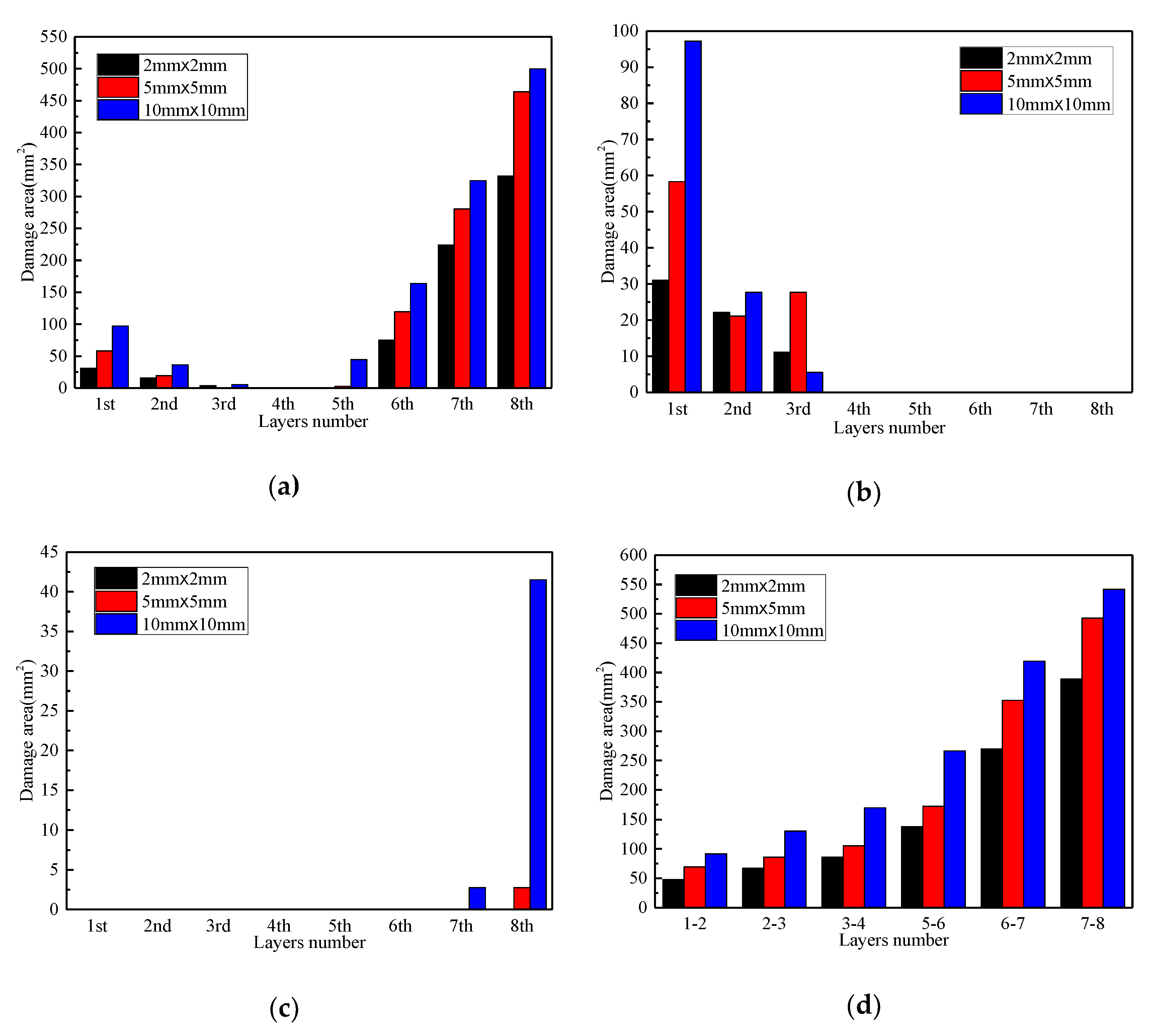
As shown in Figure 11, the damage area of the DF is the largest and the area of the FTF is the smallest. With the increase of the number of layers, the damage area of the MTF decreases firstly and then increases; and, the FCF occurs in the first four layers and the area of damage shows a tendency to decrease; the FTF only occurs in the 7th and 8th layers and is not found in the stitched (2 × 2) composites; the DF occurs in all layers and the damage area increases significantly. It also can be seen that, the greater the stitched density of the stitched composites, the less the damage mode, the smaller the damaged area, and the fewer the damaged layers after impact.
Figure 12 shows the predicted residual strengths of the laminates with three stitched densities. It is observed that stitched density has a significant effect on residual strength after impact. When compared with the 10 × 10 laminate, the residual strengths for the 5 × 5 and 2 × 2 laminates are increased by 20% and 30.9%, respectively. This means that the greater the stitched density of the stitched composites, the greater the residual strength. The experimental data of literature [30] further confirms this finding.

4.2. Effect of Stitching Thread Thickness

In order to analyze the effect of stitching thread thickness on failure and the residual strengths of the stitched composites after impact, the 5 × 5 laminates with three stitching thread thickness, namely 500d, 1500d and 3000d (500d, 1500d, and 3000d laminates), were investigated after the impact of 10 J.
Figure 13 shows the failure of stitching thread in stitched composites with three different stitching thread thicknesses after the impact of 10 J. It is observed that the SBF is only found in the 500d stitched composite, while no SBF occurred in the 1500d and 3000d stitched composites due to the maximum stresses of stitching elements being lower than the strength of the stitch.
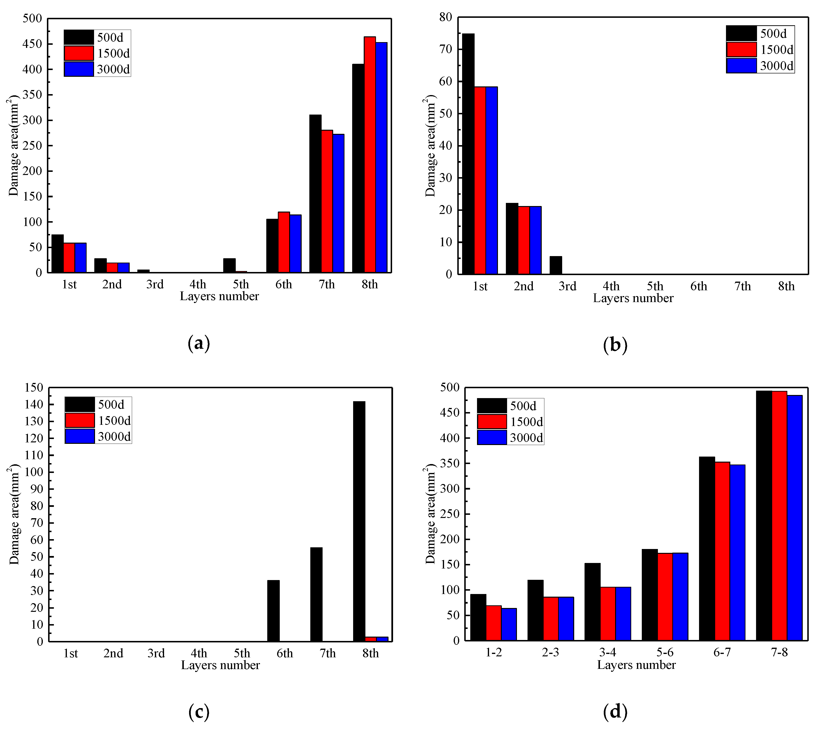
Figure 14 shows the progressive damage processes of stitched composite laminates with different stitching thread thicknesses after impact of 10 J. Due to the SBF occurring in the 500d laminate, its damage modes and damage area are significantly different from the 1500d and 3000d laminates. As shown in Figure 15, the final damage modes and damage areas of the 1500d and 3000d laminates are similar. However, the final damage area of the 500d laminate is far larger than the other two laminates and its final damage mode contains a large number of fiber failures (FTF + FCF), especially given that the FTF is much more serious than the other two. With the increase of the number of layers, the damage area of the MTF decreases firstly and then increases, the FCF occurs in the first three layers and the damage area decreases rapidly, the FTF only occurs in the 6th~8th layers and it is rarely found in the stitched (1500d and 3000d) composites, moreover, the damage area of the DF shows a significant increase.
Figure 16 shows the predicted residual strengths of the laminates with three stitching thread thicknesses. When compared with the 500d laminate, the residual strengths of the 1500d and 3000d laminates are increased by 43.5% and 47.8%, respectively. It indicates that the greater the stitching thread thickness of the stitched composites, the greater the residual strength. This is consistent with the conclusion of literature [30]. However, the gap between the 1500d and 3000d laminates is 3%. It means that if there is no SBF, the stitching thread thickness will have little effect on the residual strength, but if it does, there will be a significant effect, which is not reflected in the literature [30].

5. Conclusions

In this paper, a full-process numerical analyzing method for low-velocity impact damage and residual strength of stitched composites was proposed and used to simulate the failure and residual strength of stitched composites in Reference [18]. By using the full-process numerical analyzing method, the effects of stitched density and stitching thread thickness on the failure and residual strength of stitched composites were discussed. Some key conclusions of this work can be summarized, as follows:
(1) The maximum error of low-velocity impact damage areas between the numerical simulation results and experiments was 17.8%, and the damage projection diagrams between them were similar. The maximum error of residual strength after impact between the simulation results and experiments was 8.9%. Therefore, the full-process analyzing method that is developed in this paper is reasonable and effective.
(2) The greater the stitched density of the stitched composites, the less the damage mode, the smaller the damaged area, the fewer the damaged layers, and the higher the residual strength.
(3) If there is no SBF, then stitching thread thickness has little effect on the damage mode, damage area, and residual strength; but if it does, there is a significant effect. The mechanical properties of stitched composites without SBF are much better than those with SBF.

Author Contributions

H.Z., Y.X. and J.C. analyzed the data; H.Z. and M.W. wrote the paper; W.W. and H.C. contributed the analysis method.

Acknowledgments

This work has been supported by the Key Laboratory of Aero-engine Thermal Environment and Structure, Ministry of Industry and Information Technology (NO. XCA1700205).

Conflicts of Interest

The authors declare no conflict of interest.

Abbreviations and Nomenclature

ρ t the density of laminate at t moment
μ t the dynamic friction coefficient at t moment
u ˙ i the first derivative of the displacement to the time
u ¨ i the second derivative of the displacement to the time
σ i j t the stress at t moment
σ i j n 1 the stress in each material principal at (n − 1)th step
σ i j n the stress in each material principal direction at step n
S σ the stress boundary
T i t ¯ the surface force at t moment
T ¯ i n the surface force at n-th step in numerical analysis
δ ε i j the strain at t moment
Q ¯ i j k l t Δ t material elasticity matrix of the last moment which depends on the current stresses and strains
Δ η i j the nonlinear term of strain increment
p n the load at nth step
Δ ε i j strain increment between step n and step n − 1
Δ u i displacement increment between step n and step n − 1
Δ e i j the linear term of strain increment
V n 1 the configuration of the body at step n
Q i j l k n 1 the reduced material stiffness matrix element at step n − 1
XTthe tensile strength of the laminate in the longitudinal direction
XCthe compressive strength of the laminate in the longitudinal direction
YTthe tensile strength of the laminate in the transverse direction
YCthe compressive strength of the laminate in the transverse direction;
XTMthe tensile strength of matrix
XCMthe compressive strength of matrix
Sfthe shear strength considering fiber failure
Sijthe shear strength in the principal direction of the laminate
Sijmthe shear strength of matrix
σ 1 s t the tensile stress of the stitch
X t s t the tensile strength of the stitch
S i j m the shear strength of matrix
E2the transverse tensile modulus
E3the normal tensile modulus
G12the in-plane shear modulus
G13the out-plane shear modulus
ν12the in-plane Poisson’s ratio
ν13the out-plane Poisson’s ratio
FTFfiber tension failure
FCFfiber compression failure
MTFmatrix tension failure
MCFmatrix compression failure
DFdelamination failure
SBFsuture breakage failure
FMSFfiber-matrix shear failure
RFIresin film infusion

References

  1. Yudhantoa, A.; Watanabea, N.; Iwahorib, Y.; Hoshi, H. Compression properties and damage mechanisms of stitched carbon/epoxy composites. Compos. Sci. Technol. 2013, 86, 52–60. [Google Scholar] [CrossRef]
  2. Heß, H.; Himmel, N. Structurally stitched NCF CFRP laminates. Part 1: Experimental characterization of in-plane and out-of-plane properties. Compos. Sci. Technol. 2011, 71, 549–568. [Google Scholar] [CrossRef]
  3. Heß, H.; Himmel, N. Structurally stitched NCF CFRP laminates. Part 2: Finite element unit cell based prediction of in-plane strength. Compos. Sci. Technol. 2011, 71, 569–585. [Google Scholar] [CrossRef]
  4. Plain, K.P.; Tong, L. An experimental study on mode I and II fracture toughness of laminates stitched with a one-sided stitching technique. Compos. Part A: Appl. Sci. Manuf. 2011, 42, 203–210. [Google Scholar] [CrossRef]
  5. Yudhanto, A.; Watanabea, N.; Iwahorib, Y.; Hoshi, H. Effect of stitch density on tensile properties and damage mechanisms of stitched carbon/epoxy composites. Compos. Part B: Eng. 2013, 46, 151–165. [Google Scholar] [CrossRef]
  6. Yudhanto, A.; Lubineau, G.; Ventura, I.A.; Watanabe, N.; Iwahori, Y.; Hoshi, H. Damage characteristics in 3D stitched composites with various stitch parameters under in-plane tension. Part A: Appl. Sci. Manuf. 2015, 71, 17–31. [Google Scholar] [CrossRef]
  7. Vallons, K.; Adolphs, G.; Lucas, P.; Lomov, S.V.; Verpoest, I. The influence of the stitching pattern on the internal geometry, quasi-static and fatigue mechanical properties of glass fibre non-crimp fabric composites. Part A: Appl. Sci. Manuf. 2014, 56, 272–279. [Google Scholar] [CrossRef]
  8. Mei, H.; Yu, C.K.; Xu, H.R.; Cheng, L.F. The effects of stitched density on low-velocity impact damage of cross-woven carbon fiber reinforced silicon carbide composites. Ceram. Int. 2016, 42, 1762–1768. [Google Scholar] [CrossRef]
  9. Bensadoun, F.; Depuydt, D.; Baets, J.; Verpoest, I.; Van Vuure, A.W. Low velocity impact properties of flax composites. Compos. Struct. 2017, 176, 933–944. [Google Scholar] [CrossRef]
  10. Ravandi, M.; Teo, W.T.; Tran, L.Q.N.; Yong, M.S.; Tay, T.E. The effects of through-the-thickness stitching on the Mode I interlaminar fracture toughness of flax/epoxy composite laminates. Mater. Des. 2016, 109, 659–669. [Google Scholar] [CrossRef]
  11. Ravandi, M.; Teo, W.S.; Tran, L.Q.N.; Yong, M.S.; Tay, T.E. Low velocity impact performance of stitched flax/epoxy composite laminates. Compos. Part B: Eng. 2017, 117, 89–100. [Google Scholar] [CrossRef]
  12. Lascoup, B.; Aboura, Z.; Khellil, K.; Benzeggagh, M. Impact response of three-dimensional stitched sandwich composite. Compos. Struct. 2010, 92, 347–353. [Google Scholar] [CrossRef]
  13. Tan, K.T.; Watanabe, N.; Iwahori, Y. Finite element model for compression after impact behaviour of stitched composites. Compos. Part B: Eng. 2015, 79, 53–60. [Google Scholar] [CrossRef]
  14. Tan, K.T.; Watanabe, N.; Iwahori, Y. Effect of stitch density and stitch thread thickness on low-velocity impact damage of stitched composites. Compos. Part A: Appl. Sci. Manuf. 2010, 41, 1857–1868. [Google Scholar] [CrossRef]
  15. Tan, K.T.; Watanabe, N.; Iwahori, Y.; Ishikawa, T. Understanding effectiveness of stitching in suppression of impact damage: An empirical delamination reduction trend for stitched composites. Compos. Part A: Appl. Sci. Manuf. 2012, 43, 823–832. [Google Scholar] [CrossRef]
  16. Tan, K.T.; Yoshimura, A.; Watanabe, N.; Iwahori, Y.; Ishikawa, T. Further investigation of delamination reduction trend for stitched composites. Compos. Sci. Technol. 2015, 118, 141–153. [Google Scholar] [CrossRef]
  17. Tan, K.T.; Yoshimura, A.; Watanabe, N.; Iwahori, Y.; Ishikawa, T. Effect of stitch density and stitch thread thickness on damage progression and failure characteristics of stitched composites under out-of-plane loading. Compos. Sci. Technol. 2013, 74, 194–204. [Google Scholar] [CrossRef]
  18. Mao, C.J.; Xu, X.W.; Zheng, D. Experimental investigation of stitched laminates subjected to low-velocity impact and compression after impact. Acta Mater. Compos. Sin. 2012, 29, 160–166. [Google Scholar]
  19. Aktaş, A.; Aktaş, M.; Turan, F. Impact and post impact (CAI) behavior of stitched woven–knit hybrid composites. Compos. Struct. 2014, 116, 243–253. [Google Scholar] [CrossRef]
  20. Francesconi, L.; Aymerich, F. Numerical simulation of the effect of stitching on the delamination resistance of laminated composites subjected to low-velocity impact. Compos. Struct. 2017, 159, 110–120. [Google Scholar] [CrossRef]
  21. Mao, C.J.; Zhang, C. Numerical analysis of influence factors on low-velocity impact damage of stitched composite laminates. Mech. Adv. Mater. Struct. 2018, 1–10. [Google Scholar] [CrossRef]
  22. Xiong, Y.; Poon, C.; Straznicky, P.V.; Vietinghoff, H. A prediction method for the compressive strength of impact damaged composite laminates. Compos. Struct. 1995, 30, 357–367. [Google Scholar] [CrossRef]
  23. Caprino, G. Residual strength prediction of impacted CFRP laminates. J. Compos. Mater. 1984, 6, 508–518. [Google Scholar] [CrossRef]
  24. Chen, P.H.; Shen, Z.; Wang, J.Y. A new method for compression after impact strength prediction of composite laminates. J. Compos. Mater. 2002, 36, 589–610. [Google Scholar]
  25. Wen, W.D.; Xu, Y.; Cui, H.P. Damage analysis of laminated composites under low velocity impact loading. J. Mater. Eng. 2007, 7, 6–11. [Google Scholar]
  26. Weng, J.M.; Wen, W.D.; Xu, Y. Strength prediction of cruciform specimen under biaxial loading. Trans. Nanjing Univ. Aeronaut. Astronaut. 2017, 3, 286–295. [Google Scholar]
  27. Camanho, P.P.; Matthews, F.L. A progressive damage model for mechanically fastened joints in composite laminates. J. Compos. Mater. 1999, 33, 2248–2280. [Google Scholar] [CrossRef]
  28. Hashin, Z. Failure criteria for unidirectional fiber composites. J. Compos. Mater. 1980, 2, 329–335. [Google Scholar] [CrossRef]
  29. Weng, J.M.; Wen, W.D.; Zhang, H.J. Study on low-velocity impact and residual strength at high temperatures of composite laminates. Proc. Inst. Mech. Eng. Part G—J. Aerosp. Eng. 2017, 1–18. [Google Scholar] [CrossRef]
  30. Tan, K.T.; Watanabe, N.; Iwahori, Y.; Ishikawa, T. Effect of stitch density and stitch thread thickness on compression after impact strength and response of stitched composites. Compos. Sci. Technol. 2012, 72, 587–598. [Google Scholar] [CrossRef]
Figure 1. Transient analysis model of laminate and punch.
Applsci 08 02698 g001
Figure 2. Relationship between two coordinate systems.
Applsci 08 02698 g002
Figure 3. Simulation procedures of full-process analyzing method.
Applsci 08 02698 g003
Figure 4. Finite element model of the stitched laminate.
Applsci 08 02698 g004
Figure 5. Progressive damage process of the laminate and the damage projection diagrams obtained by experiment [18] and simulation after the impact of 16.8 J. Note: (1) DF: delamination failure; (2) FTF: fiber tensile failure; (3) FCF: fiber compressive failure; (4) MTF: matrix tensile failure; (5) MCF: matrix compressive failure; (6) FMSF: fiber-matrix shear failure; and, (7) SBF: suture breakage failure.
Applsci 08 02698 g005
Figure 6. Final failure of each layer after the impact of 16.8 J.
Applsci 08 02698 g006
Figure 7. Final failure of each interface after the impact of 16.8 J.
Applsci 08 02698 g007
Figure 8. Finite element model of the stitched laminate.
Applsci 08 02698 g008
Figure 9. Progressive damage process of the laminate after the impact of 16.8 J.
Applsci 08 02698 g009
Figure 10. Full-process of low-velocity impact damage and residual strength for laminates with different stitched densities.
Applsci 08 02698 g010
Figure 11. Distributions of different damage modes with different stitched densities after the low-velocity impact damage: (a) MTF; (b) FCF; (c) FTF; and, (d) DF.
Applsci 08 02698 g011
Figure 12. The predicted residual strengths with different stitched densities.
Applsci 08 02698 g012
Figure 13. SBF of the laminates after the impact of 10 J.
Applsci 08 02698 g013
Figure 14. Progressive damage processes of the laminates after the impact of 10 J.
Applsci 08 02698 g014
Figure 15. Distribution of different damage modes with different stitching thread thicknesses after the low-velocity impact damage: (a) MTF; (b) FCF; (c) FTF; and, (d) DF.
Applsci 08 02698 g015
Figure 16. The effect of stitching thread thickness on residual strength under the impact of 10 J.
Applsci 08 02698 g016
Table 1. Expression of six damage modes for low-velocity impact.
Damage ModesExpression
Fiber tension failure (FTF) ( σ 1 X T ) 2 + ( σ 12 S f ) 2 + ( σ 13 S f ) 2 1   ( σ 1 0 )
Fiber compression failure (FCF) ( σ 1 X C ) 2 + ( σ 12 S f ) 2 + ( σ 13 S f ) 2 1   ( σ 1 < 0 )
Matrix tension failure (MTF) ( σ 2 Y T ) 2 + ( σ 12 S 12 ) 2 + ( σ 23 S 23 ) 2 1   ( σ 2 > 0 )
Matrix compression failure (MCF) 1 4 ( σ 2 S 12 ) 2 + ( σ 12 S 12 ) 2 + Y C 2 σ 2 4 S 12 2 Y C σ 2 Y C 1   ( σ 2 < 0 )
Delamination failure (DF) { ( σ 1 + σ 2 + σ 3 X T M ) 2 + τ 12 2 S 12 m 2 + τ 13 2 S 13 m 2 + τ 23 2 S 23 m 2 1   ( σ 11 + σ 22 + σ 33 > 0 ) ( σ 1 + σ 2 + σ 3 X C M ) 2 + τ 12 2 S 12 m 2 + τ 13 2 S 13 m 2 + τ 23 2 S 23 m 2 1   ( σ 11 + σ 22 + σ 33 < 0 )
Suture breakage failure (SBF) ( σ 1 s t X t s t ) 2 1
Table 2. Expression of six damage modes for residual strength.
Damage ModesExpression
Fiber tension failure (FTF) ( σ 1 X T ) 2 + α ( σ 12 S 12 ) 2 + α ( σ 13 S 12 ) 2 1   ( σ 1 > 0 )
Fiber compression failure (FCF) ( σ 1 X C ) 2 1   ( σ 1 < 0 )
Matrix tension failure (MTF) ( σ 2 Y T ) 2 + α ( σ 12 S 12 ) 2 + ( σ 23 S 23 ) 2 1   ( σ 2 > 0 )
Matrix compression failure (MCF) ( σ 2 Y C ) 2 + α ( σ 12 S 12 ) 2 + ( σ 23 S 23 ) 2 1   ( σ 2 < 0 )
Delamination failure (DF) { ( σ 1 + σ 2 + σ 3 X T M ) 2 + τ 12 2 S 12 m 2 + τ 13 2 S 13 m 2 + τ 23 2 S 23 m 2 1   ( σ 11 + σ 22 + σ 33 > 0 ) ( σ 1 + σ 2 + σ 3 X C M ) 2 + τ 12 2 S 12 m 2 + τ 13 2 S 13 m 2 + τ 23 2 S 23 m 2 1   ( σ 11 + σ 22 + σ 33 < 0 )
Suture breakage failure (SBF) ( σ 1 s t X t s t ) 2 1
Fiber-matrix shear failure (FMSF) ( σ 1 X C ) 2 + α ( σ 12 S 12 ) 2 + α ( σ 13 S 13 ) 2 1
Table 3. The mechanical properties of G0827/QY9512 stitched composite laminate.
Stitched composite laminateE11 (GPa)E22 (GPa)E33 (GPa)G12 (GPa)ν12ρ (kg/m3)
1289.939.935.530.331530
XT (MPa)XC (MPa)YT (MPa)YC (MPa)S12 (MPa)
1740117569231106
SutureE11 (GPa)XT (GPa)ρ (kg/m3)
602.91440
Table 4. Comparison between experiment and simulation for the damage projection area.
Impact Energy (J)Experiment [18] (mm2)Simulation (mm2)Error (%)
11.0522477.88.5
16.8770633.517.8
23.414151241.712.3
Table 5. Comparison between the experiment and simulation for residual strength.
Impact Energy (J)Experiment [18] (MPa)Simulation (MPa)Error (%)
11.03113306.1
16.83013154.65
23.4280255−8.9

