Stepwise Luneburg Lens for Bloch Surface Waves


Optics & Photonics Technology Laboratory, Ecole Polytechnique Fédérale de Lausanne (EPFL), Neuchâtel CH-2000, Switzerland
*
Author to whom correspondence should be addressed.
Appl. Sci. 2018, 8(2), 245; https://doi.org/10.3390/app8020245
Submission received: 27 November 2017
/
Revised: 30 January 2018
/
Accepted: 31 January 2018
/
Published: 6 February 2018
(This article belongs to the Special Issue Surface Waves on Planar Photonic Crystals)
Abstract
:In order to enlarge the capability for in-plane manipulation of the Bloch surface wave (BSW), we investigate 2D gradient index (GRIN) optical components using a finite-difference time-domain (FDTD) numerical method. To ease difficulties in fabrication to acquire a continuous index profile of GRIN optical components, we propose a stepwise index profile. For 2D surface wave devices, such discrete index steps can be achieved by stepwise structuring of the top layer, also called the device layer. For the demonstration of the stepwise GRIN optics concept, we consider a Luneburg lens, which is a good example of the GRIN optical component that produces a strong focal spot on the shadow-side curvature of the lens. The limited index contrast of the BSW systems loosens the confinement of the focal spot. A mitigation plan is to elongate the circular geometry to the prolate ellipse. BSW-based Luneburg lenses with a relatively small number of steps and an elliptical geometry are demonstrated with comparable performances to a standard Luneburg lens.
1. Introduction
Propagating electromagnetic surface waves are a key technological element for many near-field and nano-photonics devices. The most frequently studied surface wave is the surface plasmon polariton (SPP), which propagates along the interface between a dielectric and a metal [1]. Apart from long-range SPPs available at the expense of burying the field in a dielectric layer [2], SPPs are in general limited in their propagation length by dissipation. This constitutes limitations for many existing and potential applications, in particular, in integrated photonic devices. For an alternative solution, we present a different type of surface wave, which is called “Bloch surface wave” sustained by dielectric multilayers. The use of lossless dielectric media guarantees a long propagation length. For instance, a BSW with a propagation length of 3.24 mm at λ = 1.558 μm has been reported [3]. This complementary character to the SPP makes the BSW a good candidate for integrated photonic devices, and this has inspired much research in recent years. Devices with basic functionalities have been explored, e.g., a prism demonstrating refraction of the propagating surface wave [4], a grating generating 2D Talbot images on the chip surface [4], a refractive micro lens for focusing [5], and waveguide components [6,7,8]. All these elements came into reach by adding a structured device layer on the top of the stratified media. This locally changes the dispersion relation of the BSW and allows for control of the effective refractive index contrast. More advanced functionalities have also been demonstrated, e.g., linear [9] and circular [10] grating couplers that couple the surface waves without a prism coupling setup. Furthermore, the research has been extended to demonstrate applications for enhanced fluorescence detection [10], resonator [11], and bio-sensing [12].
The control of in-plane propagation of surface waves is usually accomplished by modifying the top surface or adding discrete scattering structures on the top. Those patterned structures have a single height or depth, which produces a single-step index contrast. To enrich controlling capabilities of surface waves, Zentgraf et al. have introduced the concept of GRIN optics onto SPP devices [13], which is a kind of transformational optics approach. Instead of directly modifying the refractive index of the dielectric medium, the gradient index profile has been achieved by slowly changing the thickness of the dielectric top layer (i.e., the height profile modification), which gradually varies the local effective index of the surface wave. To spatially vary the top layer’s height profile, grey-scale electron beam lithography (EBL) is used, where the electron dose is continuously varied across the sample to modulate the height of the resist layer in Reference [13]. However, obtaining the designed height profile, which is a non-linear and continuous form, with nanometer precision is a challenging task in fabrication.
In this paper, in order to facilitate more repeatable and controllable fabrication processes, we propose a stepwise GRIN optics approach, where discrete index steps replace a continuous gradient index profile. Investigations are carried out exclusively using a 2D FDTD simulation (CST microwave studio, at λ = 1555 nm). In our previous work [14], the validity of 2D numerical simulations was confirmed by showing a perfect agreement with the results of 3D simulations and scanning near-field optical microscopy measurements. Since the large number of height steps will be a time-consuming and challenging task, we will first determine the smallest number of index steps for optimal performances. We consider a Luneburg lens for a demonstrator of the GRIN optics devices, which is proven to produce tight focusing in micro-sized elements of the SPP [13] and the photonic nanojet [15]. Afterwards, we apply the optimal number of the index profile step to the BSW-based Luneburg lens design. Conventional optical systems, based on “glass/air” architecture, lead to an index contrast (Δn) equal to 0.5. However, most BSW devices have an index contrast in the range from 0.1 to 0.3. This causes weaker refractive power when conventional component designs are applied to the BSWs. We will mitigate this problem by modifying the circular geometry of the lens to the prolate ellipse, which can compensate the shortened optical path length due to lower Δn. The remaining part of this paper is organized as follows. Section 2 presents the investigation of the smallest number of index steps for a conventional Luneburg lens design. In Section 3, to transit to the Bloch surface wave devices, we briefly introduce the multilayer and its properties, e.g., band-gap diagram, dispersion curves, and the effective refractive indices of the surface mode. The mitigation plan by elongation of the lens shape will be discussed in Section 4. Section 5 summarizes and concludes.
2. 2D Luneburg Lens and Stepping GRIN Profile
The refractive index distribution of the conventional Luneburg lens in a background medium with refractive index n0 satisfies the equation
where R denotes the radius of the lens and r the transverse distance to the center. For a conventional Luneburg lens in air, i.e., n0 = 1, Figure 1a shows the gradient index profile calculated by Equation (1) with R = 7.5 μm. Here, the size of the lens is benchmarked from the SPP Luneburg lens in Reference [13]. Note that a small variation of the lens size will not cause a distinctive response, as long as the lens is larger than the operating wavelength. Figure 1b shows the schematic of 2D Luneburg lenses for surface wave systems. The surface topology of the lens corresponds to the continuous and stepwise index profiles, respectively, where the surface wave propagates along the z-axis towards the lenses. Note that the index profiles are acquired by thickness variation of the element along the y-axis.
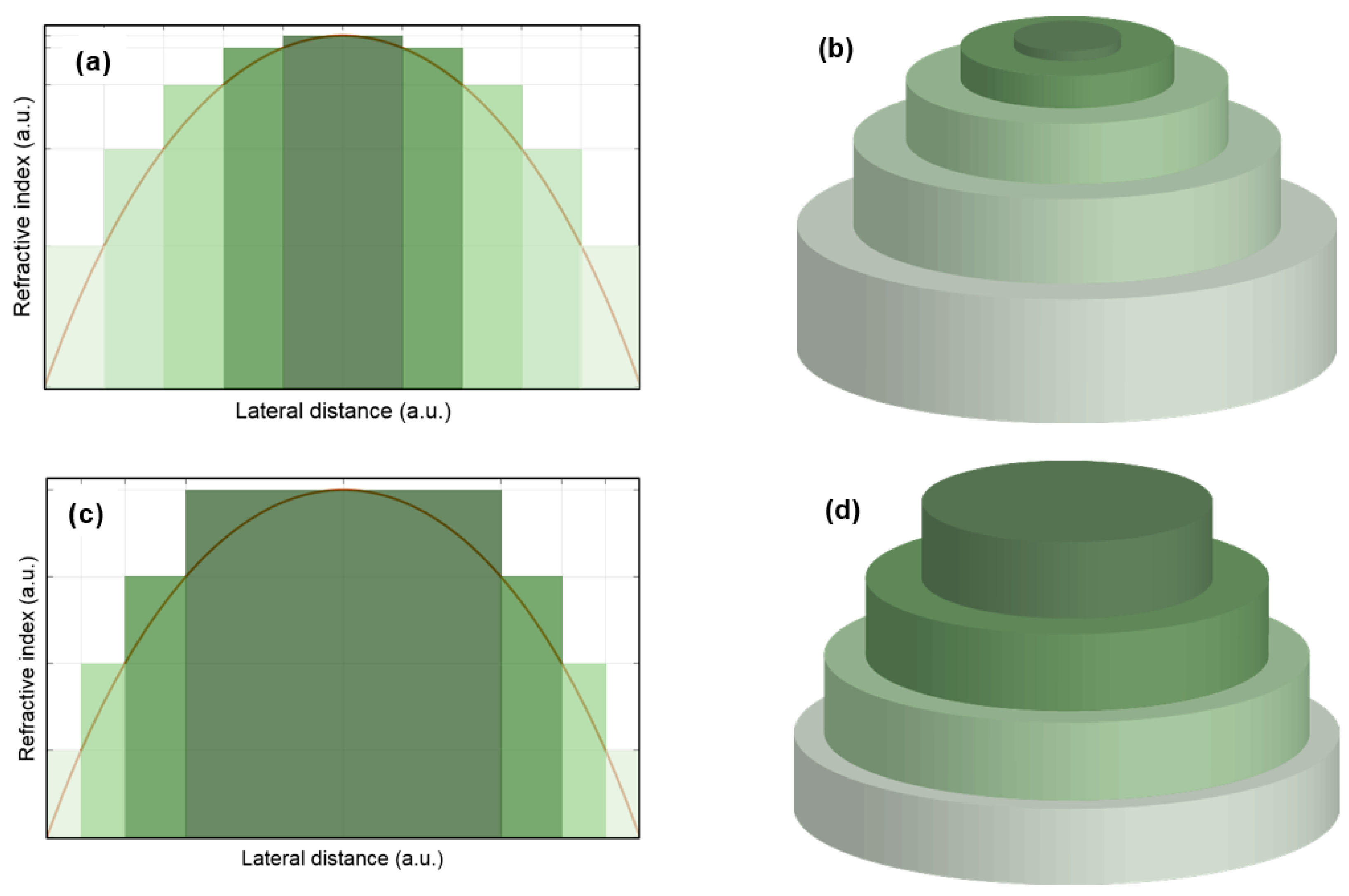
For discretizing a continuous gradient index profile, we propose two schemes. The first is the equilateral step (ELS) profile that consists of the same step width. The second is the equi-index step (EIS) profile that consists of the same index value (i.e., the step height). Graphical examples are shown in Figure 2 with the corresponding surface topology of the devices for each scheme.
In the EIS scheme, the step width at the rim of the element gradually becomes narrower, which reflects the steeper slope at the rim of the index profile. Although this approach resembles the multi-level phase encoding of diffractive microlenses [16], the operation mechanism is different. Surface wave illuminates a 2D Luneburg lens from the side, i.e., along the in-plane direction (see Figure 1b), whereas conventional diffractive lenses are orthogonally illuminated (i.e., along the out-of-plane direction). The large number of steps will create too narrow steps at the rim, which are difficult to fabricate. Therefore, the smallest number of steps for an optimal performance is of great interest. The 2D FDTD simulations are applied to verify the performance by assessing the field distributions near the Luneburg lens. The upper limit for the number of steps (N) is set to be 20 for both ELS and EIS schemes, and N is varied down to 2 with an interval of 1. When the number of steps is sufficiently large, e.g., N > 6, the response of the lens shows no difference form the case of the continuous index profile. For instance, ELS N = 10 case in Figure 3d leads to an identical result as the continuous-profile device in Figure 3e. For the qualitative comparison, the simulated intensity distributions of N = 4, 5, 6 and 10 for the ELS scheme are presented in Figure 3. The focal spot starts to show noticeable degradation from N = 4, see Figure 3a. Therefore, the case of N = 5 is determined to be the optimal number of steps (Nopt) for the ELS scheme. Figure 4 shows the simulation results for N = 3, 4, 5 and 10 of the EIS scheme. Here, the case of N = 3 still shows a relatively good focal spot. However, stronger side lobes start to be prominent. The case of N = 4 produces a focal spot as good as that of larger Ns. Therefore, we determine Nopt = 4 for the EIS scheme. In the following section, we will investigate the Luneburg lens on the BSW platform by directly applying the optimal number of steps, Nopt = 5 and 4 for the ELS and EIS schemes, respectively.
3. Bloch Surface Wave and Multilayer Design
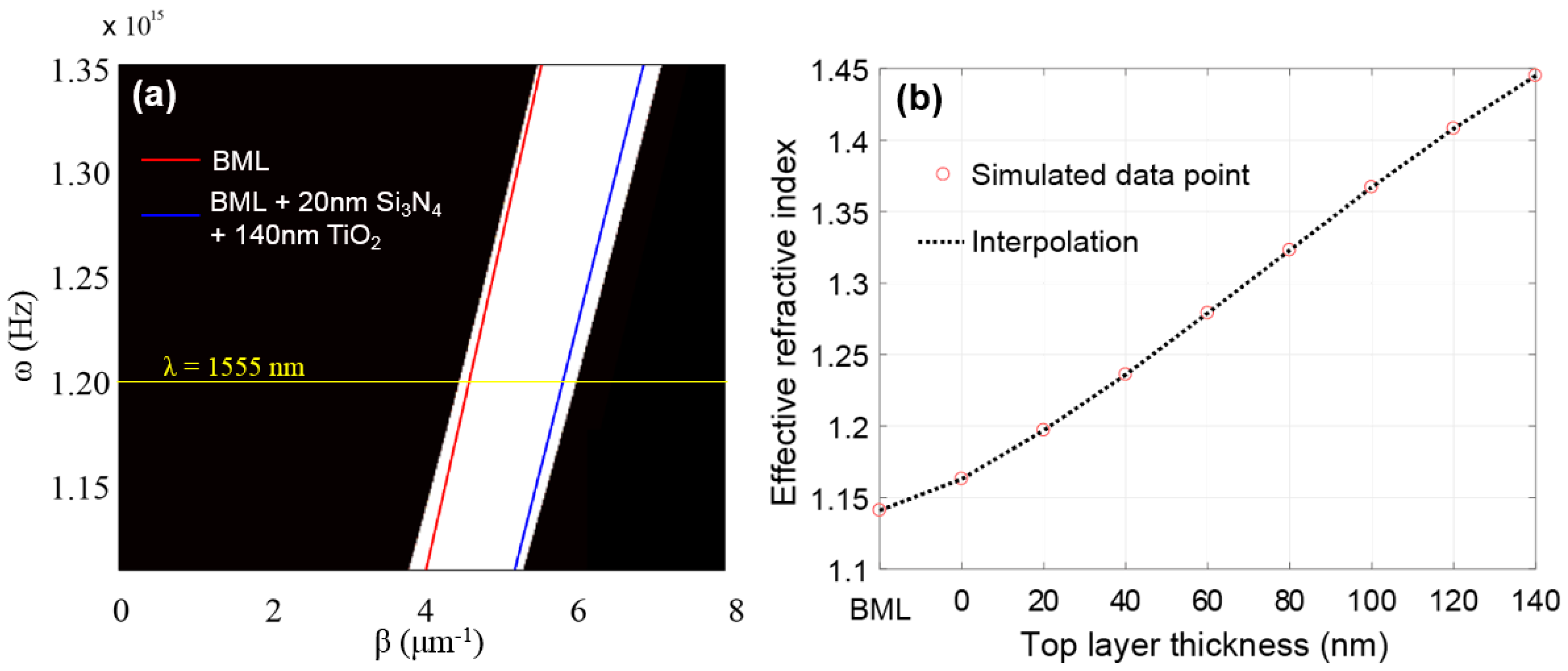
BSWs are supported at the edge of a truncated 1D periodic dielectric media, i.e., a dielectric multilayer serving as 1D photonic crystal [17]. BSW are sustained in the frequency region of the localized photonic band-gap. The band-gap denies propagation into the half space containing the multilayer structure. Since the propagation constant of the mode is outside the light cone of the medium in the other half space, a surface mode is supported. For designing the multilayer for desired BSWs, the band-gap diagram and dispersion curves can be calculated by the transfer matrix method (TMM) [17] or numerical methods, e.g., eigenmode solver CAMFR [18]. In this study, the designed multilayer stack consists of six periods of silicon nitride (Si3N4, nSi3N4 = 1.94, t = 283 nm) and silicon dioxide (SiO2, nSiO2 = 1.47, t = 472 nm), where t being thickness. We call this stage of the multilayer “bare multilayer (BML)”. An additional 20-nm Si3N4 is added on the top of the periodic layers as a defect layer. Finally, the device layer, 140-nm titanium dioxide layer (TiO2, nTiO2 = 2.23), is added on the defect layer. The dispersion curves with corresponding band-gap diagram of the current chip design is shown in Figure 5a, where ω (=2π∙c/λ) being the angular frequency with c the speed of light and β (=k∙sinθ) being the wave number of the BSW with k the wave number in the glass substrate and θ the incident angle in the Kretschmann configuration. Accordingly, an effective index (neff) of a BSW is defined as
which can be simplified to be
with nsub the refractive index of the substrate. The dispersion curves of the BML indicates the lowest effective index, neff = 1.141 for λ = 1555 nm with nsub = 1.444 and θ = 52.2°. Adding the defect layer and the top device layer augments the effective index and increasing the thickness of the top layer moves the dispersion curve towards the right-side band edge, where the larger wavenumber imposes the larger index of the surface mode. Like this, varying the thickness of the top element allows adjusting the effective index contrast. Therefore, the thickness stepping of this device layer can produce the stepwise index profile. The relation between the top layer thickness and the effective index are obtained by TMM for the target λ = 1555 nm, see Figure 5b, where the empty circle markers are the calculated data points and the dashed line is the result of interpolation. The interpolation shows a good linear behavior. For higher thickness of the top layer, the increase of the effective index will be saturated. Only the linear range of the neff is taken into account. In this design, the maximum index contrast (Δnmax) equals approximately 0.3.
4. Stepwise Luneburg Lens on the BSW Platform
To adapt the gradient index profile of Figure 1 to the effective index range of the BSW, we linearly scale the index profile with n0 = 1.14, which is the effective index of the surface mode in the surrounding background (i.e., the BML). This adapted index profile is applied to both the ELS and EIS schemes shown in Figure 6 as solid curves. We apply the optimal number of steps to discretize the continuous profile, Nopt = 5 and 4 for the ELS and EIS schemes, respectively. Such stepping schemes of the gradient index profile for the BSW are depicted in Figure 6. For the simplicity in the profile stepping, we set the radius of the lens R = 5 μm, which leads to the lateral width of the step for the ELS scheme equal to 1 μm. As shown in Figure 5b, designed BSW devices allow almost linear conversion between the top layer thickness and the effective index. Therefore, the stepwise index profile can be obtained by patterning the top layer similar to the surface topologies shown in Figure 2b,d.
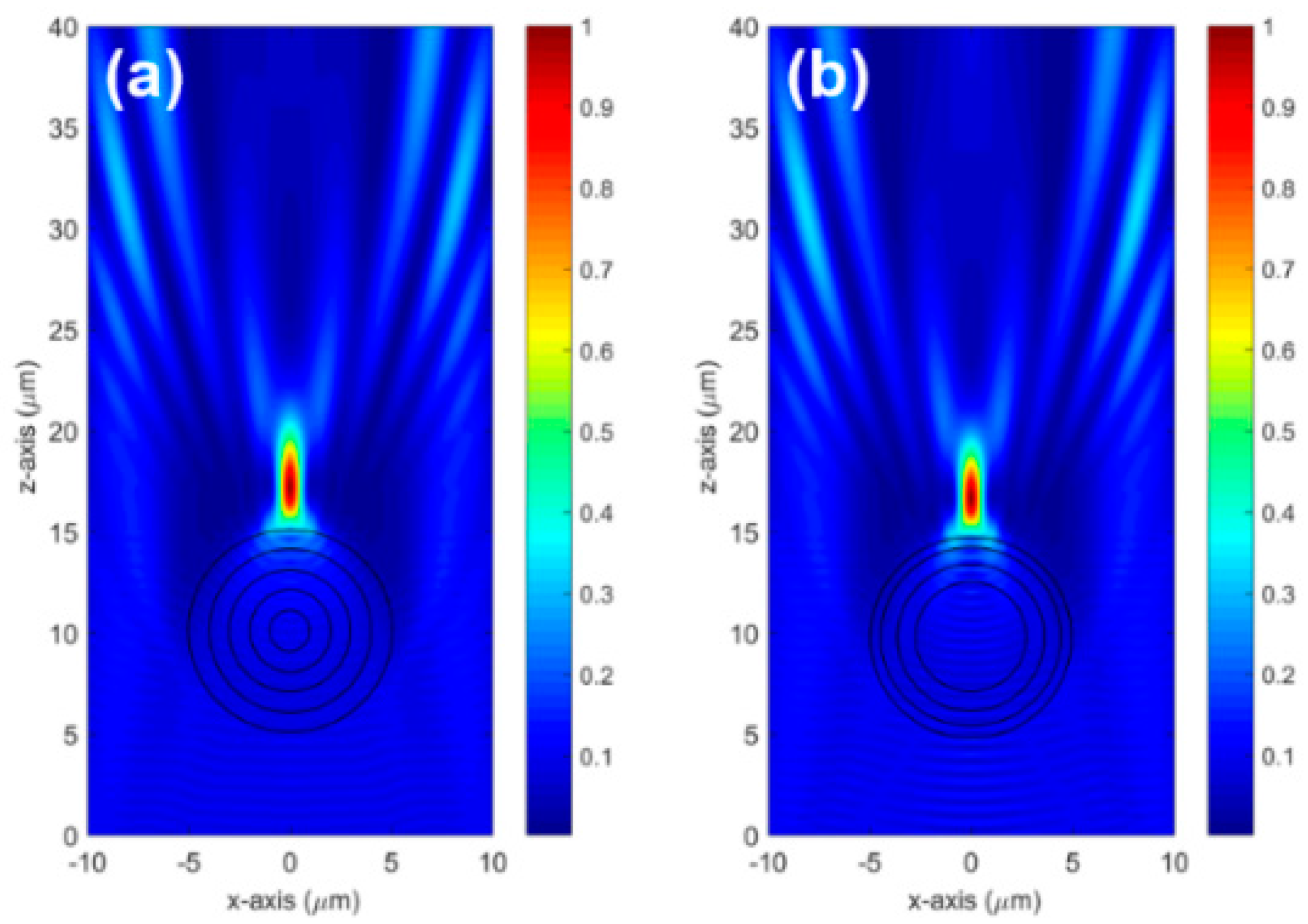
The intrinsic limitation of BSW systems is the maximum achievable index contrast, which is rather lower than that of conventional “glass/air” optical systems, where typical Δn equals 0.5. In this study, the designed multilayer yields Δnmax equal to approximately 0.3. Therefore, the lower refractive power loosens the focusing effect, and eventually pushes the focal spot position away from the shadow-side curvature of the lens, as shown in Figure 7, where the conventional circular geometry Luneburg lenses with the ELS N = 5 and EIS N = 4 are simulated. This lower Δn can be compensated for by increasing the optical path length of the component [14]. To do this, we elongate the circular geometry to a prolate ellipse. Figure 8 shows the prolate elliptical geometries with the aspect ratio (A = h/w) varying from 1.1 to 1.5, where the minor axis diameter w is fixed to 10 μm and the major axis diameter h is varied from 11 to 15 μm with an interval of 1 μm.
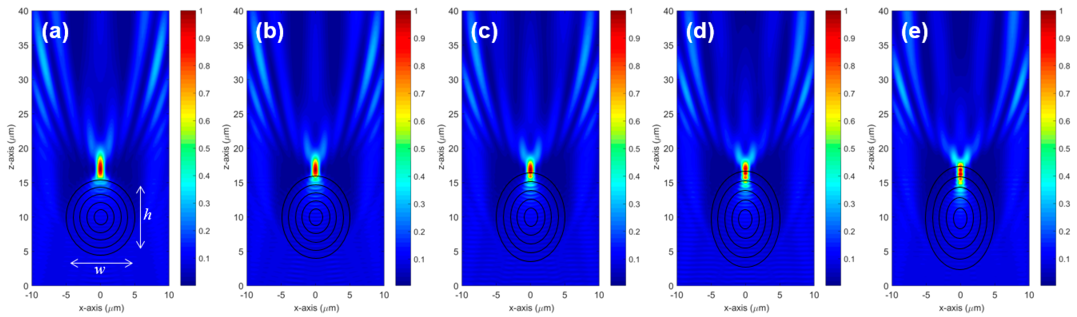
When the aspect ratio rises, the focal spot comes closer to the lens and the confinement becomes tighter. When the aspect ratio is too large, e.g., A = 1.5, the focal spot is totally buried in the lens body. For the ELS case, A = 1.4 shows the best confinement of the focal spot just on the curvature of the Luneburg lens. The same elongation scheme is applied to the EIS profile (see Figure 9). Similar behavior of the focal spot is observed, the increase of A brings the focal spot back to the lens and the confinement gets better. However, for the EIS case, dragging the focal spot towards the lens is stronger than the ELS case, see Figure 9d,e, which show totally buried focal spots. In the EIS case, the best focal spot is acquired for A = 1.3.
5. Conclusions
We have investigated the GRIN optics components on the BSW devices using a 2D FDTD numerical method. For the demonstration, we consider a Luneburg lens, which generates a strong focal spot on the shadow-side curvature. Our approach is to use a stepwise index profile instead of a continuous gradient index profile, which is difficult to achieve in fabrication. We propose two stepping schemes, the equilateral step and equi-index step. First, we determine the smallest number of index profile steps Nopt for optimal performances. We have found that Nopt = 5 for the ELS and 4 for the EIS schemes perform as good as the continuous index profile. We apply Nopt to the BSW platform, whose Δnmax = 0.3. Lower Δn loosens the confinement of the focal spot and pushes it away from the lens. We mitigate this by elongating the lens shape from a circle to a prolate ellipse to compensate the shortened optical path length. The stepwise Luneburg lenses with an elliptical geometry show comparable performance to a standard Luneburg lens. The EIS scheme Luneburg lens seems slightly better than the ELS in terms of the smaller number of steps and the smaller aspect ratio of the ellipse. Considering the fabrication, the EIS is also better because it leads to equal step height of the patterning, which is more practical. Our study can shed a new light on flexible beam shaping and manipulation of the Bloch surface waves with GRIN optics concept.
Acknowledgments
This research is supported by the Swiss National Science Foundation (SNSF FN200020-135455).
Author Contributions
Myun-Sik Kim conceived and designed the study; Babak Vosoughi Lahijani performed the FDTD simulations; Myun-Sik Kim and Hans Peter Herzig wrote the paper.
Conflicts of Interest
The authors declare no conflicts of interest.
References
- Raether, H. Surface Plasmons on Smooth and Rough Surfaces and on Gratings; Springer: New York, NY, USA, 1988. [Google Scholar]
- Berini, P. Long-range surface plasmon polaritons. Adv. Opt. Photonics 2009, 1, 484–588. [Google Scholar] [CrossRef]
- Dubey, R.; Barakat, E.; Häyrinen, M.; Roussey, M.; Honkanen, S.K.; Kuittinen, M.; Herzig, H.P. Experimental investigation of the propagation properties of bloch surface waves on dielectric multilayer platform. J. Eur. Opt. Soc. Rapid Publ. 2017, 13, 5. [Google Scholar] [CrossRef]
- Yu, L.; Barakat, E.; Di Francesco, J.; Herzig, H.P. Two-dimensional polymer grating and prism on Bloch surface waves platform. Opt. Express 2015, 23, 31640–31647. [Google Scholar] [CrossRef] [PubMed]
- Yu, L.; Barakat, E.; Sfez, T.; Hvozdara, L.; Di Francesco, J.; Herzig, H.P. Manipulating Bloch surface waves in 2D: A platform concept-based flat lens. Light Sci. Appl. 2014, 3, e124. [Google Scholar] [CrossRef]
- Descrovi, E.; Sfez, T.; Quaglio, M.; Brunazzo, D.; Dominici, L.; Michelotti, F.; Herzig, H.P.; Martin, O.J.F.; Giorgis, F. Guided Bloch Surface Waves on Ultrathin Polymeric Ridges. Nano Lett. 2010, 10, 2087–2091. [Google Scholar] [CrossRef] [PubMed]
- Sfez, T.; Descrovi, E.; Yu, L.; Quaglio, M.; Dominici, L.; Nakagawa, W.; Michelotti, F.; Giorgis, F.; Herzig, H.P. Two-dimensional optics on silicon nitride multilayer: Refraction of Bloch surface waves. Appl. Phys. Lett. 2010, 96, 151101. [Google Scholar] [CrossRef]
- Yu, L.; Barakat, E.; Nakagawa, W.; Herzig, H.P. Investigation of ultra-thin waveguide arrays on a Bloch surface wave platform. J. Opt. Soc. Am. B 2014, 31, 2996–3000. [Google Scholar] [CrossRef]
- Descrovi, E.; Barakat, E.; Angelini, A.; Munzert, P.; De Leo, N.; Boarino, L.; Giorgis, F.; Herzig, H.P. Leakage radiation interference microscopy. Opt. Lett. 2013, 38, 3374–3376. [Google Scholar] [CrossRef] [PubMed]
- Angelini, A.; Barakat, E.; Munzert, P.; Boarino, L.; De Leo, N.; Enrico, E.; Giorgis, F.; Herzig, H.P.; Pirri, C.F.; Descrovi, E. Focusing and Extraction of Light mediated by Bloch Surface Waves. Sci. Rep. 2014, 4, 5428. [Google Scholar] [CrossRef] [PubMed]
- Dubey, R.; Vosoughi Lahijani, B.; Barakat, E.; Häyrinen, M.; Roussey, M.; Kuittinen, M.; Herzig, H.P. Near-field characterization of a Bloch-surface-wave-based 2D disk resonator. Opt. Lett. 2016, 41, 4867–4870. [Google Scholar] [CrossRef] [PubMed]
- Santi, S.; Musi, V.; Descrovi, E.; Paeder, V.; Di Francesco, J.; Hvozdara, L.; van der Wal, P.; Lashuel, H.A.; Pastore, A.; Neier, R.; et al. Real-time Amyloid Aggregation Monitoring with a Photonic Crystal-based Approach. ChemPhysChem 2013, 14, 3476–3482. [Google Scholar] [CrossRef] [PubMed]
- Zentgraf, T.; Liu, Y.; Mikkelsen, M.H.; Valentine, J.; Zhang, X. Plasmonic Luneburg and Eaton lenses. Nat. Nanotechol. 2011, 6, 151–155. [Google Scholar] [CrossRef] [PubMed]
- Kim, M.-S.; Vosoughi Lahijani, B.; Descharmes, N.; Straubel, J.; Negredo, F.; Rockstuhl, C.; Häyrinen, M.; Kuittinen, M.; Roussey, M.; Herzig, H.P. Subwavelength focusing of Bloch surface wave. ACS Photonics 2017, 4, 1477–1483. [Google Scholar] [CrossRef]
- Mao, X.; Yang, Y.; Dai, H.; Luo, D.; Yao, B.; Yan, S. Tunable photonic nanojet formed by generalized Luneburg lens. Opt. Express 2015, 23, 26426–26433. [Google Scholar] [CrossRef] [PubMed]
- Kuittinen, M.; Herzig, H.P. Encoding of efficient diffractive microlenses. Opt. Lett. 1995, 20, 2156–2158. [Google Scholar] [CrossRef] [PubMed]
- Yeh, P.; Yariv, A.; Hong, C.-S. Electromagnetic propagation in periodic stratified media. I. General theory. J. Opt. Soc. Am. 1977, 67, 423–438. [Google Scholar] [CrossRef]
- CAvity Modelling Framework (CAMFR). Available online: http://camfr.sourceforge.net/ (accessed on 1 February 2017).
Figure 1.
(a) Gradient index profile for a standard Luneburg lens in air with n0 = 1 and R = 7.5 μm. (b) Schematic of 2D Luneburg lenses for continuous and stepwise index profiles. Surface wave propagates along the z-axis.
Figure 1.
(a) Gradient index profile for a standard Luneburg lens in air with n0 = 1 and R = 7.5 μm. (b) Schematic of 2D Luneburg lenses for continuous and stepwise index profiles. Surface wave propagates along the z-axis.

Figure 2.
(a) Equilateral step (ELS) scheme of the index profile and (b) the corresponding surface topology of the device; (c) Equi-index step (EIS) scheme and (d) the corresponding surface topology of the device.
Figure 2.
(a) Equilateral step (ELS) scheme of the index profile and (b) the corresponding surface topology of the device; (c) Equi-index step (EIS) scheme and (d) the corresponding surface topology of the device.

Figure 3.
Simulated intensity distributions of Luneburg lenses with the ELS index profile: (a) N = 4, (b) 5, (c) 6 and (d) 10, respectively. Larger Ns (>6) show almost the same response as a Luneburg lens with a continuous GRIN profile. The intensities are normalized. Concentric circles depict the step boundary of the index profile in (a); Here, the smallest step number for an optimal performance (Nopt) is determined to be 5; (e) The result of the continuous-profile device shows an identical result as that of N = 10 shown in (d).

Figure 4.
Simulated intensity distributions of Luneburg lenses with the EIS index profile: (a) N = 3, (b) 4, (c) 5 and (d) 10, respectively. Larger Ns (>6) show almost the same response as the Luneburg lens with a continuous GRIN profile. The intensities are normalized. Concentric circles depict the step boundary of the index profile in (a). Here, the smallest step number for the optimal performance (Nopt) is determined to be 4.

Figure 5.
(a) Band-gap diagram and dispersion curves, obtained by TMM. The clear area is the localized photonic band-gap. The dispersion curve of the BML indicates the lowest effect index, n = 1.141 at λ = 1555 nm. Adding the defect layer and the top device layer moves the dispersion curve towards the right-side band edge, where the larger wavenumber indicates the larger effective index; (b) The relation between the thickness of the top layer and the effective refractive index at λ = 1555 nm. The maximum index contrast equals approximately 0.3.

Figure 6.
(a) Equilateral step (ELS) scheme of the refractive index profile with N = 5, where the step width = 1 μm and R = 5 μm. (b) Equi-index step (EIS) scheme with N = 4. The solid curve is the adapted gradient index profile for the effective index range of the designed BSW system, where the Δnmax = 0.3 and n0 = 1.141. Equivalent height stepping of the top layer will resemble the surface topologies shown in Figure 2b,d.

Figure 7.
Intensity distributions of stepwise Luneburg lens with circular geometry for (a) the ELS and (b) EIS profiles shown in Figure 5. The intensities are normalized. Concentric circles depict the step boundary of the index profile.
Figure 7.
Intensity distributions of stepwise Luneburg lens with circular geometry for (a) the ELS and (b) EIS profiles shown in Figure 5. The intensities are normalized. Concentric circles depict the step boundary of the index profile.

Figure 8.
Intensity distributions of the elliptical shape Luneburg lens of the ELS profile with N = 5: (a) the aspect ratio A = 1.1, (b) 1.2, (c) 1.3, (d) 1.4, and (e) 1.5, respectively. The intensities are normalized. Concentric ellipses depict the step boundary of the index profile.
Figure 8.
Intensity distributions of the elliptical shape Luneburg lens of the ELS profile with N = 5: (a) the aspect ratio A = 1.1, (b) 1.2, (c) 1.3, (d) 1.4, and (e) 1.5, respectively. The intensities are normalized. Concentric ellipses depict the step boundary of the index profile.

Figure 9.
Intensity distributions of the elliptical shape Luneburg lens of the EIS profile with N = 4: (a) the aspect ratio A = 1.1, (b) 1.2, (c) 1.3, (d) 1.4 and (e) 1.5, respectively. The intensities are normalized. Concentric ellipses depict the step boundary of the index profile.
Figure 9.
Intensity distributions of the elliptical shape Luneburg lens of the EIS profile with N = 4: (a) the aspect ratio A = 1.1, (b) 1.2, (c) 1.3, (d) 1.4 and (e) 1.5, respectively. The intensities are normalized. Concentric ellipses depict the step boundary of the index profile.

© 2018 by the authors. Licensee MDPI, Basel, Switzerland. This article is an open access article distributed under the terms and conditions of the Creative Commons Attribution (CC BY) license (http://creativecommons.org/licenses/by/4.0/).
Share and Cite
MDPI and ACS Style
Kim, M.-S.; Vosoughi Lahijani, B.; Herzig, H.P. Stepwise Luneburg Lens for Bloch Surface Waves. Appl. Sci. 2018, 8, 245. https://doi.org/10.3390/app8020245
AMA Style
Kim M-S, Vosoughi Lahijani B, Herzig HP. Stepwise Luneburg Lens for Bloch Surface Waves. Applied Sciences. 2018; 8(2):245. https://doi.org/10.3390/app8020245
Chicago/Turabian StyleKim, Myun-Sik, Babak Vosoughi Lahijani, and Hans Peter Herzig. 2018. "Stepwise Luneburg Lens for Bloch Surface Waves" Applied Sciences 8, no. 2: 245. https://doi.org/10.3390/app8020245
Note that from the first issue of 2016, this journal uses article numbers instead of page numbers. See further details here.