Orbital Angular Momentum Generation and Detection by Geometric-Phase Based Metasurfaces


1
Department of Electrical and Electronic Engineering, The University of Hong Kong, Hong Kong, China
2
HKU Shenzhen Institute of Research and Innovation, Shenzhen 518057, China
3
Key Laboratory of Micro-Nano Electronic Devices and Smart Systems of Zhejiang Province, College of Information Science and Electronic Engineering, Zhejiang University, Hangzhou 310027, China
*
Authors to whom correspondence should be addressed.
Appl. Sci. 2018, 8(3), 362; https://doi.org/10.3390/app8030362
Submission received: 26 January 2018
/
Revised: 16 February 2018
/
Accepted: 18 February 2018
/
Published: 2 March 2018
(This article belongs to the Special Issue Metasurfaces: Physics and Applications)
Abstract
:We present a comprehensive review on the geometric-phase based metasurfaces for orbital angular momentum (OAM) generation and detection. These metasurfaces manipulate the electromagnetic (EM) wave by introducing abrupt phase change, which is strongly dependent on the polarization state of incident EM wave and can be interpreted by geometric phase. Hence, the conventional bulk devices that based on the accumulated phase change along the optical path can be avoided.
1. Introduction
It is well known that electromagnetic (EM) wave carries linear momentum which is associated with the poynting vector. Besides the linear momentum, EM wave has been demonstrated to possess angular momentum (AM), including spin angular momentum (SAM) and orbital angular momentum (OAM) [1]. Circularly polarized wave carries SAM. The SAM is per photon for left-handed circular polarization (LHCP) and per photon for right-handed circular polarization (RHCP), where is the reduced Planck constant. The SAM characterizes the spin feature of photon. Different from the SAM, OAM manifests the orbital rotation of photon and each photon has an OAM of , where l is known as the OAM index and can be any integer. Different values of l correspond to mutually orthogonal OAM states and the number of allowable OAM states for photons is unbounded. Different OAM states have been used to encode information in communications to enhance the channel capacity, both in free space [2,3,4,5,6,7,8,9] and optical fibers [10]. The main problem of practical application of OAM in communications is the significant crosstalk between OAM modes [11,12]. The spatial-dependence and divergency nature of OAM-carrying waves result in the their vulnerability to the atmosphere [13,14] and limited power received at the receiver side [15]. All these facts will degrade the purity of OAM modes. Still, OAM offers a new attractive degree of freedom to EM waves, extending beyond the existing wave features. The optical vortices of OAM beams also find their applications in super resolution imaging [16,17]. OAM can be transferred to particles, which has been applied in optical tweezers [18,19,20]. The exchange of OAM with matter can also be utilized in detecting the rotation of particles [21]. In quantum mechanics, at a single-photon level, OAM modes can be utilized for high-dimensional entanglement [22,23]. Overall, OAM has received great attentions in multidisciplinary research areas [24,25,26,27].
Since OAM has great potentials in various applications, research has been undertaken extensively on its generation. In 1992, Allen et al. first found that a Laguerre-Gaussian (LG) beam with helical wavefront carries well defined OAM [28]. That beam possesses an azimuthal phase term, , where is the azimuthal angle. Before that, Soskin et al. created structured light with helical wavefront by forked gratings [29]. This grating forms the basis of the computer generated holograms (CGHs) for producing light beams with OAM. Afterwards, many other devices for OAM generation have been proposed, such as the cylindrical lens in 1993 [30], spiral phase plates (SPPs) in 1994 [31], q plates in 2006 [32]. Lately, OAM has been analyzed at radio frequencies. Antenna arrays [33], traveling-wave antennas [34] and circularly polarized patch antennas [35] which radiate EM waves carrying OAM have been demonstrated.
Recent advances in versatile metasurfaces also expedite powerful and convenient design routes for OAM generation [36,37,38,39]. The concept of metasurface originates from the conventional frequency selective surfaces (FSSs) [40]. They are composed of man-made subwavelength scatterers with varying geometry and orientation. Therefore, they go beyond the conventional FSSs due to the high feasibility of tailoring the geometry and orientation of the ultracompact scatterers. Metasurfaces locally alter the wave properties by the abrupt phase change at the scatterers. By varying the geometry or orientation, scatterers can cover a total phase shift so that arbitrary beam forming can be achieved. Meanwhile, scatterers can be designed to simultaneously change the wave amplitude [41]. Besides the electric response, they can have the magnetic response. Scatterers have both electric and magnetic responses form the Huygens metasurface [42]. The magnetic response helps to compensate the impedance mismatch at the metasurface interface so that nearly perfect efficiency can be achieved.
Although there are various designs in different types and suitable for different application scenarios, the design principles for OAM generation lead to one common rule: the introduction of the azimuthal phase term to EM waves. Generally, they fall into two categories: independent and dependent on the wave polarization.
The first scheme employs isotropic materials, such as SPPs, CGHs. is introduced in a SPP based on the accumulated spatially varying optical path [43,44,45]. They are usually implemented at optical frequencies. At lower frequencies, the device would become bulky unless some flatten techniques are employed [46,47,48]. CGHs are diffractive optical elements and they produce light with different OAMs according to the diffraction orders [49,50,51,52]. Alternatively, the excitation of an antenna or antenna array can be modulated directly to satisfy the required phase condition so that an OAM wave can be radiated out [53,54]. can also be produced based on the abrupt phase shift at scatterers on a metasurface. By varying the geometry of the scatterer, its resonant frequency is changed so that the phase shift varies at the designed frequency. A total phase shift is achieved after optimization; and successful generation of different OAM states has been reported in [55,56]. Lately, tunable scatterers loaded by varactor diodes are proposed for convenient multiple OAM-mode generation [57]. Scatterers can also be made anisotropic to achieve independent control of different polarizations. However, even if the response of scatterers is polarization dependent, the helicity of the produced OAM does not depend on the polarization state of incident wave. In other words, the helicity is fixed. While for the second scheme, it is an opposite scenario.
The second scheme is based on the conversion and coupling between SAM and OAM. This process occurs in inhomogeneous and anisotropic media, such as q plates [58,59]. Q plates shift the circular polarization state from left to right or right to left and have spatially varying optical axis [60]. Their behaviors can be explained by AM conservation law. The flip of the circular polarization state indicates a change of in SAM. When the q plate is cylindrically symmetric, the total AM is conserved so that the output wave must carry an OAM of . When the q plate is not cylindrically symmetric, it introduces extra AM to the system so that different orders of OAM can be generated in the output wave. Q plates are usually made by liquid crystals, owning to their flexibility and anisotropic properties. By tuning the temperature or external voltage, the birefringent retardation in liquid crystals varies, so that the conversion efficiency can be tuned [61,62]. The maximum efficiency is obtained when the retardation is . Metasurfaces have been used to implement the feature of q plates [63,64,65,66,67]. The flip of the circular polarization state achieved by anisotropic scatterers and rotation of the scatterers is an analogue to the rotation of optical axis of a q plate, along with the introduction of geometric phase. Therefore, this type of metasurfaces is known as geometric-phase metasurfaces. Unlike the metasurfaces employing the first scheme, geometric-phase metasurfaces produce OAM along with the change of the polarization state of the output wave, which is fundamentally different from the first scheme. The handness of the produced OAM depends on the incident SAM. Hence, geometric-phase metasurfaces show their high flexibility in the manipulation of OAM because they enable the coupling and interchange between SAM and OAM.
In communications, detection of OAM at the receiver side is required. Although OAM detection is just a reciprocal process of OAM generation, it is much more challenging due to the degraded OAM states after the propagation. OAM detection can be classified into three categories, mode analysis based on field data [68,69,70], observation of OAM induced effects such as the rotational Doppler shift [71,72,73] and the beam reforming by adopting holographic technology [74]. The first approach needs to acquire all the three components of electric and magnetic fields so that the OAM can be calculated explicitly [68]. Alternatively, one can measure the phase gradient that is equal to the OAM index l [75]. In the third approach, by using a hologram, the OAM modes can be projected into a detectable Gaussian mode [76]. Geometric-phase metasurfaces can be used to implement the holograms and have the advantages of low profile and high tuning flexibility.
In this review article, we concentrate on the current research of the OAM generation and detection by geometric-phase based metasurfaces. We start by the introduction of geometric phase. Then, we go over several novel metasurfaces for OAM generation. The induced geometric phases on the metasurfaces can be in both discrete and continuous formats. Their geometries, working principles and novel functionalities have been reviewed and discussed in detail. At last, a method for OAM detection is reviewed.
2. Geometric Phase
When a light changes its initial polarization state to a final polarization state along different paths on a Poincaré sphere, the final polarization states will have difference phases, known as geometric phase [77]. In the following, we derive the geometric phase when the SAM shifts from to through an anisotropic scatterer with different orientations.
The behavior of a scatterer can be modelled by Jones matrix . It connects the polarization state of the scattered wave with that of an incident wave:
where and are the x and y components of the incident electric field. and are the corresponding components of the scattered electric field.
Jones matrix under the circular basis can be obtained by coordinate transformation,
where + and − represent the right circularly polarized (RCP) and left circularly polarized (LCP) components.
If the scatterer achieves a perfect conversion between RCP wave and LCP wave, it must satisfy and , so that the Jones matrix is written as,
Clearly, there are only off-diagonal entities in , indicating the flip between RHCP and LHCP. Axially rotating the scatterer by an angle of will result in a new Jones matrix,
also has only the non-zero off-diagonal items. Besides, an additional phase factor is introduced. This phase is the so-called geometric phase. The scatterers on a geometric-phase metasurface cover a phase shift by changing the rotation angle .
To generate OAM, geometric phase is utilized to construct the required phase profile, of an OAM wave. Apparently, to generate an OAM of order l, scatterers on a metasurface with azimuthal location should be designed to provide a phase change of , i.e., . The sign depends on the incident circular polarization state. The value of is known as the topology charge q of the metasurface. Apparently, the OAM order l is determined by q and should be double of its value.
The geometric phase itself does not depend on the frequency so that broadband metasurfaces could be potentially designed. For a perfect (100%) conversion, the condition and should be strictly satisfied, i.e., and should have the same unit amplitude and phase difference. Achieving these conditions by scatterers on resonance will inevitably limit the bandwidth. When the requirement is not strictly satisfied, the co-circularly polarized component needs to be filtered out. Only the cross-circularly polarized component carries OAM.
3. Metasurfaces for OAM Generation
Various prototypes of scatterers that can totally or partially convert the R/LHCP to L/RHCP have been proposed for OAM generation. Plasmonic scatterers, such as the golden nanorods in [78], L-shaped gold nanoantennas [79], rectangular split-ring resonators (SRRs) in [80]; apertures opened on metals, such as the elliptical nanoholes in [81]; and dielectric particles have been demonstrated at optical regime. At microwave frequencies, multi-layered unit cells have been reported to achieve high efficiency [82,83]. The scatterers and their composite metasurfaces are usually simulated by numerical simulation software, such as finite element method and finite integration technique-based CST Microwave Studio [84,85,86,87,88,89], finite element method-based HFSS, finite-difference time-domain method-based Lumerical [90], and COMSEL. Some of them can be analytically modelled [87] or simulated by approximate models [84,89]. Lately, an efficient modelling is applied to integral equation solvers to accelerate the simulation of metasurfaces in multiscale [91].
3.1. Artifical PEC-PMC Metasurface
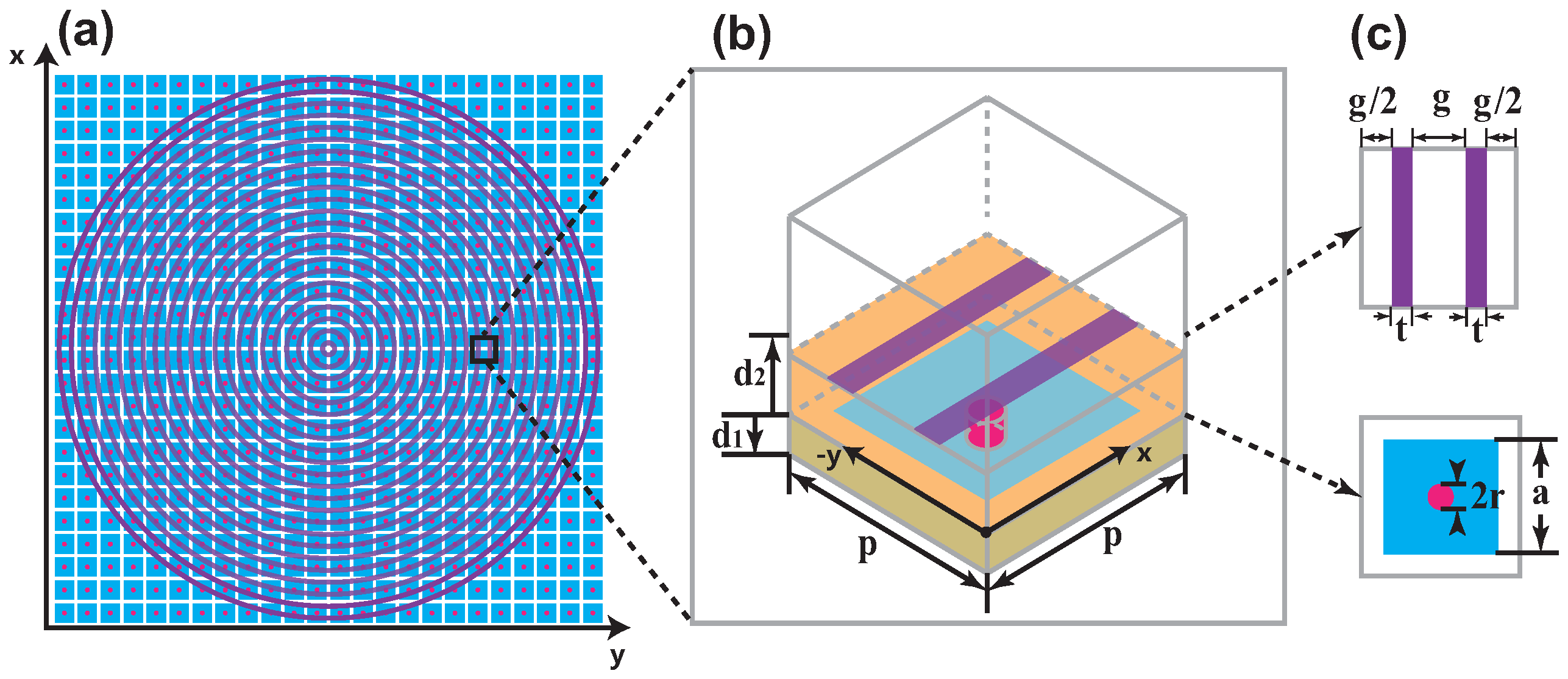
We propose a composite perfect electric conductor (PEC)-perfect magnetic conductor (PMC)-based anisotropic metasurface [84]. A PEC surface is designed for x polarization so we have . An artificial PMC surface is put beneath the PEC surface so that is satisfied. The proposed novel metasurface is depicted in Figure 1. The metasurface has two dielectric layers and a ground plane. It is composed of scatterers shown in Figure 1b. The metal strips on the top layer function as a parallel plate waveguide and allow the perfect transmission of y polarized wave while the x polarized wave will be totally reflected with phase shift. The metal patch in middle together with the via and ground plane forms the well-known mushroom-like high-impedance surface. By operating at its resonant frequency, it can be considered as a PMC surface and will reflect the transmitted y polarized wave from the metal strips with a zero phase shift. The whole metasurface is built by distributing the scatterers with varying orientations according to their azimuthal locations. It should be noted that the mushroom-like high-impedance surface is isotropic, therefore, there is no need to change the orientations of mushrooms. For the PEC surface, by setting the rotation angle , rotation of the strips will lead to a series of concentric loops. The resultant generated OAM order is 2 or −2, where the sign depends on the incident circular polarization state.
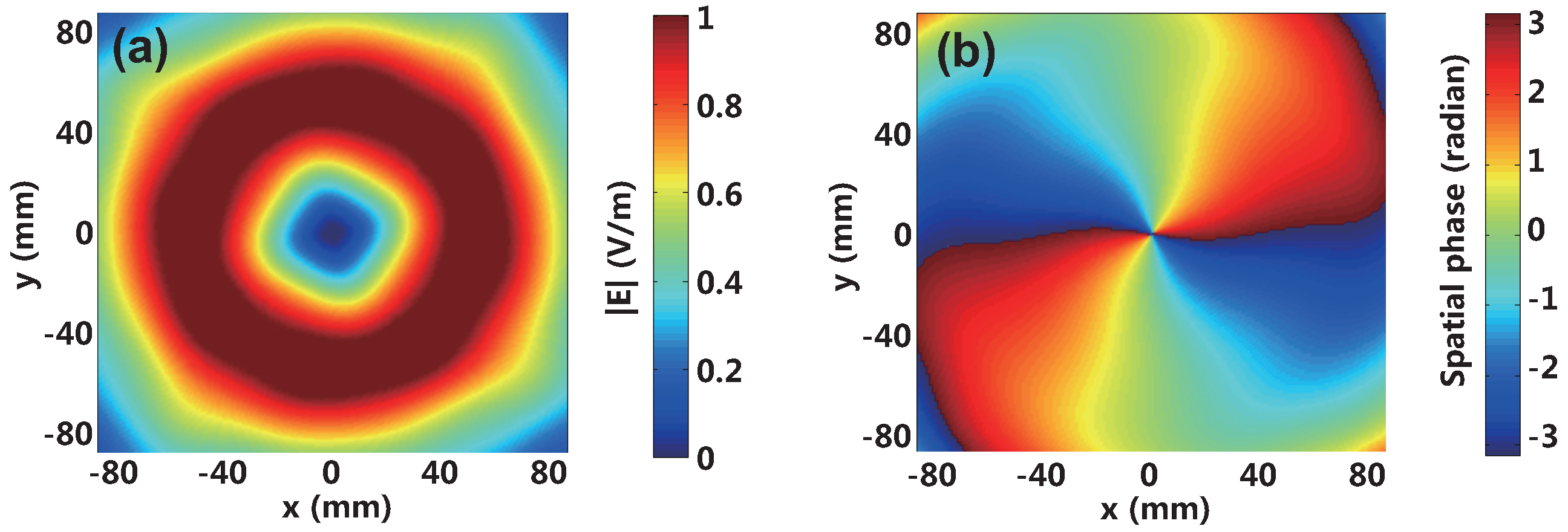
The metasurface is designed at 6.2 GHz and can be conveniently fabricated using printed circuit board (PCB) technique. Full-wave simulation was done in CST MWS. The right circularly polarized plane wave is used as incident wave. Figure 2 shows the amplitude and phase distributions of the reflected electric fields at a transverse plane of mm. An amplitude null can be observed in Figure 2a, which results from the phase singularity at the center for an OAM-carrying wave. In Figure 2b, the phase accumulated along a full circular path around the center is , indicating an OAM of order −2. A unique feature for the PEC-PMC metasurface is that the scatterers on top layer are not on resonance or discrete but continuously connected. Thus, the near-field pattern is quite smooth without any evanescent field component scattered by discrete scatterers.
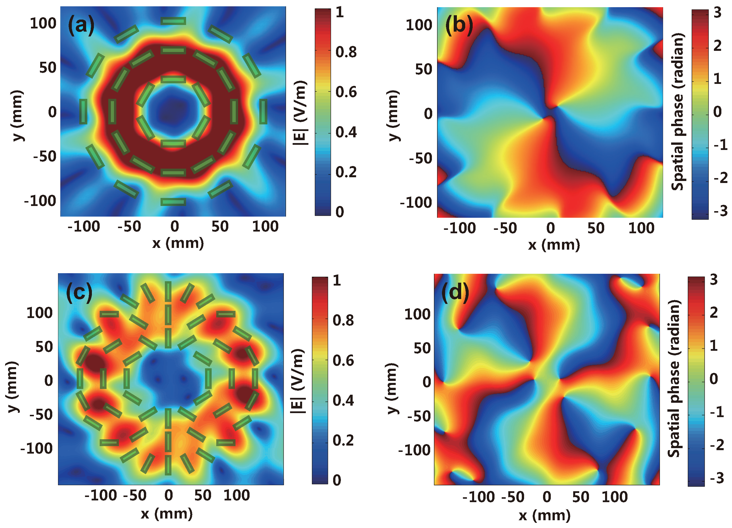
For the generation of OAM of other orders, a similar PEC-PMC metasurface but with discrete dipole scatterers on the top layer is proposed. The dipoles are designed to totally reflect the x polarized wave with phase shift at 6.2 GHz. Two cases for generation of OAM of order −2 and −4 are shown in Figure 3. The amplitude and phase of the reflected field are drawn at a transverse plane of mm. The distributed dipole scatterers are also depicted in Figure 3a,c. The field patterns verify the desired OAMs have been generated. However, due to the influence of the discrete dipoles, the amplitude distribution is not uniform any more and ripples are observed in the phase distribution. As discussed before, the ripples are caused by evanescent field components scattered by the dipoles. The distortion only exists in the near field and will become less serious when the observation plane moves further away from the metasurface.
3.2. Ultrathin Complementary Metasurface
The efficiency of reflective metasurface could be very high by placing a reflector beneath it, while for transmissive metasurface, high efficiency cannot be easily achieved due to the reflection at the metasurface-air interface stemming from the impedance mismatch. In the following, we show our designed double-layer complementary metasurface for OAM generation with high efficiency [85].
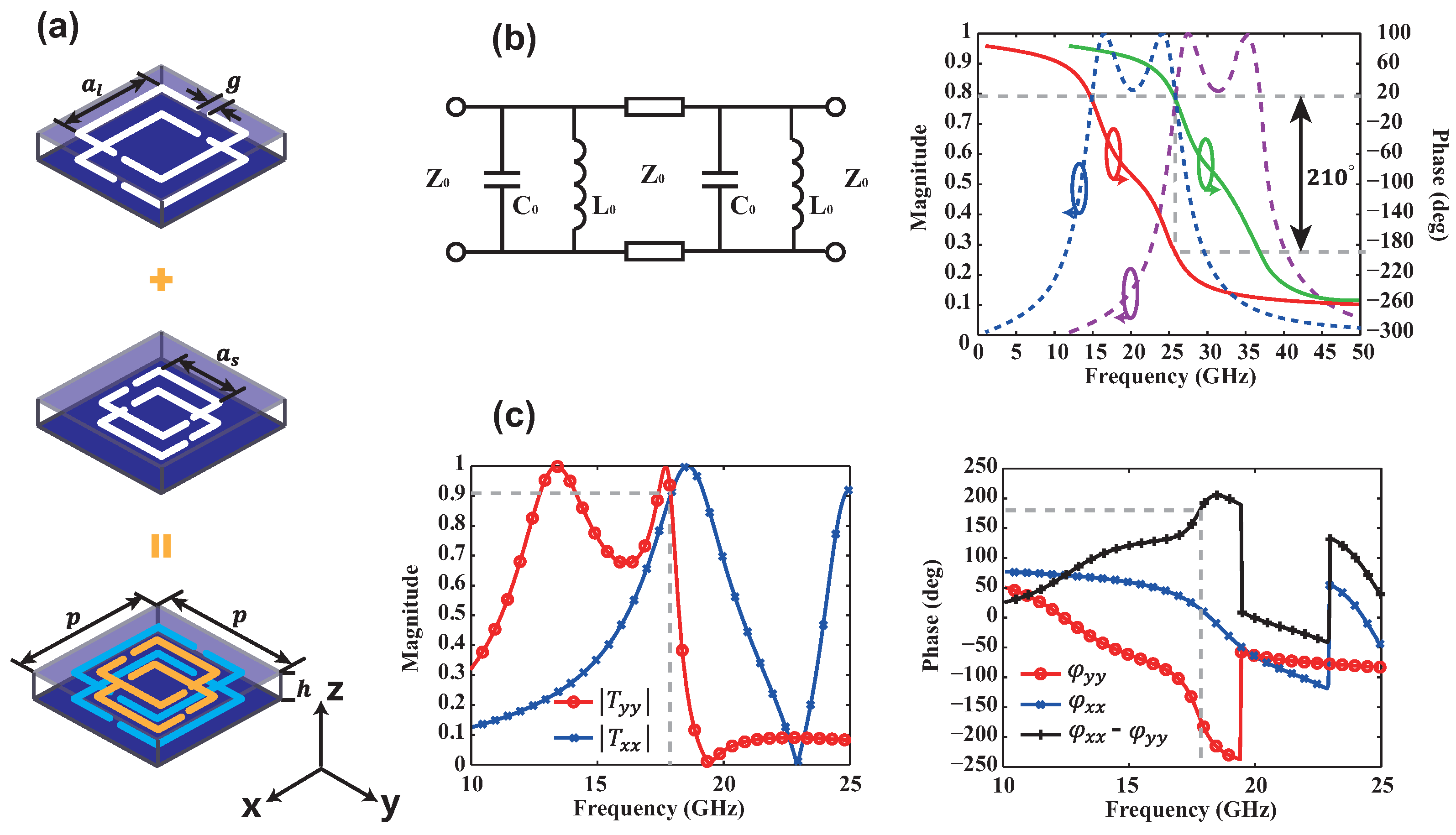
The unit cell is shown in Figure 4a. Each unit cell consists of four complementary split-ring resonators (CSRRs) with two different sizes and orientations. The equivalent circuit and its response for each pair are drawn in Figure 4b. It is clear that the double-layer structure offers two parallel inductor-capacitor (LC) resonant circuits so that we have a sufficient tunable range to achieve the design objective, i.e., the same high transmittance from the two pairs as well as the phase difference between their transmission coefficients. Figure 4c presents the full-wave simulation results of unit cell. At 17.85 GHz, magnitudes of the co-transmission coefficients are both 0.91 and their phase difference is , indicating a 81% circular polarization conversion efficiency. This double-layer structure can be fabricated on a conventional PCB.
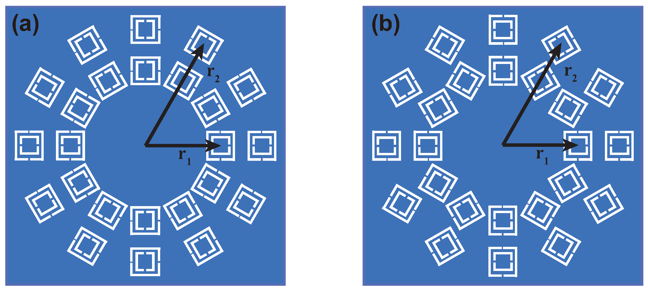
Then a whole metasurface is built by arranging the unit cells with varying orientations. Two metasurfaces with topological charges of 1 and 2 are designed. The top view of the designed metasurface is shown in Figure 5. Each metasurface includes 24 scatterers, whose centers describe two circles with the radius of and .
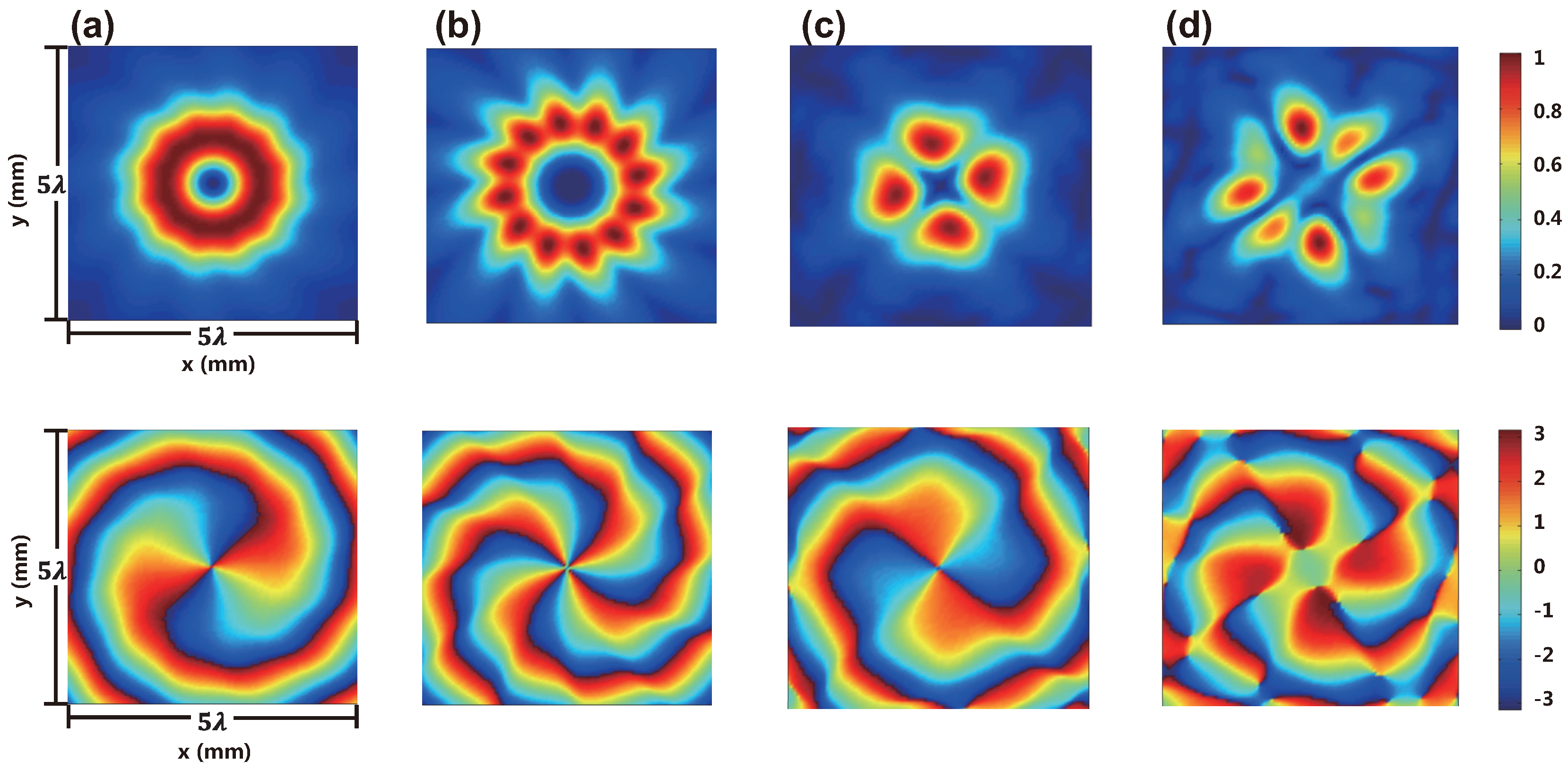
The EM responses from the metasurfaces are calculated by an equivalent dipole model and CST MWS. In the equivalent dipole model, each unit cell is considered to be two orthogonal magnetic dipole sources with the orientations aligned with the long side of the CSRRs. Therefore, the EM response from the whole metasurface is considered to be a sum of the response from magnetic dipoles with varying orientations. This approach is useful to simulate a metasurface comprising a great number of scatterers that can be treated as point sources with arbitrary strengths, locations and orientations. The calculated field distributions are shown in Figure 6. The results verify the successful generation of OAM. The divergence between the results from the dipole model and the full-wave simulation comes from the coupling between unit cells.
3.3. Metasurface Fork Gratings
The transmission function for a diffraction grating for OAM generation is written by
where r is the radial position, is the azimuthal position, is the weight of the mth beam, is the corresponding OAM index, and , are the transverse wave numbers of the mth beam. It can be considered as a hologram resulting from the interference of a plane wave and a OAM wave.
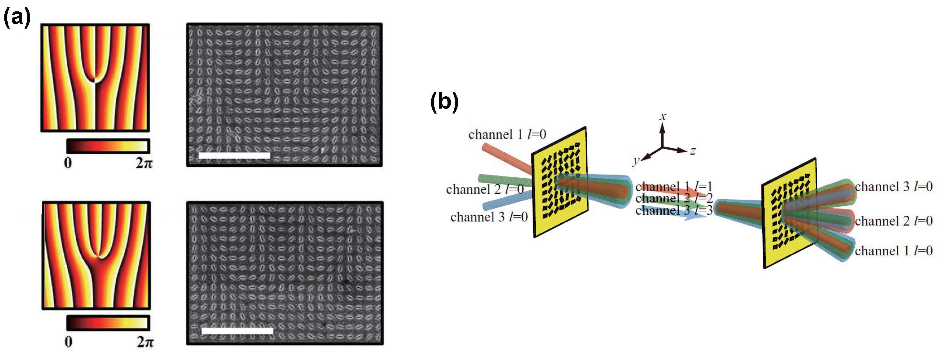
The transmission function is calculated based on the design requirement and the phase information is extracted and reconstructed using geometric-phase metasurfaces. We show two designs in Figure 7 [86,92]. They are formed by nanoslits with varying orientations. Figure 7a shows the phased holograms and the corresponding distributions of nanoslits for a single OAM beam generation. During the fabrication process, first, an 80-nm-think aluminum film is deposited on glass through thermal evaporation process. Then, the nanoslits array is fabricated through focus-ion-beam method. Figure 7b illustrates a general map of three-OAM-channel multiplexing and demultiplexing using metasurfaces. Two identical metasurfaces are used for the multiple OAM-beam generation and separation, respectively. In both cases of Figure 7, the metasurfaces are illuminated by a circularly polarized wave and the cross-circularly polarized component carries OAM.
3.4. Metasurface for OAM-Carrying Vector Beams Generation
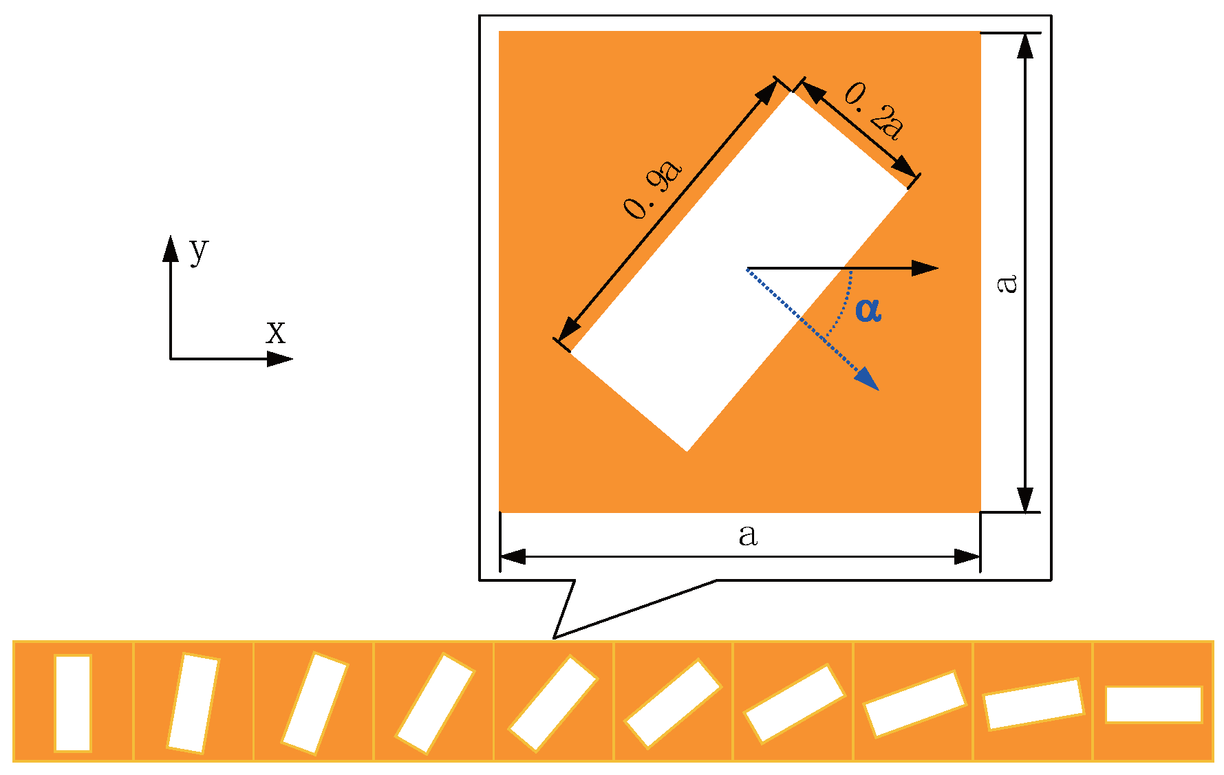
In the previous discussion, the metasurfaces generate circularly polarized waves with OAM. In the following, we will review several pieces of research work dealing with vector fields carrying OAM [93,94]. The polarization of vector fields is represent by , where m is the polarization order and is the initial polarization. To generate a vector field, a linear polarizer shown in Figure 8 is used. It composes of rectangular apertures and the transmitted wave is linearly polarized along the direction that is vertical to the long axis of the aperture. When the linear polarizers are oriented to different directions according to their locations, the polarizations are varied locally. The aperture with is modelled by Jones matrix:
Then, the Jones matrix for a rotated aperture is written as
If the incident wave is circularly polarized, i.e., (plus sign for LHCP and minus sign for RHCP), the transmitted field is expressed by
From (8) and (9), we can notice that the output wave is linearly polarized with a geometric phase of . The linearly polarized wave can be decomposed into two circularly polarized waves. The co-circular polarization does not have the phase term and the cross-circular polarization has the term of . It should be emphasized that unlike the previous derivation that the conversion efficiency can reach 1, the transmitted power after the linear polarizer is only half of the power in the incident wave and each transmitted circularly polarized component takes half of the total transmitted power.
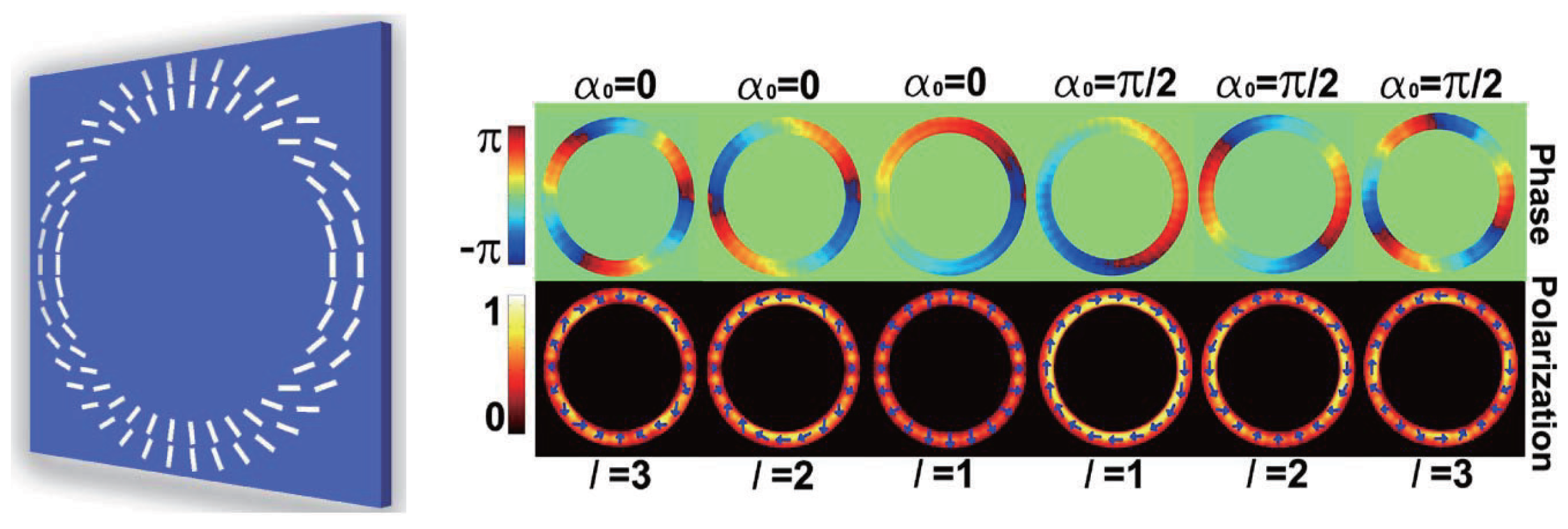
In Figure 9, two rings of slots are put on a gold film with thickness of 200 nm. The rotation angle of the slots satisfies . Thus, under the excitation of RCP light, according to Equation (9), the spatially variant factor in is . The generated OAM order is . The structure can be fabricated using electron-beam lithography [95].
3.5. Continuously Shaped Metasurfaces
The scatterers in the previous discussion provide discrete levels of abrupt phase shift by employing the geometric phase concept. In this section, we review several prototypes with continuous or quasi-continuous phase levels [87,88,96]. They generate OAM with high purity.
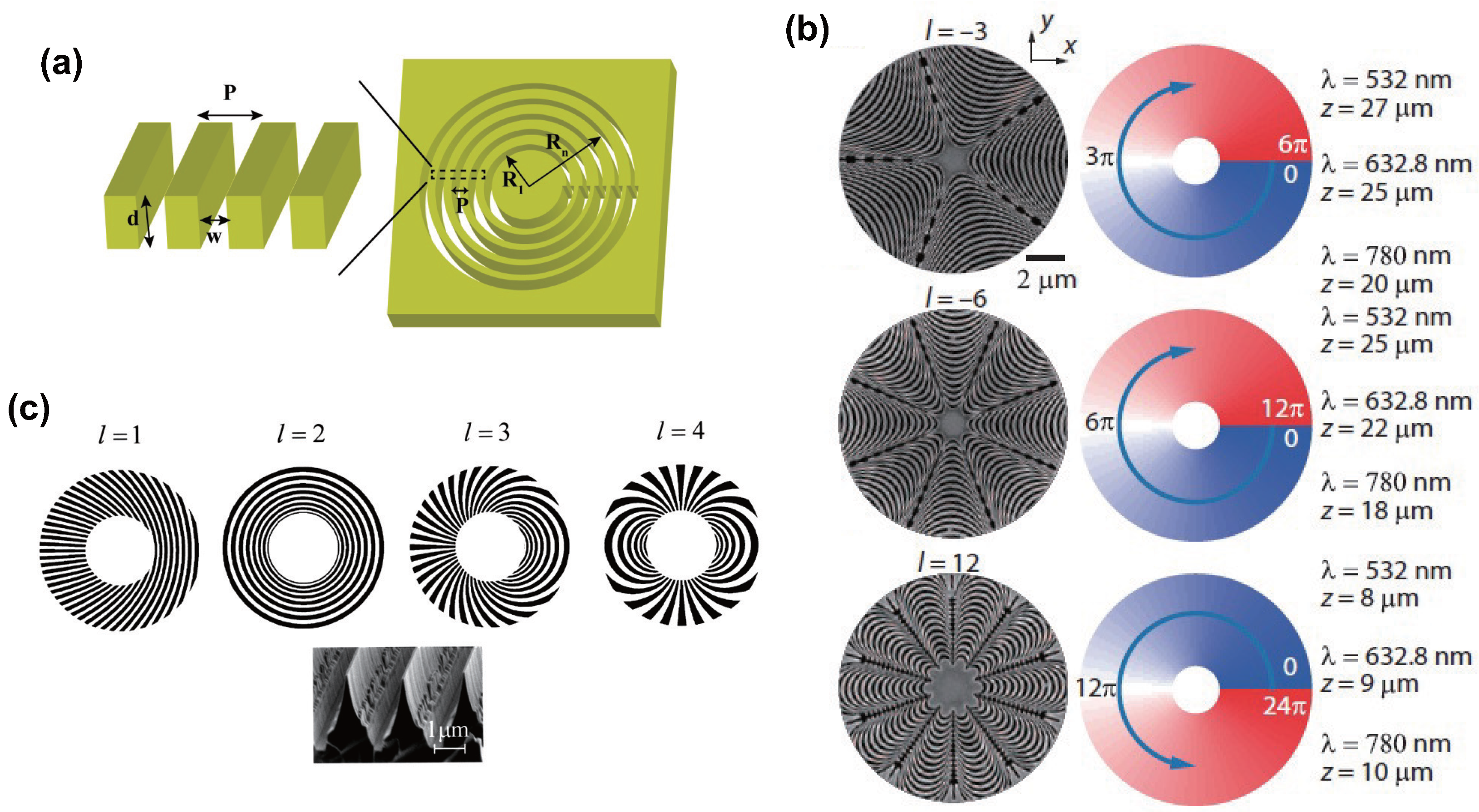
In Figure 10a, a metasurface is composed of annular apertures with smoothly changed widths. The phase shift comes not only from the geometric phase due to the varying aperture orientation but also from the plasmon retardation phase which is modulated by the aperture width. With the contribution of the two phases, arbitrary OAM orders can be generated. Under the incidence of circularly polarized wave, according to (9), the radially polarized component acquires a geometric phase of and the cross-circularly polarized one has a geometric phase of . To fabricate the metasurface sample, a 2-nm-thick Cr film and a 450-nm-thick silver film were subsequently deposited on a quartz substrate using magnetron sputtering. The annular apertures are then milled on the silver/Cr film through focused-iron beam lithography. Figure 10b shows the a pattern constructed from catenary-shaped atoms. The inclination angle for a single caternary gradually varies a total of from one end of the caternary to the other end. The induced geometric phase doubles the value of inclination value for the cross-circularly polarized output wave. By arranging the catenaries accordingly, OAM beams can be produced. Since this geometric phase does not depend on frequency, the design has a broadband response. The fabrication process of the caternaries is similar to that of the annular apertures in Figure 10a, except that a 120-nm-thick Au film was deposited instead of the 450-nm-thick silver film. The direction of the grating grooves in Figure 10c is designed to satisfy . It is illuminated by a RCP wave and the transmitted LCP wave carries an OAM of order l. The gratings were created by etching of a 500-µm-thick GaAs wafer through electron cyclotron resonance source (BCl3) to a depth of 2.5-µm.
3.6. Metasurfaces for Multiple OAM-Beam Generation
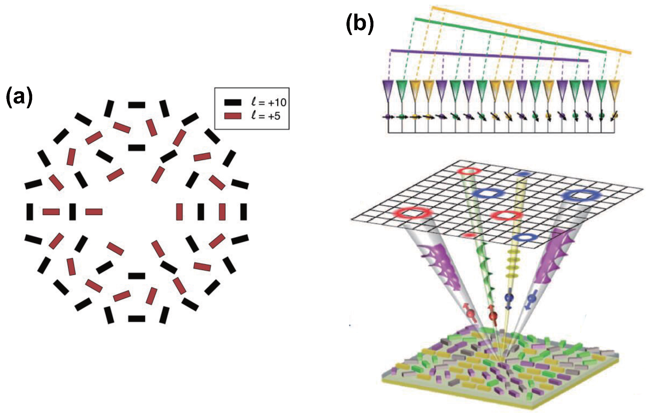
Figure 11 depicts two types of geometric-phase metasurfaces for multiple OAM-beam generation [90,97]. The metasurface in Figure 11a generates two collinear OAM beams. The dielectric nanofins forming the topological charges of and are interleaved each other. The dielectric nanofins consisted of TiO2 and were fabricated based on atomic layer deposition and electron beam lithography. In Figure 11b, the nanoantennas with different topological charge are interleaved randomly.
4. Holographic Metasurfaces for OAM Detection
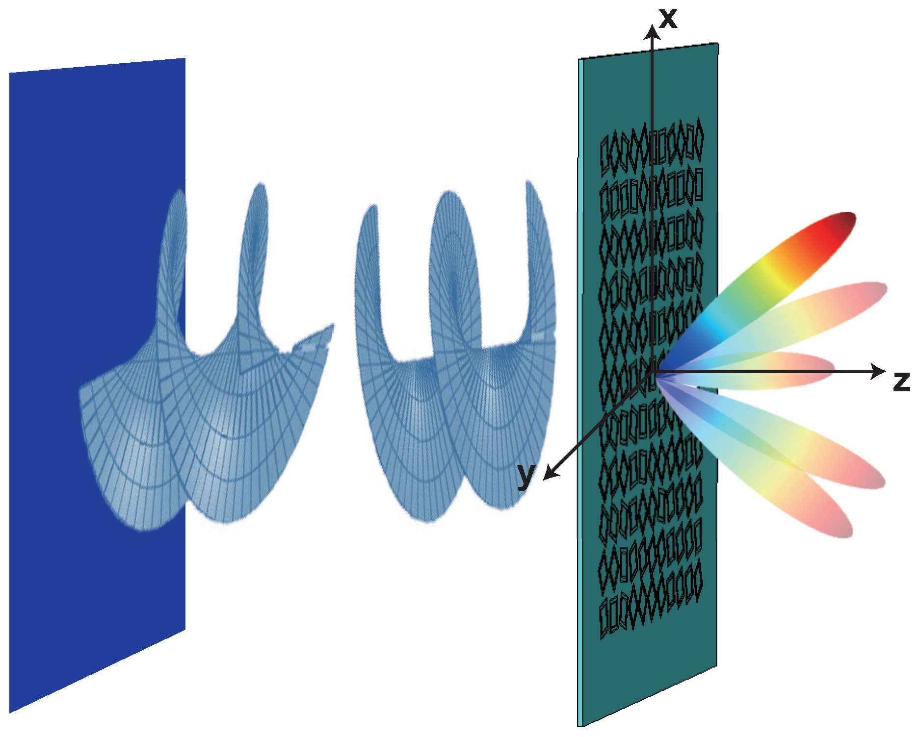
We adopt the holographic concept for the detection of multiple OAM-beam using a single metasurface [89]. The detection process is summarized in Figure 12. The metasurface converts the incident wave to multiple waves, only one of which is Gaussian. The radiation direction of the Gaussian wave is distinguishable according to the order of incident OAM. Consequently, by locating the Gaussian wave, the incident OAM can be conveniently determined.
The transmission function of the desired metasurface is given by (5). Then, the far-field response of the metasurface illuminated by an incident wave carrying OAM of order is calculated by doing the Fourier transform
Multiple waves with the OAM of order at the k-space position are observed. When , the beam is Gaussian and its beam axis is at . It is known that OAM wave has a singularity at its beam axis. Therefore, by examining the field intensity at the positions of , we can identify the gaussian beam, i.e., identify M. Then the incident OAM order can be determined.
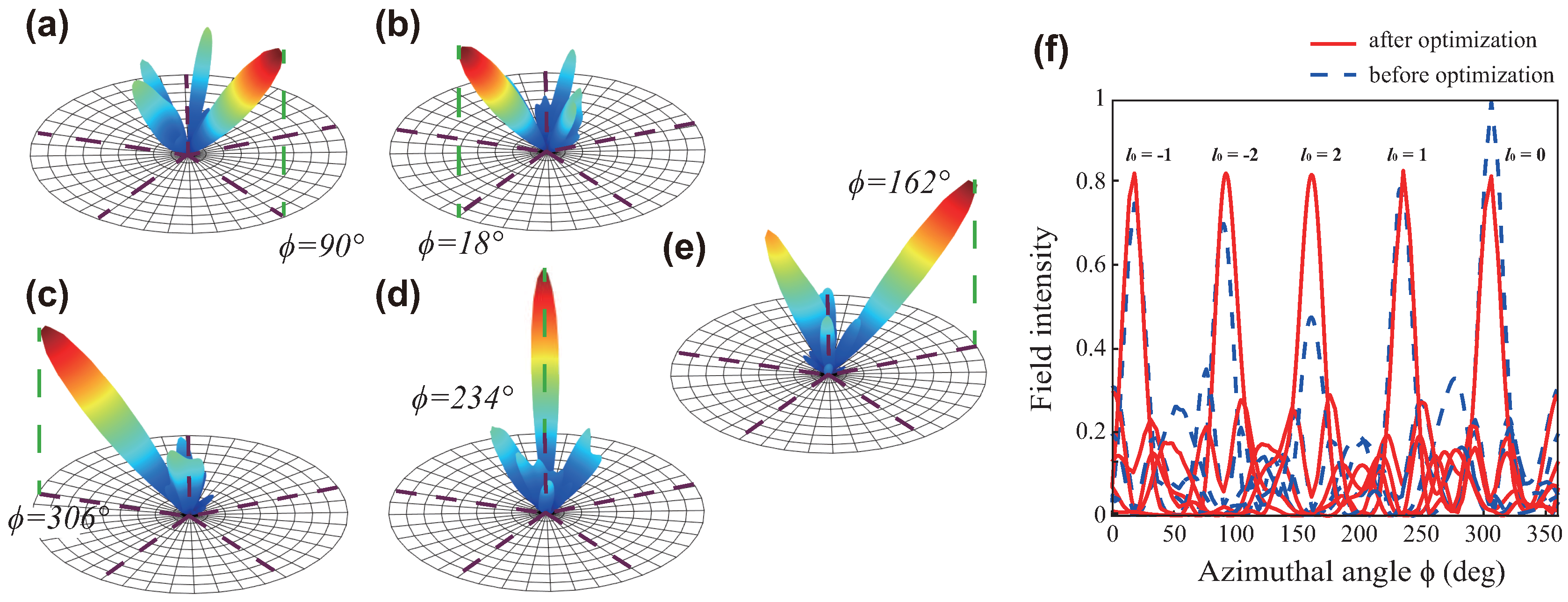
As a proof of concept, a five-beam case with at the directions of = 40° and = 90°, 18°, 306°, 234°, 162° is demonstrated. The calculated transmittance is implemented using the unit cell as shown in Figure 4a. Full-wave simulated radiation patterns are shown in Figure 13. It can be seen that the maximum radiation direction (axis of the gaussian beam) when is at = 40° and = 90°, 18°, 306°, 234°, 162°, respectively, which is as expected.
A modified transmission function is proposed to lower the side-lobe level:
We see an additional phase term in (11). This term rotates the mth beam and changes the interference status between the beam with other four beams. Therefore, by setting a proper value for , we can weaken the constructive interference between adjacent beams, which is the main reason for the high side lobes. The optimal solution for is . The comparison results after optimization are shown in Figure 13f. When , the field intensity at a desired location is increased. A general trend of lowered side-lobe level can also be observed. It can be noted that the intensity becomes lower for . One may break the constructive interference between two adjacent beams but result in an enhanced interference between one of the adjacent beam with the other adjacent beam on the other side. Hence, it is not possible to achieve improvements for all the five incident cases, but there has to be a trade off. Overall, we can observe suppressed side lobes and increased field intensities at desired locations.
5. Conclusions
In summary, we reviewed the research work on the geometric-phase based metasurfaces for OAM generation and detection. The metasurfaces achieve wavefront manipulation by the spin-induced geometric phase and show high flexibilities. Most importantly, they can be multifunctional. Besides the OAM generation and detection, they are designed for realizing beam multiplexing and demultiplexing and manipulating polarization. Therefore, the geometric-phase metasurfaces are promising candidates for practical applications of OAM beams.
Acknowledgments
This work was supported in part by the Research Grants Council of Hong Kong (GRF 716713, GRF 17207114, and GRF 17210815), NSFC 61271158, Hong Kong UGC AoE/P04/08, AOARD FA2386-17-1-0010, Hong Kong ITP/045/14LP, and Hundred Talents Program of Zhejiang University (No. 188020*194231701/208).
Author Contributions
Menglin L. N. Chen drafted the manusciprt. Li Jun Jiang and Wei. E. I. Sha revised and finalized the manuscript.
Conflicts of Interest
The authors declare no conflict of interest.
Abbreviations
The following abbreviations are used in this manuscript:
| OAM | Orbital angular momentum |
| EM | Electromagnetic |
| AM | Angular momentum |
| SAM | Spin angular momentum |
| LHCP | Left-handed circular polarization |
| RHCP | Right-handed circular polarization |
| LG | Laguerre-Gaussian |
| CGH | Computer generated hologram |
| SPP | Spiral phase plates |
| FSS | Frequency selective surface |
| RCP | Right circularly polarized |
| LCP | Left circularly polarized |
| SRR | Split-ring resonators |
| PEC | Perfect electric conductor |
| PMC | Perfect magnetic conductor |
| PCB | Printed circuit board |
| CSRR | Complementary split-ring resonators |
| LC | Inductor-capacitor |
References
- Bliokh, K.Y.; Bekshaev, A.Y.; Nori, F. Dual electromagnetism: Helicity, spin, momentum and angular momentum. New J. Phys. 2013, 15, 033126. [Google Scholar] [CrossRef]
- Gibson, G.; Courtial, J.; Padgett, M.J.; Vasnetsov, M.; Pas’ko, V.; Barnett, S.M.; Franke-Arnold, S. Free-space information transfer using light beams carrying orbital angular momentum. Opt. Express 2004, 12, 5448–5456. [Google Scholar] [CrossRef] [PubMed]
- Ren, Y.X.; Wang, Z.; Liao, P.C.; Li, L.; Xie, G.D.; Huang, H.; Zhao, Z.; Yan, Y.; Ahmed, N.; Willner, A.; et al. Experimental characterization of a 400 Gbit/s orbital angular momentum multiplexed free-space optical link over 120 m. Opt. Lett. 2016, 41, 622–625. [Google Scholar] [CrossRef] [PubMed]
- Willner, A.E.; Huang, H.; Yan, Y.; Ren, Y.; Ahmed, N.; Xie, G.; Bao, C.; Li, L.; Cao, Y.; Zhao, Z.; et al. Optical communications using orbital angular momentum beams. Adv. Opt. Photonics 2015, 7, 66–106. [Google Scholar] [CrossRef]
- Wang, J.; Yang, J.Y.; Fazal, I.M.; Ahmed, N.; Yan, Y.; Huang, H.; Ren, Y.X.; Yue, Y.; Dolinar, S.; Tur, M.; et al. Terabit free-space data transmission employing orbital angular momentum multiplexing. Nat. Photonics 2012, 6, 488–496. [Google Scholar] [CrossRef]
- Thide, B.; Then, H.; Sjoholm, J.; Palmer, K.; Bergman, J.; Carozzi, T.D.; Istomin, Y.N.; Ibragimov, N.H.; Khamitova, R. Utilization of photon orbital angular momentum in the low-frequency radio domain. Phys. Rev. Lett. 2007, 99, 087701. [Google Scholar] [CrossRef] [PubMed]
- Mahmouli, F.E.; Walker, S.D. 4-Gbps uncompressed video transmission over a 60-ghz orbital angular momentum wireless channel. IEEE Wirel. Commun. Lett. 2013, 2, 223–226. [Google Scholar] [CrossRef]
- Yan, Y.; Xie, G.D.; Lavery, M.P.J.; Huang, H.; Ahmed, N.; Bao, C.J.; Ren, Y.X.; Cao, Y.W.; Li, L.; Zhao, Z.; et al. High-capacity millimetre-wave communications with orbital angular momentum multiplexing. Nat. Commun. 2014, 5. [Google Scholar] [CrossRef] [PubMed]
- Hui, X.N.; Zheng, S.L.; Chen, Y.L.; Hu, Y.P.; Jin, X.F.; Chi, H.; Zhang, X.M. Multiplexed Millimeter Wave Communication with Dual Orbital Angular Momentum (OAM) Mode Antennas. Sci. Rep. 2015, 5, 10148. [Google Scholar] [CrossRef] [PubMed]
- Bozinovic, N.; Yue, Y.; Ren, Y.X.; Tur, M.; Kristensen, P.; Huang, H.; Willner, A.E.; Ramachandran, S. Terabit-Scale Orbital Angular Momentum Mode Division Multiplexing in Fibers. Science 2013, 340, 1545–1548. [Google Scholar] [CrossRef] [PubMed]
- Andersson, M.; Berglind, E.; Björk, G. Orbital angular momentum modes do not increase the channel capacity in communication links. New J. Phys. 2015, 17, 043040. [Google Scholar] [CrossRef]
- Xie, G.D.; Li, L.; Ren, Y.X.; Huang, H.; Yan, Y.; Ahmed, N.; Zhao, Z.; Lavery, M.P.J.; Ashrafi, N.; Ashrafi, S.; et al. Performance metrics and design considerations for a free-space optical orbital-angular-momentum-multiplexed communication link. Optica 2015, 2, 357–365. [Google Scholar] [CrossRef]
- Paterson, C. Atmospheric turbulence and orbital angular momentum of single photons for optical communication. Phys. Rev. Lett. 2005, 94, 153901. [Google Scholar] [CrossRef] [PubMed]
- Zhao, S.M.; Leach, J.; Gong, L.Y.; Ding, J.; Zheng, B.Y. Aberration corrections for free-space optical communications in atmosphere turbulence using orbital angular momentum states. Opt. Express 2012, 20, 452–461. [Google Scholar] [CrossRef] [PubMed]
- Oldoni, M.; Spinello, F.; Mari, E.; Parisi, G.; Someda, C.G.; Tamburini, F.; Romanato, F.; Ravanelli, R.A.; Coassini, P.; Thide, B. Space-Division Demultiplexing in Orbital-Angular-Momentum-Based MIMO Radio Systems. IEEE Trans. Antennas Propag. 2015, 63, 4582–4587. [Google Scholar] [CrossRef]
- Tamburini, F.; Anzolin, G.; Umbriaco, G.; Bianchini, A.; Barbieri, C. Overcoming the Rayleigh criterion limit with optical vortices. Phys. Rev. Lett. 2006, 97, 163903. [Google Scholar] [CrossRef] [PubMed]
- Liu, K.; Cheng, Y.Q.; Yang, Z.C.; Wang, H.Q.; Qin, Y.L.; Li, X. Orbital-Angular-Momentum-Based Electromagnetic Vortex Imaging. IEEE Antennas Wirel. Propag. Lett. 2015, 14, 711–714. [Google Scholar] [CrossRef]
- Grier, D.G. A revolution in optical manipulation. Nature 2003, 424, 810–816. [Google Scholar] [CrossRef] [PubMed]
- He, H.; Friese, M.E.J.; Heckenberg, N.R.; Rubinszteindunlop, H. Direct Observation of Transfer of Angular-Momentum to Absorptive Particles from a Laser-Beam with a Phase Singularity. Phys. Rev. Lett. 1995, 75, 826–829. [Google Scholar] [CrossRef] [PubMed]
- Simpson, N.B.; Dholakia, K.; Allen, L.; Padgett, M.J. Mechanical equivalence of spin and orbital angular momentum of light: an optical spanner. Opt. Lett. 1997, 22, 52–54. [Google Scholar] [CrossRef] [PubMed]
- Lavery, M.P.J.; Speirits, F.C.; Barnett, S.M.; Padgett, M.J. Detection of a Spinning Object Using Light’s Orbital Angular Momentum. Science 2013, 341, 537–540. [Google Scholar] [CrossRef] [PubMed]
- Dada, A.C.; Leach, J.; Buller, G.S.; Padgett, M.J.; Andersson, E. Experimental high-dimensional two-photon entanglement and violations of generalized Bell inequalities. Nat. Phys. 2011, 7, 677–680. [Google Scholar] [CrossRef]
- Leach, J.; Jack, B.; Romero, J.; Jha, A.K.; Yao, A.M.; Franke-Arnold, S.; Ireland, D.G.; Boyd, R.W.; Barnett, S.M.; Padgett, M.J. Quantum Correlations in Optical Angle-Orbital Angular Momentum Variables. Science 2010, 329, 662–665. [Google Scholar] [CrossRef] [PubMed]
- Ren, H.R.; Li, X.P.; Zhang, Q.M.; Gu, M. On-chip noninterference angular momentum multiplexing of broadband light. Science 2016, 352, 805–809. [Google Scholar] [CrossRef] [PubMed]
- Mei, S.T.; Huang, K.; Liu, H.; Qin, F.; Mehmood, M.Q.; Xu, Z.J.; Hong, M.H.; Zhang, D.H.; Teng, J.H.; Danner, A.; et al. On-chip discrimination of orbital angular momentum of light with plasmonic nanoslits. Nanoscale 2016, 8, 2227–2233. [Google Scholar] [CrossRef] [PubMed]
- Molina-Terriza, G.; Torres, J.P.; Torner, L. Twisted photons. Nat. Phys. 2007, 3, 305–310. [Google Scholar] [CrossRef]
- Vaziri, A.; Weihs, G.; Zeilinger, A. Superpositions of the orbital angular momentum for applications in quantum experiments. J. Opt. B 2002, 4, S47–S51. [Google Scholar] [CrossRef]
- Allen, L.; Beijersbergen, M.W.; Spreeuw, R.J.C.; Woerdman, J.P. Orbital Angular-Momentum of Light and the Transformation of Laguerre-Gaussian Laser Modes. Phys. Rev. A 1992, 45, 8185–8189. [Google Scholar] [CrossRef] [PubMed]
- Bazhenov, V.Y.; Vasnetsov, M.V.; Soskin, M.S. Laser-Beams with Screw Dislocations in Their Wave-Fronts. JETP Lett. 1990, 52, 429–431. [Google Scholar]
- Beijersbergen, M.W.; Allen, L.; Vanderveen, H.E.L.O.; Woerdman, J.P. Astigmatic Laser Mode Converters and Transfer of Orbital Angular-Momentum. Opt. Commun. 1993, 96, 123–132. [Google Scholar] [CrossRef]
- Beijersbergen, M.; Coerwinkel, R.; Kristensen, M.; Woerdman, J. Helical-wavefront laser beams produced with a spiral phaseplate. Opt. Commun. 1994, 112, 321–327. [Google Scholar] [CrossRef]
- Marrucci, L.; Manzo, C.; Paparo, D. Optical spin-to-orbital angular momentum conversion in inhomogeneous anisotropic media. Phys. Rev. Lett. 2006, 96, 163905. [Google Scholar] [CrossRef] [PubMed]
- Mohammadi, S.M.; Daldorff, L.K.S.; Bergman, J.E.S.; Karlsson, R.L.; Thide, B.; Forozesh, K.; Carozzi, T.D.; Isham, B. Orbital Angular Momentum in Radio-A System Study. IEEE Trans. Antennas Propag. 2010, 58, 565–572. [Google Scholar] [CrossRef]
- Zheng, S.L.; Hui, X.N.; Jin, X.F.; Chi, H.; Zhang, X.M. Transmission Characteristics of a Twisted Radio Wave Based on Circular Traveling-Wave Antenna. IEEE Trans. Antennas Propag. 2015, 63, 1530–1536. [Google Scholar] [CrossRef]
- Barbuto, M.; Trotta, F.; Bilotti, F.; Toscano, A. Circular Polarized Patch Antenna Generating Orbital Angular Momentum. Prog. Electromagn. Res. 2014, 148, 23–30. [Google Scholar] [CrossRef]
- Yu, N.F.; Capasso, F. Flat optics with designer metasurfaces. Nat. Mater. 2014, 13, 139–150. [Google Scholar] [CrossRef] [PubMed]
- Yu, N.F.; Genevet, P.; Kats, M.A.; Aieta, F.; Tetienne, J.P.; Capasso, F.; Gaburro, Z. Light Propagation with Phase Discontinuities: Generalized Laws of Reflection and Refraction. Science 2011, 334, 333–337. [Google Scholar] [CrossRef] [PubMed]
- Genevet, P.; Yu, N.F.; Aieta, F.; Lin, J.; Kats, M.A.; Blanchard, R.; Scully, M.O.; Gaburro, Z.; Capasso, F. Ultra-thin plasmonic optical vortex plate based on phase discontinuities. Appl. Phys. Lett. 2012, 100, 013101. [Google Scholar] [CrossRef]
- Yu, N.F.; Genevet, P.; Aieta, F.; Kats, M.A.; Blanchard, R.; Aoust, G.; Tetienne, J.P.; Gaburro, Z.; Capasso, F. Flat optics: Controlling wavefronts with optical antenna metasurfaces. IEEE J. Sel. Top. Quantum Electron. 2013, 19. [Google Scholar] [CrossRef]
- Munk, B. Frequency Selective Surfaces: Theory and Design; John Wiley: New York, NY, USA, 2000. [Google Scholar]
- Kou, N.; Yu, S.X.; Li, L. Generation of high-order Bessel vortex beam carrying orbital angular momentum using multilayer amplitude-phase-modulated surfaces in radiofrequency domain. Appl. Phys. Express 2017, 10, 016701. [Google Scholar] [CrossRef]
- Pfeiffer, C.; Grbic, A. Metamaterial Huygens’ Surfaces: Tailoring Wave Fronts with Reflectionless Sheets. Phys. Rev. Lett. 2013, 110, 197401. [Google Scholar] [CrossRef] [PubMed]
- Niv, A.; Biener, G.; Kleiner, V.; Hasman, E. Spiral phase elements obtained by use of discrete space-variant subwavelength gratings. Opt. Commun. 2005, 251, 306–314. [Google Scholar] [CrossRef]
- Turnbull, G.A.; Robertson, D.A.; Smith, G.M.; Allen, L.; Padgett, M.J. The generation of free-space Laguerre-Gaussian modes at millimetre-wave frequencies by use of a spiral phaseplate. Opt. Commun. 1996, 127, 183–188. [Google Scholar] [CrossRef]
- Kotlyar, V.V.; Almazov, A.A.; Khonina, S.N.; Soifer, V.A.; Elfstrom, H.; Turunen, J. Generation of phase singularity through diffracting a plane or Gaussian beam by a spiral phase plate. J. Opt. Soc. Am. A 2005, 22, 849–861. [Google Scholar] [CrossRef]
- Hui, X.N.; Zheng, S.L.; Hu, Y.P.; Xu, C.; Jin, X.F.; Chi, H.; Zhang, X.M. Ultralow Reflectivity Spiral Phase Plate for Generation of Millimeter-wave OAM Beam. IEEE Antennas Wirel. Propag. Lett. 2015, 14, 966–969. [Google Scholar] [CrossRef]
- Cheng, L.; Hong, W.; Hao, Z.C. Generation of Electromagnetic Waves with Arbitrary Orbital Angular Momentum Modes. Sci. Rep. 2014, 4. [Google Scholar] [CrossRef] [PubMed]
- Sun, J.B.; Wang, X.; Xu, T.B.Y.; Kudyshev, Z.A.; Cartwright, A.N.; Litchinitser, N.M. Spinning Light on the Nanoscale. Nano Lett. 2014, 14, 2726–2729. [Google Scholar] [CrossRef] [PubMed]
- Carpentier, A.V.; Michinel, H.; Salgueiro, J.R.; Olivieri, D. Making optical vortices with computer-generated holograms. Am. J. Phys. 2008, 76, 916–921. [Google Scholar] [CrossRef]
- Heckenberg, N.R.; Mcduff, R.; Smith, C.P.; White, A.G. Generation of Optical-Phase Singularities by Computer-Generated Holograms. Opt. Lett. 1992, 17, 221–223. [Google Scholar] [CrossRef] [PubMed]
- Arlt, J.; Dholakia, K.; Allen, L.; Padgett, M.J. The production of multiringed Laguerre-Gaussian modes by computer-generated holograms. J. Mod. Opt. 1998, 45, 1231–1237. [Google Scholar] [CrossRef]
- Moreno, I.; Davis, J.A.; Pascoguin, B.M.L.; Mitry, M.J.; Cottrell, D.M. Vortex sensing diffraction gratings. Opt. Lett. 2009, 34, 2927–2929. [Google Scholar] [CrossRef] [PubMed]
- Liu, K.; Liu, H.Y.; Qin, Y.L.; Cheng, Y.Q.; Wang, S.N.; Li, X.; Wang, H.Q. Generation of OAM Beams Using Phased Array in the Microwave Band. IEEE Trans. Antennas Propag. 2016, 64, 3850–3857. [Google Scholar] [CrossRef]
- Comite, D.; Valerio, G.; Albani, M.; Galli, A.; Casaletti, M.; Ettorre, M. Exciting Vorticity through Higher Order Bessel Beams with a Radial-Line Slot-Array Antenna. IEEE Trans. Antennas Propag. 2017, 65, 2123–2128. [Google Scholar] [CrossRef]
- Xu, B.J.; Wu, C.; Wei, Z.Y.; Fan, Y.C.; Li, H.Q. Generating an orbital-angular-momentum beam with a metasurface of gradient reflective phase. Opt. Mater. Express 2016, 6, 3940–3945. [Google Scholar] [CrossRef]
- Yu, S.X.; Li, L.; Shi, G.M.; Zhu, C.; Shi, Y. Generating multiple orbital angular momentum vortex beams using a metasurface in radio frequency domain. Appl. Phys. Lett. 2016, 108, 241901. [Google Scholar] [CrossRef]
- Wang, L.Y.; Shi, H.Y.; Zhu, S.T.; Li, J.X.; Zhang, A.X.; Li, L.M. Generation of multiple modes microwave vortex beams using tunable metasurfacee. In Proceedings of the 7th IEEE International Symposium on Microwave, Antenna, Propagation and EMC Technologies, Xi’an, China, 24–27 October 2017; pp. 379–381. [Google Scholar]
- Maccalli, S.; Pisano, G.; Colafrancesco, S.; Maffei, B.; Ng, M.W.R.; Gray, M. Q-plate for millimeter-wave orbital angular momentum manipulation. Appl. Opt. 2013, 52, 635–639. [Google Scholar] [CrossRef] [PubMed]
- Cardano, F.; Karimi, E.; Slussarenko, S.; Marrucci, L.; de Lisio, C.; Santamato, E. Polarization pattern of vector vortex beams generated by q-plates with different topological charges. Appl. Opt. 2012, 51, C1–C6. [Google Scholar] [CrossRef] [PubMed]
- Bliokh, K.Y.; Rodriguez-Fortuno, F.J.; Nori, F.; Zayats, A.V. Spin-orbit interactions of light. Nat. Photonics 2015, 9, 796–808. [Google Scholar] [CrossRef] [Green Version]
- Karimi, E.; Piccirillo, B.; Nagali, E.; Marrucci, L.; Santamato, E. Efficient generation and sorting of orbital angular momentum eigenmodes of light by thermally tuned q-plates. Appl. Phys. Lett. 2009, 94, 231124. [Google Scholar] [CrossRef]
- Piccirillo, B.; D’Ambrosio, V.; Slussarenko, S.; Marrucci, L.; Santamato, E. Photon spin-to-orbital angular momentum conversion via an electrically tunable q-plate. Appl. Phys. Lett. 2010, 97, 241104. [Google Scholar] [CrossRef]
- Kang, M.; Feng, T.H.; Wang, H.T.; Li, J.S. Wave front engineering from an array of thin aperture antennas. Opt. Express 2012, 20, 15882–15890. [Google Scholar] [CrossRef] [PubMed]
- Xu, H.X.; Liu, H.; Ling, X.; Sun, Y.; Yuan, F. Broadband Vortex Beam Generation Using Multimode Pancharatnam-Berry Metasurface. IEEE Trans. Antennas Propag. 2017, 65, 7378–7382. [Google Scholar] [CrossRef]
- Karimi, E.; Schulz, S.A.; De Leon, I.; Qassim, H.; Upham, J.; Boyd, R.W. Generating optical orbital angular momentum at visible wavelengths using a plasmonic metasurface. Light Sci. Appl. 2014, 3, e167. [Google Scholar] [CrossRef]
- Tan, Q.L.; Guo, Q.H.; Liu, H.C.; Huang, G.; Zhang, S. Controlling the plasmonic orbital angular momentum by combining the geometric and dynamic phases. Nanoscale 2017, 9, 4944–4949. [Google Scholar] [CrossRef] [PubMed]
- Li, G.X.; Kang, M.; Chen, S.M.; Zhang, S.; Pun, E.Y.B.; Cheah, K.W.; Li, J.S. Spin-enabled plasmonic metasurfaces for manipulating orbital angular momentum of light. Nano Lett. 2013, 13, 4148–4151. [Google Scholar] [CrossRef] [PubMed]
- Mohammadi, S.M.; Daldorff, L.K.S.; Forozesh, K.; Thide, B.; Bergman, J.E.S.; Isham, B.; Karlsson, R.; Carozzi, T.D. Orbital angular momentum in radio: Measurement methods. Radio Sci. 2010, 45. [Google Scholar] [CrossRef]
- Schulze, C.; Dudley, A.; Flamm, D.; Duparre, M.; Forbes, A. Measurement of the orbital angular momentum density of light by modal decomposition. New J. Phys. 2013, 15, 073025. [Google Scholar] [CrossRef]
- Hui, X.N.; Zheng, S.L.; Zhang, W.T.; Jin, X.F.; Chi, H.; Zhang, X.M. Local topological charge analysis of electromagnetic vortex beam based on empirical mode decomposition. Opt. Express 2016, 24, 5423–5430. [Google Scholar] [CrossRef] [PubMed]
- Zhang, C.; Lu, M. Detecting the orbital angular momentum of electro-magnetic waves using virtual rotational antenna. Sci. Rep. 2017, 7, 4585. [Google Scholar] [CrossRef] [PubMed]
- Courtial, J.; Dholakia, K.; Robertson, D.A.; Allen, L.; Padgett, M.J. Measurement of the rotational frequency shift imparted to a rotating light beam possessing orbital angular momentum. Phys. Rev. Lett. 1998, 80, 3217–3219. [Google Scholar] [CrossRef]
- Allen, L.; Babiker, M.; Power, W.L. Azimuthal Doppler-Shift in Light-Beams with Orbital Angular-Momentum. Opt. Commun. 1994, 112, 141–144. [Google Scholar] [CrossRef]
- Genevet, P.; Lin, J.; Kats, M.A.; Capasso, F. Holographic detection of the orbital angular momentum of light with plasmonic photodiodes. Nat. Commun. 2012, 3, 1278. [Google Scholar] [CrossRef] [PubMed] [Green Version]
- Tamburini, F.; Mari, E.; Sponselli, A.; Thide, B.; Bianchini, A.; Romanato, F. Encoding many channels on the same frequency through radio vorticity: first experimental test. New J. Phys. 2012, 14, 033001. [Google Scholar] [CrossRef]
- Mair, A.; Vaziri, A.; Weihs, G.; Zeilinger, A. Entanglement of the orbital angular momentum states of photons. Nature 2001, 412, 313–316. [Google Scholar] [CrossRef] [PubMed]
- Luo, W.J.; Xiao, S.Y.; He, Q.; Sun, S.L.; Zhou, L. Photonic Spin Hall Effect with Nearly Efficiency. Adv. Opt. Mater. 2015, 3, 1102–1108. [Google Scholar] [CrossRef]
- Georgi, P.; Schlickriede, C.; Li, G.X.; Zhang, S.; Zentgraf, T. Rotational Doppler shift induced by spin-orbit coupling of light at spinning metasurfaces. Optica 2017, 4, 1000–1005. [Google Scholar] [CrossRef]
- Bouchard, F.; De Leon, I.; Schulz, S.A.; Upham, J.; Karimi, E.; Boyd, R.W. Optical spin-to-orbital angular momentum conversion in ultra-thin metasurfaces with arbitrary topological charges. Appl. Phys. Lett. 2014, 105, 101905. [Google Scholar] [CrossRef]
- Wang, W.; Li, Y.; Guo, Z.Y.; Li, R.Z.; Zhang, J.R.; Zhang, A.J.; Qu, S.L. Ultra-thin optical vortex phase plate based on the metasurface and the angular momentum transformation. J. Opt. 2015, 17, 045102. [Google Scholar] [CrossRef]
- Jin, J.J.; Luo, J.; Zhang, X.H.; Gao, H.; Li, X.; Pu, M.B.; Gao, P.; Zhao, Z.Y.; Luo, X.G. Generation and detection of orbital angular momentum via metasurface. Sci. Rep. 2016, 6. [Google Scholar] [CrossRef] [PubMed]
- Zelenchuk, D.; Fusco, V. Split-Ring FSS Spiral Phase Plate. IEEE Antennas Wirel. Propag. Lett. 2013, 12, 284–287. [Google Scholar] [CrossRef] [Green Version]
- Tan, Y.H.; Li, L.L.; Ruan, H.X. An Efficient Approach to Generate Microwave Vector-Vortex Fields Based on Metasurface. Microw. Opt. Technol. Lett. 2015, 57, 1708–1713. [Google Scholar] [CrossRef]
- Chen, M.L.N.; Jiang, L.J.; Sha, W.E.I. Artificial perfect electric conductor-perfect magnetic conductor anisotropic metasurface for generating orbital angular momentum of microwave with nearly perfect conversion efficiency. J. Appl. Phys. 2016, 119, 064506. [Google Scholar] [CrossRef]
- Chen, M.L.L.N.; Jiang, L.J.; Sha, W.E.I. Ultrathin Complementary Metasurface for Orbital Angular Momentum Generation at Microwave Frequencies. IEEE Trans. Antennas Propag. 2017, 65, 396–400. [Google Scholar] [CrossRef]
- Li, Y.; Li, X.; Chen, L.W.; Pu, M.B.; Jin, J.J.; Hong, M.H.; Luo, X.G. Orbital Angular Momentum Multiplexing and Demultiplexing by a Single Metasurface. Adv. Opt. Mater. 2017, 5. [Google Scholar] [CrossRef]
- Guo, Y.H.; Pu, M.B.; Zhao, Z.Y.; Wang, Y.Q.; Jin, J.J.; Gao, P.; Li, X.; Ma, X.L.; Luo, X.G. Merging Geometric Phase and Plasmon Retardation Phase in Continuously Shaped Metasurfaces for Arbitrary Orbital Angular Momentum Generation. ACS Photonics 2016, 3, 2022–2029. [Google Scholar] [CrossRef]
- Pu, M.B.; Li, X.; Ma, X.L.; Wang, Y.Q.; Zhao, Z.Y.; Wang, C.T.; Hu, C.G.; Gao, P.; Huang, C.; Ren, H.R.; et al. Catenary optics for achromatic generation of perfect optical angular momentum. Sci. Adv. 2015, 1, e1500396. [Google Scholar] [CrossRef] [PubMed]
- Chen, M.; Jiang, L.J.; Wei, E. Detection of Orbital Angular Momentum with Metasurface at Microwave Band. IEEE Antennas Wirel. Propag. Lett. 2017. [Google Scholar] [CrossRef]
- Devlin, R.C.; Ambrosio, A.; Wintz, D.; Oscurato, S.L.; Zhu, A.Y.; Khorasaninejad, M.; Oh, J.; Maddalena, P.; Capasso, F. Spin-to-orbital angular momentum conversion in dielectric metasurfaces. Opt. Express 2017, 25, 377–393. [Google Scholar] [CrossRef] [PubMed]
- Dang, X.W.; Li, M.K.; Yang, F.; Xu, S.H. Quasi-periodic array modeling using reduced basis from elemental array. IEEE J. Multiscale Multiphys. Comput. Tech. 2017, 2, 202–208. [Google Scholar] [CrossRef]
- Chen, S.M.; Cai, Y.; Li, G.X.; Zhang, S.; Cheah, K.W. Geometric metasurface fork gratings for vortex-beam generation and manipulation. Laser Photonics Rev. 2016, 10, 322–326. [Google Scholar] [CrossRef]
- Kang, M.; Chen, J.; Wang, X.L.; Wang, H.T. Twisted vector field from an inhomogeneous and anisotropic metamaterial. J. Opt. Soc. Am. B 2012, 29, 572–576. [Google Scholar] [CrossRef]
- Zhao, Z.; Wang, J.; Li, S.H.; Willner, A.E. Metamaterials-based broadband generation of orbital angular momentum carrying vector beams. Opt. Lett. 2013, 38, 932–934. [Google Scholar] [CrossRef] [PubMed]
- Wang, J.; Du, J. Plasmonic and dielectric metasurfaces: Design, fabrication and applications. Appl. Sci. 2016, 6, 239. [Google Scholar] [CrossRef]
- Biener, G.; Niv, A.; Kleiner, V.; Hasman, E. Formation of helical beams by use of Pancharatnam-Berry phase optical elements. Opt. Lett. 2002, 27, 1875–1877. [Google Scholar] [CrossRef] [PubMed]
- Maguid, E.; Yulevich, I.; Veksler, D.; Kleiner, V.; Brongersma, M.L.; Hasman, E. Photonic spin-controlled multifunctional shared-aperture antenna array. Science 2016, 352, 1202–1206. [Google Scholar] [CrossRef] [PubMed]
Figure 1.
Schematic pattern of the perfect electric conductor (PEC)-perfect magnetic conductor (PMC) anisotropic metasurface for orbital angular momentum (OAM) generation. With a nearly 100% conversion efficiency, the metasurface perfectly converts a left (right) circularly polarized plane wave carrying zero OAM to a right (left) circularly polarized vortex beam carrying OAM: (a) Top view of the whole metasurface; (b,c) A scatterer in the metasurface. The scatterer is composed of artificial PEC (purple) and PMC (blue and red) surfaces. The period of the scatterer is mm. The permittivity and thickness of the dielectric substrate are set to , mm and mm. For the artificial PEC surface (top-right inset), the width and gap for the strip is mm and mm, respectively. For the mushroom-based artificial PMC surface (bottom-right inset), the square patch size is mm. A metallic via with the radius of mm and height of mm connects the patch to the ground plane. Reproduced with permission from [84], Copyright AIP Publishing LLC, 2016.

Figure 2.
The amplitude and phase distributions of reflected electric fields from the PEC-PMC metasurface at a transverse plane mm: (a) Amplitude; (b) Phase. Reproduced with permission from [84], Copyright AIP Publishing LLC, 2016.
Figure 2.
The amplitude and phase distributions of reflected electric fields from the PEC-PMC metasurface at a transverse plane mm: (a) Amplitude; (b) Phase. Reproduced with permission from [84], Copyright AIP Publishing LLC, 2016.

Figure 3.
The amplitude and phase distributions of reflected electric fields from the discrete PEC-PMC metasurface. For the generation of OAM of order −2, (a) amplitude; (b) phase at a transverse plane mm. For the generation of OAM of order −4, (c) amplitude; (d) phase at a transverse plane mm. Reproduced with permission from [84], Copyright AIP Publishing LLC, 2016.

Figure 4.
Schematic and the response of the proposed unit cell: (a) Schematic; (b) Equivalent circuit model of one pair of complementary split-ring resonators (CSRRs) and simulated . The purple and green curves are obtained by the translation of the original blue (magnitude) and red (phase) curves. The distance between the two layers is h = 1.25 mm. Characteristic impedance of free space is . The capacitance and inductance are pF and nH; (c) Full-wave simulation results. The period of the unit cell is 7 × 7 mm2. Side lengths of the two types of square CSRRs are mm and mm. The length of the gap is mm. The width of the slots is mm. Reproduced with permission from [85], Copyright IEEE, 2017.

Figure 5.
Geometric structure of the metasurface. Topological charge is (a) ; (b) . The radius of the inner ring is mm and that of the outer ring is mm. Reproduced with permission from [85], Copyright IEEE, 2017.
Figure 5.
Geometric structure of the metasurface. Topological charge is (a) ; (b) . The radius of the inner ring is mm and that of the outer ring is mm. Reproduced with permission from [85], Copyright IEEE, 2017.

Figure 6.
Amplitude and phase distributions of the cross-circularly polarized component of electric field at a transverse plane of mm calculated from (a) the equivalent dipole model with the aperture in Figure 5a; (b) the equivalent dipole model with the aperture in Figure 5b; (c) the full-wave simulation with the aperture in Figure 5a; (d) the full-wave simulation with the aperture in Figure 5b. Reproduced with permission from [85], Copyright IEEE, 2017.

Figure 7.
(a) Phase distribution and the scanning electron images of metasurface fork gratings with topological charge of ; The plasmonic metasurfaces are fabricated on an 80-nm thick aluminum thin film by using focus ion beam method, consists of spatially variant nanoslits with a size of ∼50 nm by 210 nm. Scale bar: 3 µm. Reproduced with permission from [92], Copyright WILEY-VCH Verlag GmbH & Co. KGaA, Weinheim, 2016; (b) Schematics of off-axis incidence multi-OAM multiplexer and off-axis multi-OAM demultiplexer. Reproduced with permission from [86], Copyright WILEY-VCH Verlag GmbH & Co. KGaA, Weinheim, 2016.

Figure 8.
Geometry of a one-dimensional inhomogeneous anisotropic metamaterial composed of 10 rectangular holes with the orientation changed stepwisely from 0 to . The inset is the geometry of the unit cell that is a square metal slab punched into a rectangular hole. Reproduced with permission from [93], Copyright The Optical Society, 2012.

Figure 9.
Schematic structure of metamaterials for generating OAM-carrying vector beams and the spatial distributions of phase and polarization of generated OAM-carrying vector beams (, right circularly polarized (RCP) input beam). Reproduced with permission from [94], Copyright The Optical Society, 2013.

Figure 10.
(a) The metasurface is constructed by drilling a silver film with multiple periods of annular rings, whose radius is defined as , where n and P denote the number and the period of the apertures. The annular apertures can be taken as two-dimensional extensions of a set of nanoslits with spatially varying orientation. Reproduced with permission from [87], Copyright American Chemical Society, 2016; (b) OAM generators based on catenary arrays. The topological charges from up to bottom are −3, −6, and 12 (), respectively. The first column represents the scanning electron microscopy (SEM) images of the fabricated samples. The second column shows the spiral phase profiles. Reproduced with permission from [88], Copyright The American Association for the Advancement of Science, 2015; (c) Top, geometry of the subwavelength gratings for four topological charges. Bottom, image of a typical grating profile taken with a scanning-electron microscope. Reproduced with permission from [96], Copyright Optical Society of America, 2002.

Figure 11.
(a) Schematic of the nanofins azimuthal distribution in the inner part of metasurface device with interleaved patterns that generate collinear beams having topological charges and . The device has a 500 µm diameter and contains more than 700 interleaved radial rows of nanofins. Reproduced with permission from [90], Copyright Optical Society of America, 2017; (b) Schematic of shared-aperture concepts using interleaved 1D phased arrays and the schematic far-field intensity distribution of wavefronts with positive (red) and negative (blue) helicities. Reproduced with permission from [97], Copyright The American Association for the Advancement of Science, 2016.

Figure 12.
Schematic representation of multiple OAM-beam detection by a single metasurface. Reproduced with permission from [89], Copyright IEEE, 2017.
Figure 12.
Schematic representation of multiple OAM-beam detection by a single metasurface. Reproduced with permission from [89], Copyright IEEE, 2017.

Figure 13.
Full-wave simulated far-field power patterns when the incident wave carries OAM of order (a) −2; (b) −1; (c) 0; (d) 1; (e) 2. (f) Original and optimized far-field power patterns at = 40° for the five cases (a–e). Reproduced with permission from [89], Copyright IEEE, 2017.
Figure 13.
Full-wave simulated far-field power patterns when the incident wave carries OAM of order (a) −2; (b) −1; (c) 0; (d) 1; (e) 2. (f) Original and optimized far-field power patterns at = 40° for the five cases (a–e). Reproduced with permission from [89], Copyright IEEE, 2017.

© 2018 by the authors. Licensee MDPI, Basel, Switzerland. This article is an open access article distributed under the terms and conditions of the Creative Commons Attribution (CC BY) license (http://creativecommons.org/licenses/by/4.0/).
Share and Cite
MDPI and ACS Style
Chen, M.L.N.; Jiang, L.J.; Sha, W.E.I. Orbital Angular Momentum Generation and Detection by Geometric-Phase Based Metasurfaces. Appl. Sci. 2018, 8, 362. https://doi.org/10.3390/app8030362
AMA Style
Chen MLN, Jiang LJ, Sha WEI. Orbital Angular Momentum Generation and Detection by Geometric-Phase Based Metasurfaces. Applied Sciences. 2018; 8(3):362. https://doi.org/10.3390/app8030362
Chicago/Turabian StyleChen, Menglin L. N., Li Jun Jiang, and Wei E. I. Sha. 2018. "Orbital Angular Momentum Generation and Detection by Geometric-Phase Based Metasurfaces" Applied Sciences 8, no. 3: 362. https://doi.org/10.3390/app8030362
Note that from the first issue of 2016, this journal uses article numbers instead of page numbers. See further details here.