1. Introduction
The effort analysis of structural elements made of concrete using different types of reinforcement is the subject of various studies. These studies differ in scope, scale, and detail degree of analysis. Detailed experimental, analytical or numerical analyses were generally made for single structural elements. For example, the latest investigations on beams were presented in [
1,
2]. The analysis of steel and concrete composite shear walls under static compression was presented in [
3] and under seismic action in [
4]. The experimental and numerical analysis of the concrete circular plates with steel fibers reinforcement under impact load was presented in [
5]. The latest analytical and experimental load capacities investigations regarding the new concept of composite steel-reinforced concrete floor slab, was presented in [
6]. A numerical analysis of reinforcement concrete frame corners under an opening bending moment taking into account the assumed loading time was presented in [
7]. In turn, analyses of complex building structures were conducted at a generalized level, which showed a global effort of the construction. The numerical analyses of multistory buildings behavior under exceptional loads were presented in [
8,
9].
In many studies, the nonlinear analysis of the reinforced concrete structural elements were provided on the basis finite element method using existing software. The non-linear analysis of the shear failure mechanism of reinforced concrete beams was presented in [
10,
11]. The nonlinear analysis carried out a using numerical algorithm for the reinforced concrete shells under static and dynamic loading were presented in [
12]. The numerical analysis including material and geometrical nonlinearity with the influence of shear strength complementary mechanism for the reinforced concrete beams and frame were presented in [
13].
A load capacity analysis technique for a structural system was developed using the finite difference method, and the dynamic relaxation method (DRM) was applied to solve the nonlinear equilibrium equations. In this method, the problem can be reduced to analysis of a pseudo-dynamic process by considering critical damping as an aperiodic motion that approaches the equilibrium state under the acting load. The solution to this problem can be obtained using an iterative process with pseudo-time steps. The DRM is used to analyze highly nonlinear problems [
14,
15,
16]. Rezaiee-Pajand and Alamatian [
17] proposed further modifications in order to improve the convergence and accuracy of the solutions. Several practical applications of the DRM for structures were presented by Rezaiee-Pajand and Sarafrazi [
18], Bel Hadj Ali et al. [
19], and Barnes et al. [
20].
The arc-length parameter on the equilibrium path was introduced to the proposed numerical procedure to increase the efficiency of the method. This is referred to as the arc-length method, and it simultaneously determines the displacements and load parameter by tracing the equilibrium path that contains the local singular points. Subsequent developments and interpretations of the arc-length method were presented by de Borst et al. [
21], among others. A combination of the dynamic relaxation and arc-length methods was presented by Pasqualino [
22]. This was then applied to practical analysis of structural members by Ramesh and Krishnamoorthy [
23] as well as Pasqualino and Estefen [
24].
The literature review leads to the following conclusions. Previous DRM studies mainly focused on the elastic analysis of the structural elements. Wriggers noted that the DRM can describe non-linear static problems but did not give any examples in Reference [
25]. A combination of dynamic relaxation and arc-length methods has also been proposed [
23,
26], and has been further combined with the finite difference method in Reference [
22]. These solutions allow for a post-critical analysis, but previous research considered elastic behaviors of homogeneous bar elements for range of geometrical nonlinearities [
23] or elastic–plastic behaviors of shell type structures [
24]. These previously published papers did not investigate the inelastic range of deformations in reinforced concrete elements. In particular, the studies did not provide solutions for reinforced concrete columns that include the full range of deformations until failure.
In this paper, a general computational algorithm that is based on developed effort analysis methods for reinforced concrete elements was proposed. The main purpose of this work was to develop a computational model of reinforced concrete bar elements, which can be used to study the behavior of an element going from purely elastic to elastic-plastic and then to stress the softening and failure of the cross-section.
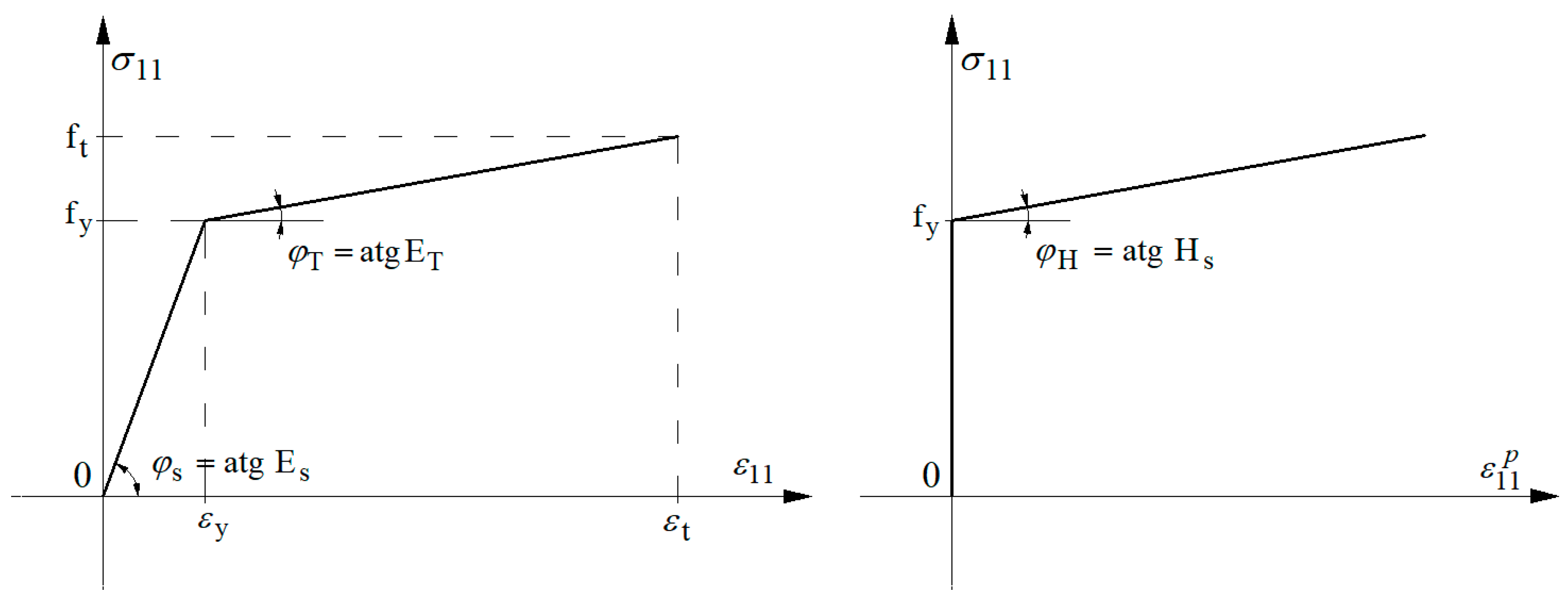
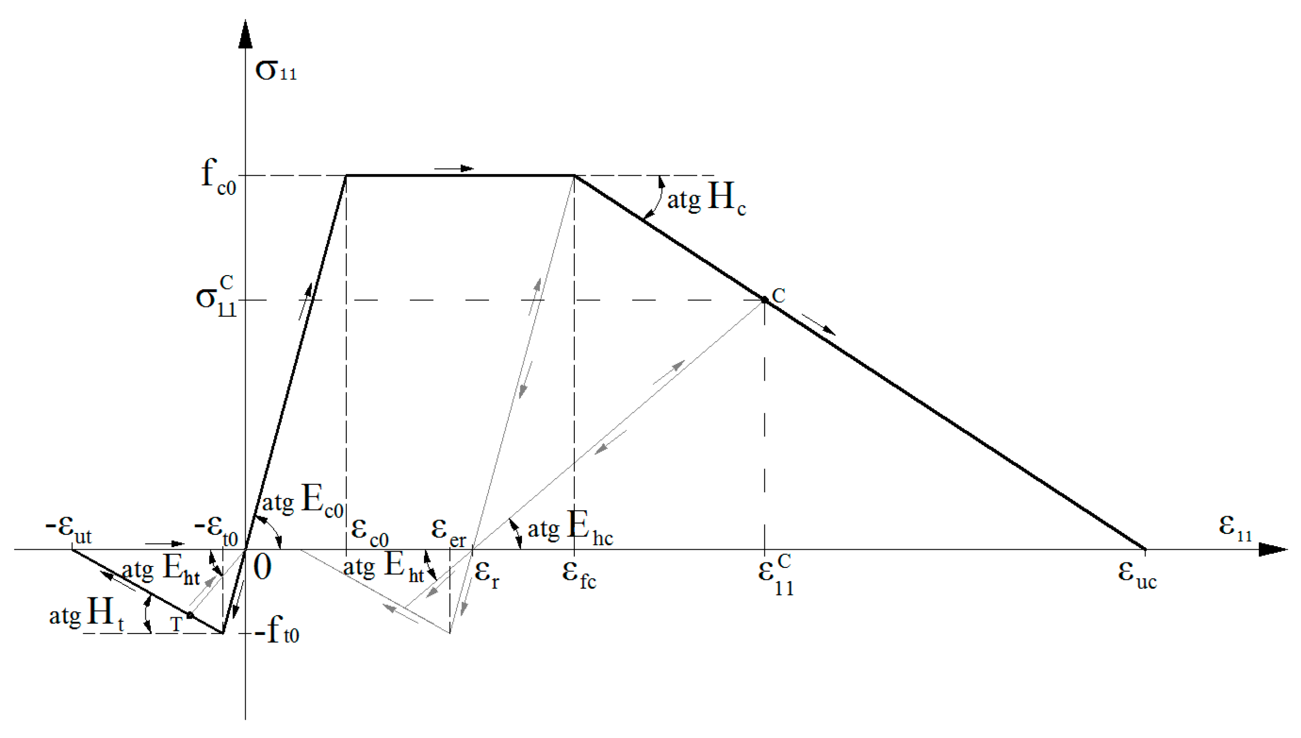
To obtain a solution, the modeling range of the inelastic material properties, the deformation processes of the bar structural elements, and the numerical solutions must be considered. The properties of the structural material were modeled by assuming a reduced plane in a compressive/tensile stress state with shear. An elastic-plastic material model with hardening for the reinforcing steel was used. The elastic-plastic material model was developed by considering the stress softening and degradation of the deformation modulus for the concrete. Analysis of the structural element includes a description of the behavior of an eccentrically compressed reinforced concrete element, which was modeled as a bar system under static loading. The equations for moderately large displacements of the bar include the influence of the longitudinal deformations, changes to the rotation angle of the cross-section (curvature), and isochoric strains. These equations were used as the basis of a theoretical model for the behavior of the structural element.
This technique was implemented into the own computer program to calculate strains, stresses, internal forces, and displacements.
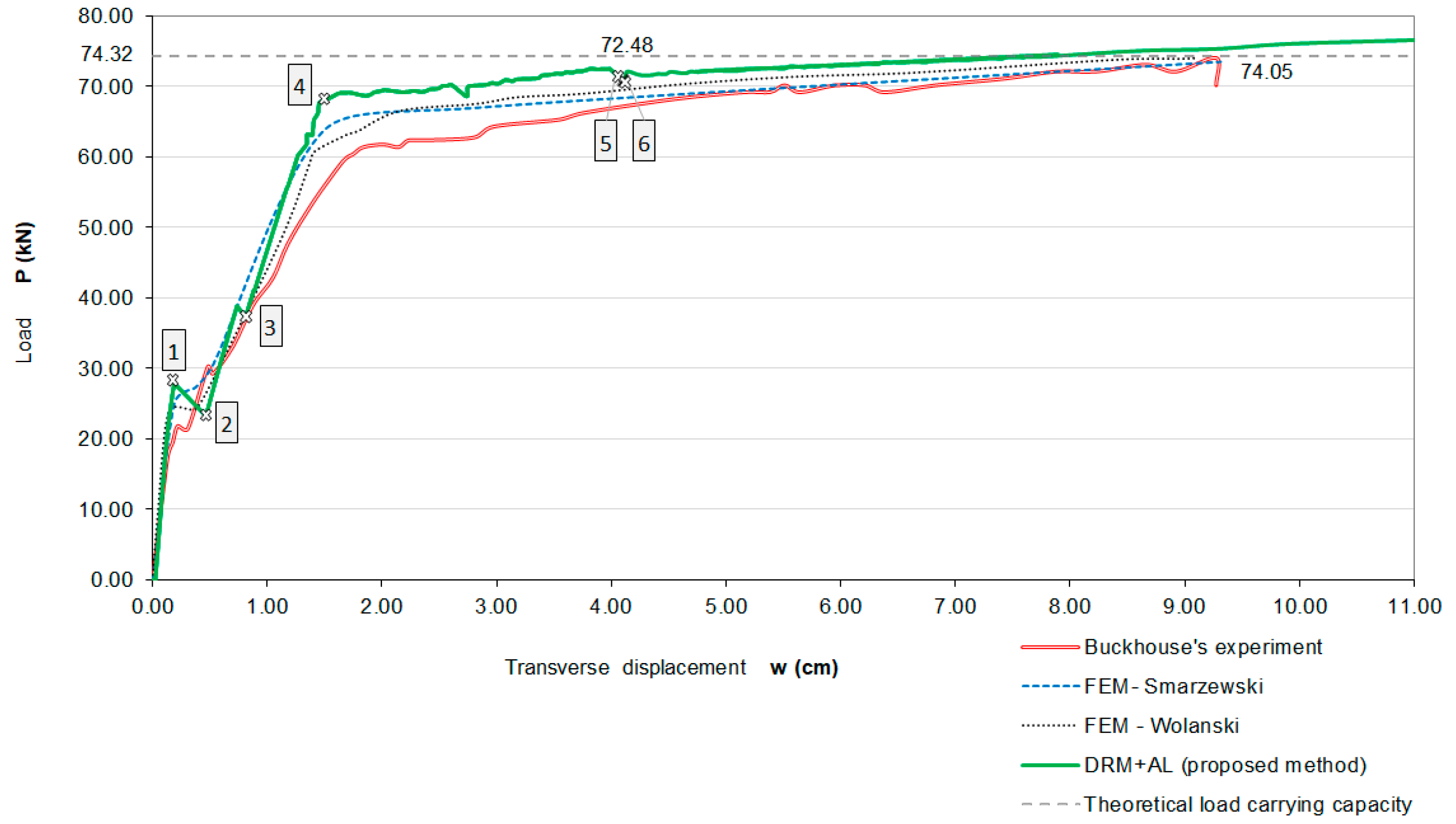
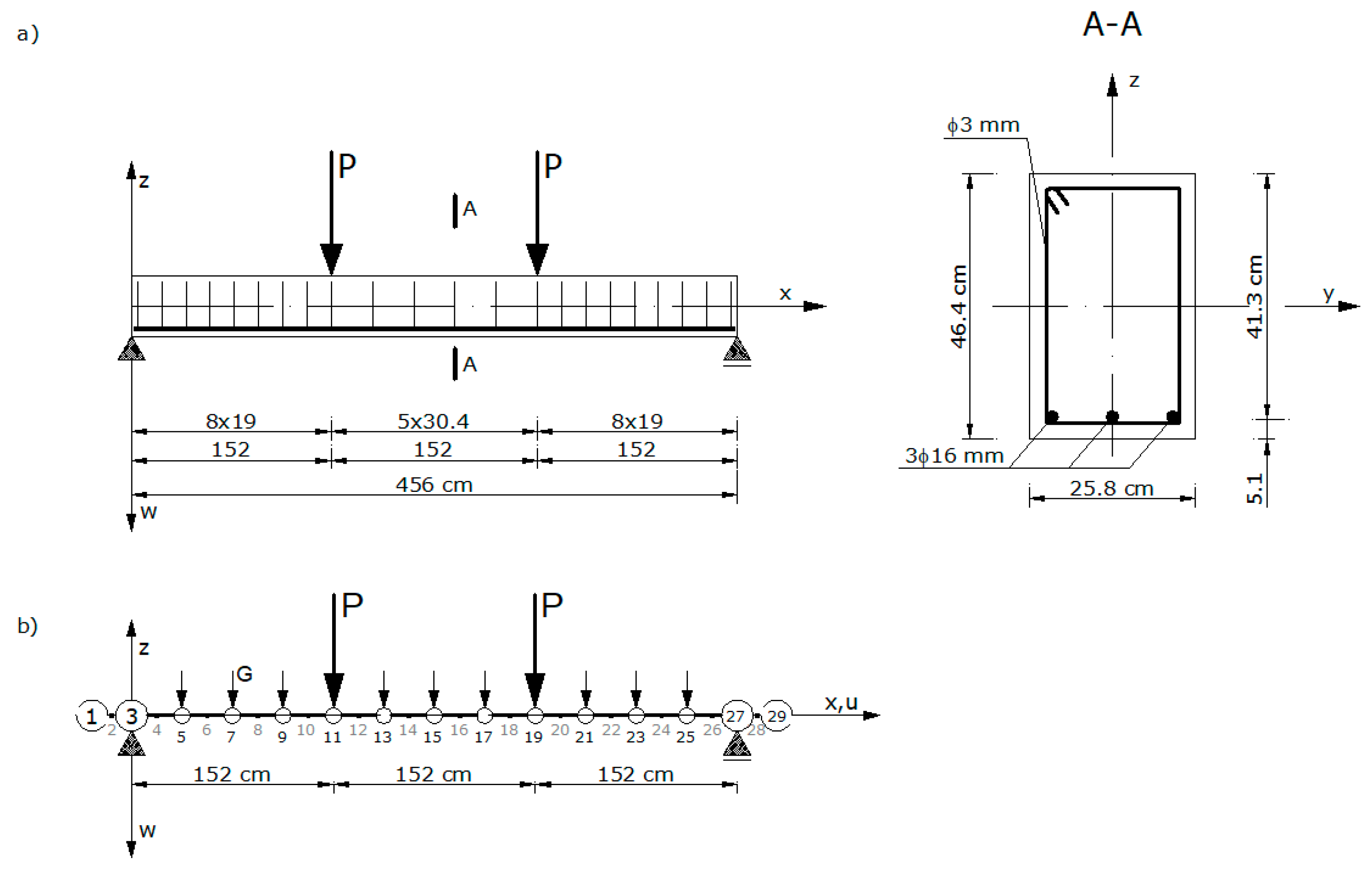
To verify the accuracy of the proposed method, numerical studies of bar structural elements were carried out. The simulations considered a bent reinforced concrete beam that was tested experimentally by Buckhouse [
27,
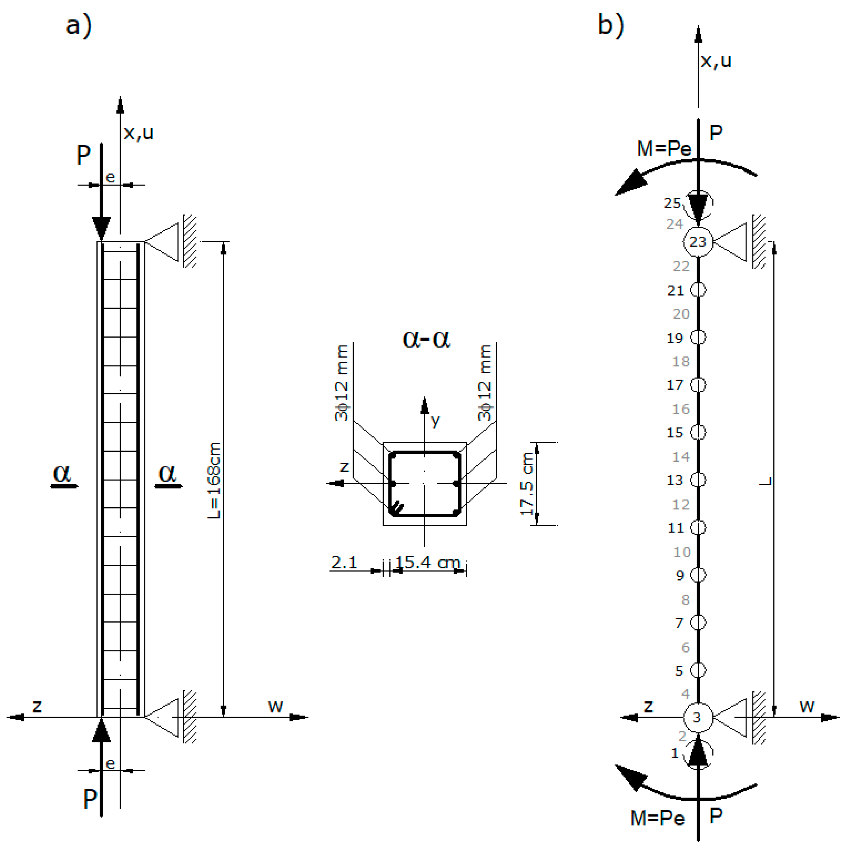
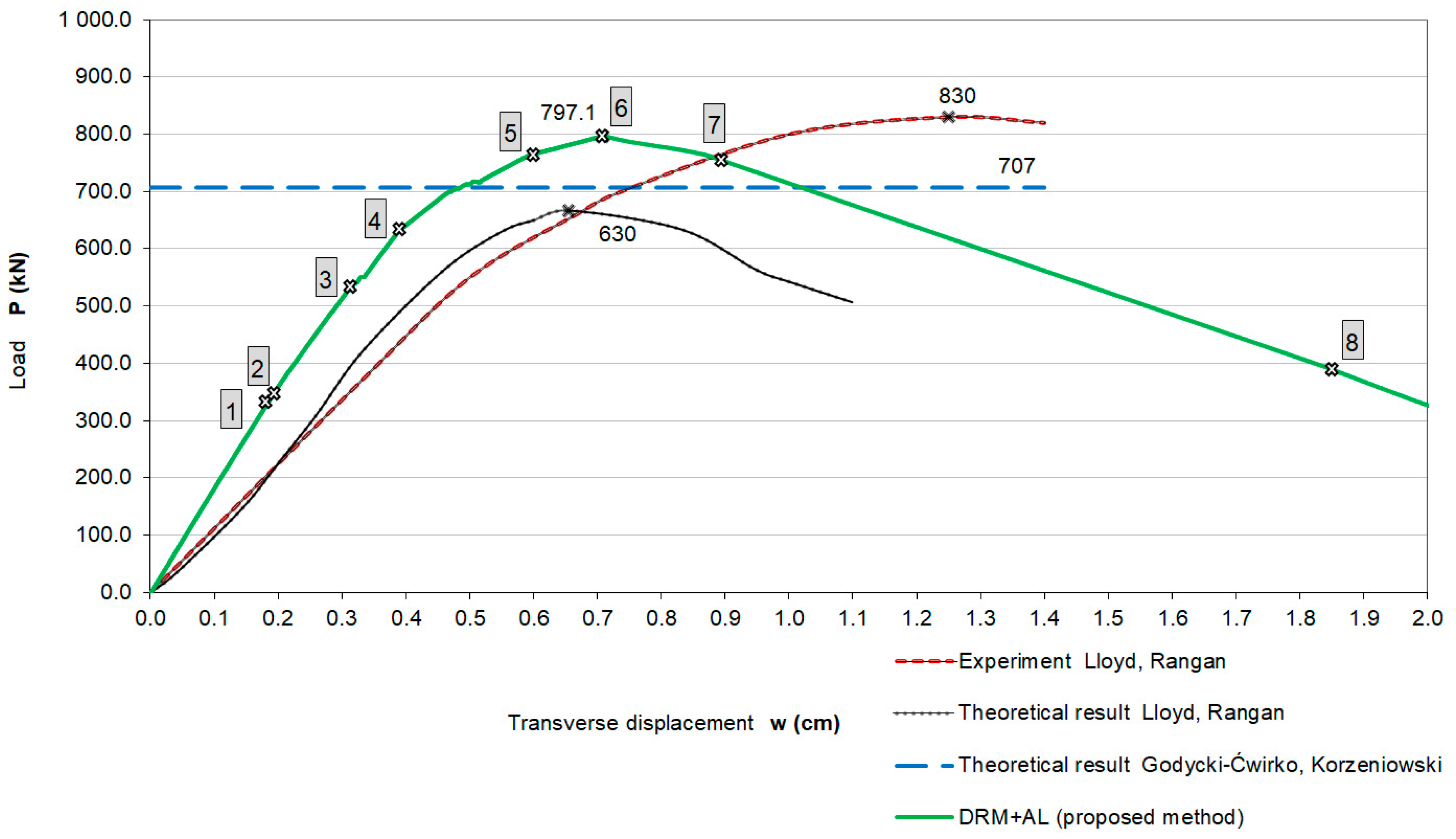
28] and an eccentrically compressed reinforced concrete column that was tested experimentally and analytically by Lloyd and Rangan [
29].
Obtained numerical results were compared with the results of experimental, analytical, and theoretical works from the existing literature.
3. Fundamental Equations
3.1. Equations of Motion
The analysis includes the behavior of bent and eccentrically compressed reinforced concrete elements. The elements are modeled using a system of plane bars and takes into account the initial curvature. The bar system is statically loaded with a short-term longitudinal force, bending moment, uniformly distributed load, and concentrated forces acting on the plane perpendicular to the longitudinal axis of the element.
This reinforced concrete element considers specific geometrical factors including the variable cross-sectional distribution of concrete and reinforcing steel areas, the initial curvature, and the boundary conditions that result from the support and external load.
The equations of dynamic motion for a reinforced concrete bar element that is characterized by the unit mass (
), the unit mass of inertia
, and the unit damping coefficients for the displacements
and rotations
were derived. The problem of the damping coefficient estimation was detailed in the paper [
33].
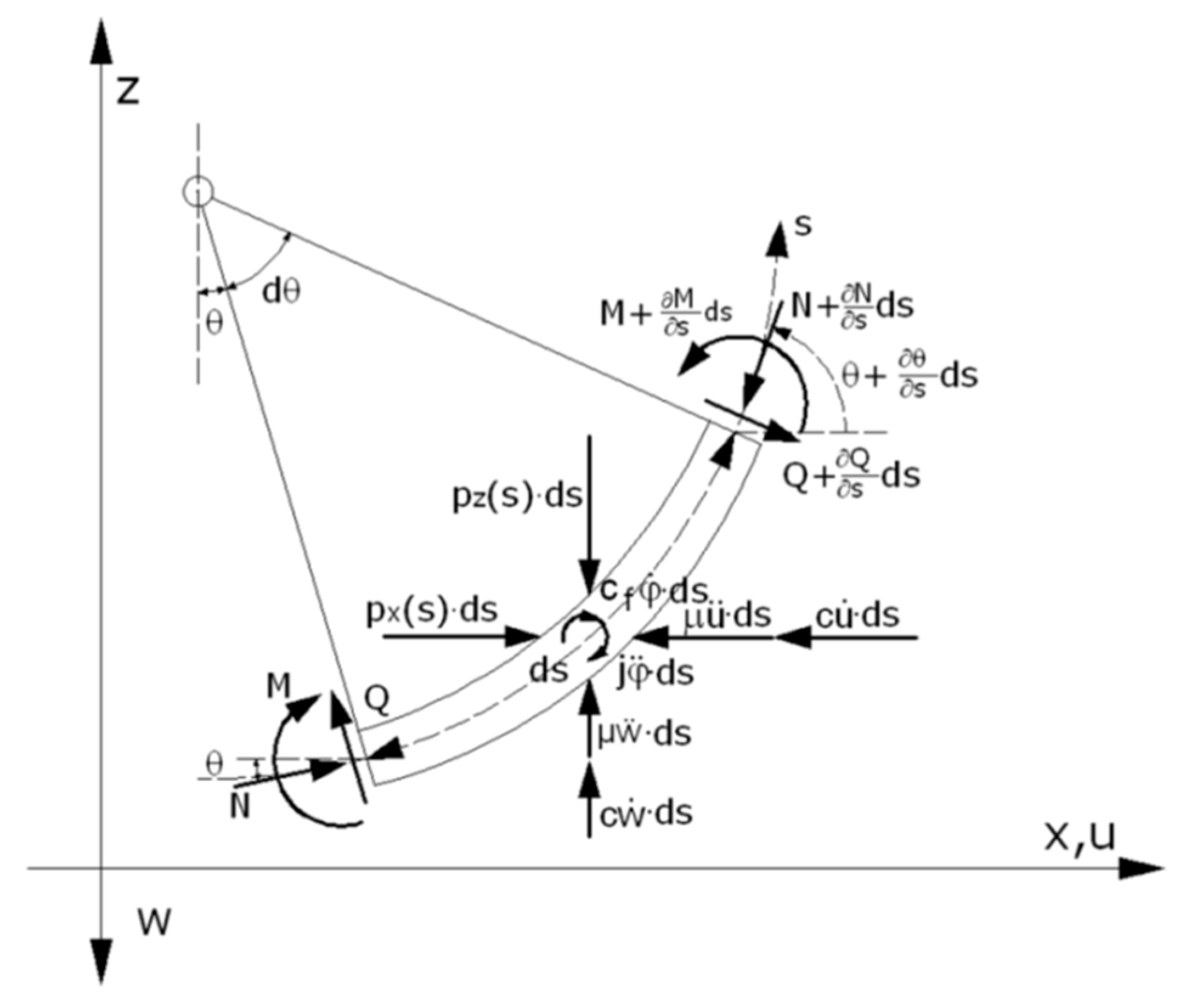
The differential equilibrium equations were defined in the global Cartesian coordinate system
, as shown in
Figure 4, where
is the length of the deformed element, and
is the slope angle. They have the form shown below.
where
is the internal longitudinal force,
is the transversal force,
is the bending moment,
are the external loads, and
are the inertial longitudinal, transverse, and rotational forces.
The linear geometrical relationships that relate to the longitudinal deformation of the central axis
, to the change of the average rotation angle in the cross-section
, and to the average non-dilatational strain angle
are defined below.
where
is the average rotation angle of the cross-section, and
is the rotation angle of the bar’s central axis. In Equation (10), the index
indicates the initial position of the un-deformed bar structure. We determine the value of
according to Equation (10). We assumed that the positive longitudinal force is compressive.
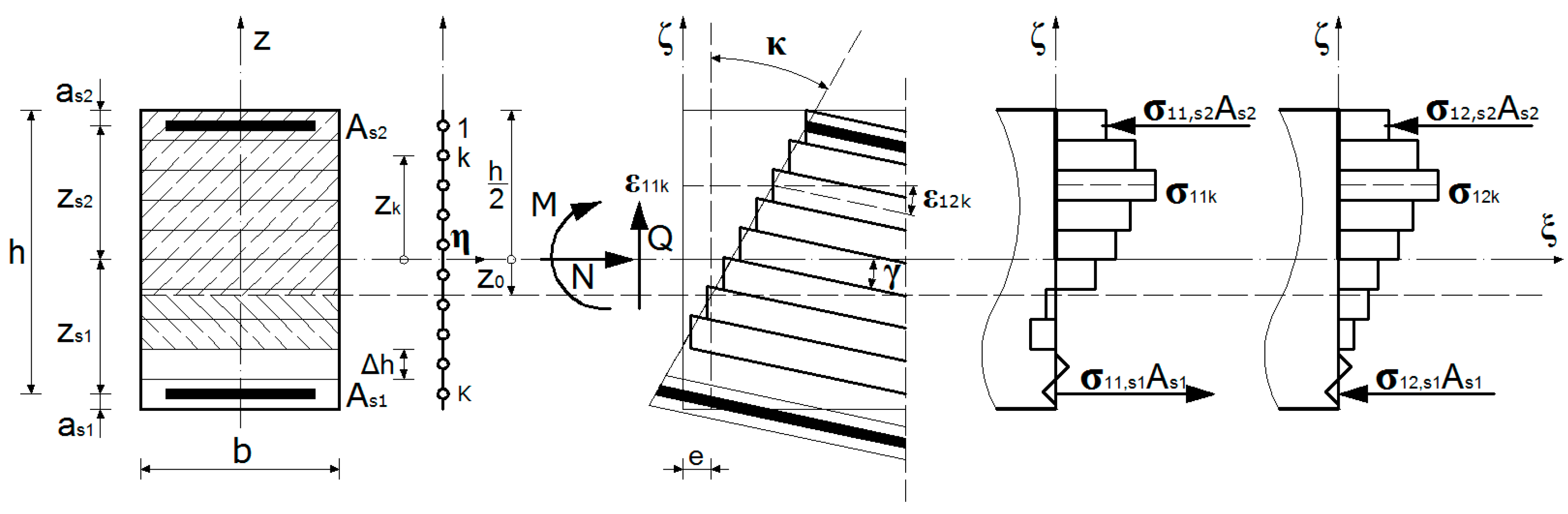
3.2. Equations of Internal Equilibrium in the Cross-Section
The bar’s cross-section was discretized to produce a computational model. The cross-section of the concrete was divided into layers that were
—thick and, within this, the areas of the two steel layers were defined as
and
, which is shown in
Figure 5.
The functioning of the computational cross-section model is conditioned by models of deformation of concrete and steel, as well as by kinematic hypothesis. The basis of this hypothesis is the assumption of plane cross-section that is not perpendicular to the central axis of the deformed element. Kinematic hypothesis determines the state of deformation of all the layers of the cross-section, as well as the principle of active layers in joint action, such as steel layers and concrete layers being able to carry the stresses.
Depending on the ability of concrete for compressive and tensile deformation, the concrete layers carrying the stresses and layers not carrying the stresses, such as cracked layers (in tension) or crushed layers (in compression), were distinguished. Cracked layers after the closing of cracks can again carry the compressive stress, but the crushed layers become permanently passive layers and cannot carry any stresses.
The strain states in the different cross-sectional layers, for a given time step, are defined in Equation (11).
If the longitudinal strain of the central axis (
), the change in the average rotation angle of the cross-section (
), and the average angle of the non-dilatational strain (
) were known, then, after using the material models, the longitudinal force (
), the bending moment (
), and the transverse force (
) can be determined from the equilibrium equations of the cross-section.
where
is the cross-section area of the concrete layer and
is the cross-section area of the tensile/compressive reinforcing steel.
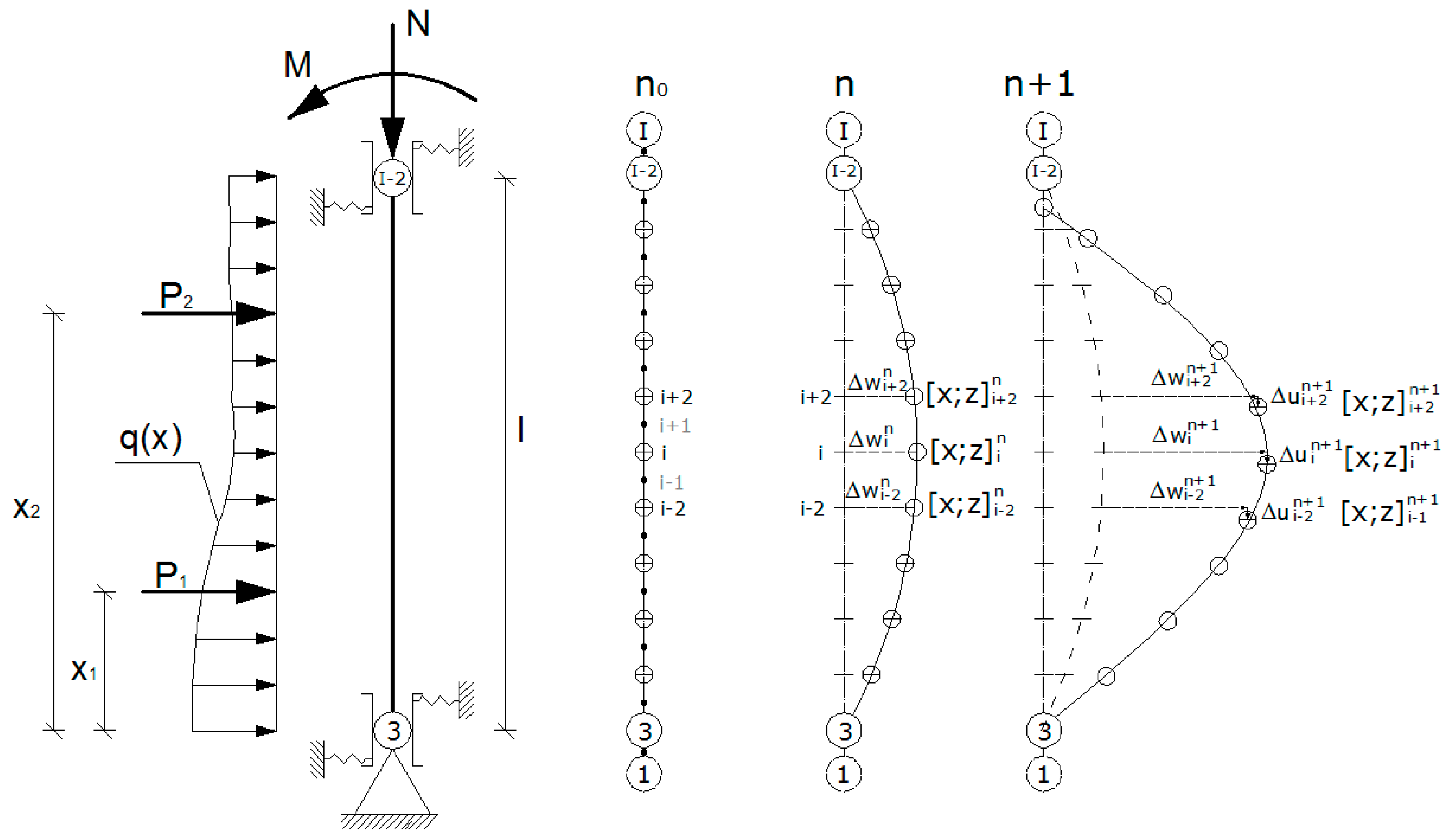
3.3. Differential Discretization of the Bar Element
The equilibrium Equation (9), geometric relationships (10), material models for reinforcing steel (1) and concrete (8), and the cross-sectional model defined by Equations (11) and (12) form the problem within the technical theory of bar structures.
The basic system of equations is presented in differential form on the basis of the proposed discretization of the computational model.
To discretize the model, we divided the central axis of the bar into nodes with coordinates
, for
, which is shown in
Figure 6.
In the proposed model the element was divided into inner and boundary nodes. The internal nodes contain the main nodes (odd), which correspond to the division points, and the intermediate nodes (even), which correspond to the line segments that join the division points.
The main nodes are treated as cross-sections in which the curvatures and the bending moments are accurately calculated. Then, the longitudinal and transverse forces are determined using the average longitudinal strains on the central axis and the angles of the non-dilatational strains determined in adjacent segments.
For the intermediate nodes, the longitudinal strains of the central axis, the angles of the non-dilatational strains, and the longitudinal and transverse forces are accurately calculated. Then, the bending moments are determined using the average curvatures of the adjacent main nodes.
After including differential discretization of the bar element, the equilibrium Equation (9) can be rewritten for the nodes of the spatial division in the form below.
where
and
represent the segments of the internal spatial division,
and
are the longitudinal and transverse forces in segment division
,
is the bending moment on main node
and
are the components of the load in node
. The lumped mass of main node
is below.
where
—average length of the segment division,
is the unitary mass of the reinforced concrete element with cross-section
, and
is the density of the reinforced concrete. The unitary mass inertia moment of the reinforced concrete segment
is characterized by the central (main) moment of the rotary inertia
.
The damping factor for displacements in the main node
determines the relationship.
The damping factor for the rotations of the segment division
is below.
in which
is the unitary damping factor for the displacement of the reinforced concrete element characterized by a frequency and vibration period of
and
is a unitary damping factor for the rotation of the reinforced concrete element that is characterized by a frequency and rotational vibration period of
.
Let
be the critical value of the frequency and vibration period, and the critical value of the frequency and rotational vibration period of the undamped elastic vibrations of the reinforced concrete elements, respectively. Then:
Discretizing the central axis allows for the rewrite of the differential formulation among the geometrical compounds (10) as shown below.
for the main nodes
, and:
for the segments
. In which
is the average of the rotation angles of the cross-section for the segment
.
and
is the average of the rotation angles of the central axis for the segment
.
The rotation angles
in Equation (21) for the segment
, taking into account (10)
3, can be calculated using Equation (22).
4. Solution of the System of Equilibrium Equations
The system of Equation (13) describes the dynamic inelastic behavior of a reinforced concrete element. It was solved using critical damping for displacements
and rotations
, which describe the static problem in the limiting transition. This method is called the dynamic relaxation method. To increase the effectiveness of this technique for the post-critical analysis, the method of solution path tracking for multiple variables [
25] was applied to the solution of the system of dynamic nonlinear equilibrium equations.
The general idea of this method is to incorporate the additional constraints equation that links the load parameter and the vector of displacement increments with the arc length increment on the solution path to the equations of motion (24).
4.1. Numerical Solution of Equations of Motion
The system of Equations (12) was solved using a numerical method and a discretization with respect to time. For this purpose, the direct differential method with respect to time was applied.
In this method, acceleration
and displacement velocity
were approximated in the system of Equations (13) at time instants
,
, and
, using Equation (23).
Using these approximations, the system of Equation (13) becomes the following.
where
is a vector of searched displacement increments,
and is increment of the load parameter in the current time step.
The vector of components of the displacement increments for the total load has the following form.
where
is a selection operator and
is the node number.
The vector of components of the displacement increments for the load parameter
from the previous time step has a form.
where
is a coefficient for linear displacements,
is a coefficient for internal forces,
is a coefficient for rotations, and
is a coefficient for bending moments.
The initial conditions for time step
have the following form.
The iterative procedure terminates when the solutions of displacements in subsequent time instants have converged, according to the condition below.
The time step
is determined so that the numerical integration is stable and has the following form.
where
is the critical time step for the longitudinal elastic vibration problem,
is the critical time step for the elastic bending problem,
is the critical time step for the elastic isochoric wave propagation,
is a safety factor for the time step,
is the bending rigidity of the reinforced concrete cross-section in the elastic range,
is the moment of inertia of the un-cracked (elastic) reinforced concrete cross-section, and
is the largest total reinforcement ratio for the entire reinforced concrete element.
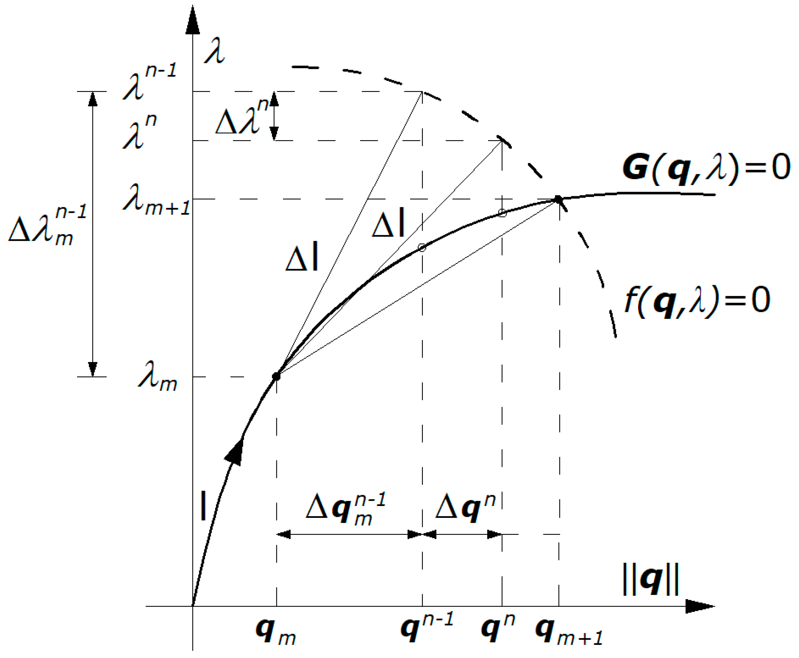
4.2. Conceptual Algorithm for Solving the Extended System of Equations
The extended system of equations was formed by combining the system of equations of motion (24) with the constraints equation
, and can be expressed as Equation (30).
This system for any time instant can be iteratively solved and can be used to determine the searched displacement vector and the load parameter for the nonlinear equilibrium path containing the local limit points.
The constraints equation has the following form [
25].
where
is the increment (parameter) of the arc length on the solution path,
is a vector of the searched displacements,
is the increment of the current load parameter
,
is the increment of the current vector of unknown displacements
in relation to the last convergent values of the load parameter
and displacement vector
, which were obtained with the assumed accuracy in the previous load step
.
Directly solving the constraints Equation (31) allows for us to determine the load parameter
. The solution requires checking the differentiator
sing and was determined according to the following two equations.
and
Then, the solution is selected as the smallest “distance” away from the solution that was obtained in a previous load step
. The smallest “distance” responds to the smallest angle (or the largest cosine of the angle) between the solutions in actual load step
and the previous one
:
Analyzing the conditions of the solution to the constraints Equation (31), indicates that this criterion can be described by the following equation.
This extended system can be solved using a two-stage procedure described below.
On the basis of carried out numerical experiments, it was determined that the accuracy should satisfy .
Figure 7 shows the iterative scheme for solving the extended system of Equations (30).
6. Conclusions
The paper presents a behavior analysis method for the bending and compression of reinforced concrete elements that are subjected to short-term static loads. The structural system analysis technique was developed using assumptions from the finite difference method. The central axis of the structural element was discretized, and the equilibrium equations and geometrical relationships in differential form were written. A joint-action rule was determined for the active concrete and steel layers of the discretized cross-sectional model.
A dynamic process that can describe the static problem by introducing critical damping, was analyzed. When this procedure is used to solve a system of nonlinear equilibrium equations it is referred to as the DRM. Using the DRM, the equations of motion can be recursively solved in subsequent pseudo-time instants for each node of the spatial division. There was no need to solve the system of algebraic equilibrium equations. The DRM was improved by introducing an additional constraint equation to the system of equilibrium equations based on the assumptions of the arc length method. This method is called the DRM + AL, and can be used to solve the nonlinear equilibrium equations in the post-critical range.
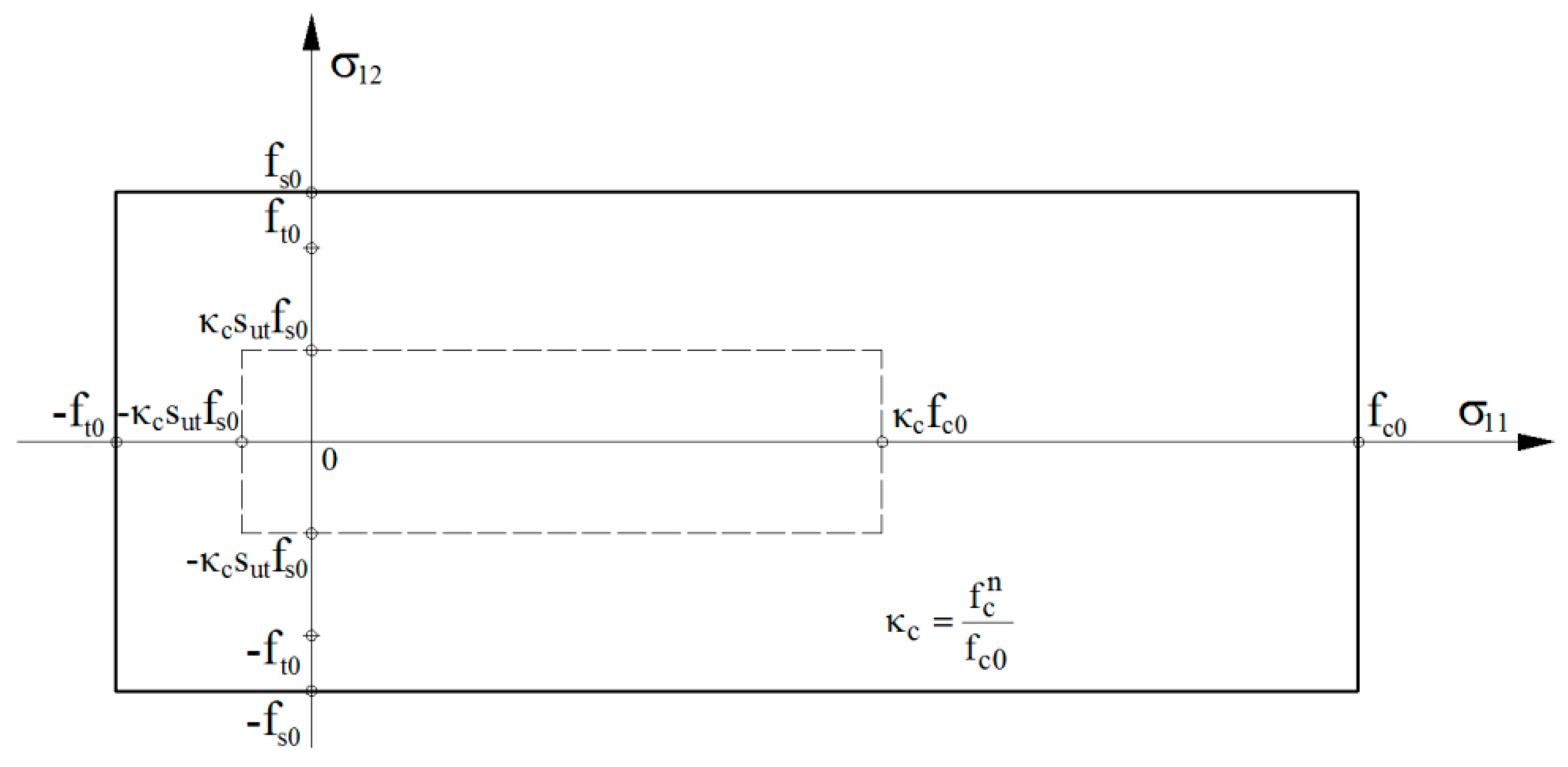
When modeling the behavior of structural materials, the reduced plane compressive/tensile states with shear stress was considered. Equations that were derived from the theory of moderately large displacements in a bar system form the basis of structural behavior description by assuming infinitesimal deformations. This assumption is appropriate when describing strain and stress states in the concrete and steel layers of commonly used reinforced concrete elements.
To verify the effectiveness of the developed method, numerical tests on a reinforced concrete beam and eccentrically loaded column, were carried out.
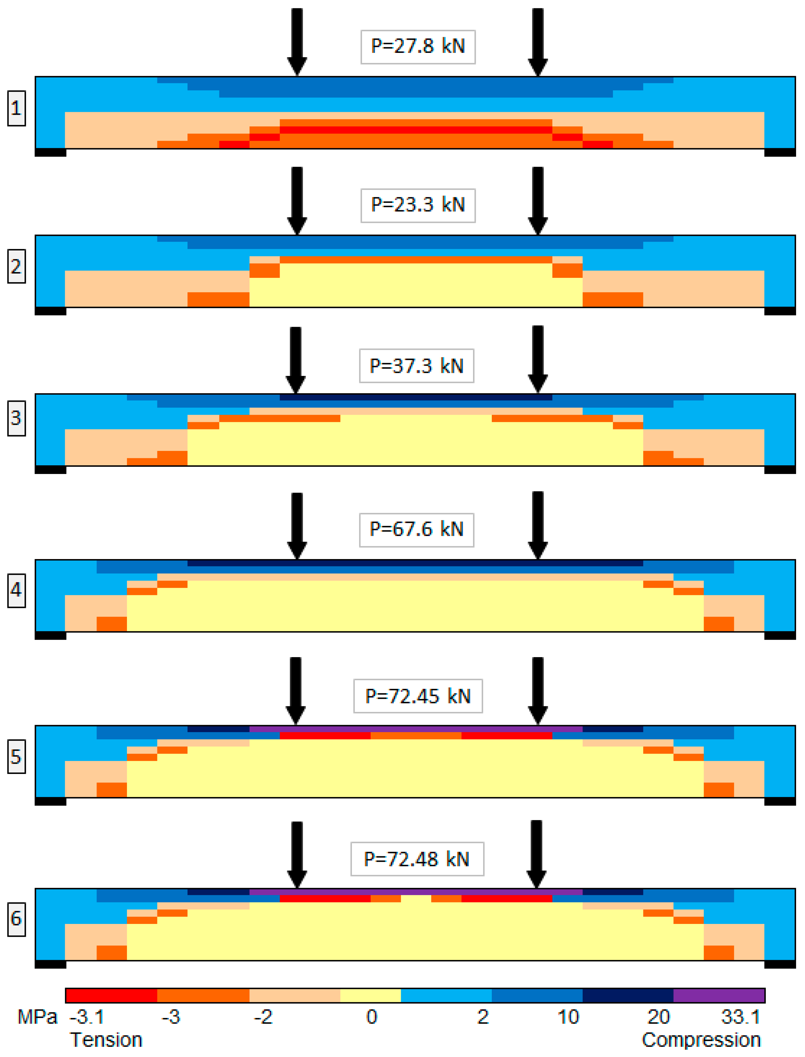
The reinforced concrete beam was analyzed in terms of its load-carrying capacity and displacement. The influences of isochoric deformations, and the shear and tensile strengths of concrete were considered. Numerical results described displacement changes with regard to the structural member in subsequent phases.
The comparative analysis, which was performed for reinforced concrete structural elements indicates that obtained numerical results agree with the experimental results. In case of a beam, numerically determined load carrying capacity is 3% lower than those that were determined in experiment. The load-carrying capacity of the column is 4% lower than the experimentally determined load, and the displacement corresponding to the load-carrying capacity was 50% lower. The results obtained using the dynamic relaxation method with the arc-length method are the most similar to the experimental results, when compared with the other analysis methods. For both of the structural elements, the proposed method enabled extensive analysis of the post critical effort.
The conclusions are summarized as follows.
Comparative analysis of the results obtained for the bent and eccentrically compressed reinforced concrete elements indicate that the proposed method accurately estimated the load-carrying capacity.
The considerations carried out and the obtained results of numerical analysis confirm the high efficiency of the developed computational method.
The proposed method of dynamic relaxation taking into account the constraints equation for the non-linear equilibrium path enables the simulation of inelastic behavior of reinforced concrete elements in the range of continual formation for the failure mechanism.
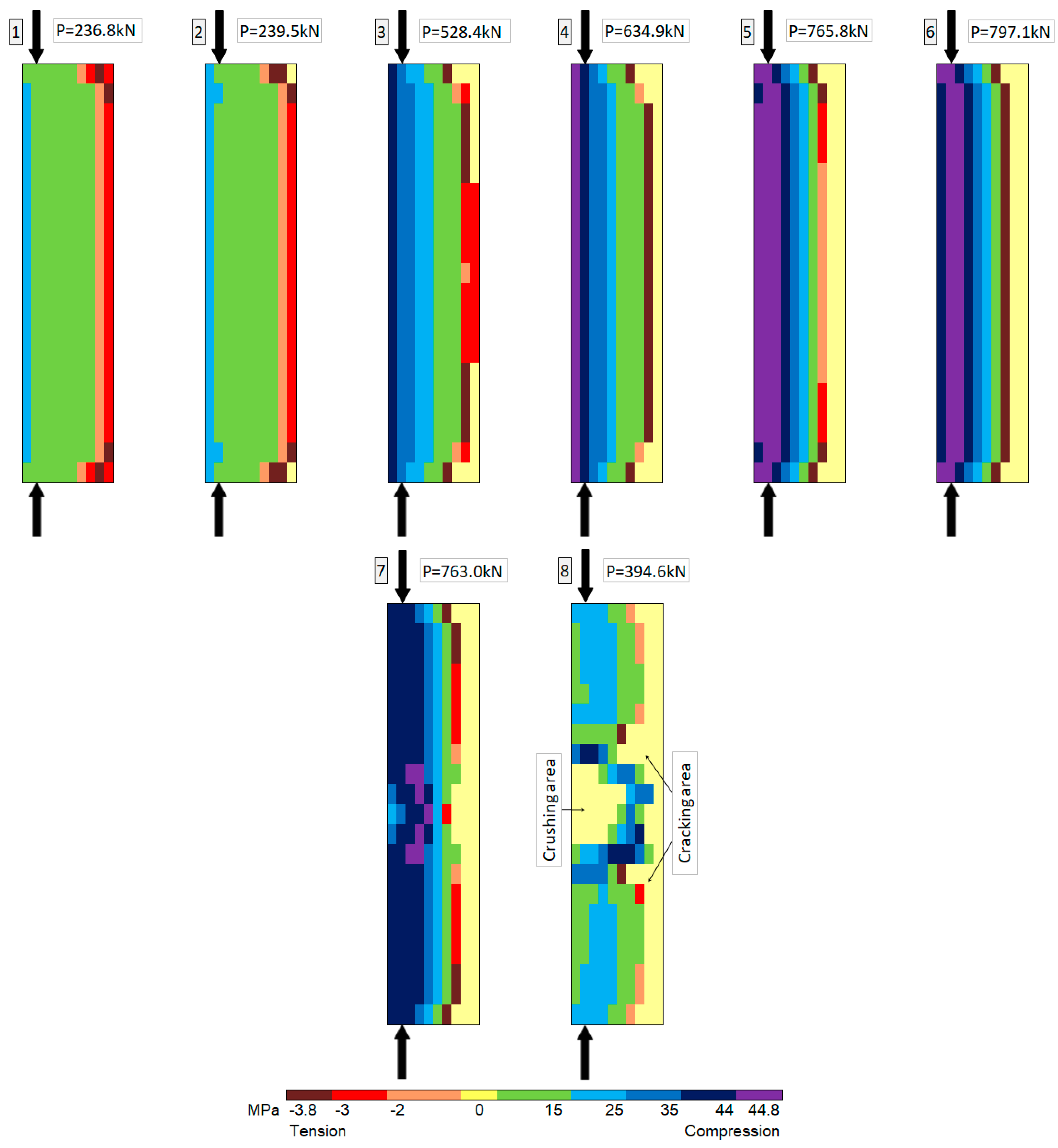
The numerical method is useful for tracking the global softening process of the structural element, in such that the range that cannot always be observed in the experiment because of the measurement limitations.
A greater stiffness was observed in the computational model when compared with previously published experiments. This effect is a consequence of the concrete modeling method.
In the inelastic range, there was a reduction in the displacement associated with the critical damping factor, which was determined using the longitudinal and flexural stiffness of the column in the elastic range.
The computational method could be improved by further modifying the concrete model and by introducing a damping factor dependent on the inelastic state of the element. This would result in more precise estimates of the displacement.
The proposed computational method is suitable for a post-critical analysis of the bending and eccentric compression of inelastic reinforced concrete elements.
The proposed method is very useful for predicting the development of structural elements failure and for allowing a better analysis of the construction systems’ safety.
