1. Introduction
In recent years there has been a great development of energy harvesting techniques based on piezoelectric devices. Piezoelectric cantilever harvesters have been successfully used for transforming ambient vibration energy into electrical energy for feeding sensors, biomedical equipment, and small electronic devices [
1,
2,
3]. The trimming of the harvester to the vibration source is essential to improve the vibration-to-electric energy conversion. In the presence of harmonic vibrations, optimum trimming is achieved when the natural frequency of the harvester is set equal to the vibration frequency [
4,
5].
When the difference between the frequency of ambient vibrations and the resonance frequency of the harvester is not very large (some tens of Hz) the problem of trimming is solved by adding a tip mass [
5,
6,
7], which increases the excitation of the harvester because the inertia force due to the lumped mass adds to the inertia forces due to the distributed harvester mass. This phenomenon has a beneficial effect on the generated voltage, but it increases the stress inside the harvester, which may be damaged.
When the frequency of ambient vibrations is very low (e.g., in energy harvesting from human motion) the tip mass able to trim the harvester would be impractically large. Therefore, several frequency-up strategies have been proposed: they are based on specific devices like a flexible stopper [
8], a non-linear plectrum [
9], or a pendulum magnetically coupled with the harvester [
10].
The problem of harvester trimming is complex when ambient vibrations are characterized by variable frequency, by multiple harmonic components, and by the broadband spectrum as well.
Several technical solutions have been developed to cope with these working conditions. Some researchers have proposed dynamically tunable harvesters, in which tuning can be achieved both by means of the interface circuit [
11,
12] and by mini-actuators that modify the mechanical system [
13]. Other researchers have developed wideband harvesters. One approach consists in exploiting several modes of vibration of the cantilever harvester (making use of segmented electrodes) [
14] or of more complex structures, like L-shaped harvesters [
15]. Another approach consists in making use of non-linear components like bi-stable cantilevers or ropes [
16,
17,
18]. The possibility of widening the band of the cantilever harvester by increasing the number of degrees of freedom (DOFs) has been analyzed in some research. In particular, in [
19,
20] two DOFs harvesters have been developed connecting cantilever harvesters with tip masses and the use of arrays of cantilever harvesters is reported in [
5,
21,
22].
The problems of trimming and increasing the bandwidth of a piezoelectric harvester by increasing the number of DOFs can be analyzed with the theory of the Dynamic Vibration Absorber (DVA) [
23]. Since the beginning of 20th century, DVAs have been successfully used for controlling vibrations of many mechanical systems including crankshafts, ships, engines, and machine tools [
24]. In the field of acoustics, the DVA is named the Helmholtz resonator [
25] and it has been used in mufflers [
26] and cavities [
27].
Some studies dealing with the application of DVAs in the field of energy harvesting have been already carried out. For example [
28] proposed to attach lead zirconate/lead titanate (PZT) patches (which harvest energy from vibrations) to an auxiliary structure that acts as a DVA for the main vibrating structure. Several researchers have studied dynamic magnifiers, which are spring-mass systems placed between the harvester and the moving base [
29]. In [
30] the dynamic magnifier was added to a piezoelectric stack harvester and the natural frequency of the dynamic magnifier was set equal to the one of the harvester. Numerical results showed the appearance of two resonance peaks, a large increment in the generated power and a significant widening of the bandwidth of the harvester. In [
31] the concept of the dynamic magnifier was applied to cantilever harvesters. In [
32] a cantilever harvester with tip mass was mounted on a supporting beam for lowering the first natural frequency of the integrated system.
These concepts were further extended in [
33], where all the modes of a cantilever harvester were trimmed to those of a continuous (beam-type) auxiliary structure. Experimental results showed a doubling of resonance peaks in a wide frequency band.
A double-mode harvester was developed in [
34]. In this case the harvester does not behave like a DVA, but a DVA composed of a mass and two helicoidal springs is used for trimming the harvester and for making possible the exploitation of two modes of vibration. A distributed-parameter model and an experiment showed the potentialities of this harvester, but helicoidal springs are not suited to integration with a harvester. A cantilever DVA, in which the spring is a small cantilever beam, is more suited to this purpose.
This research focuses on piezoelectric harvesters having a multi-layer structure with one or more active layers surrounded by layers of structural, conductive, and insulating materials. In these harvesters the structural layer (steel or plastic material) can be extended and shaped to create a cantilever DVA, which is named Integrated Trimming Device (ITD). In a simple ITD the structural layer is extended to create a narrow appendix with a final widening: the narrow appendix behaves as a cantilever beam, whereas the final widening behaves as a tip mass. Many alternative designs are possible in order to shape the extension of the structural layer in such a way that a part basically behaves as a beam and another part basically behaves as a mass.
In order to assess the validity of this concept, analytical calculations and experimental tests were carried out on prototypes made with a simple technology. Results in the frequency domain show that the prototypes are able to transform the original resonance peak of the harvester into a pair of new peaks, like in [
30]. The former peak has lower frequency than the original peak and is used for trimming the harvester to the main source of vibrations. The latter peak makes it possible to collect a significant amount of energy at high frequency as well. This possibility is useful in the presence of periodic vibrations characterized by several harmonic components.
In order to extend the analysis to more complex and realistic ITDs, a multi-physics finite element (FE) model was developed in COMSOL and validated by means of experimental results.
New harvesters equipped with ITDs were designed and modeled in COMSOL extending and shaping the structural layer of a standard harvester. The potentialities of the harvesters equipped with IDTs were investigated by means of numerical simulations. Numerical results are presented in terms of the frequency response functions (FRFs) of generated voltage, generated power, stress, and strain distributions inside the piezoelectric material.
2. Preliminary Design of Prototypes
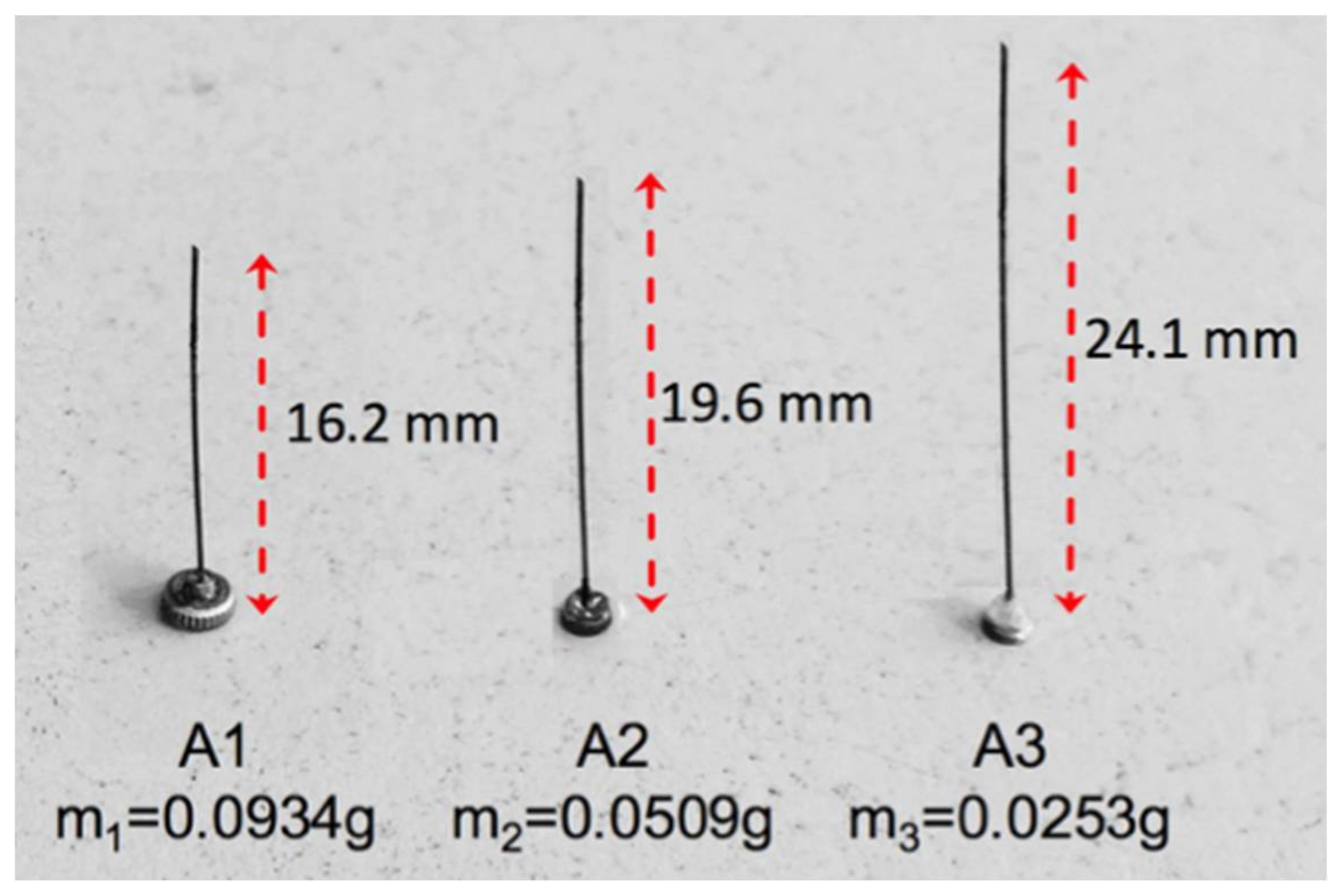
Before developing and modeling the harvesters with ITDs, the validity of the basic concept, i.e., the addition of a cantilever DVA to a piezoelectric harvester, was assessed by means of prototypes built with a simple technology. The starting point was a Piezo Protection Advantage PPA 1001 harvester built by MIDE (Medford, MA, USA). It is a general-purpose unimorph harvester having a rectangular shape (length 41.1 mm, width 20.8 mm), with a PZT 5H piezoelectric layer and a stainless-steel structure.
Figure 1 shows the cantilever DVAs used in the prototypes. The cantilever beams were made using harmonic steel wire (radius
r = 0.15 mm, density
= 7850 kg/m
3); this solution allowed to obtain a structure with low damping. The mass elements were small brass discs, whose masses were measured by means of a balance having a resolution of 0.1 mg.
The cantilever DVAs were connected to the free end of the harvester with a removable connection using wax for the accelerometers. In some tests the cantilever DVA was joined to the harvester using epoxy adhesive. No difference was found between the results obtained with the two joining techniques.
A lumped-element approach was adopted for trimming the natural frequency (
) of the cantilever DVA (having stiffness
and equivalent mass
) to first natural frequency of the PPA 1001 harvester:
Stiffness
depends on cantilever length
, Young modulus
and moment of inertia
of the wire cross-section:
Equivalent mass takes into account the lumped tip mass
and a fraction of the mass of the wire (having density
), making use of the Rayleigh method [
23]:
Equations (1)–(3) show that it is possible to trim a cantilever DVA with assigned tip mass
and wire radius
by varying the length (
) of the cantilever beam. The theory of DVA [
23] shows that an increment in the tip mass (
) widens the frequency interval between the resonance peaks that substitute for the original resonance peak. Therefore, three different cantilever DVA trimmed to the same frequency (
) but with different tip masses were developed.
3. Analytical Model of Prototypes
The prototypes are equipped with cantilever DVAs, which are beams with tip masses and can be modeled with a lumped element approach. Therefore, it is possible to develop an analytical model of the prototype by coupling the distributed parameter model of the harvester [
6,
7] with the lumped element model of the cantilever DVA.
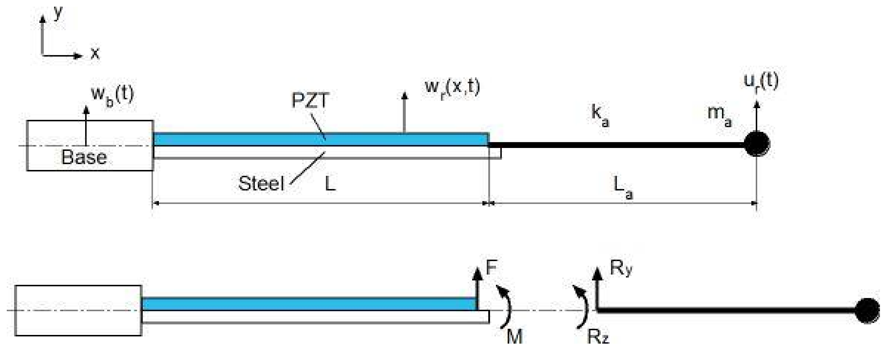
Figure 2 shows a scheme of the model.
is the displacement of the base of the harvester in the transverse direction (), base rotation is neglected since the testing equipment was designed in order to generate only base displacement. is the displacement of any point along the harvester axis with respect to the base, is the displacement of the mass of the cantilever DVA with respect to the harvester tip ().
The partial differential equation of the harvester (having length
) is:
In Equation (4)
is the equivalent bending stiffness of the composite cross-section,
is the mass per unit length of the harvester and
is the strain-rate damping coefficient [
6], air damping is neglected because usually it has a small effect on harvester performance [
7].
is the piezoelectric coupling term [
6] and
is generated voltage. At the right-hand side of Equation (4) there are the forcing terms. The first term is due to base acceleration, whereas the last terms are caused by the force
and the torque
exerted by the cantilever DVA on the harvester;
is the Dirac delta function. It is worth noticing that the loads due to the cantilever harvester are calculated with the same approach adopted in [
7] to calculate the inertia load caused by a tip mass.
The piezoelectric layer can be considered a current
source in parallel with its internal capacitance
[
6] and it is connected to an electrical load that can be represented by a resistance
. The application of the Kirchoff’s laws to this circuit gives the following differential equation:
The ordinary differential equation of the DVA is:
constant
in Equation (6) is DVA damping.
The inertia force and torque exerted by the cantilever DVA on the harvester are:
According to the proportional damping assumption, the equations of motion can be solved with the modal expansion approach [
7]. Displacement
is represented by a series of eigenfunctions:
In Equation (9) is the i-th mass-normalized eigenfunction (mode of vibration) and is the i-th modal coordinate.
Modal expansion transforms Equation (4) into this set of ordinary differential equations:
In Equation (10)
is the undamped natural frequency of the
i-th mode of vibration and
is modal damping. Coefficient
is the backward modal electromechanical coupling term [
6].
The electrical equation and the DVA equation after expansion in modal coordinates become:
In Equation (11)
is the modal electromechanical coupling term [
6].
The forced response of the harvester with DVA can be calculated by solving the system of ordinary differential Equations (10)–(12) considering a finite number of modes. On the one hand the aim of this analytical model is to give a first prediction of the response of the harvesters with trimming devices, more detailed analyses will be carried out with the FE approach. On the other hand, some preliminary results [
35] showed that the second mode of the harvester has a natural frequency much higher than the first and a very small effect on low frequency dynamics. For these reasons, only the first mode of vibration (
i = 1) is considered in Equations (10)–(12). The FRFs of the prototype can be calculated considering the harmonic base excitation:
and looking for harmonic solutions for the first mode of the harvester, DVA displacement, and voltage:
, and are complex constants. The system composed of Equations (10)–(12) becomes a linear-algebraic system, which can be solved numerically by means of MATLAB (Version R2014a, MathWorks, Natick, MA, USA, 2014).
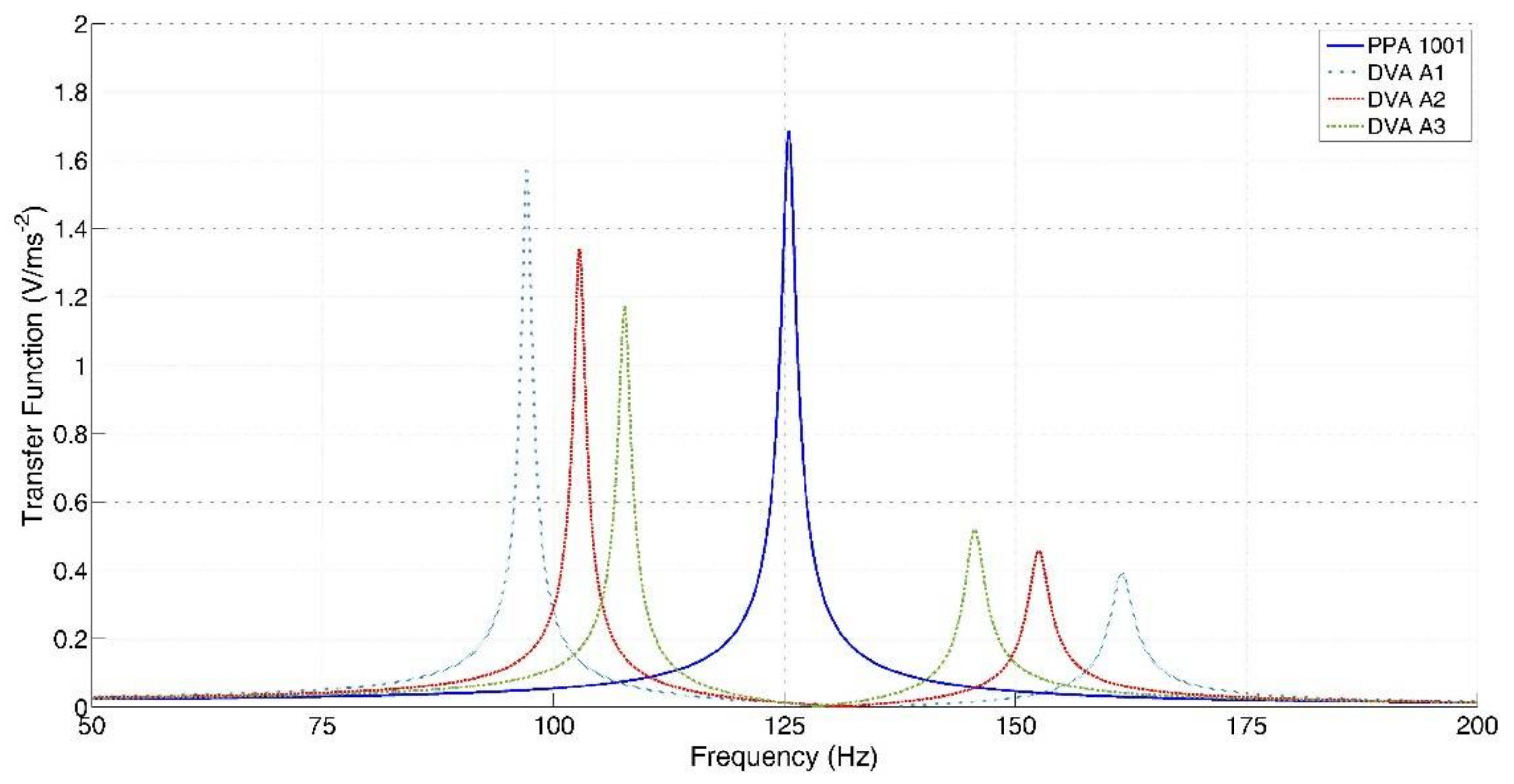
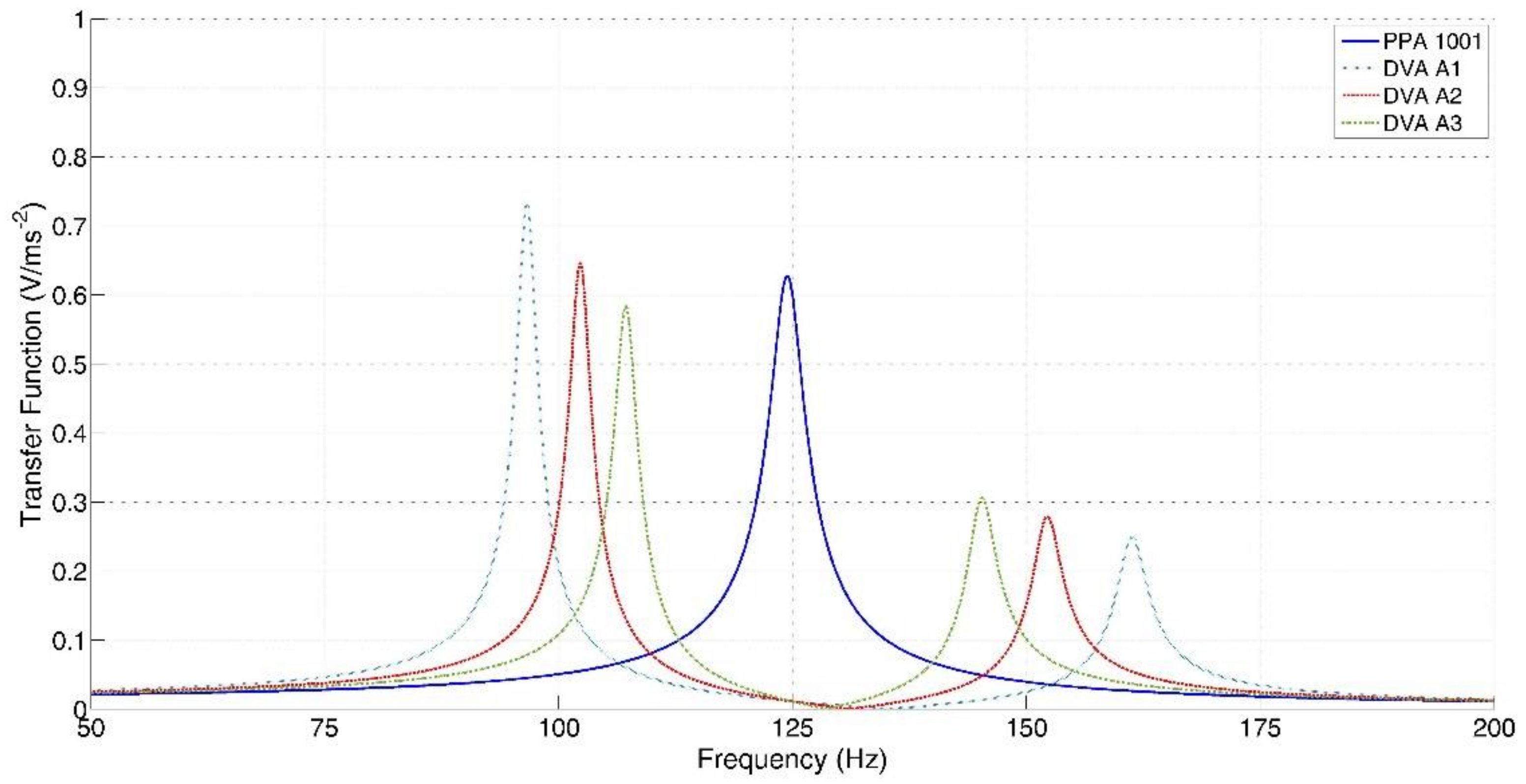
At first the analytical model was used to calculate the FRFs between the open circuit voltage and base acceleration of the three prototypes, because the open circuit voltage is an important figure for the design of the energy conversion system of the harvester [
36]; results are presented in
Figure 3.
When the most massive cantilever DVA (A1) is added to the harvester, the original resonance peak (125 Hz) is substituted by two new resonance peaks at 97.1 and 161.5 Hz respectively, the interval between the two resonances is 64.4 Hz. The first peak is slightly lower than the peak of PPA 1001 alone, whereas the second peak is rather small. If the DVAs with smaller masses are considered (A2 and A3), the frequency interval between the two new peaks decreases, the height of the first peak decreases, whereas the height of the second peak increases.
Table 1 summarizes the resonance frequencies and the corresponding amplitudes in resonance of the three prototypes.
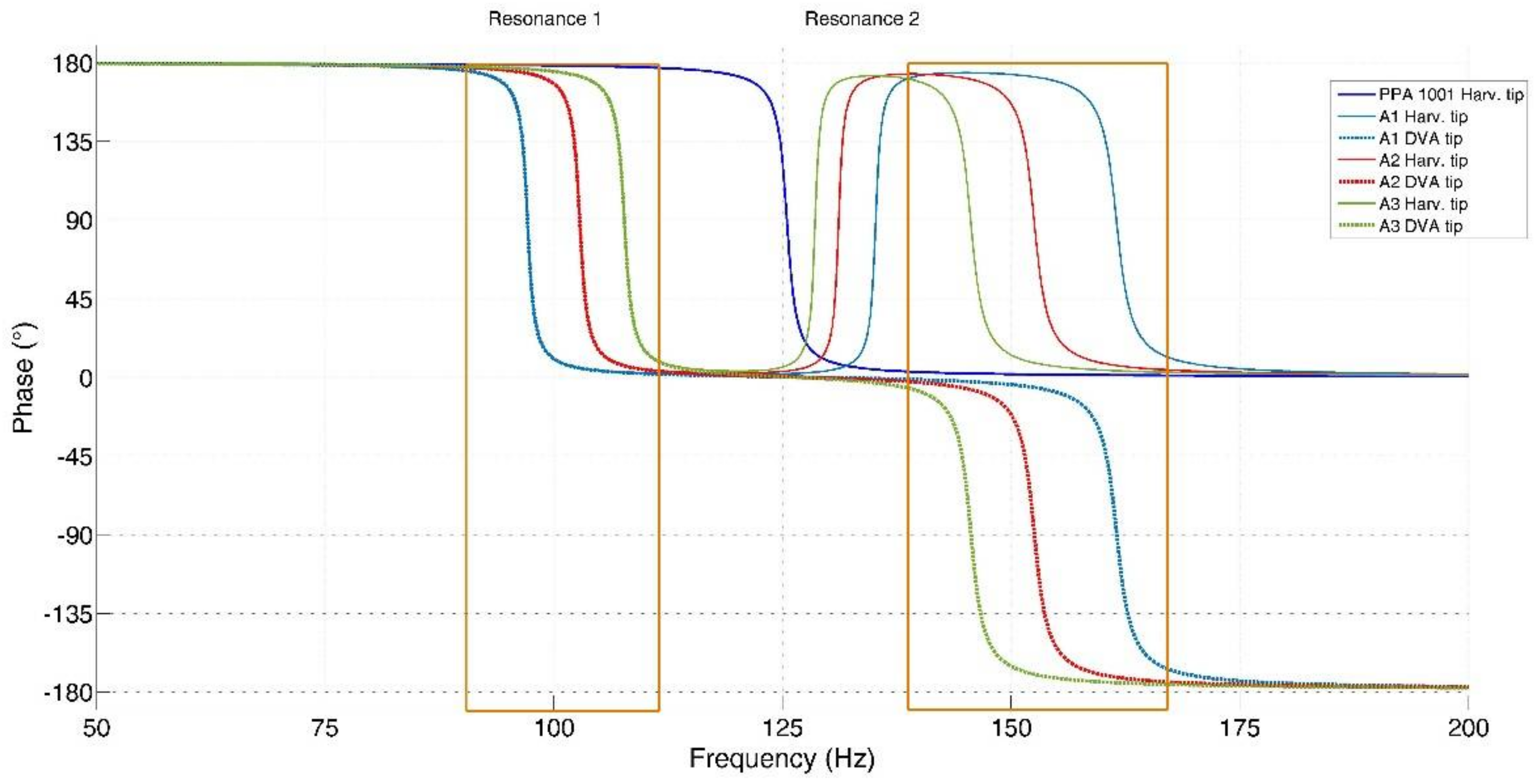
The phases of the modal displacement of the harvester (
) and of the displacement of the DVA (
) with respect to base acceleration give useful information about the functioning of the system.
Figure 4 shows that at the frequency of the first resonance peak of the harvester with DVA, the two displacements essentially have the same phase with respect to base acceleration, therefore the harvester and the DVA move in phase when the first mode of vibration is excited in resonance. At the frequency of the second resonance peak there is a phase shift of about 180° between the modal response of the harvester and the displacement of the DVA, therefore the DVA moves in opposition with respect to the harvester when the second mode of vibration is excited in resonance.
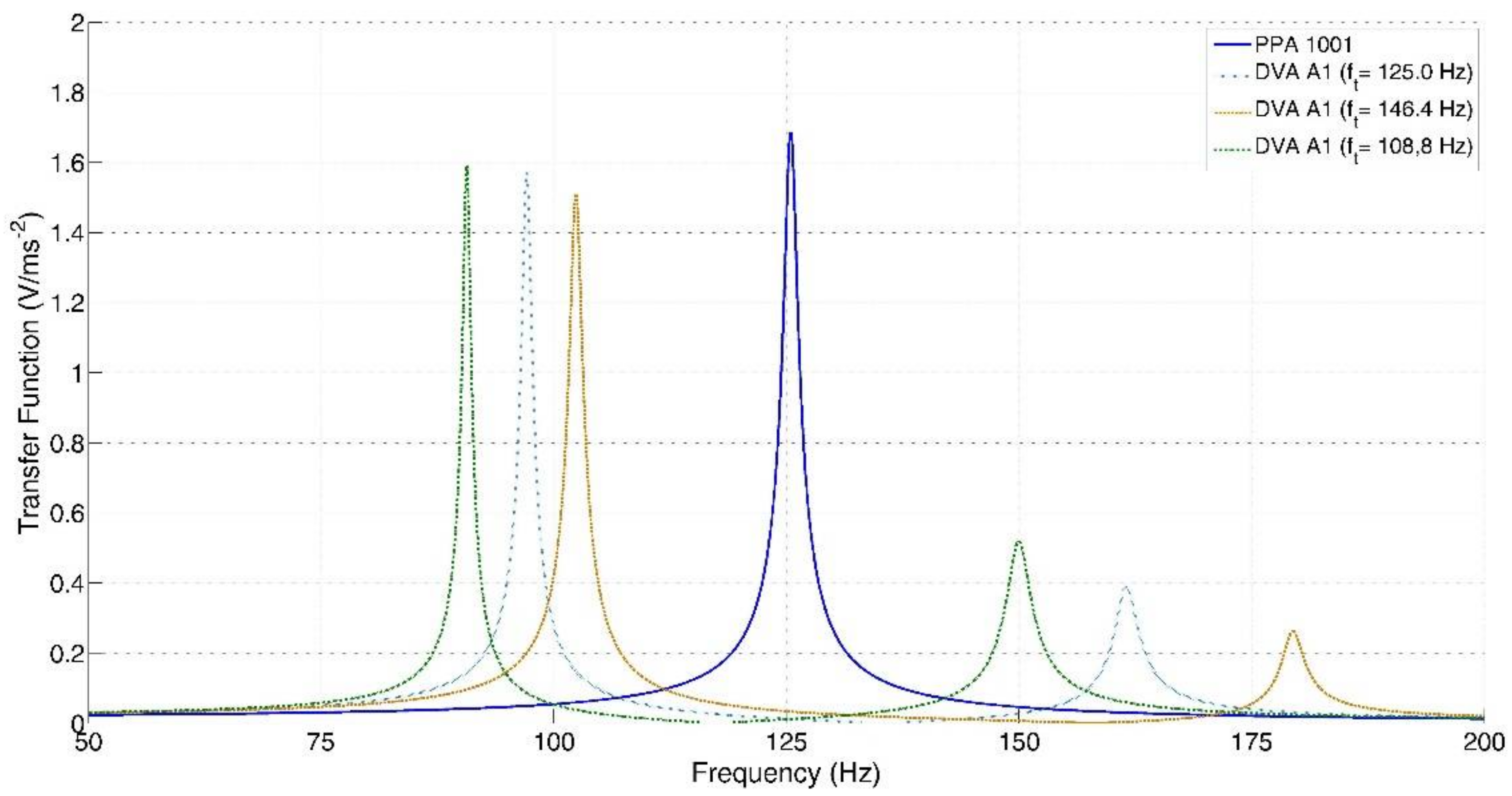
The analytical model makes it possible to analyze the effect of the trimming frequency (
) of the cantilever DVA on the performance of the harvester. Two new versions of A1 are considered: the former with increased length (
mm) and decreased trimming frequency (
Hz), the latter with decreased length (
mm) and increased trimming frequency (
Hz).
Figure 5 shows that, when the trimming frequency decreases, both the peaks move towards lower frequency, and the amplitude of the second peak significantly increases. Whereas, when the trimming frequency increases, both the peaks move towards higher frequencies and the amplitude of the second peak decreases.
When the harvester is connected to a resistive load, the FRF between the generated voltage and base acceleration (
) is related to the generated power. For this reason,
was calculated by means of the analytical model considering the optimal load resistance [
36], which maximizes the generated power at the frequency of the first resonance (
):
Figure 6 shows the predicted FRFs. The load resistance significantly decreases the amplitudes of the resonance peaks. If PPA 1001 alone is considered, the peak frequency slightly decreases (from 125.5 to 124.6 Hz). This effect is in agreement with the results presented in [
6,
37]. Also, when the harvester is coupled with the trimming device the frequencies of the resonance peaks decrease, owing to the resistive load. This effect is more important for the first peak than for the second.
4. Experimental Tests and Results
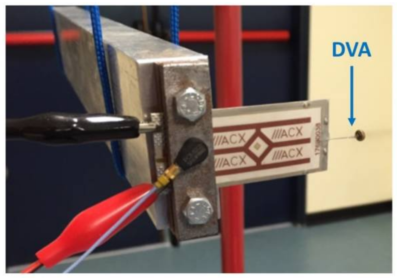
A specific test rig was developed to excite by means of a hammer for modal testing a small harvester equipped with a cantilever DVA, which is a simple prototype of the harvester with ITD. Impulsive excitation instead of shaker excitation was adopted, because the testing equipment is cheaper and allows obtaining the same FRFs [
35]. The harvester base was clamped at one end of a suspended aluminum bar and the hammer hit was exerted at the opposite end of the bar, see
Figure 7. In this way, the hammer impact generated longitudinal vibrations inside the bar that in turn generated the base motion of the harvester.
The aluminum bar was suspended from a frame by means of ropes in order to isolate the system from sources of vibrations other than the hammer impact. The pendular motion caused by the ropes showed a natural frequency about 50 times smaller than the frequencies of the harvester with DVA predicted by the analytical model, and did not influence measurements. The dimensions of the bar were selected in order to avoid the presence of bending modes of the bar in the range of frequencies of interest.
The measurement system included a piezoelectric accelerometer mounted on the clamped base of the harvester and a piezoelectric load cell mounted on the head of the hammer for modal testing. The signals of the sensors and the voltage generated by the harvester were acquired by means of a NI 9234 board. Digital signals were analyzed in time and frequency domain by means of NI Signal Express (Version 2015, National Instruments, Austin, TX, USA, 2015).
Two electrical parameters were measured to evaluate the performance of the harvester: the open circuit voltage and the load voltage in the presence of the optimal load resistance [
36].
The FRFs between open circuit voltage and base acceleration were measured in order to highlight the effect of the cantilever DVAs on harvester trimming. Five measurements were carried out in each configuration, then the mean values of resonance frequencies and peak amplitudes were calculated. The repeatability of resonance frequencies resulted in about two times the frequency resolution, which is 0.33 Hz. The repeatability of peak amplitudes resulted in about ±5%.
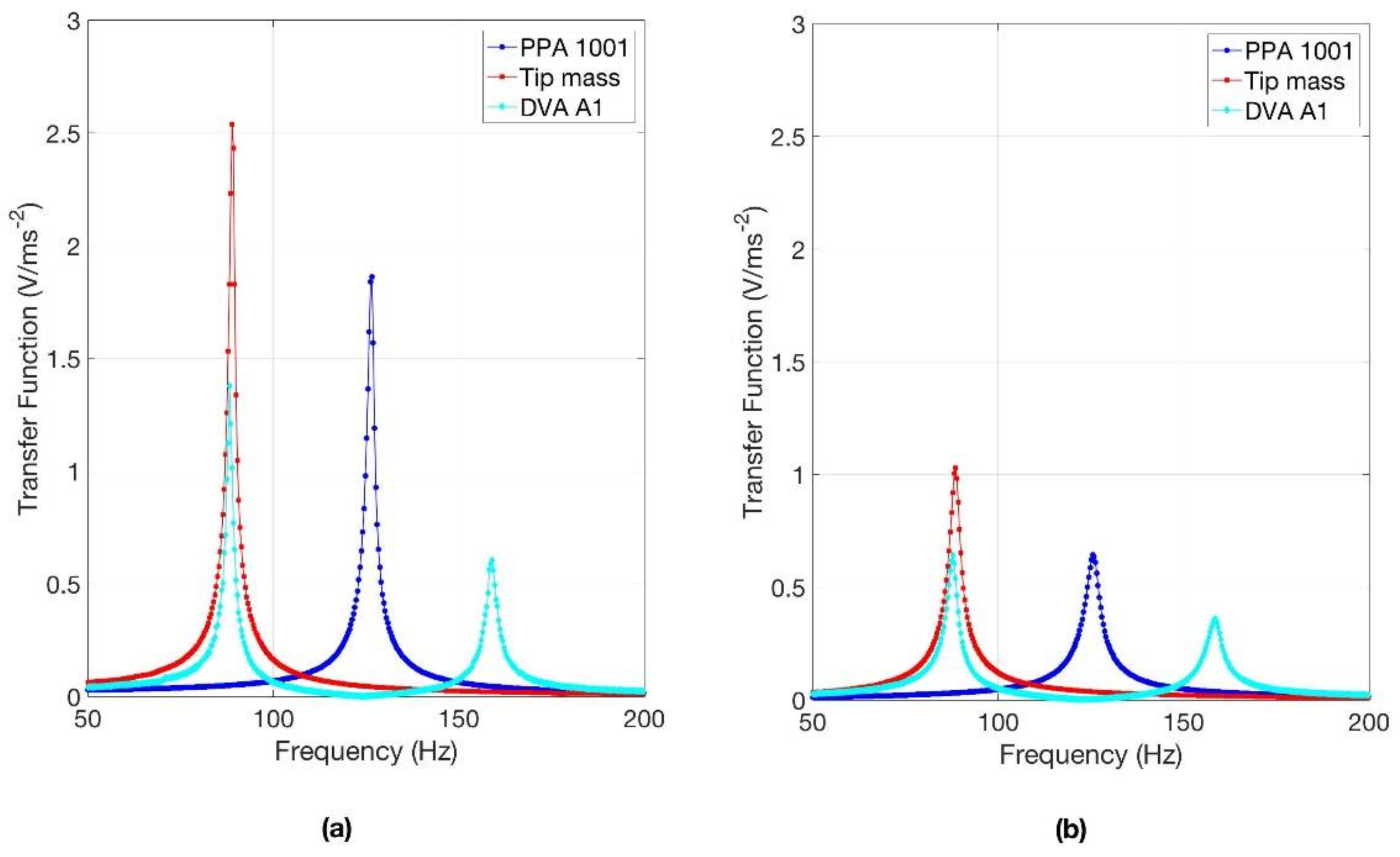
Figure 8a shows an example of measured results. Three configurations are considered: harvester PPA 1001 alone, harvester PPA 1001 with A1, and harvester PPA 1001 with a tip mass.
As foreseen by the analytical model, the introduction of the cantilever DVA splits the original resonance peak into two new peaks, the former at lower frequency, the latter at higher frequency. The amplitude of the first peak is slightly lower than the amplitude of the original peak,
Table 2 shows that it increases if the mass of the DVA increases. The amplitude of the second peak is about 1/3 of the one of the original peak and it decreases if the mass of the DVA increases. The frequency interval (
) between the two peaks increases when the mass of the DVA increases. The comparison between
Table 1 and
Table 2 highlights that the analytical model, which considers only one mode of vibration of the cantilever with DVA, predicts with sufficient accuracy the behavior of the harvester with DVA, therefore in the next future this simple model will be used for optimization purposes.
Modal damping was calculated by means of the half-power-points method [
38]. Results, which are summarized in
Table 2, highlight that the damping ratio
ζ of the first mode of vibration of the coupled system is essentially equal to the one of the fundamental mode of the harvester alone.
The FRFs of
Figure 8a show that harvester with cantilever DVA has two modes of vibration that can be excited by a uniform distribution of base acceleration. Conversely, even if the range of frequency of the FRF is extended, harvester PPA 1001 alone shows only a very small peak at 763 Hz caused by the excitation of the second bending mode.
From the point of view of trimming, the cantilever DVA is able to lower the frequency of the main resonance peak by some tens of Hz. It should be noted that the same effect of the cantilever DVA can be obtained by means of a tip mass.
Figure 8a shows that with a tip mass of 0.591 g (much larger than the one of A1) the natural frequency is roughly equal to the first natural frequency of PPA 1001 equipped with A1. With this solution the generated voltage is larger, but the stress inside the piezoelectric material increases as well.
The same series of measurements was carried out considering for each harvester configuration the optimal load resistance for the first resonance peak at frequency
, which is given by Equation (15).
Figure 8b shows an example of the experimental results. In all the cases here considered the amplitudes in resonance are significantly lower than the ones in open circuit condition due to the effect of the resistance [
6]. The resonance frequency of PPA 1001 and of PPA 1001 with tip mass slightly decreases passing from the open circuit condition to the optimal resistance condition; this result is in agreement with [
6,
37] and the analytical results. In the harvester equipped with DVA the introduction of the optimal resistance lowers the frequency of the first resonance peak by about 1 Hz and has a very small effect on the frequency of the second peak. Therefore, the frequency shifts caused by the cantilever DVAs in the presence of optimal load are similar to those of
Table 2.
The power (
) generated by the harvester in resonance can be calculated from the voltage (
) measured in loaded condition:
is the FRF measured in loaded condition.
If base acceleration is set to 10 ms−2, harvester PPA 1001 generates in resonance 1.61 mW, whereas harvester PPA 1001 with A1 generates 0.97 mW at the first resonance and 0.37 mW at the second resonance.
5. Numerical Model and Validation
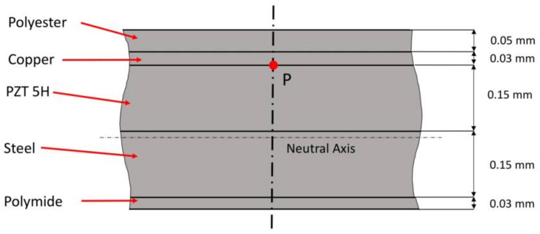
The PPA 1001 unimorph cantilever is composed of five layers of different materials, see
Figure 9. The active layer is made of PZT 5H (0.15 mm), it is partially covered by a copper electrode (0.03 mm) and by a polyester layer (0.05 mm). The structure is an AISI 304 stainless-steel layer (0.15 mm), the bottom layer is made of polymide (0.03 mm).
A numerical FE model was developed with the COMSOL software (Version 5.2, COMSOL Inc., Burlington, MA, USA, 2015). The piezoelectric material was modeled as transversely isotropic linear elastic material with a polarization axis perpendicular to the layer. The other materials were simulated as linear elastic materials with isotropic properties. The characteristics of the harvester’s materials can be found in [
39]. A mapped mesh of second order hexahedral elements with 27 nodes was used. The piezoelectric layer was modeled by means of 5 elements in the thickness direction and by 30 elements and 10 elements in the direction of length and width respectively. Geometrical details, like the edges of the structural material that surround the piezoelectric material, were taken into account.
The steady-state harmonic response was calculated in the multi-physics domain, which includes mechanical, electrostatic, and electrical equations. In the simulations, a hysteretic damping model with
η = 2ζ = 0.017 (where
ζ is damping ratio) was used, in agreement with the experimental results of
Table 2.
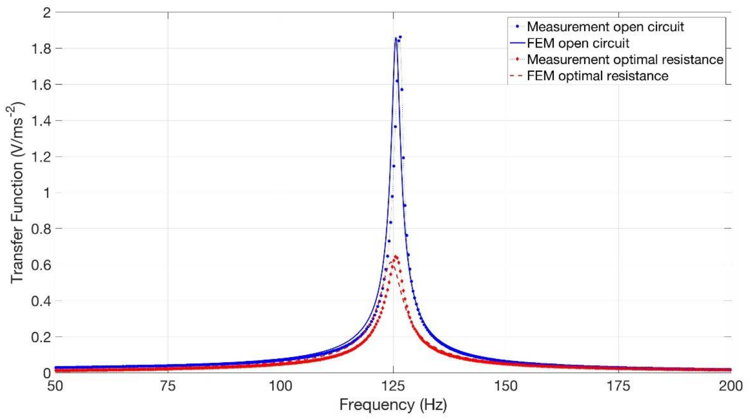
First, the numerical model was validated by comparing the numerical FRFs between generated voltage and base acceleration with the experimental FRFs. Both open circuit condition and optimal load resistance were considered.
Figure 10 shows very small differences both in the values of the resonance frequency and in the values of the resonance peak. In open circuit condition the numerical resonance peak is 1.82 V/ms
−2 and takes place at 125.6 Hz, the experimental values being 1.85 V/ms
−2 at 126.4 Hz. With optimal load resistance (12.7 kΩ) the numerical resonance peak is 0.60 V/ms
−2 and takes place at 124.5 Hz, the experimental values being 0.64 V/ms
−2 at 125.6 Hz.
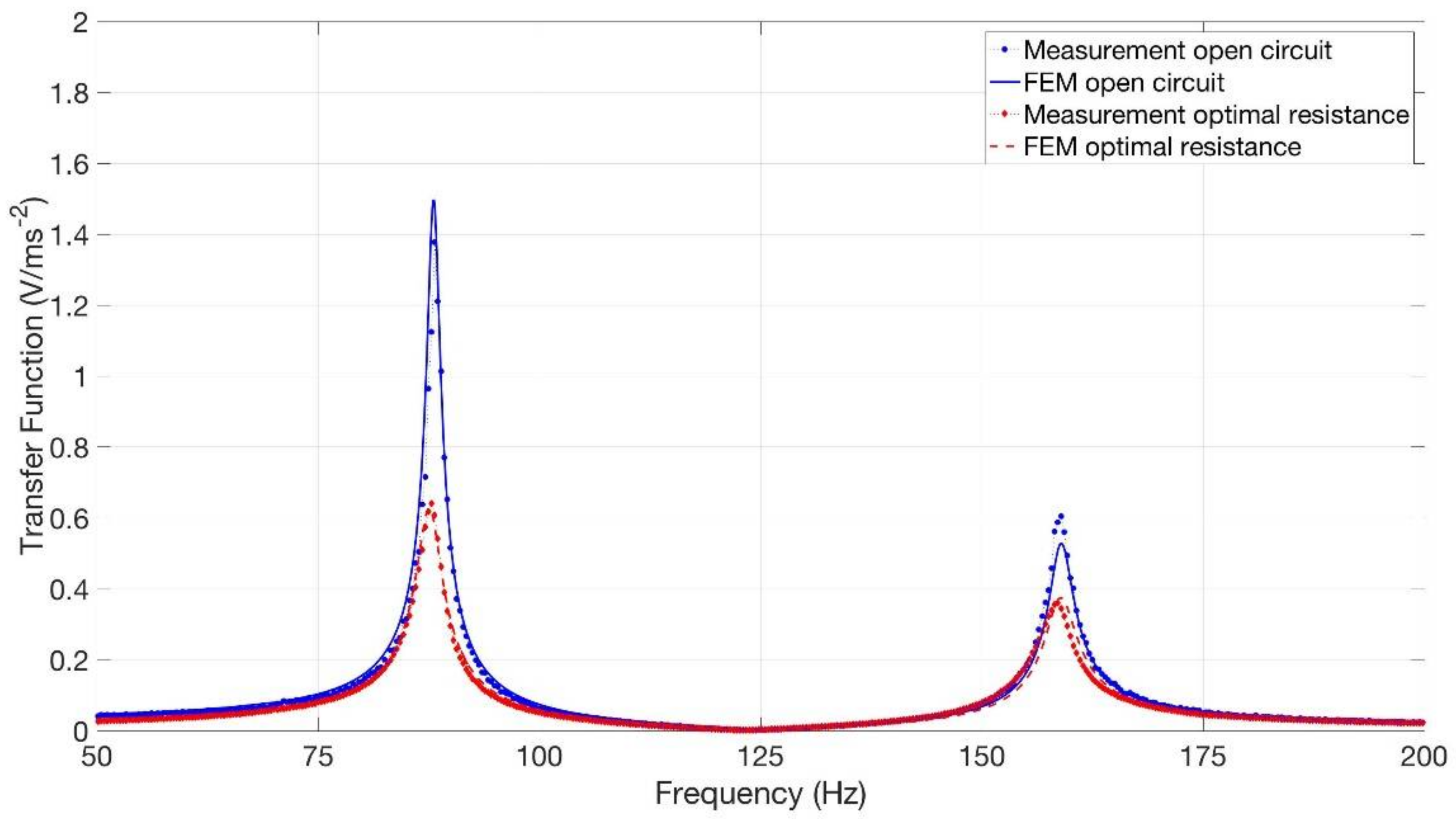
Then, the numerical model was extended in order to simulate the harvester equipped with A1. A beam of hexahedral elements simulated the steel wire of A1 and a lumped mass simulated the brass disk.
Figure 11 shows both the numerical and experimental FRFs between generated voltage and base acceleration of PPA 1001 equipped with A1. In open circuit condition there is a small difference (about 7%) in the height of the first resonance peak. With optimal load resistance the difference is smaller.
6. Numerical Simulation of Harvesters with ITDs
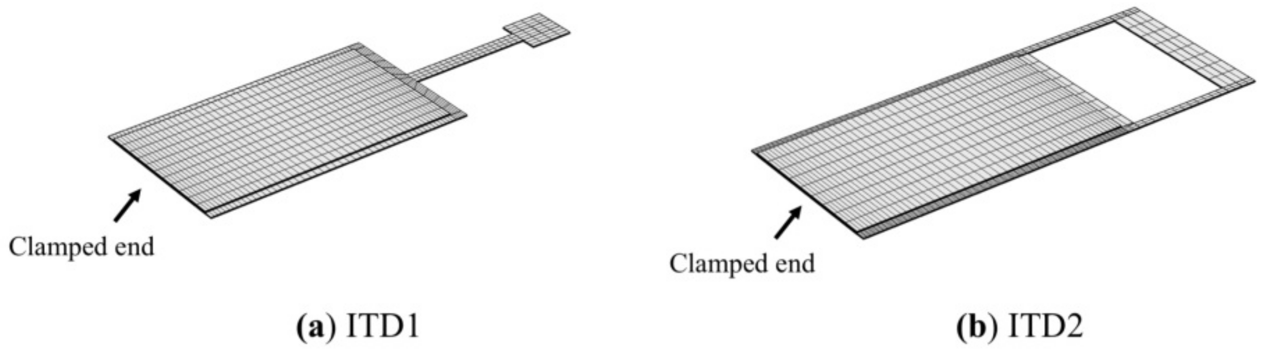
The prototypes were built with a simple technology, which is not suited to mass production. After the validation of the numerical model, the FE analysis was used for predicting the performances of trimming devices integrated with the harvester structure (ITDs). The ITDs were built by extending and shaping the structural layer of PPA 1001. The first design, which is named ITD1, is a development of the tested prototypes (
Figure 12a). In this case the cantilever beam of the DVA is a narrow extension of the structural layer of the harvester, having width
b = 2.16 mm and length
= 21.4 mm. The tip mass is a square patch of structural layer having a side length of 6.5 mm, the mass is 0.05 g. Evidently, ITD1 is a 3D structure and the tip mass cannot be considered a point mass. The analytical model can give only a rough approximation of the behavior of this device, nevertheless, Equations (1)–(3) were used for obtaining a first indication of trimming frequency.
The second design, which is named ITD2, is represented in
Figure 12b. In this case the structural layer is extended for 23.5 mm and then a rectangular hole is made. It is worth noticing that this shape could be obtained by means of a simple manufacturing process. The two lateral sides of the rectangular hole are two cantilever beams, whereas the final edge of the rectangular hole is the tip mass. This mass (0.12 g) is larger than the one of ITD1, because ITD2 is designed in order to show the possibility of trimming the harvester to two harmonics of ambient vibrations. This possibility is useful in the presence of periodic vibrations.
In the remainder of the paper, the results dealing with ITD1 and ITD2 are presented, but other kinds of ITDs were conceived of and simulated in the framework of this research.
6.1. Open Circuit Voltage
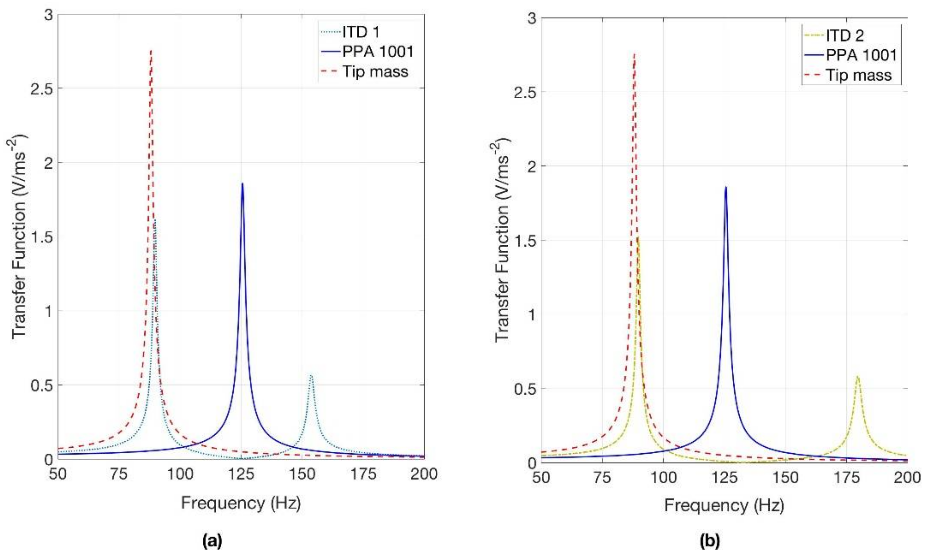
First, the FRFs of the harvesters equipped with ITDs were calculated to assess the trimming capabilities of the ITDs. The open circuit condition was considered, since analytical results and experimental tests on prototypes showed that the resistive load causes only minor frequency shifts of the peaks.
Figure 13a shows that ITD1 trims the main resonance to 89.7 Hz with a peak value (1.6 V/ms
−2), a bit smaller than the PPA 1001 alone. The second resonance peak, which appears at 154.0 Hz, is much lower than the main peak and is caused by the excitation of the second mode of vibration generated by ITD1. For comparison,
Figure 13a shows the effect of a large tip mass (0.59 g). In this case the trimming frequency is 88.1 Hz and the peak value is 2.7 V/ms
−2.
Figure 13b shows that ITD2 is able to lower the frequency of the main resonance peak to 89.7 Hz and to create a second resonance peak at double frequency (179.5 Hz). The heights of the two peaks are 1.5 V/ms
−2 and 0.57 V/ms
−2 respectively.
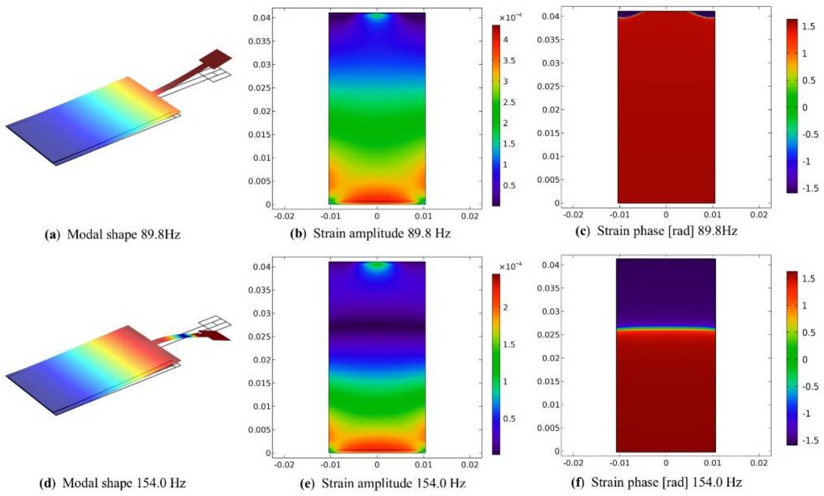
When the frequency of base excitation coincides with one of the resonance frequencies and the deformed shape is dominated by the mode of vibration excited in resonance, the strain distribution inside the PZT layer gives useful information about the effect of the ITD on the harvester.
Figure 14 shows the strain in the upper plane of the PZT layer of the harvester with ITD1. Edges of structural material surround this active layer. The strain component in the longitudinal direction is represented, since it is the most important strain component caused by harvester bending. The color maps show both the amplitude and phase of strain. Strain node lines [
37], which are the lines on the surface of the PZT layer where the strain changes sign, are represented by light lines in the phase plots.
At the first resonance the ITD moves in phase with the harvester. The amplitude of strain decreases rather regularly from the clamped-end to the free-end. There are changes in the sign of strain near the corners of the free-end of the layer. This is a 3D effect, since the ITD is attached at the middle of the free-end of the harvester, see
Figure 12a. With this strain distribution cancellations in generated voltage [
37] are very small and the first peak is high. At the second resonance the ITD moves in phase opposition with respect to the harvester tip (
Figure 14d). The strain distribution in this condition is very different with a strain node line at about 6/10 of the harvester’s length. There is a partial cancellation in the generated voltage, which leads to a small resonance peak.
The strain distributions in the PZT layer of the harvester equipped with ITD2 are represented in
Figure 15. At the first resonance there is only a strain node line near the central part of the free-end of the layer, because the ITD is attached to the harvester in correspondence of the side edges of structural material that surround the active layer (
Figure 15a). Owing to the presence of this strain node line, a cancellation in the generated voltage takes place, but this effect is small, because the negative strain area is small and negative strains have small amplitudes. When the harvester with ITD2 is excited at the frequency of the second resonance peak, the side beams of ITD2 alter the strain distribution inside the PZT layer and there is a partial cancellation in generated voltage.
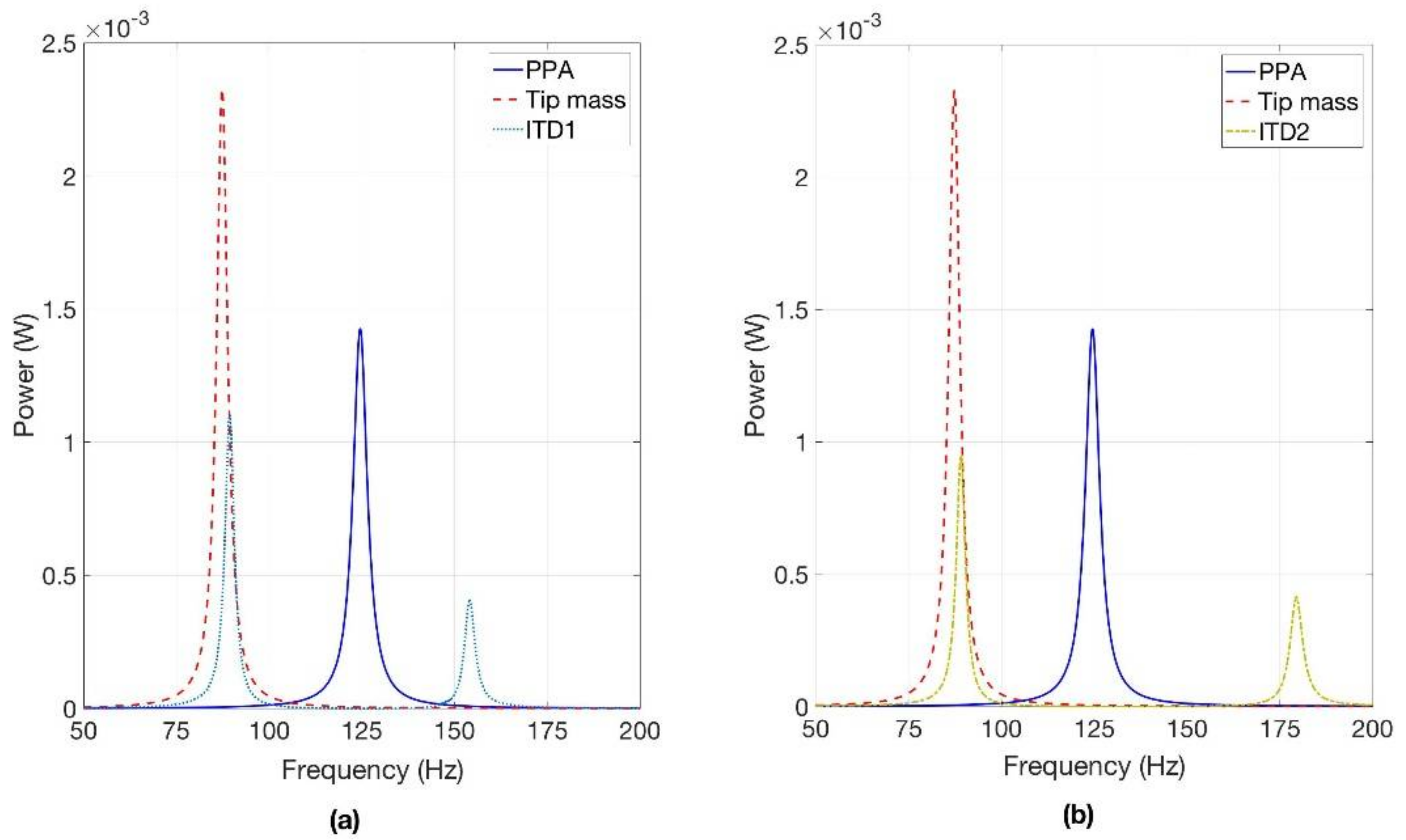
6.2. Generated Power
The most important characteristic of a piezoelectric harvester is the power that it can generate at the various frequencies. In order to calculate the generated power, load resistance was set equal to the optimal value for the first resonance peak Equation (15). The harmonic response with a base acceleration of 10 ms
−2 was simulated. Calculated results are represented in
Figure 16, and the powers generated by the harvesters with ITDs are compared with the powers generated by the harvester alone and by the harvester with a tip mass that trims the harvester to the same frequency.
The power generated by the harvester with ITD1 at the low frequency resonance (89.3 Hz) is 1.10 mW. This value is lower than the power generated by PPA 1001 alone at 124.5 Hz, however, the harvester with ITD1 generates 0.41 mW in correspondence of the high frequency resonance (154.0 Hz).
The harvester with ITD2 is suited to operate in the presence a periodic excitation with the first harmonic at 89.5 Hz (fundamental frequency), because it generates 0.95 mW at the fundamental frequency and 0.42 mW at the frequency of the second harmonic.
Finally, the harvester with tip mass generates the largest power at 87.3 Hz.
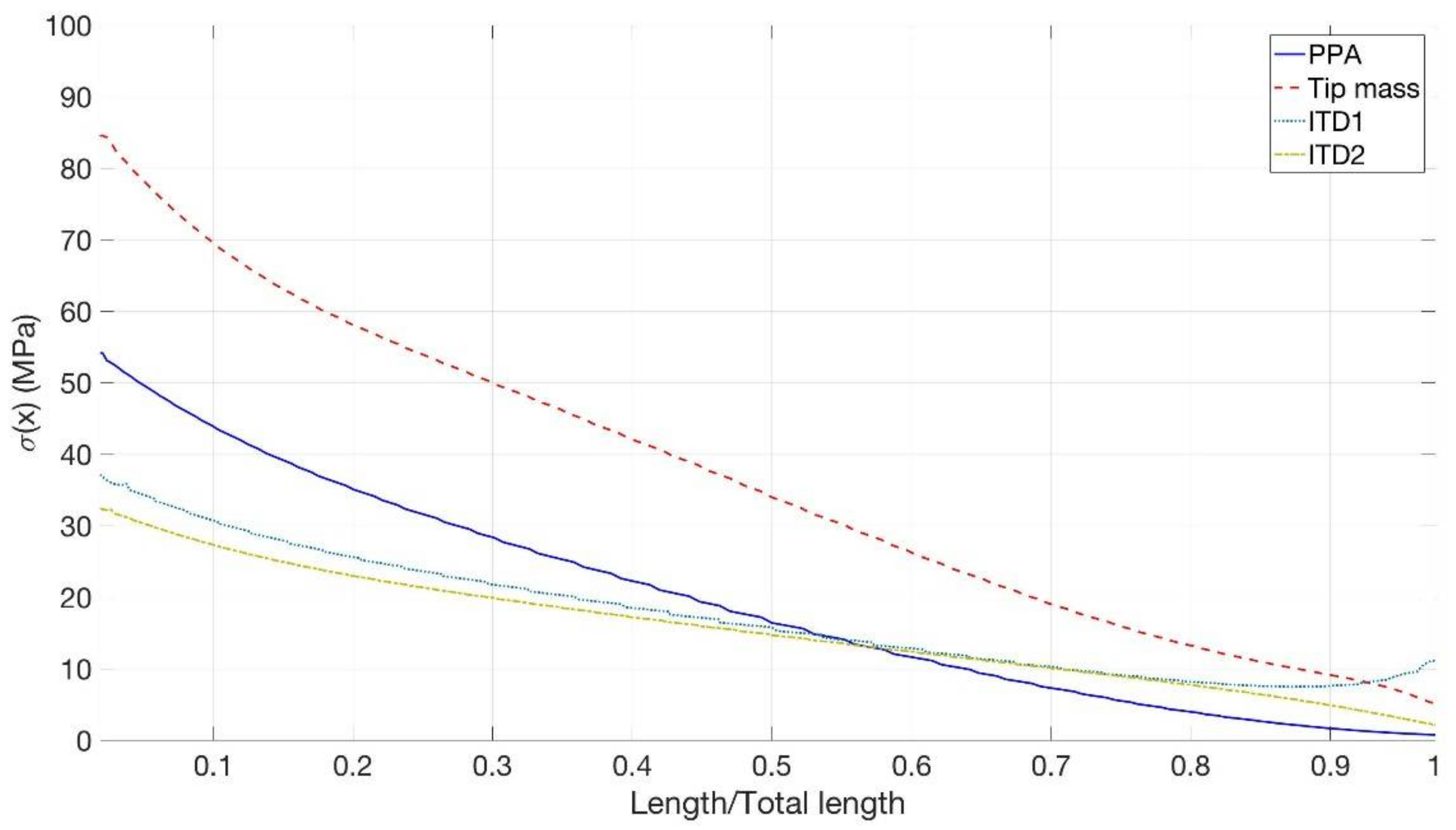
6.3. Stress Analysis
The last numerical analysis here presented deals with the stress analysis inside the piezoelectric material. Four configurations were considered: harvesters equipped with ITD1 and ITD2, PPA 1001 alone and with tip mass. The harvesters were excited by a base acceleration of 10 ms−2 at the main resonance frequency, which coincides with the low frequency peak of the harvesters with ITDs and with the main peak of the others.
Normal stress in the longitudinal direction
σx was calculated, since it is the most important stress component caused by harvester bending. Stress
σx was evaluated along the centerline of the upper surface of the PZT layer, which is at the largest distance from the neutral axis of the composite cross-section. The trace of this line is point P of
Figure 9.
Figure 17 shows that the introduction of the tip mass does not considerably modify the trend of stress distribution along the span of the harvester, which is characterized by the largest values near the clamp. But the tip mass leads to a large increase in the values, which almost double. Conversely, when ITD1 is introduced, the trend of stress distribution along the span of the harvester changes. In particular, the stress decreases less when moving from the clamp to the tip of the harvester and it increases sharply in the proximity of the connection with the ITD. The maximum value is reached at the clamp and it is smaller than the one of PPA 1001 alone. The insertion of ITD2 lowers the stress at the clamped-end as well, but with ITD2 the stress near the free-end of the PZT layer increases less than with ITD1, since ITD2 is connected to the harvester in correspondence of the side edges of the structural layer that surround the PZT layer, see
Figure 12b.
It should be noted that the bending breaking strength of PZT 5H is in the range 100–140 MPa [
40,
41] and it considerably reduces in the presence of cyclic loading (see Figure 3 of [
41]). Hence, with high acceleration levels the harvester with tip mass may be closer to the failure condition than the harvester with ITDs.
7. Discussion
The introduction of an ITD chiefly has two effects on the harvester’s performance: the lowering of the main resonance frequency and the appearance of a new resonance peak that can be exploited in order to harvest energy
The first effect could be achieved by adding a tip mass, but the tip mass is much larger than the ITD mass and it leads to a large increase in the inertia forces. This fact increases the generated power (
Figure 16) but also the stress inside the piezoelectric layer (
Figure 17). Hence, an ITD is useful for trimming a harvester when the vibration levels are high and the stress inside a harvester equipped with a tip mass could reach dangerous values.
The lowering of the resonance frequency could also be attained by adjusting the geometric and inertial parameters of the harvester without inserting an ITD. The basic theory of vibrating beams [
23] shows that this effect could be attained by increasing the length and decreasing the width of the rectangular cantilever harvester (slender harvester), but the results of numerical simulations (
Table 3) show that the stress near the clamped end increases. The reduction in the equivalent bending stiffness of the composite cross section could reduce the natural frequency, but also in this case the harvester becomes rather weak and it could be plastically deformed and/or damaged during manipulations. Another possibility is the modification of the shape of the harvester, even if the deposition of the various layers on a non-rectangular base could lead to practical problems. To make a comparison an inverse-tapered harvester [
42] having the same cross section and the same volume of piezo material as PPA 1001 was investigated. Numerical results, which are reported in
Table 3, highlight that also in this case there is a large increase in stress near the clamped end.
The second effect of the ITDs (the presence of two resonance peaks) presents some limits and some potentialities as well. The main limit is the large frequency interval
between the peaks (64 Hz in ITD1). Therefore, the harvesters with these ITDs cannot be considered broadband harvesters. The analytical model and experimental results on the prototypes (
Table 2) actually show that
can be decreased by decreasing the mass of the trimming device, nevertheless, it is rather difficult to obtain two close peaks (
< 10 Hz). The potentialities of the harvesters with ITDs are related to the fact that periodic excitation with relatively large frequency intervals between the harmonic components is rather common in machines. Typical examples of periodic excitation can be found in rolling bearings [
43], electrical machines [
43], piston machines [
44] (engines and compressors), fans and blowers [
43] (harmonics of the blade passing frequency), and in geared systems [
45] (harmonic of the mesh frequency). In these cases, the harvesters with ITD can be trimmed to a couple of sharp and stable peaks that are characteristic of the spectra of these sources of excitation. Numerical simulations show that ITD2 can be trimmed to 90 Hz and 180 Hz with an overall harvested power of 1.37 mW.
8. Conclusions
Analytical calculations and experimental results show that it is possible to develop cantilever DVAs that behave as reactive mechanical loads and that are able to modify the natural frequencies and modes of vibration of the harvester, without significantly increasing the damping of the system.
Usually, vibration energy is available at frequencies lower than the fundamental frequency of a piezoelectric harvester. Experimental results show that decrements in the fundamental frequency of about 30% can be achieved by means of a simple cantilever DVA.
These concepts, which have been validated by means of prototypes built with a simple technology, are then extended to develop the ITDs. The integration of the trimming device with the structural layer of the harvester is a promising technology, since the extension of the structural layer (steel or plastic material) would be rather inexpensive and the extension could be cut into the desired shape by means of consolidated technologies, such as punching or laser cutting. The harvester with ITD appears simpler and cheaper than other promising solutions.
In the framework of this research the potentialities of harvesters equipped with ITDs have been investigated by means of FE simulation. Numerical results show that the ITDs basically have the same properties of the cantilever DVA, but some different designs are possible, which correspond to different performances of the harvester.
The first integrated trimming device (ITD1) is suited to lower the natural frequency of the harvester of about 35 Hz and to collect power at low frequency (1.1 mW). The second integrated trimming device (ITD2) is characterized by two resonance peaks with multiple frequencies and it is suited to collect energy from periodic excitation.
The main limit of an ITD seems the increased length of the device, but this limit could be overcome with a folded design in which the mass lies near the harvester base.
Future research directions are testing and numerical simulation of harvesters equipped with more complex ITDs, which behave as dynamic systems with many DOFs.


