Abstract
This paper considers a hybrid relay network consisting of the source, the amplify-and-forward (AF) relay, the decode-and-forward (DF) relay, and the destination. In hybrid three-hop relay systems, the transmitted signal from source can be received at the destination after processing the signals through two relays. If the first relay amplifies and forwards the received signal, and the second relay decodes and forwards the received signal, the system model is considered to be an AF-DF relay system. The reverse case is considered for the DF-AF relay system. The AF-DF and DF-AF relay systems have different error rates and achievable throughput with respect to the channel conditions between two nodes. We propose optimal power allocation schemes for two different relays in order to maximize the achievable rate under a sum relay power constraint for given channel gains and transmit power from the source. By solving the optimization problem to maximize the achievable rate for each relay network, the transmit power values in closed form are derived. When the channel gains are the same, the optimal power allocation scheme for the AF-DF relay network proves that greater power should be allocated at the first relay to maximize the achievable rate. In the case of the DF-AF relay network, we derive an optimal power allocation scheme for the four possible cases. Under the same signal-to-noise ratio (SNR) condition, at the first hop we show that the achievable rate of the AF-DF relay network is greater than that of the DF-AF relay network when the channel gain between two relays is greater than that between the second relay and destination. Simulation results show that the proposed power allocation schemes provide a higher achievable rate than the equal power allocation scheme and the grid search schemes.
1. Introduction
Cooperative communication has recently received much attention as a method to improve network performance [1,2,3,4,5,6,7,8,9,10,11]. In multi-hop cooperative communications, the source transmits signal to relays that forward signals to the destination or other relays.
There are two relaying strategies: amplify-and-forward (AF) and decode-and-forward (DF). In the AF relaying scheme, the relay simply amplifies the received signals from the source and retransmits them to the destination without performing any signal regeneration, which may lead to the propagation of noise and interference. For the DF relaying scheme, a relay decodes the received signals and retransmits the recovered signals to the destination. Although the DF relaying scheme achieves extra coding gain, the error propagation is caused by decoding errors in the relay.
Two-way relay communication schemes are also drawing attention. Since the AF relaying scheme generally provides good spectral efficiency with much lower complexity than the DF relaying scheme, the authors of [10] consider the AF-based two-way relaying networks. In [10], the closed-form weights for distributed beamforming using zero-forcing are derived to cancel the inter-user interference in multi-user two-way AF relay networks. In [11], the performance of multiple AF relay networks is analyzed and investigated in consideration of significant practical issues such as time-selective fading due to node mobility and imperfect channel estimation. In addition, the generic expressions for the destination’s signal-to-noise ratio (SNR), the system average bit error rate, the outage probability, and the capacity are derived in [11].
To obtain the advantages of both the AF and the DF strategies, hybrid relaying schemes are studied in [12,13]. In [12], the authors analyze the bit error probability for both the AF relaying and the DF relaying with respect to SNR and propose a hybrid relaying scheme which changes the relaying scheme based on analyzed bit error probability. As in [12], the authors of [13] calculate the symbol error probability for both homogeneous relaying and hybrid relaying networks, and simulate the symbol error rate (SER) according to the location of the relay. The hybrid relaying schemes in [12,13] have better bit error rate (BER) and SER performance than the simple homogeneous relaying schemes. These hybrid relaying networks obtain more gains than homogeneous relaying schemes.
Recently, the power allocation problem in cooperative systems has been the focus of much research. In [14,15], power allocation schemes are proposed to maximize the capacity under a sum transmit power constraint for AF relay and DF relay, respectively. Optimal power allocation schemes for hybrid networks are analyzed for a two-hop AF and DF cooperative relay system, employing the outage probability as the optimization criterion in [16].
In [17], optimal power allocation based on average end-to-end symbol error probability (SEP) as the optimization criterion is performed for a two-hop DF cooperative relay system. In [18,19], the instantaneous received signal-to-noise ratio (SNR) and its approximate expression are exploited to obtain optimal power allocation for an AF multi-hop relaying system. The optimal power allocation based on outage probability in a DF multi-hop system is discussed in [20]. In [21], the power allocation scheme that minimizes a bit error rate (BER) at the destination for uncoded AF with a Rayleigh fading channel under sum transmit power consumption is proposed. The optimal power allocation strategy is proposed in [22] to maximize achievable secrecy rates under an overall transmit power constraint, assuming that a single relay is located at each individual hop.
In hybrid relaying networks, the error performance is mainly affected by the received SNR, which is changed by the transmit power, channel power, and noise power. This paper proposes optimal power allocation schemes for hybrid relay networks within limited total power. The proposed schemes provide a higher achievable rate than the equal power allocation scheme and can approach the maximum achievable rate with lower power than an equal power allocation scheme. Also, after applying the proposed power allocation schemes, the achievable rates for two hybrid relay networks, i.e., AF-DF and DF-AF, are distinct in accordance with the differences in channel conditions from one relay to another and from the relay to a destination. In other words, the proposed scheme optimizes hybrid relaying of two relay links by selecting a better relaying scheme with optimal power allocation. Optimization for two relay links provides better reliability than optimization of only one relay link.
In inter-cell communication systems, which are more common than intra-cell communication systems, three-hop relaying transmission is sufficient to achieve optimal throughput and to find the optimal relay node [23]. The simulation results in [23] show that three-hop relaying transmission has better throughput performance than two-hop and four-hop relaying transmission. For transmission with the two-hop relaying network, the transmission range is short and this causes a decrease in achievable throughput in the inter-cell communication. Due to the short range, it is more difficult for the two-hop relaying system to select a better relaying node in terms of throughput performance than the three-hop relaying system. Also, for transmission with four or more relaying hops, the throughput can be severely decreased because the routing with four or more relaying hops increases the forwarding delay and causes a greater overhead and signal processing delay for the overall system. Therefore, the number of hops in this paper is confined to three. If more nodes than three are needed due to high path loss, the problem becomes the optimization of general N-hop relaying. If N is larger than three, optimization of general N-hop relaying is inefficient. To avoid the inefficient optimization, the N-hop relaying can be treated as successive optimization of two relay links with the optimization of one relay link.
In [24,25], to increase the channel capacity, cooperative communication systems with high diversity gain and the relay selection are used in consideration of the power allocation. However, because cooperative communication generally has a complicated structure, the following problems occur, as pointed out in [26]. Firstly, a sophisticated scheduler is needed for a large number of nodes, which are used as relays to form complex cooperative communication. Also, an additional overhead is required for channel estimation, synchronization, and security for multiple nodes. However, the proposed schemes improve the channel capacity through optimal power allocation and a hybrid relaying network in accordance with channel conditions without a sophisticated scheduler and additional overhead.
The proposed schemes enable the achievable rate to maximize by adaptively allocating the power to the first and the second relay nodes. For adaptive power allocation of each relay node, we derive the transmit power values in a closed form for each relay network according to the channel condition. Analytical solutions are derived, and the proposed power allocation schemes are compared with the equal power allocation scheme and the grid search schemes. In addition, we compare the achievable rates of the proposed power allocation schemes when the SNR of the first hop is the same. The simulation results show that the proposed optimal power allocation scheme requires lower transmit power to achieve a specific achievable rate than the equal power allocation scheme. Therefore, this paper contributes to a reduction in the lower limit of transmit power consumption to satisfy the achievable rate in cooperative communication. In terms of next-generation systems, green communication has become popular. A reduction in the lower limit of transmit power consumption by the proposed schemes will contribute to the implementation of green communication in next-generation systems.
The remainder of this paper is organized as follows. In Section 2, the system model of hybrid three-hop relay networks is presented. In Section 3, optimal power allocation schemes are proposed for three-hop AF-DF and DF-AF relay networks, respectively. Section 4 shows the simulation results, and the conclusions are drawn in Section 5.
2. System Model
In [23], the comparisons of throughput performance for multi-hop strategies are shown by computational simulation results. The throughput performance for systems with two-hop and four-hop relaying is poorer than for systems with three-hop relaying. The reasons are summarized as follows. First, it is difficult to find the node with the best transmission rate for the two-hop relaying system because of the short transmission range of the ad hoc interface. Also, in systems with more than three hops, there is a greater overhead for the routing or forwarding delay. The three-hop relaying system can greatly facilitate in the inter-cell communication because the node has a high probability of reaching a neighboring base station. Therefore, the number of hops in this paper’s relay network is confined to three.
Figure 1 shows the system model consisting of a source s, the first relay , the second relay , and a destination d. The nodes operate in the half-duplex mode, i.e., they are not able to receive and transmit at the same time and same frequency. We assume that the transmit time from one node to another node is the same. In addition, we assume that there is no delay for processing the signal in AF and DF relays. In hybrid three-hop relay systems, the transmitted signal from source can be received at destination after processing the signals at two relays. If the first relay amplifies-and-forwards the received signal and the second relay decodes-and-forwards the received signal, the system model is considered as the AF-DF relay system. On the other hand, if the first relay decodes-and-forwards the received signal and the second relay amplifies-and-forwards the received signal, the system model is considered as a DF-AF relay system. The AF-DF and DF-AF relay systems have distinct error rates and achievable throughput in accordance with the different channel conditions between two nodes.
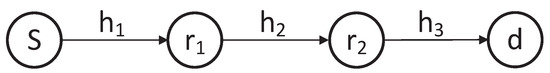
Figure 1.
A hybrid three-hop relay network.
We assume that the channel gains are acquired from channel state information (CSI) of a system by using a reference signal (RS) of the 3rd Generation Partnership Project (3GPP) Long Term Evolution (LTE) and all relays in the system are aware of the used power for the transmission of a signal. In the case of three-hop relay network, three RSs should be allocated and the destination provide feedback on the CSI through reverse links of the relay network. For channel estimation, various schemes can be considered [27,28]. However, a perfect CSI is assumed to compare the maximum performance with other power allocation schemes. In addition, it is assumed that the total power for relaying is fixed. Since the relays also need power to transmit their own signal, this condition is necessary. In the case of an equal power allocation scheme, the fixed total power is equally allocated to all relays. However, since channel condition is not of concern, the equal power allocation scheme inefficiently allocates the power resource between relays. Therefore, the optimization procedures should be applied for system power efficiency. This fixed total power can be normalized for comparison with other power allocation schemes [24,25].
The purpose of hybrid relay network is to achieve both high throughput performance and simple implementation. The different properties in AF-DF and DF-AF relay networks result in these two schemes showing different performance with respect to achievable throughput and implementation, in accordance with channel conditions. Generally, because the AF scheme severely amplifies the noise power, the error performance for the AF scheme is poorer than that of the DF scheme. The error performance of the AF scheme is almost the same as that for the DF scheme when the channel condition is good. However, because the DF scheme always knows the channel state information (CSI) needed to decode the received signals, one of main disadvantages for the DF scheme is that the real-time implementation is more difficult than in the AF scheme for the multi-hop transmission system. The AF scheme which simply amplifies the received signal does not require CSI. The AF-DF scheme is adequate when the communication link between the source and the first relay is good, with simple implementation by amplifying the received signal, and has high throughput performance when a communication link between the first relay and the second relay is not good. Also, the DF-AF scheme has high throughput performance when the communication link between the source and the first relay is not good and is adequate when the communication link between the first relay and the second relay is good, with simple implementation. In this paper, both AF-DF and DF-AF system models are represented for general analysis of hybrid relay network in various channel conditions.
2.1. The AF and DF Relay Network
In this subsection, we assume that the first relay considers the AF protocol and the second relay considers the DF protocol.
In the first time slot, the source transmits the signal with transmit power to the first relay. The received signal at the first relay can be expressed as
where is the channel coefficient from source to the first relay and is the zero-mean additive white Gaussian noise (AWGN) with unit variance at the first relay.
In the second time slot, the first relay transmits the signal with transmit power to the second relay. The transmitted signal at the first relay is
where is the amplification factor for the AF relay, which can be calculated by using the amplifier gain formula in [29] as
The received signal at the second relay can be expressed as
where is the channel coefficient from the first relay to the second relay and is the zero-mean AWGN with unit variance at the second relay. The second relay decodes the received signal. In the third time slot, the second relay transmits the signal with transmit power to the destination. The received signal at destination can be expressed as
where is the channel coefficient from the second relay to the destination and is the zero-mean AWGN with unit variance at the destination.
By using Shannon’s formula in [30], the achievable rate can be obtained as
where is the SNR for the AF-DF relay network and is given by
In other words, the SNR for the AF-DF relay network is determined by the minimum values between the harmonic mean of SNRs from the source to the AF relay and from the AF relay to the DF relay, and the SNR from the DF relay to the destination.
2.2. DF and AF Relay Network
In this subsection, we assume that the first relay considers the DF protocol and the second relay considers the AF protocol. In the first time slot, the source transmits the signal with transmit power to the first relay. The received signal at the first relay can be expressed as
where is the channel coefficient from source to the first relay and is the zero-mean AWGN with unit variance at the first relay.
The first relay decodes the received signal. In the second time slot, the first relay transmits the signal with transmit power to the second relay. The received signal at the second relay can be expressed as
where is the channel coefficient from the first relay to the second relay and is the zero-mean AWGN with unit variance at the second relay.
In the third time slot, the second relay transmits the signal with transmit power to the destination. The transmitted signal at the second relay is
where is the amplification factor for AF relay and is given by
The received signal at the destination can be expressed as
where is the channel coefficient from the second relay to destination and is the zero-mean AWGN with unit variance at the destination.
By using Shannon’s formula in [30], the achievable rate can be obtained as
where is the SNR for the DF-AF relay network and is given by
In other words, the SNR for the DF-AF relay network is determined by the harmonic mean between the minimum value of the SNR from the source to the DF relay, and from the DF relay to the AF relay, and the SNR from the AF relay to the destination.
3. Optimal Power Allocation Schemes for Hybrid Relay Networks
We propose optimal power allocation schemes for hybrid three-hop relay networks which maximize the achievable rate under a sum relay power constraint for given channel gains and transmit power from the source.
3.1. AF and DF Relay Network
In this subsection, we propose the optimal power allocation scheme for the three-hop AF and DF relay networks.
The optimization problem to maximize the achievable rate under a sum relay power constraint can be written as
We define the ratio of to P as . By using , the optimization problem is rewritten as
where and are given, respectively, as
As increases, increases and decreases. Therefore, by solving the equation and using the well-known quadratic formula, the optimal is obtained as
where a, b, and c are given, respectively, as
From Equation (21), we know that is greater than . In other words, we should allocate more power to the first relay than the second relay to maximize the achievable rate when the channel gains are the same. In addition, we know that increases as P increases, as per Equation (21). Therefore, greater power should be allocated at the first AF relay, as P increases when the channel gains are the same.
When , the SNR for the AF-DF relay network in Equation (7) is rewritten as
where and are given, respectively, as
Because has a similar form of the harmonic mean of and , the increment of is less than that of as increases. On the other hand, the increment of is equal to that of as increases. Therefore, the increment of is less than that of when the increments of and are the same. To maximize the minimum value between and in Equation (23), it is necessary to further increase , which does not increase as much as . In addition, to increase more than , we should allocate more power at the first relay than at the second relay.
3.2. The DF and AF Relay Networks
In this subsection, we propose the optimal power allocation scheme for the three-hop DF and AF relay network.
The optimization problem to maximize the achievable rate under a sum relay power constraint can be written as
We define the ratio of to P as . By using , the optimization problem is rewritten as
where is given as
To determine in Equation (28), we take into account two cases as follows.
3.2.1. Case a ()
We define as
When , we can obtain the relation . Therefore, is determined as . In addition, when , we can obtain the relation . Hence, is determined as . In other words,
Firstly, we consider Case a(1) when .
By using Equation (30), the optimization problem in Equation (27) is rewritten as
where and are given by
Taking a partial derivative of Equation (32) with respect to and equating it to zero, we can obtain , which maximizes as
where .
The increases for and decreases for . Since is less than zero, decreases as increases for . As a result, the optimal is when and when .
Secondly, we consider Case a(2) when .
By using Equation (30) and , the optimization problem in Equation (27) is rewritten as
where and are given by
By solving the equation , we know that has a maximum value when . Therefore, increases for and decreases for . Since is less than zero, decreases as increases for . As a result, the optimal is when and when .
Figure 2 shows the possible cases of in Case a.
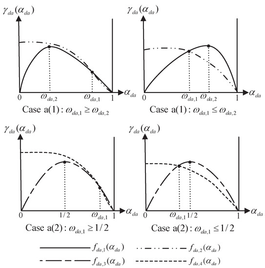
Figure 2.
Possible cases of in Case a for the DF-AF relay network. DF: decode-and-forward; AF: amplify-and-forward.
3.2.2. Case b ()
Since , we can derive the relation . Therefore, in Equation (28) is determined as .
Firstly, we consider Case b(1) when .
By solving the equation , the optimal is obtained as
where .
From Equation (34), we know that is the same as .
Secondly, we consider Case b(2) when .
By using , the optimization problem in Equation (27) is rewritten as
where is given by
By solving the equation , the optimal is obtained as .
The algorithm in Figure 3 explains the procedure to determine for the DF and AF relay network.
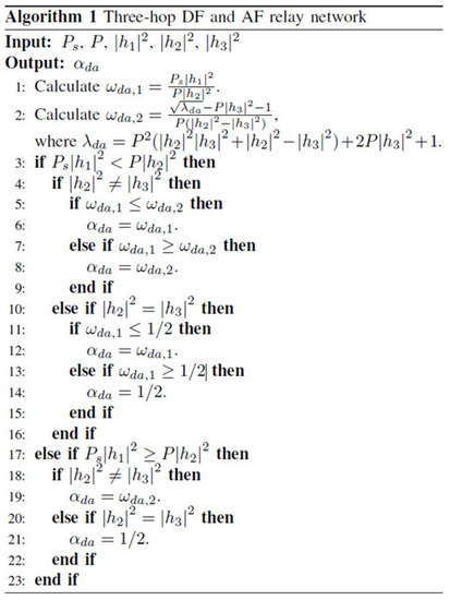
Figure 3.
Algorithm for the three-hop DF and AF relay networks.
Figure 4 shows the flow chart of full procedures to illustrate the proposed optimal power allocation schemes.
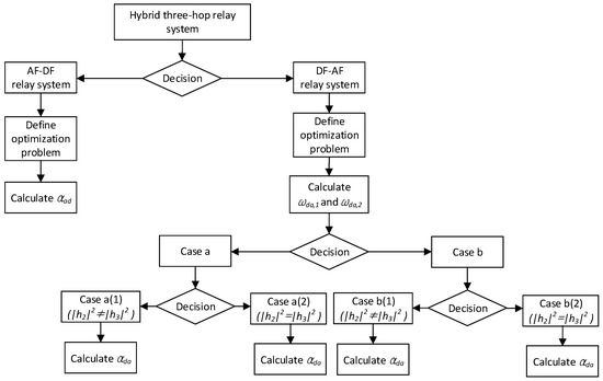
Figure 4.
Flow chart of the proposed optimal power allocation schemes.
From Equations (19) and (20), the complexity of finding in AF-DF relay network can be determined as . The represents the operation of multiplication or division. The operation of addition, subtraction, or comparison is expressed as O. From the algorithm for the DF-AF relay network in Figure 3, the complexity to find can be calculated as . Because the proposed optimal power allocation schemes provide the closed form-based formula, the complexity of the proposed schemes is much less than for the grid search schemes. The grid search schemes find the and that enable to maximize the achievable rate by changing the values of and at a fixed interval or step size in the range of 0–1, respectively.
In this paper, we consider the values of and as the step sizes. From Table 1, we know that the grid search schemes with step size and have much higher complexity than the proposed schemes because they perform exhaustive search procedures. Therefore, the proposed optimal power allocation schemes provide not only low complexity but also optimal performance.

Table 1.
Complexity of proposed and grid search schemes to find and .
4. Simulation Results
This section presents the achievable rates of the proposed power allocation scheme, grid search schemes with step sizes and , and the equal power allocation scheme for hybrid three-hop relay networks. For the equal power allocation schemes, and are fixed to . Also, we assume that any delay components made in relays are removed perfectly and are ignored.
Figure 5a,b shows the achievable rates and for the AF-DF relay network when dB. From Figure 5a, it is observed that the achievable rate of the optimal power allocation scheme is greater than for the grid search schemes and the equal power allocation scheme regardless of channel gains. The grid search scheme with step size shows the performance close to the optimal power allocation scheme because this scheme can precisely find in unit which maximizes the achievable rate. Since the grid search scheme with can find in only units, it is more difficult to find the that provides optimal performance. As shown in Figure 5b, the difference of between the optimal power allocation and the grid search scheme becomes larger as the step size becomes larger. Therefore, the grid search scheme with shows poorer performance than that with . In Table 2 and Table 3, we show and compare the values of achievable rate for power allocation schemes when dB. From Table 2 and Table 3, the optimal power allocation scheme shows the best performance and the equal power allocation scheme shows the worst performance. In addition, the grid search scheme with shows a better performance than with . Among the results in Figure 5a, the achievable rates expressed by the dashed line for optimal power allocation and equal power allocation converge after the power constraint of 10 dB. This can be understood from Equations (17) and (18). After the power constraint of 10 dB, the of the two allocation schemes is determined by Equation (17) and is hardly subject to .
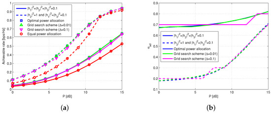
Figure 5.
Performance for the AF-DF relay network when dB. (a) Achievable rates for the power allocation schemes; (b) for the optimal power allocation scheme and grid search schemes.
Table 2.
Achievable rates for the AF-DF relay network when .
Table 3.
Achievable rates for the AF-DF relay network when and
From Figure 5b, we can know that is greater than when . As mentioned, the SNR at destination is determined by the minimum value between the SNR at the second relay and the SNR of the third hop . In addition, the increment of is less than that of when increments of the transmit power from each relay are the same. To maximize , we need to further increase which does not increase as much as . Therefore, we should allocate more power at the first relay than the second relay to increase more than .
Figure 6a,b show the achievable rates and for DF-AF relay network when dB. Case a(1) and a(2) are described when and , respectively. Then, Case b(1) is described when . From Figure 6a, it is observed that the optimal power allocation schemes for Case a(1) and b(1) provide a higher achievable rate than the grid search schemes and equal power allocation scheme. We show and compare the values of achievable rates for the DF-AF relay system in Table 4, Table 5 and Table 6. The decreases for Case a(1) and increases for Case b(1) as P increases. As mentioned in Case a(2), is for and for . In other words, is for and for . When dB and , is dB. Therefore, as shown in Figure 6b, for Case a(2) is for dB and for dB. The achievable rate of the optimal power allocation scheme for Case a(2) is the same as for the grid search schemes and the equal power allocation scheme when dB. Then, the optimal power allocation scheme for Case a(2) provides a higher achievable rate than the grid search schemes and the equal power allocation scheme when dB.
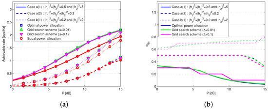
Figure 6.
Performance for the DF-AF relay network when dB. (a) Achievable rates for the power allocation schemes; (b) for the optimal power allocation scheme and grid search schemes.
Table 4.
Achievable rates for the DF-AF relay network in Case a(1): and .
Table 5.
Achievable rates for the DF-AF relay network when Case a(2): .
Table 6.
Achievable rates for the DF-AF relay network in Case b(1): and .
Figure 7a,b show the achievable rates of the proposed power allocation schemes for hybrid three-hop relay networks when the SNR of the first hop is 0 dB, dB, and dB. When has a greater value than , it is observed that the achievable rate for DF-AF relay network is greater than that of AF-DF relay networks regardless of . On the other hand, the achievable rate for the AF-DF relay network is greater than for DF-AF relay networks when has a greater value than . As mentioned, the SNR at destination for the AF-DF relay network is determined as the minimum value between the SNR at the second relay and the SNR of the third hop . Because has a form similar to the harmonic mean between and the SNR of the second hop, the increment of is less than that of when the increments in SNR of each hop are the same. Therefore, to maximize , we need to further increase , which does not increase as much as . For a given , can be increased by increasing . Unlike the AF-DF relay network, the SNR at destination for the DF-AF relay network has a similar form of harmonic mean between and the SNR of the third hop when is less than the SNR of the second hop. For a given , can be increased by increasing . Therefore, has a greater value than when is sufficiently larger than . On the other hand, has a greater value than when is sufficiently larger than .
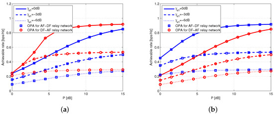
Figure 7.
Achievable rates for the proposed power allocation schemes. (a) and ; (b) and .
Figure 8a,b show the achievable rates of the equal power allocation schemes for hybrid three-hop relay networks when the SNRs of the first hop are 0 dB, dB and dB. As shown in Figure 7a,b, the achievable rate of the DF-AF relay network is greater than for the AF-DF relay networks when has a greater value than and vice versa. It is observed that the achievable rates of the equal power allocation schemes are lower than for the proposed power allocation schemes.
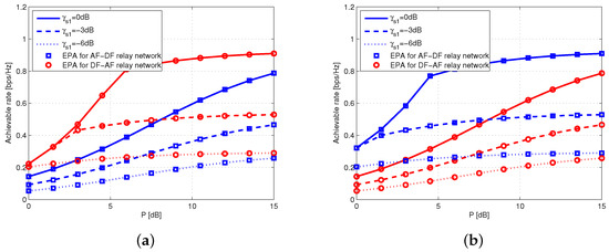
Figure 8.
Achievable rates for the equal power allocation schemes. (a) and ; (b) and .
From Figure 5, Figure 6, Figure 7 and Figure 8, it is noted that the proposed optimal power allocation scheme uses less P than the equal power allocation scheme to keep same achievable rate. Also, the results consider achievable rate per unit bandwidth. Therefore, the advantage of proposed schemes increases linearly according to the bandwidth of systems. Since the bandwidth of recent communication systems has been increased continuously to accommodate future data traffic, the proposed optimal allocation scheme can contribute to increase the power efficiency of the recent wideband systems.
The simulation results in Figure 7 and Figure 8 show that the appropriate hybrid relaying according to the channel condition provides a significant performance improvement compared with other power allocation schemes. For further comparisons, the power allocation schemes in [24,25] are referenced. Since the system model for each paper is different, we refer to the simulation results of each paper. In [24], the proposed power allocation is used to improve a diversity gain by cooperative transmission in the hybrid DF cooperative communication system. Simulation results for the achievable rates according to power usage show an around 3 dB performance improvement compared with equal power allocation. Also, in [25], the proposed power allocation is used to improve a diversity gain by cooperative transmission with relay selection in the multiple relay system. Simulation results for the achievable rates according to power usage show a performance improvement of less than 1 dB. In addition, as the cooperative communication has complicate structure, the problems of sophisticated schedulers and additional overhead occur. However, from the simulation results of Figure 7 and Figure 8, according to channel condition, we confirm an performance improvement of over 5 dB in the range of 5∼10 dB of used power by using appropriate hybrid relaying, as compared with other types of hybrid relaying. Therefore, the analysis of hybrid relaying and power allocation according to the channel condition yields meaningful results.
5. Conclusions
Under a sum relay power constraint, this paper proposed the optimal power allocation schemes to maximize the achievable rates for hybrid three-hop relay networks when the channel gains and the transmit power from the source are given. By solving the optimization problem, we derived the transmit power value from the first relay in closed form for the AF-DF and DF-AF relay networks. With the same channel gains for the AF-DF relay network, we showed that more power should be allocated at the first relay than at the second relay to maximize the achievable rate. In addition, we derived the optimal power allocation scheme for the DF-AF relay network for the possible four cases. When the SNR of the first hop is the same, it is shown that the optimal power allocation scheme for the AF-DF relay network provides a higher achievable rate than for the DF-AF relay network when the channel gain between two relays is higher than that between the second relay and the destination. In contrast, the achievable rate of DF-AF relay network is greater than that of the AF-DF relay network when the channel gain between the second relay and destination is higher than that between two relays. Therefore, we can consider this an appropriate hybrid relaying scheme with optimal power allocation which enables us to provide the best performance in given channel conditions. Both the analytical solutions and simulation results show that the proposed optimal power allocation schemes outperform the grid search schemes and equal power allocation scheme. In addition, the complexity for determining the transmit power value from the first relay in the proposed schemes is much lower than in the grid search schemes.
Author Contributions
Junpyo Jeon and Yeonggyu Shim conceived and designed the experiments; Junpyo Jeon performed the experiments; Junpyo Jeon and Yeonggyu Shim analyzed the data; Junpyo Jeon wrote the paper; Hyuncheol Park has approved the submitted version.
Acknowledgments
This research did not receive any specific grants from funding agencies in the public, commercial, or not-for-profit sectors.
Author Contributions
Junpyo Jeon and Yeonggyu Shim conceived and designed the experiments; Junpyo Jeon performed the experiments; Junpyo Jeon and Yeonggyu Shim analyzed the data; Junpyo Jeon wrote the paper; Hyuncheol Park has approved the submitted version.
Conflicts of Interest
The authors declare no conflict of interest.
Abbreviations
The following abbreviations are used in this manuscript:
| AF | amplify-and-forward |
| DF | decode-and-forward |
| SNR | signal-to-noise ratio |
| SER | symbol error rate |
| BER | bit error rate |
| SEP | symbol error probability |
| CSI | channel state information |
| AWGN | additive white Gaussian noise |
References
- Laneman, J.N.; Wornell, G.W. Distributed space-time coded protocols for exploiting cooperative diversity in wireless networks. IEEE Trans. Inf. Theory 2003, 49, 2415–2525. [Google Scholar] [CrossRef]
- Bletsas, A.; Shin, H.; Win, M.Z. Cooperative communications with outage-optimal opportunistic relaying. IEEE Trans. Wirel. Commun. 2007, 6, 3450–3460. [Google Scholar] [CrossRef]
- Ikhlef, A.; Michalopoulos, D.S.; Schober, R. Max-max relay selection for relays with buffers. IEEE Trans. Wirel. Commun. 2012, 11, 1124–1135. [Google Scholar] [CrossRef]
- Zlatanov, N.; Schober, R.; Popovski, P. Buffer-aided relaying with adaptive link selection. IEEE J. Sel. Areas Commun. 2013, 31, 1530–1542. [Google Scholar] [CrossRef]
- Zlatanov, N.; Ikhlef, A.; Islam, T.; Schober, R. Buffer-aided cooperative commnications: Opportunities and challenges. IEEE Commun. Mag. 2014, 52, 146–153. [Google Scholar] [CrossRef]
- Shim, Y.; Park, H. A closed-form expression of optimal time for two-way relay using DF MABC protocol. IEEE Commun. Lett. 2014, 18, 721–724. [Google Scholar] [CrossRef]
- Liu, T.; Song, L.; Li, Y.; Huo, Q.; Jiao, B. Performance analysis of hybrid relay selection in cooperative wireless systems. IEEE Trans. Commun. 2012, 60, 779–788. [Google Scholar] [CrossRef]
- Liu, X.; Du, W. BER-based comparison between AF and DF in three-terminal relay cooperative communication with BPSK modulation. In Proceedings of the Mobile Ad-Hoc and Sensor Networks (MSN), Hefei, China, 16–18 December 2016. [Google Scholar]
- Shukla, A.K.; Yadav, S. Performance analysis of incremental hybrid decode-amplify-forward cooperative relaying with opportunistic relay selection under Rayleigh fading channels. In Proceedings of the International Conference on Wireless Communications, Signal Processing and Networking (WiSPNET), Chennai, India, 22–24 March 2017. [Google Scholar]
- Wang, C.; Chen, H.; Yin, Q.; Feng, A.; Molisch, A.F. Multi-user two-way relay networks with distributed beamforming. IEEE Trans. Wirel. Commun. 2011, 10, 3460–3471. [Google Scholar] [CrossRef]
- Khattabi, Y.M.; Matalgah, M.M. Performance analysis of multiple-relay AF cooperative systems over rayleigh time-selective fading channels with imperfect channel estimation. IEEE Trans. Veh. Tech. 2016, 65, 427–434. [Google Scholar] [CrossRef]
- Can, B.; Yomo, H.; Carvalho, E.D. Hybrid forwarding scheme for cooperative relaying in OFDM based networks. In Proceedings of the IEEE International Conference on Communications (ICC), Istanbul, Turkey, 11–15 June 2006. [Google Scholar]
- Duong, T.Q.; Zepernick, H.J. Hybrid decode-amplify-forward cooperative communications with multiple relays. In Proceedings of the IEEE Wireless Communications & Networking Conference (WCNC), Budapest, Hungary, 5–8 April 2009. [Google Scholar]
- Hammerström, I.; Wittneben, A. On the optimal power allocation for nonregenerative OFDM relay links. In Proceedings of the IEEE International Conference on Communications (ICC), Istanbul, Turkey, 11–15 June 2006. [Google Scholar]
- Wang, Y.; Qu, X.; Wu, T.; Liu, B. Power allocation and subcarrier pairing algorithm for regenerative OFDM relay system. In Proceedings of the IEEE 65th Vehicular Technology Conference (VTC), Dublin, Ireland, 22–25 April 2007. [Google Scholar]
- Hasna, M.O.; Alouini, M.S. Optimal power allocation for relayed transmissions over Rayleigh-fading channels. IEEE Trans. Wirel. Commun. 2004, 3, 1999–2004. [Google Scholar] [CrossRef]
- Su, W.; Sadek, A.; Liu, K. SER performance analysis and optimum power allocation for decode-and-forward cooperation protocol in wireless networks. In Proceedings of the IEEE Wireless Communications & Networking Conference (WCNC), New Orleans, LA, USA, 13–17 March 2005. [Google Scholar]
- Farhadi, G.; Beaulieu, N.C. Power-optimized amplify-and-forward multi-hop relaying systems. IEEE Trans. Wirel. Commun. 2009, 8, 4634–4643. [Google Scholar] [CrossRef]
- Beaulieu, N.C.; Farhadi, G.; Chen, Y. A precise approximation for performance evaluation of amplify-and-forward multihop relaying systems. IEEE Trans. Wirel. Commun. 2011, 10, 3985–3989. [Google Scholar] [CrossRef]
- Babaee, R.; Beaulieu, N.C. Joint routing and power allocation optimization for multi-hop wireless networks. In Proceedings of the IEEE Wireless Communications & Networking Conference (WCNC), Sydney, NSW, Australia, 18–21 April 2010. [Google Scholar]
- Fareed, M.M.; Uysal, M. BER-optimized power allocation for fading relay channels. IEEE Trans. Commun. 2008, 7, 2350–2359. [Google Scholar] [CrossRef]
- Isikman, A.O.; Yuksel, M. Transmission strategies and resource allocation for fading broadcast relay channels. AEU Int. J. Elecetron. Commun. 2015, 69, 699–707. [Google Scholar] [CrossRef]
- Shen, H.; Li, Z. A distributed three-hop routing to increase the capacity of hybrid wireless networks. IEEE Trans. Mob. Comput. 2015, 14, 1975–1991. [Google Scholar] [CrossRef]
- Xiao, H.; Ouyang, S. Power allocation for a hybrid decode-amplify-forward cooperative communication system with two source-destination pairs under outage probability constraint. IEEE Syst. J. 2015, 9, 797–804. [Google Scholar] [CrossRef]
- Chen, D.; Ji, H.; Li, X.; Zhao, K. A novel multi-relay selection and power allocation optimization scheme in cooperative networks. In Proceedings of the IEEE Wireless Communications & Networking Conference (WCNC), Sydney, NSW, Australia, 18–21 April 2010. [Google Scholar]
- Juhi, G.; Priyanka, M.; Kapil, G. A review on cooperative communication protocols in wireless world. Int. J. Wirel. Mob. Netw. 2013, 5, 107–126. [Google Scholar]
- Huang, G.; Wang, Y.; Coon, J. Performance of multihop decode-and-forward and amplify-and-forward relay networks with channel estimation. In Proceedings of the IEEE Pacific Rim Conference on Communications, Computers and Signal Processing (PacRim), Victoria, BC, Canada, 23–26 August 2011. [Google Scholar]
- Rong, Y.; Khandaker, M.A.; Xiang, Y. Channel estimation of dual-hop MIMO relay system via parallel factor analysis. IEEE Trans. Wirel. Commun. 2012, 11, 2224–2233. [Google Scholar] [CrossRef]
- Laneman, J.N.; Tse, D.N.C.; Wornell, G.W. Cooperative diversity in wireless networks: Efficient protocols and outage behavior. IEEE Trans. Inf. Theory 2004, 50, 3062–3080. [Google Scholar] [CrossRef]
- Shannon, C.E. A mathematical theory of communication. Bell Syst. Tech. J. 1948, 27, 379–423. [Google Scholar] [CrossRef]
© 2018 by the authors. Licensee MDPI, Basel, Switzerland. This article is an open access article distributed under the terms and conditions of the Creative Commons Attribution (CC BY) license (http://creativecommons.org/licenses/by/4.0/).