The Dynamic Routing Protocol Implementation Strategy of the Cooperative Control Awareness Combat Network


1
School of Astronautics and Aeronautics, University of Electronic Science and Technology of China, Chengdu 611731, China
2
Beijing Institute of Special Vehicles, Beijing 100072, China
3
School of Control Engineering, Chengdu University of Information Technology, Chengdu 610225, China
4
Beijing Hui Tian Wei Technology Co. LTD, Beijing 100085, China
*
Author to whom correspondence should be addressed.
†
Cheng-Hai Wu, male, doctoral student in control science and engineering, senior engineer, mainly researching communications, multi-agent cooperative control, and equipment support.
Appl. Sci. 2018, 8(6), 948; https://doi.org/10.3390/app8060948
Submission received: 23 April 2018
/
Revised: 1 June 2018
/
Accepted: 6 June 2018
/
Published: 7 June 2018
Abstract
:In view of the problem of dynamically setting up a fire aiming data chain between the sensors and the shooters in the same battle echelon in the awareness combat network (ACNET) of the future unmanned collaborative combat system, based on the wireless mobile Ad-hoc network technology, a closed loop routing control model is built, in which the information transmitted in the ACNET is regarded as a continuous fluid according to the requirement of the transmission packet and its link state. Based on this model, a high-speed mobile dynamic real-time routing protocol (HDRRP) and its implementation method are proposed. The routing strategy combines the cellular network and Ad hoc to design a node state routing and mobile cellular routing mode and algorithm, and automatically selects the corresponding routing algorithm according to priority. Thus, the sensing information and the combat target strike are organically integrated, and the data are delivered at high speed and in a real-time, dynamic, and reliable way. The simulation results show that this protocol can greatly improve the packet delivery rate, and compared with the traditional wireless mobile Ad-hoc network, it can shorten the transmission delay, has a better anti interruption performance, and reduces control overhead, route discovery time, and routing maintenance time.

1. Introduction
The modern information-based combat system is becoming more and more complex; its structure covers multi-dimensional and multi-faceted elements on the battlefield, which run through all aspects of the combat process and can carry out autonomous battle cooperative control based on the information network. This kind of cooperative control is an autonomous coordination for the whole process of combat, which can transversely integrate various combat elements into a combat system through the information network and share the battlefield situation under the support of the information network in the process of the deployment of forces, the planning of operations, and other aspects. However, current communication networks, sensing networks, and combat weapon systems are all designed and used based on the traditional combat model, thus having the problem that they lack autonomous cooperative control among them. Based on the future unmanned combat system, all operational elements are used to achieve a seamless link between each other through autonomous cooperative control, thus achieving autonomous coordination. In the process of cooperative control, the battlefield situation is changing rapidly, so the advanced combat communication system must be able to accurately and completely grasp the battlefield situation [1], perceive the battlefield, and integrate all information into an information network so as to obtain high-precision and overall dynamic combat situation information [2,3] and carry out effective coordination. In the combat system, it is necessary to dynamically establish a fire aiming data link between the sensor and the shooter within the same battle echelon, and organically integrate the information perception and combat strikes so as to strike the target accurately. Because of the intelligence of various entities in an information-based combat, they can share the battlefield situation and become intelligent entities, leading to the formation of self-organizing cooperative behavior on the information-based battlefield. In the study of this kind of autonomous cooperative method and technology, the information between various combat elements and functional units is effectively integrated so that interconnection and interoperability can be realized among each other.
Based on the combat network’s requirement of self-organizing [4,5] cooperative control tasks and capabilities, this paper proposes the concept of the “awareness combat network”, which integrates information perception and combat strikes organically. An awareness combat network is a very complex network. One of the key technologies is employed to establish a high-speed real-time dynamic routing protocol for the awareness combat network with dynamic network typology which is suitable for cooperative control requirements.
2. Network Model and Problem Description
With the continuous improvement of maneuverability, shooting distance, precision strike, and other combat capabilities of the main battle weaponry, in order to improve the viability and strike capability of weapons, it is necessary to comprehensively integrate functions such as communication, navigation, positioning, and recognition, organically combine information perception and combat strike, achieve real-time converged data transmission of the “Awareness Combat Network (ACNET)” under the condition of high-speed movement, and correspondingly construct a dynamic routing protocol mechanism for the awareness combat network based on cooperative control. In this paper, wireless network technology is used to achieve cooperative control of combat, thus ensuring that the target perception information to the shooter and other information in the process be transmitted in nearly real-time.
2.1. Closed-Loop Control Model of an Awareness Combat Network
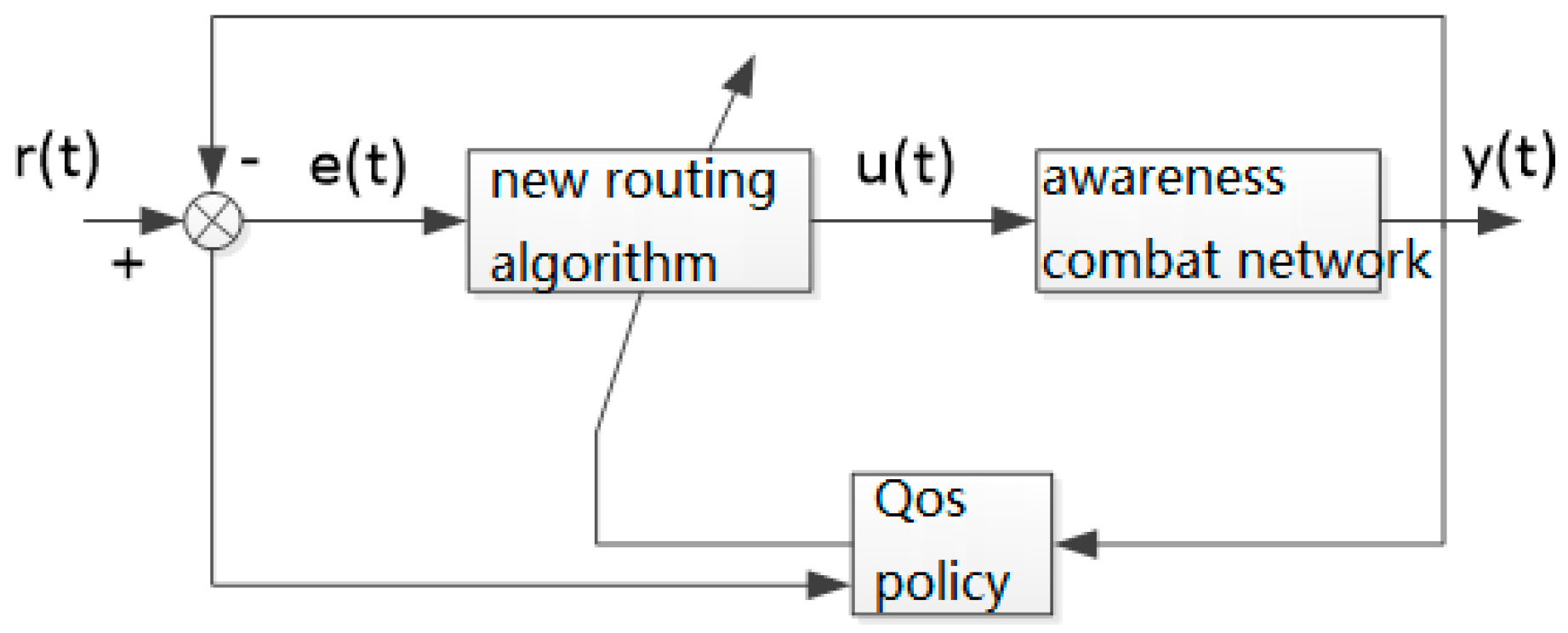
In a specific geographical area, nodes perform closed-loop topology control, discovering and maintaining the routing according to the needs of the transmitted data packet and its link state. The information transmitted in the awareness combat network is regarded as a continuous fluid, the principle of the routing algorithm is studied by using the control theory, and a closed-loop routing control model is formed, as shown in Figure 1.
In Figure 1, represents the existing routing, represents the routing discovered and maintained by the awareness combat network using the routing algorithm designed in this paper, represents the routing error, and represents the result of the routing algorithm, and they are all used for controlling the awareness combat network. The nodes in the network use the routing algorithm designed in this paper to calculate the transmission power required by the node according to the routing error so as to control the topological structure of the awareness combat network within a specific range. The routing under this topological structure is negatively fed back to the input of the routing algorithm and the routing algorithm is adjusted online accordingly according to the QoS policy, finally forming a closed-loop control structure.
This is a conceptual model, including perception by combat network dynamic, real-time routing changes, so there must be an adjustment strategy, but adjustment is gradual, as reflected by the effect of the routing computation load.
2.2. Awareness Combat Network Topology
Based on the closed-loop control model of the awareness combat network and its analysis, in this paper, the topological structure of the awareness combat network is designed as a planar peer-to-peer self-organizing structure, as shown in Figure 2.
Each node in the awareness combat network can communicate with other neighboring nodes and is not limited by its subordinate relationship and command level. The composition and topology of the whole network are shown in Figure 2, in which the purple dotted line represents a multi-hop forwarding wireless link, and the orange or green solid broken line represents a wireless link within a “perceived cell”. The geographical range of the perceived cell is controlled automatically by the transmission power based on the strength of the wireless signal. In the perceived cell, the forwarding source node of the service data packet is referred to as a “perceiving base source”, for example, the node “Z9”, while the receiving node of the service data packet is called the “perceiving mobile terminal” of the “perceiving base source”. Considering the fact that the perceived cells may have three or more overlapping distributions in the same region, the nodes may move between different perceived cells. When the signal strength is weakened or interfered with to a certain extent, hard handover is used to switch the nodes to a perceived cell with the best signal for communication. In order to increase the connection speed for frequent handovers, a dedicated call channel is reserved for the purpose of the communication control of the perceiving base source over its perceiving mobile terminals [2]. When a node switches from one perceived cell to another, its communication frequency must be accordingly changed immediately. Such a cross-cell handover sometimes occurs intensively in time distribution; therefore, the node radio is required to be designed as a software radio mode, and it needs to have a flexible frequency detection function at the same time. Each node adopts distributed control. A certain node only retains the information of its neighbor nodes and valid links [6].
2.3. Analysis of Current Advanced Network Routing Protocols
Currently, advanced network routing protocols mainly include DSDV (Destination-Sequenced Distance-Vector Routing) [1], AODV (Ad-hoc On-demand Distance Vector), LAR (Location Aided Routing), STG (Space-Time Graph) routing framework, CBMANET (Control-Based Mobile Ad-hoc Network) [2], and the command and control information network-tactical system WIN-T [3,4]. The DSDV protocol has a poor convergence performance when the network topology changes frequently [5]. Nodes must periodically broadcast updated information no matter how variable the network traffic is and whether or not they need to send data. As the number of nodes in the network increases, the capacity, overhead, and bandwidth of the routing table also increase accordingly. The DSDV protocol requires that each node be saved to the routing of all nodes in the network; in this way, the redundant routing entries can cause a waste of resources. The AODV protocol is an improved on-demand routing protocol based on the DSDV protocol; this protocol has a strong real-time performance but weak anti-interruption capability. The LAR protocol is a geo-location assisted routing protocol. It is also an on-demand routing protocol based on the source routing [6]: the node obtains its own current location (x,y) through GPS, the source node adds the current time and location to the sending route request, the destination node adds its current time and location in the route reply, and the node that forwards the request or responds to the packet can obtain the location information of the source node or destination node. The DTN (Disruption Tolerant Network) constructs the space-time diagram from the space-time routing table, converts the time-dependent network into classical static network problems, and then uses the shortest path algorithm to solve the path between node pairs [7]. This protocol has a strong capability to resist network interruption, but it has a low data transmission rate and low real-time performance. The CBMANET protocol self-perceives and chooses the optimal frequency and path during maneuvering, and can also store information in temporary network nodes until the connection recovers, so there is no need to worry about signal interruption and delay; however, it has the disadvantage of a low transmission rate [8]. The command information network tactical system WIN-T routing protocol provides unprecedented network throughput and control (fast-stop communication and Satcom-on-the-move) through a comprehensive approach and provides a joint system for managing and controlling WIN-T node services [9,10]. To sum up, the parameter selection of the general AODV network is not suitable for awareness combat networks, and may even lead to a significant decline in network performance; DTN networks are helpful for the stable operation of awareness combat networks. However, if the network is established completely according to the DTN strategy [11,12], it is difficult to guarantee the real-time transmission of data. The integrated combat network provides technical support for future unmanned military operations, but it cannot effectively meet the requirements of real-time data transmission under high-speed mobile conditions. Therefore, this paper is of great application value for researching the routing protocol and its implementation method for awareness combat networks.
3. Implementation Strategy of Dynamic Routing Protocol for Awareness Combat Networks
There are two routing mechanism modes for awareness combat networks: node state routing and mobile cellular routing. The switching of the two routing mechanisms is controlled by the transmission power of the node. For each node, power switching is performed only when it cannot find the next-hop node according to the current routing mechanism, thereby avoiding the end-to-end delay [13] caused by frequent power switching. In general, when the transceiver parameters and the channel conditions are fixed, the transmission power of the node determines the communication distance of the node. The transmission power parameter of a node is contained in its data packet transmitted, and the node receiving the data packet sets the transmission power parameter to be the same when replying to the above node. In this way, unidirectional links can be avoided. The routing protocol designed in this paper supports QoS and automatically selects the corresponding routing algorithm based on the priority according to the service type transmitted by the node (i.e., the packet header identifier added on the network layer).
3.1. Node Status Routing
3.1.1. The “Flat” State of the Awareness Combat Network Routing
(1) Construction of AODV-DTN protocol and its algorithm
When there is no real-time information to be transmitted, the awareness combat network maintains connectivity as much as possible, shares the situation information between nodes (periodically transmits information such as the location and working state to adjacent nodes), and uses a small transmission power. The running state of the network at this time is referred to as the “flat” state; the state of the awareness combat network when transmitting real-time information is called the “peak” state. The operational environment of the awareness combat network determines that its “flat” state is consistent with the DTN network model, and the network protocol can still work without crashing under the condition of frequent connection and disconnection between moving nodes [11]. The core idea of the “flat” state routing algorithm is to adopt the method of storing firstly and then looking for an opportunity to forward data packets, overcoming the limitations of traditional routing methods due to limited node caching and the absence of continuously available end-to-end routing, thus realizing the maximum possible transmission of information.
The “flat” state of the awareness combat network is the basis of the “peak” state. It enables each node in the network to obtain time-varying information of neighboring nodes and provides information support for the efficient selection of “peak” state nodes.
The “flat” state routing algorithm, which is based on the AODV protocol, implements the DTN overlay, the DTN message mechanism, the DTN route discovery mechanism, and the store-and-forward mechanism, i.e., the AODV-DTN protocol.
The algorithm is as follows:
- (1)
- Adding a DTN overlay immediately to the AODV network layer.
- (2)
- Adding new control messages and response messages to implement the DTN message mechanism.
- (3)
- Implementing the disruption tolerant function in the DTN overlay. When the link is disconnected, no connection repair is required and data packets continue to be transmitted.
- (4)
- When the routing link selected by AODV is about to break, try to find out a route that can replace the broken route. If there is no available route, the delay is tolerated and it waits for another opportunity; once there is an “opportunity link” available, the data packet will continue to be transmitted. An “opportunity link” is a link that is currently temporarily unavailable but may become available as the nodes move or channel interference factors disappear.
- (5)
- After the routing link is interrupted, the node stores the data packet, namely, the packet is encapsulated into a DTN packet and stored in the storage area of the DTN overlay instead of sending a large number of route control broadcast messages. The DTN packet format is shown in Figure 3.
The DTN packet is passed in the DTN overlay, as shown in Figure 4, from the previous-hop DTN storage area to the next-hop DTN storage area. When the previous-hop node sends a DTN packet, if no response is received from the next-hop node within a certain time range, the previous-hop node sends the DTN packet again from its own DTN storage area. If a response is received from the next-hop node within a certain time range, the previous-hop node deletes the DTN packet from its own DTN storage area. After the link interruption area is skipped, the DTN packet removes the control message restored to the original data packet and will then be passed on to the destination node.
(2) The AODV-DTN flood routing discovers, which uses geo-location information
Each node of the awareness combat network has a high-precision positioning function and the function of real-time perception of its own state. The routing protocol of the awareness combat network should make full use of these capabilities [12]. The awareness combat network mainly transmits the target aiming information, and the position information of each node is indispensable. The nodes involved in the routing have a certain locality in the geographical probability distribution, most of which are consistent with the direction of the connection between the source node and the destination node and are located nearby. The AODV-DTN flooding based on geographic location information initiates route discovery, and the location information is used to limit the scope of flooding. With the support of the location information, the node carries out a route discovery process, saves the DTN routing table, and reserves the basic information of the route for the “peak” state of the node. The AODV-DTN flooding using geographic location information as shown in Figure 5.
The polar coordinate system M is established by taking node P1 as the pole and the direction from P1 to T as the pole axis. The node P2 is at [0°, 90°], node P4 is at (90°~270°), and node P3 is at (270°~360°). If the route extends backward, the flooding range is neighboring nodes within (90°~270°); node P4 is the flooding object and is used as an alternative next hop. In the process of routing, the current node is taken as the pole and the direction from the current node to the previous node is taken as the polar axis to establish a polar coordinate system, the flooding range of which is the same as the above range. If the included angle between the direction from the flooding object to the current node and the polar axis of the polar coordinate system M is an acute angle or a right angle, the flooding object is used as an alternative next hop.
The faster the node moves, the more frequently the Hello messages are sent, and the faster the routing is updated. Nodes send Hello messages to maintain the stability of the network topology.
The flooding cycle is determined by the speed and angle of the node movement. The minimum value of the impact of distance and angle changes on the network routing is used as the update cycle. Assuming that the moving speed of the node is V m/s and the coverage is R m, the flooding will be initiated if the relative angle between nodes changes by more than . The time taken for the angle change to reach is greater than , so the minimum time is used as the update cycle T.
In order to reduce the number of redundant DTN packets in the network, the intermediate node also records the processed DTN packet ID number, and the DTN packet with the same ID number is processed only once according to the above procedure.
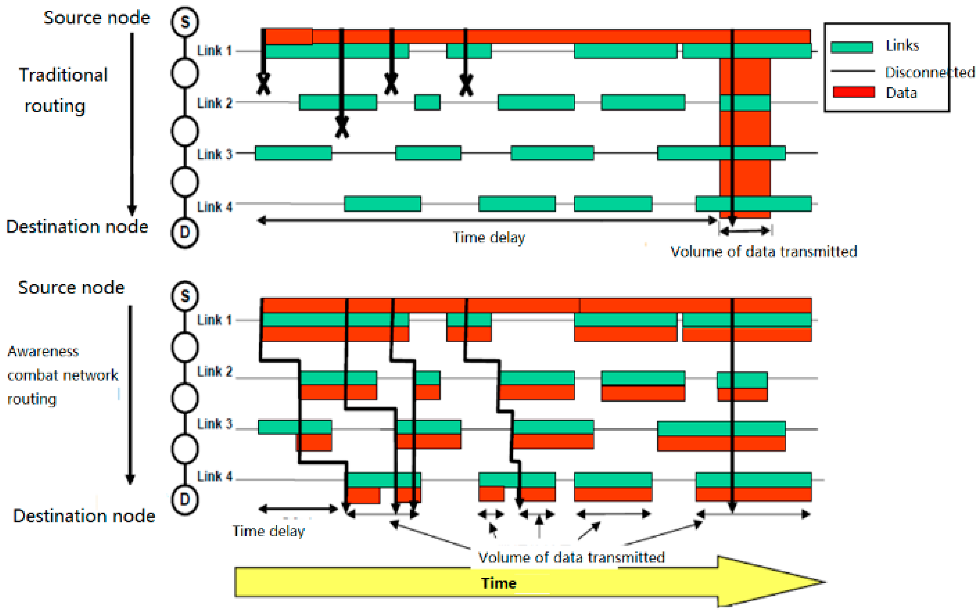
Compared with the traditional routing mechanism, this routing mechanism shortens the time delay and increases the probability of successful data transmission. As shown in Figure 6, when the green line segments (representing the link connection time) are the same, the red line segments in the lower half (representing the amount of data transmitted) are obviously more than those in the upper half, and the starting positions of the red line segments (representing the delay) are also ahead of those in the upper half.
3.1.2. “Peak” State of the Awareness Combat Network
When the nodes of the awareness combat network transmit data packets of voice and target aiming information, they first use a small transmission power to communicate. The state of the nodes at this time is called the “peak” state in this paper. Although the “peak” state of the awareness combat network must also consider the dynamics of the topology, the most important thing is to consider the stability of the link and ensure the real-time transmission of information. Even if the enemy target information without timeliness is passed to the fire control system, it is useless. Therefore, the network model of the “peak” state is no longer consistent with the DTN network model, but the real-time requirements are added on the basis of the DTN network model. Obviously, allowing interruption and ensuring real-time performance is a contradiction. Although this article cannot completely resolve this contradiction, it can try to use a series of technical means to weaken the degree of contradiction.
Under the condition that the data transmission rate is constant, if the link’s stable duration is much higher than the round trip time (RTT) of the data packet, that is to say the change of the network topology is slow relative to the transmission of the data packet, the link can be considered static during a data packet transmission. The speed at which the network topology changes is quantitatively described by the frequency of link disconnections on a path. Let the number of disconnections within time RTT, then”
In the “flat” state of the awareness combat network, the value of is pretty large; while in the “peak” state of the awareness combat network, .
In practical applications, some nodes in the awareness combat network are in the “flat” state, while some nodes are in the “peak” state. The “flat” state guarantees the stable operation of the network. In the case of frequent connections and disconnections between nodes, network routing can converge as quickly as possible. Nodes switch between “flat” and “peak” states depending on the information type of packets they process. If the node processes data packets with strong real-time information such as enemy target information provided for the fire control system and satisfies the minimum stability coefficient, it is in the “peak” state; otherwise it is in the “flat” state. The awareness combat network establishes a target aiming-fire strike data link through “peak” state nodes.
Because of the high-speed movement of the nodes, the network topology changes frequently. This will directly result in unavailability of the selected path and consequently cause a high packet loss rate. Predicting the movement of the vehicle can reduce the impact of network fragmentation. In the process of data transmission, each node used on the path monitors its connectivity to its previous node and the next node and predicts its connection duration to its next node in order to establish a space-time routing table. If the predicted connection time is too short, it will look for another path that can last long enough, and transmit data on the newly established path. If no new path is found nearby, it will send a message to the source node, switch to mobile cellular routing, and let it find a new path in a large range and with less hops.
The stability coefficient represents the degree of stability of the data link between two nodes. It is the product of the time stability coefficient and the signal strength . Set the maximum communication distance between the two nodes in plain areas without an interfering signal as , the real-time distance between two nodes as , and the speed of the current node relative to the previous node (assuming that the direction of the nodes away from each other is positive) as , then:
Packets with real-time information are only transmitted between nodes in the “peak” state, spreading just like sea waves.
The sensor aims and locks the target, and the aiming position and image after aiming are transmitted in real time. The relative position of the sensor platform to the firepower platform is calculated in real time. The above-mentioned aiming position and relative position are added on the fire platform to obtain the aiming position of the fire platform. The image is not processed except for real-time transmission.
Targeting information packets also have the instant speed of the target and its accelerated speed . To obtain the accurate instant speed and accelerated speed of the target, the reconnaissance vehicle has higher requirements on the aiming method and accuracy of the target. Set the target irradiation interval time , record the target position obtained by the two irradiations, the target position obtained by the previous irradiation, and the target position obtained by the current irradiation, then:
During the time when the route is interrupted, the attack vehicle assumes that the target uniformly accelerates and estimates the real-time moving distance between the attack vehicle and the target position considering the last time it received the information. In this calculation, is the duration of the route interruption.
When the route is restored, the target location is relocated with the newly received information.
Similarly, when the intermediate node N of the routing forwards data packets, it also adds its own instant speed and accelerated speed fields. During the route interruption, assuming that the next-hop node (N + 1) accelerates uniformly, the location of the next-hop node (N + 1) is estimated, and then the azimuth and distance between nodes N and (N + 1) are calculated according to the motion of node N. If the azimuth exceeds the broadcast range of node N, the distance exceeds the communication range of node N, or the route interruption time exceeds the maximum allowable time , then node N stops forwarding packets to node (N + 1) and re-looks for the next-hop forwarding node. Through such prediction, the node establishes a local space-time routing table.
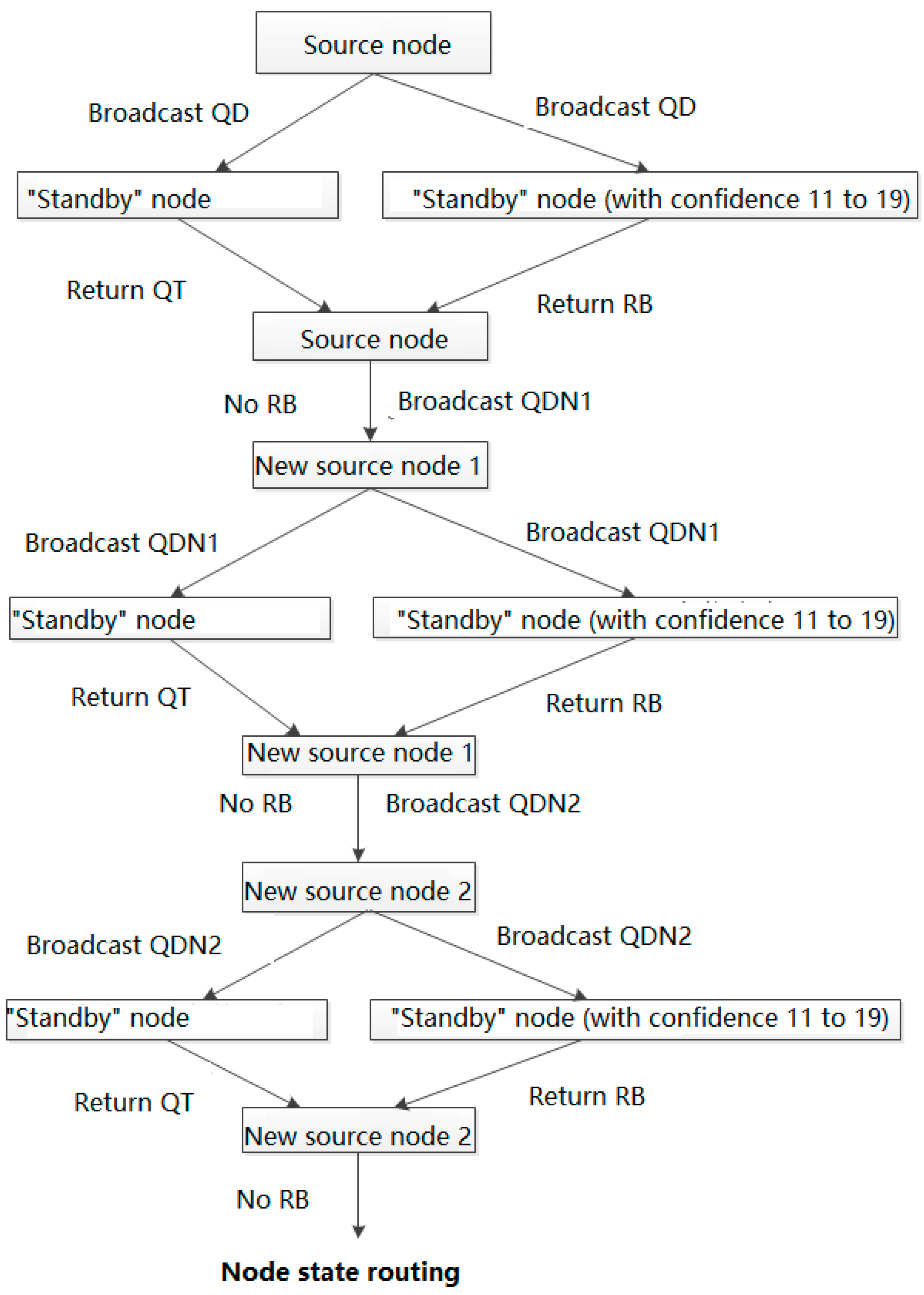
The node state routing algorithm for awareness combat networks is a distributed self-stabilization algorithm that implements rule constraints and information interactions among nodes. It adapts the topological change of each node in the network, maintains routing stability, and reduces routing overhead. The source node that transmits the target aiming information also needs to intelligently select the destination node; it broadcasts messages based on the link layer and carries out one flooding event across the whole network, and the convergence speed is fast. The source node broadcasts a message QD (to look for the destination node); the neighboring node receives the message and inquires its own status across the layers. For the mobile terminal in the “standby” state, if their confidence is within the range of 11 to 19, the message RB (confidence confirmation; the message contains the position coordinates of the node) is returned; in each RB, the source node will select the closet node as the destination node, and if the distance is equal, it will select the node with higher confidence as the destination node. If the source node does not receive any RB message, it switches to mobile cellular routing.
3.1.3. Design and Implementation of Routing Control Selection Module
The design of the routing protocol is composed of five functional modules: initialization and main control module, packet processing and sending module, packet reception processing module, and routing control selection module. Its core is the routing control selection module [14,15].
(1) DTN Initialization and Main Control Module
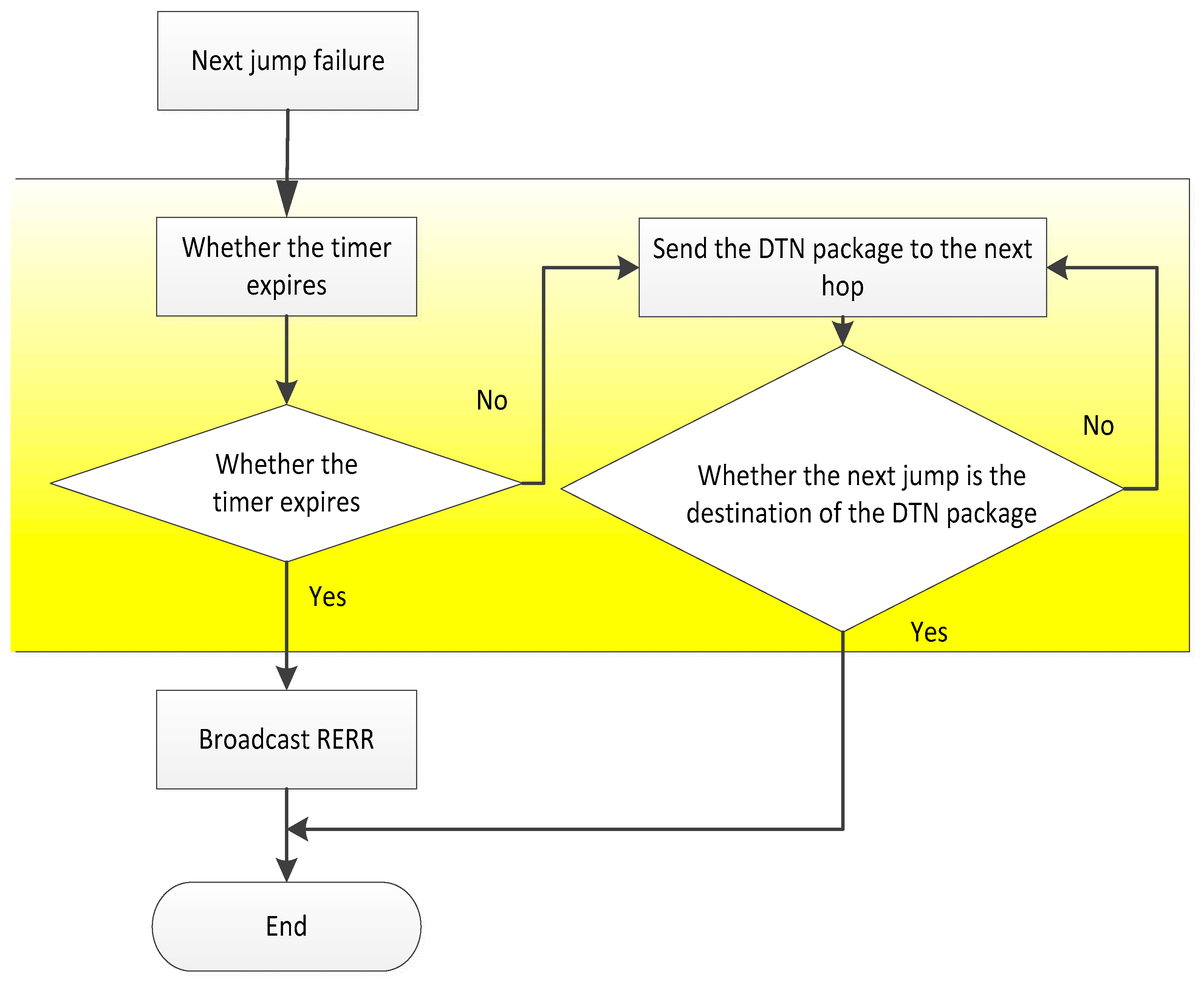
The DTN initialization module is the main control module of the routing mechanism. As long as the node running the AODV protocol receives the link failure message from the node to the next hop node, the DTN initialization module will turn on a timer. If the data packet is successfully passed to the destination node of the DTN before the timer expires, the DTN initialization module sends a “successful” control message to the node running the AODV protocol. If the data packet is not successfully passed to the destination node of the DTN when the timer expires, the DTN initialization module sends a “failure” control message to the node running the AODV protocol. After receiving the message, the node broadcasts the error message RERR to the neighbor node according to the AODV protocol, and runs the routing maintenance or routing of the AODV protocol. In this way, it rediscovers the process, as shown in Figure 7.
(2) DTN packet processing transmission module
The DTN packet processing module first acquires the data packets which have not been sent by the AODV protocol, and adds the DTN Baotou to the DTN package. The DTN package is stored in the storage area of the DTN overlay layer of the node, and then a copy of the DTN packet is generated as the data to be sent. Query the DTN routing table of the node to get the next hop address. The node sends the DTN packets to be sent to the storage area of the DTN coverage layer of the next hop node. After the next hop node receives the DTN package, it returns a reply message (including the ID number of the DTN packet, the last hop address), and if the node does not receive a reply message from the next hop, a new copy of the DTN packet will be generated, and the ID number of the DTN packet is changed to the next hop node, as shown in Figure 8.
(3) DTN packet reception processing module
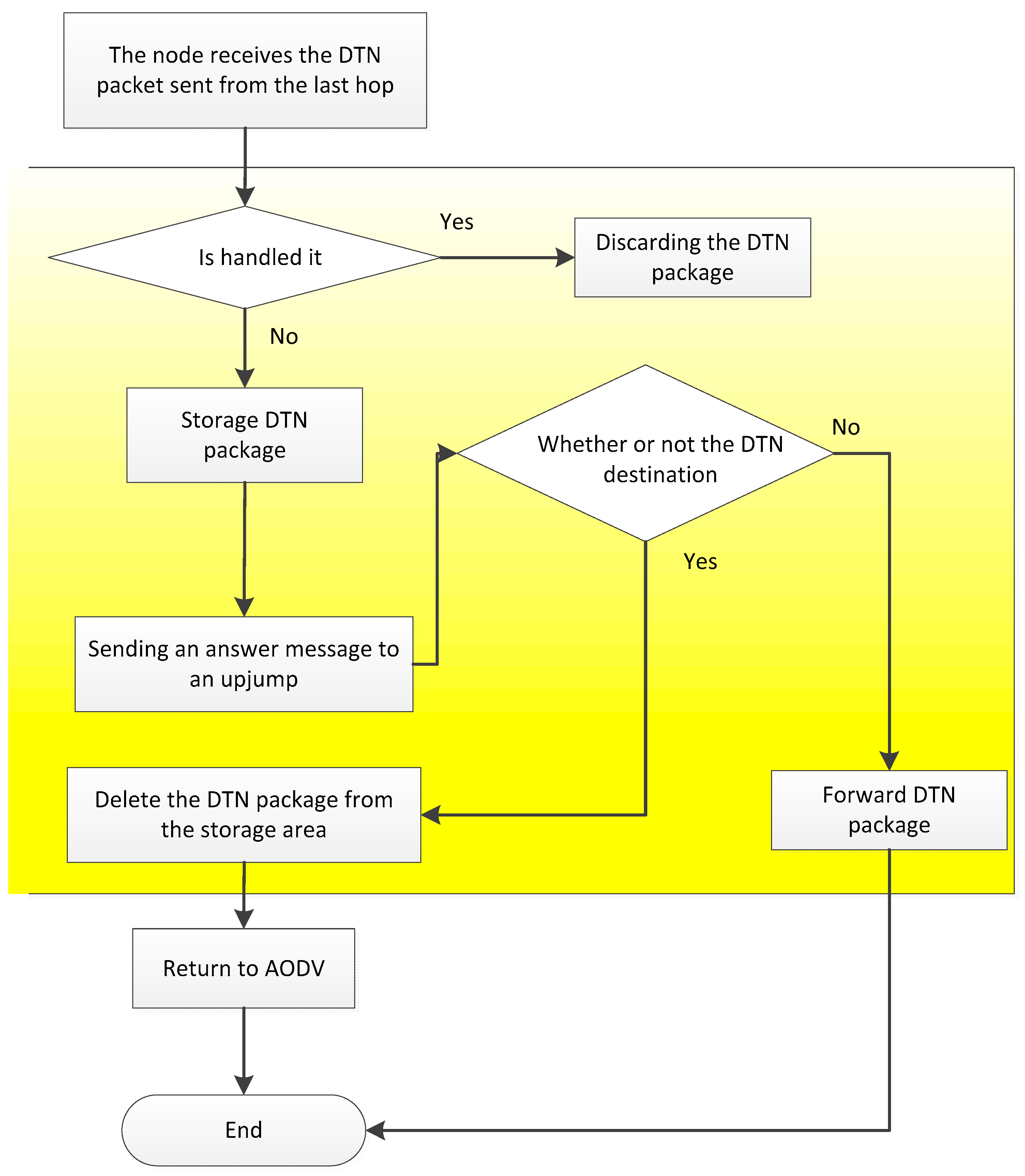
When the DTN packet sent by the last hop node is received, the next hop node determines whether the DTN packet has been processed through the ID number of the DTN package. If the package is processed, it is discarded; if it is not processed, it is put in the storage area and a reply message is sent to the next hop node. If the node is the destination node of the DTN package, the node will remove the DTN Baotou, restore the DTN packet into the original data packet, and continue to run the AODV protocol to handle the packet. The node receives the reply message from the next hop node and removes the DTN packet in the storage area according to the DTN package ID in the reply message, as shown in Figure 9.
(4) DTN routing control selection module
It is important to make full use of AODV’s routing discovery mechanism to build the DTN routing table. The DTN routing table records every route established by route discovery when running AODV protocol, and updates only with time without deleting routing records. When the link is disconnected or the node moves so that the adjacent nodes are no longer adjacent, the relevant routing marks in the DTN routing table are “invalid”. When link recovery or node mobility allows nodes to have new neighbor nodes, the relevant routing marks in the DTN routing table are “valid”.
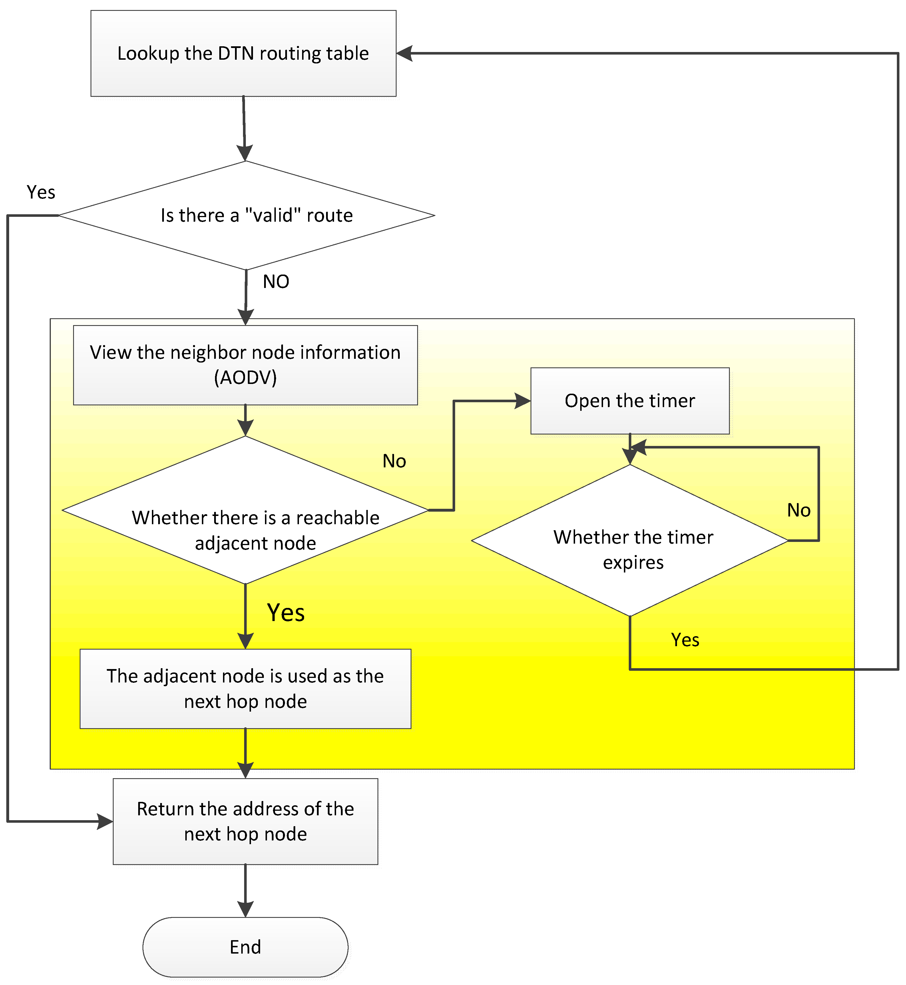
Nodes look for whether the DTN routing table has a marked “valid” route to the destination node. If there is, the address of the next hop node is returned; if not, the DTN route discovery is performed, as shown in Figure 10. The node obtains the adjacent node information by running the AODV protocol to see if there is a reachable neighbor node. If the node returns the address of the neighbor node, the DTN packet is sent to the neighbor node, and then the DTN packet is forwarded by the neighbor node. If there is no reachable neighbor node, the timer is opened, waiting for the valid link to appear until the timer expires, and the DTN routing table is re-searched.
In the process of information transfer, the DTN overlay is added to the AODV protocol, and the packets received (including network management data, node location, and combat status data, etc.) are encapsulated into DTN packets, stored in local nodes, and the DTN packets are carried in the process of node movement, and link connectivity between adjacent nodes is sought as a link between the nodes. When the road is connected, it is forwarded. The routing between nodes in the “Ping” state is distributed only in adjacent nodes, that is, hopping to the hopping route. There is no route between the source end and the destination end at the same time. The “peak” state nodes set up the space-time routing table according to the information obtained in the “flat” state, and forward the packets according to the AODV protocol of the geographic location assisted routing (including the target real-time/near real-time information data for fire control).
3.2. Mobile Cellular Routing
(1) Route discovery
If the node needs to transmit voice and target aiming information, but cannot establish “node state routing” in a low power mode, then it will use a large transmission power with a coverage radius of about 10 km. This node is the “sensing base source” and is equivalent to a “base station” in a cellular network. The node within the coverage of the sensor cell is the “sensing mobile terminal”. If there are no destination nodes in these sensing mobile terminals, then the “sensing base source” broadcasts a message QR to these mobile terminals (to find a route; the IP of the destination node is contained in the packet). After the data transmission is completed, the destination mobile terminal takes over the source node and works as a new “sensing base source”, finds a destination mobile terminal in a new perceived cell, and continues to send data. The new perceived cell can be seen as the maneuver of the original perceived cell. The maximum number of times of maneuvering in the perceived cell is three. After the data reaches the destination node, the sensing base sources used along the way can directly communicate with each other. From the source node to the destination node, there is mostly one hop and can be up to three hops. The process of determining the destination node is shown in Figure 11.
The source node that transmits the target aiming information first has a process of determining the destination node. This process is implemented in the form of a source node broadcast. The source node as a sensing base source broadcasts the message QD (finding the destination node) in its cell. The sensing mobile terminal in the cell receives the message and queries its own state; for the sensing mobile terminals in the “standby” state, if their confidence is within the range of 11–19, the message RB is returned to the sensing base source (confidence confirmation). The sensing base source will select the sensing mobile terminal with the highest confidence as the destination node in each RB; otherwise, it returns the message QT (request for transmission) to the sensing base source. If the sensing base source receives the RB message, the QT message will be ignored; if all of the messages received by the sensing base source are QT messages, the message QDN1 is broadcasted (continuing to find the destination node); mobile nodes in the perceived cell will take over the sensing base source and become new source nodes to broadcast QDN1, performing the process of determining the destination node. If the destination node has not yet been found, the message QDN2 is broadcasted (continuing to find the destination node) and the process of determining the destination node is performed again. If the destination node is still not found, it will be switched to node state routing by the original source node.
(2) Route maintenance
The source node and the destination node establish a route through the intermediate sensing base source. The information of these perceived cells (including the location range of the cell and the location and state of the sensing mobile terminal covered by the cell) is recorded by the source node and the destination node. If the communication between the sensing base sources is disrupted due to a change of the network topology and the route becomes unavailable, then the source node and the destination node will simultaneously search in these recorded cells to find the sensing mobile terminal (that can establish communication) as a new sensing base source so as to restore the routing. If a new sensing base source cannot be found after searching, node state routing is performed.
3.3. Link Delay Model of the Awareness Combat Network
Real-time capacity is one of the most concerning aspects of the awareness combat network. Therefore, it is necessary to study the time delay problem of links in the awareness combat network. In a traditional network routing protocol, time delay can be expressed by the equivalent number of hops; in the awareness combat network, time delay is a comprehensive parameter. It directly reflects the residence time of data packets in the network and also indirectly reflects the topology connectivity, congestion, and other conditions of the network. In this paper, a link delay model is established by considering the source of delay in the awareness combat network.
The data packet on the link first waits for the link to be connected; the waiting time is denoted as . After the link is connected, it starts to send data packets. According to the first-in-first-out (FIFO) queuing principle, it is necessary to wait for the first-in packets to be sent; this queuing time is denoted as . Finally, the transmission time of the packet itself is denoted as . Among them, is the new time delay introduced by links in the awareness combat network. In the “flat” state of the awareness combat network, the burden for the link is relatively light and the amount of data transmitted is not large, so and are small and even negligible, but is a main component. In the “peak” state of the awareness combat network, the link is heavily burdened and the amount of data transmitted is large, so the data packet may need n times to be completely transmitted rather than just one time during the period when the link is connected. The data packet undergoes a queuing delay and link establishment delay. The total time delay is as follows:
4. Numerical Simulation and Result Analysis
In order to verify the effectiveness of the proposed high-speed mobile real-time dynamic routing protocol and its implementation, the following numerical simulation is designed in this paper.
4.1. Setting Up a Numerical Simulation System
The awareness combat network simulation system should have the following functions: simulation scenario establishment, simulation process control and management, network topology, information generation simulation, network interconnection, routing maintenance, data forwarding, node movement, parameter setting, and statistical analysis.
The awareness combat network simulation system refers to the Opportunistic Network Environment (abbreviated as ONE) [16,17], a DTN special network simulation tool developed by the Nokia Research Center of Helsinki University of Technology in Finland. It is developed with the JAVA programming language and adopts the agent-based discrete event simulation mechanism, which mainly includes the modeling of node movement, node communication, node routing, and message processing between nodes, viewing node movements and message transmissions in real time via the GUI, and collecting and analyzing visual data results. In this paper, the wireless link is abstracted into a communication range and bit rate. The parameters are pre-configured with multiple options before simulation, and the parameters are then selected accordingly during simulation according to the data transmission conditions.
In this paper, the AODV protocol is implemented with Java programming language, and then the AODV.java class is rewritten, the message-related events and resource management callback functions of the MessageRouter module in ONE are called, the location of the node and the current time values are read, the space-time routing table is established, the message events are processed according to the DTN routing mechanism, and method functions in the ActiveRouter class (handling message transmission between neighboring nodes, successful transmission/interrupted transmission, etc.) are extended. In this way, an ActiveRouter subclass DTN-AODV.java of the DTN overlay is added to the AODV protocol. DTN-AODV.java is placed in the routing package and compiled together with other routing models. When the program is run, the awareness combat network routing protocol designed in this paper can be implemented.
4.2. Numerical Simulation Scenario Design
In the process of network simulation experiment, the mobility model is one of the necessary simulation parameters. It is used to describe the movement mode of the mobile node, including movement characteristics such as position, speed, direction, and accelerated speed of the mobile node. In the awareness combat network, due to the movement of the nodes, their positions are constantly changing, and the distance between the nodes is also dynamically changed, thus causing a dynamic change in the network topology [18]. The performance indicators of the network protocol, such as transmission delay, network throughput, and routing effectiveness, are closely related to the locations of various nodes in the network and are affected by the node mobility model [19]. Different mobility models have different effects on network performance [20]. In order to achieve the best network design performance, network protocols must be studied under the corresponding mobility model. Therefore, the mobility model is a basic problem of mobility research and is also the key modeling technology in the process of protocol research [21].
At the micro level, the research of the mobility model mainly includes the node location, node speed, and its correlation with other nodes. These factors determine the connection establishment and disconnection of links between nodes, which directly affect the topology of the network and consequently affect the performance of the protocol. In a sensor network, most of the nodes are in a stationary state, and the nodes can be placed in a specified location as required. In a civil Ad-hoc network, most of the nodes are independent of each other, and the movement of the nodes is strongly random. In most studies, a random way-point mobility model is used. In a tactical Ad-hoc network, nodes cooperate with each other, move in a group, and adopt a reference point group mobility model. However, in an awareness combat network, the mobile mode of the node is particularly complex; it has the characteristic of a variety of mobility modes and there is not only one mobility model [22].
The mobility model of a node in the actual battlefield environment is very complex. Command actions among aircrafts, armored vehicles, and infantry corps, and the movement between these groups, generally have their own reference point paths. In hierarchical mobility models, for example, helicopters and infantry regiments, the characteristics of the nodes in these two groups are completely different. No matter which mobility model is selected, it can only describe the characteristics of the selected models, and cannot represent the mobility characteristics of other mobility nodes. It is obviously inappropriate to only use the conventional reference point group mobility model. The mobility model of the battlefield environment can be comprehensively designed using a variety of existing mobility models, i.e., the Integrated Mobility Model (IMM).
The integrated mobility model is based on the RPGM model and sets different groups in the moving scenario to simulate different group characteristics. In order to simulate a single operational unit, one or more groups of on-the-spot models can be set up, and a corresponding number of nodes and coverage can be set up according to the operational unit’s combat purpose. In the simulation of cooperative operations, the troops are relatively concentrated and they move in the same area; in this situation, groups of overlapping models are more appropriate. Dynamic groups are used when simulating group splitting and merging. Random way-point mobility models or random direction mobility models are used when simulating a single node that does not belong to any group. Static nodes are used when simulating a relatively stationary command center.
4.3. Numerical Simulation Parameters Setting
The simulation computer is an IBM desktop, P4 2.8 GHz CPU, 760 MB of memory, WD400BB hard disk, Intel 82,865 G integrated graphics. The running environment is Windows XP SP3, in which JAVA 6 JDK has been configured and QualNet5.0.2 & VS2005 installed. The simulation environment and parameters are shown in Table 1.
The running interface of the simulation system is shown in Figure 12.
4.4. Simulation Results and Analysis
- (1)
- The simulation results of ping application, the distance between the source and destination of each ping, are shown in Figure 13.
- (2)
- Change the number of nodes in the awareness combat network. The ping success rate of a node when the number of nodes is different is shown in Figure 14.
- (3)
- The simulation results of video information used for fire control are shown in Figure 15.
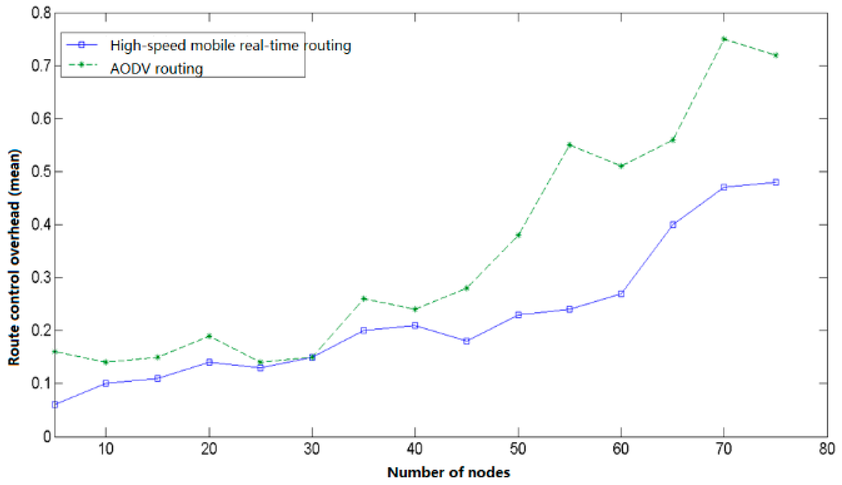
It can be seen from the above simulation results that when the number of nodes is small, the network control overhead of the routing algorithm designed in this paper is slightly smaller than AODV, and the difference is not significant. As the number of nodes increases, the control overhead of AODV grows significantly faster than the routing designed in this paper. When the number of nodes is 70, the control overhead of AODV reaches 0.75, namely, 75% of the bandwidth is used for network routing control, and the data transmission efficiency is low. In this case, the control overhead of the routing algorithm designed in this paper is only 0.48, indicating that nearly half of the bandwidth is used for video data transmission and the efficiency is significantly higher than that of AODV.
5. Conclusions
The effectiveness of the proposed networking scheme for the awareness combat network in this paper is verified by computerized numerical simulation of the awareness combat network. Each node in the awareness combat network is assigned a unique node ID in the entire network and the IP addresses of the nodes in the camp are planned to be in the same network segment. By combining cellular networks with Ad hoc, node state routing and mobile cellular routing are designed. The routing protocol supports QoS. The priority of information transmission in descending order is: voice, data, video for fire control, data, and ordinary video. According to the service type transmitted by the node, the corresponding routing algorithm is automatically selected according to the priority. Node states of the awareness combat network can be divided into “flat” state and “peak” state; the DTN overlay is added to the AODV protocol layer. Node state routing and mobile cellular routing complement each other. Compared with the traditional wireless mobile Ad-hoc network, the routing design scheme of the awareness combat network greatly improves the packet delivery rate, shortens the time delay, obviously reduces the network control overhead compared with the existing protocols, has a better anti-interruption performance, and is suitable for the application environment of the perceptual combat network.
Author Contributions
C.-H.W.: contributed to the conception, modeling, and algorithm design of the study, contributed to the analysis of simulation data, and approved the final manuscript. K.-Y.Q.: contributed to the conception and acquisition of simulation. P.L.: contributed to the analysis of simulation data. G.-H.W.: contributed to the modeling and Numerical Simulation Scenario Design of the study.
Conflicts of Interest
The authors declare that no conflicts of interest.
References
- Dai, H.; Yu, Q.; Wang, L.F. Design and implement simulation system in tactical mobile Ad-hoc network. Comput. Eng. Des. 2007, 28, 653–656. [Google Scholar]
- Su, J.S.; Hu, Q.L.; Zhao, B.K.; Peng, W. Routing techniques on delay/disruption tolerant networks. J. Softw. 2010, 21, 119–132. [Google Scholar] [CrossRef]
- Hu, Y.; Li, Z.; Liu, J. A Link stability prediction-based on-demand routing protocol in mobile Ad-hoc networks. J. Electron. Inf. Technol. 2010, 32, 284–289. [Google Scholar] [CrossRef]
- Patti, J.J.; Husnay, R.M.; Pintar, J. A smart software Radio: Concept development and demonstration. IEEE J. Sel. Areas Commun. 1999, 17, 631–649. [Google Scholar] [CrossRef]
- Reichhart, S.P. The software radio development system. IEEE Pers. Commun. 1999, 6, 20–24. [Google Scholar] [CrossRef]
- Lu, W.F.; Feng, M.; Wu, M. A Cellular Aided AODV routing protocol. J. Nanjing Univ. Posts Telecommun. (Nat. Sci.) 2008, 28, 23–29. [Google Scholar]
- Krifa, A.; Barakat, C.; Spyropoulos, T. MobiTrade: Trading content in disruption tolerant networks. In Proceedings of the 6th ACM Workshop on Challenged Networks, Las Vegas, NV, USA, 23 September 2011. [Google Scholar]
- McMahon, A.; Farrell, S. Delay- and Disruption-tolerant Networking. IEEE Internet Comput. 2009, 13. [Google Scholar] [CrossRef]
- Zhang, L.-L.; Li, C.-S. Comparison Analysis for MANET Routing Protocol. Chin. J. Electron. 2000, 28, 88–91. [Google Scholar]
- Palazzi, C.E.; Bujari, A.; Bonetta, S. MDTN: Mobile Delay/Disruption Tolerant Network. In Proceedings of the International Conference on Computer Communications and Networks, Maui, HI, USA, 31 July–4 August 2011; ISBN 978-1-4577-0638-7. [Google Scholar]
- Li, Z.; Yu, R.; Li, Q.M.; Liu, F.Y.; Zhang, H. Efficient Survivable MANET Routing Schema. Comput. Eng. 2011, 37, 126–128. [Google Scholar]
- Yan, L.-S.; Liu, S.-L. Application of DTN in naval data communication. Commun. Technol. 2009, 42, 197–200. [Google Scholar]
- Liu, Y.; Tang, Y.W.; Shao, X.T.; Li, X. Hybrid routing protocol for wireless multi-hop Ad Hoc networks. Acta Armament. 2017, 38, 184–189. [Google Scholar]
- Wang, T.; Wang, X.; Zhao, Z.; He, Z.; Xia, T. Measurement data classification optimization based on a novel evolutionary kernel clustering algorithm for multi-target tracking. IEEE Sens. J. 2018, 18, 3722–3733. [Google Scholar] [CrossRef]
- Ozger, M.; Alagoz, F.; Akan, O.B. Clustering in Multi-Channel Cognitive Radio Ad Hoc and Sensor. IEEE Commun. Mag. 2018, 56, 156–162. [Google Scholar] [CrossRef]
- Chen, Z.; Zhang, X.; Ding, G. Continuous Sensing Information Based Generalized Framework in Cognitive Radio. J. Beijing Univ. Posts Telecommun. 2015, 38, 100–104. [Google Scholar]
- Bai, Y.; An, J.; Zhang, H.-B. Prediction-Aided Routing Protocol in Ad hoc Network. J. Beijing Univ. Posts Telecommun. 2017, 40, 29–33. [Google Scholar]
- Sankar, S.; Sankaranarayanan, V. A predictive route maintenance protocol based on signal strength for dense Ad hoc networks. Int. J. Comput. Theory Eng. 2012, 4, 570–574. [Google Scholar] [CrossRef]
- Yadav, A.; Singh, Y.N.; Singh, R.R. Improving routing performance in AODV with link prediction in mobile Ad hoc networks. Wirel. Pers. Commun. 2015, 83, 603–618. [Google Scholar] [CrossRef]
- Alsaqour, O.; Alsaqour, R.; Alahdal, T.; Saeed, R.; Al-Hubaishi, M. A comparative study of simulation based performance evaluation of routing protocol for ad hoc networks. In Innovations and Advances in Computing, Informatics, Systems Sciences, Networking and Engineering; Lecture Notes in Electrical Engineering; Springer: Cham, Switzerland, 2015; Volume 313, pp. 215–221. [Google Scholar]
- Saleh, A.I.; Arafat, H.; Hamed, A.M. An Adaptive hybrid routing strategy (AHRS) for mobile ad hoc networks. Peer-to-Peer Netw. Appl. 2018, 11, 561–578. [Google Scholar] [CrossRef]
- Naeem, M.K.; Patwary, M.; Abdel-Maguid, M. Universal and Dynamic Clustering Scheme for Energy Constrained Cooperative Wireless Sensor Networks. IEEE ACCESS 2017, 5, 12318–12337. [Google Scholar] [CrossRef]
Figure 1.
Closed-loop routing control model of the awareness combat network.

Figure 2.
Awareness combat network with planar peer-to-peer structure.

Figure 3.
Packet format.

Figure 4.
Schematic diagram of packet transmission.

Figure 5.
AODV-DTN flooding using geographic location information.

Figure 6.
Data transmission diagram of awareness combat network routing (“flat” state).

Figure 7.
DTN initialization module processing and main control process.

Figure 8.
Sending of the DTN package process.

Figure 9.
Receiving of the processing of the DTN package process.

Figure 10.
Routing discovery process.

Figure 11.
Determining the destination node.

Figure 12.
Operation results of the simulation system.

Figure 13.
Distance between source and destination nodes.

Figure 14.
Ping success rate of a node when the number of nodes is different.

Figure 15.
Routing Control Overhead.


Table 1.
Basic parameter settings for simulation.
| Parameter | Value | Remarks |
|---|---|---|
| Name of simulation scenario | Tactical Sensor Network | Animation update period for the scene: 0.1 s |
| Simulation time display accuracy | 0.1 ms | |
| Simulation time | 3000 s | |
| Simulation area | 20 km × 20 km | Map background |
| Initial number of nodes | 21 | |
| Node communication range | ≤2 km | The initial value, can be changed to 10 km during simulation |
| Antenna type | Omnidirectional antenna | |
| Routing model | DTN-AODV | DTN-AODV.class |
| Node movement rate | 0~10 m/s | Random value |
| Mobility model | Integrated mobility model | Map-based road data |
| DTN overlay cache | 5 MB | |
| Service type | Data | Ping application, video data |
| Network Management Mode | Cooperation | Awareness combat network |
© 2018 by the authors. Licensee MDPI, Basel, Switzerland. This article is an open access article distributed under the terms and conditions of the Creative Commons Attribution (CC BY) license (http://creativecommons.org/licenses/by/4.0/).
Share and Cite
MDPI and ACS Style
Wu, C.-H.; Qin, K.-Y.; Li, P.; Wu, G.-H. The Dynamic Routing Protocol Implementation Strategy of the Cooperative Control Awareness Combat Network. Appl. Sci. 2018, 8, 948. https://doi.org/10.3390/app8060948
AMA Style
Wu C-H, Qin K-Y, Li P, Wu G-H. The Dynamic Routing Protocol Implementation Strategy of the Cooperative Control Awareness Combat Network. Applied Sciences. 2018; 8(6):948. https://doi.org/10.3390/app8060948
Chicago/Turabian StyleWu, Cheng-Hai, Kai-Yu Qin, Ping Li, and Guo-Hui Wu. 2018. "The Dynamic Routing Protocol Implementation Strategy of the Cooperative Control Awareness Combat Network" Applied Sciences 8, no. 6: 948. https://doi.org/10.3390/app8060948
Note that from the first issue of 2016, this journal uses article numbers instead of page numbers. See further details here.