Thermal Characterisation of Micro Flat Aluminium Heat Pipe Arrays by Varying Working Fluid and Inclination Angle


1
Key Laboratory of Surface Functional Structure Manufacturing of Guangdong Higher Education Institutes, School of Mechanical and Automotive Engineering, South China University of Technology, Wushan Road, Guangzhou 510640, China
2
Department of Mechanical Engineering, University of South Carolina, Columbia, SC 29208, USA
*
Author to whom correspondence should be addressed.
Appl. Sci. 2018, 8(7), 1052; https://doi.org/10.3390/app8071052
Submission received: 3 June 2018
/
Revised: 19 June 2018
/
Accepted: 27 June 2018
/
Published: 28 June 2018
(This article belongs to the Special Issue New Heating and Cooling Concepts)
Abstract
:Featured Application
solar collector; solar thermal system; thermal energy storage system; heat exchanger.
Abstract
A micro heat pipe array is desirable owing to its high heat transfer capacity, compact size, and high surface–volume ratio compared with conventional heat pipes. In this study, micro flat aluminium heat pipe arrays (MF-AHPA) were developed and systematically characterised by varying working fluid and inclination angle. Three MF-AHPAs with different working fluids, i.e., acetone, cyclopentane, and n-hexane, were fabricated. The acetone MF-AHPA achieved the best thermal performance. The underlying mechanism is the small flow viscous friction and small shearing force of liquid vapour. Additionally, the experimental results show a strong dependence of MF-AHPAs’ thermal resistance on the orientation due to the gravitational effect on axial liquid distribution. Finally, a criterion is proposed to determine the optimal inclination angle of the MF-AHPA. In the present study, a volumetric fraction (αa,c) of 74 ± 7% has been shown to well predict an optimal inclination angle of the MF-AHPAs with various working fluids and heat loads.
1. Introduction
Heat pipes are widely used in the application of solar energy [1], which is a cost-effective and green energy resource for space heating [2], distillation [3], and absorption chillers [4]. In traditional solar thermal systems, round copper heat pipes are applied to the solar heat collectors [5,6,7]; however, this type of heat pipe is not a desired solution due to its high weight, small surface–volume ratio, and large size [8]. A novel micro flat aluminium heat pipe array (MF-AHPA) [9] provides a promising method for significantly improving solar heat collection due to its high in-plane thermal conductivity, high reliability, strength, and relatively low cost.
The concept of micro heat pipes was proposed by Cotter et al. in 1984 [10]. A micro wick with a high surface–volume ratio shows potential heat transfer coefficient enhancement [11]. In past decades, extensive studies have been conducted because it outperforms a regular heat pipe. However, the heat transfer capacity of a single micro heat pipe is restricted by its relatively smaller cross-sectional areas. A micro heat pipe array can drastically enhance the heat transfer capacity due to its high surface–volume ratio. A micro heat pipe array was firstly investigated on silicon substrates [12,13]. Aluminium extrusion provides a feasible and cost-effective technique to fabricate MF-AHPAs.
Most recently, the solar thermal systems using MF-AHPAs demonstrated substantially enhanced performances. For example, Deng et al. developed a flat plate solar collector using a MF-AHPA to achieve a maximum efficiency of 80%, accounting for 25% enhancement over the average efficiency on other alternatives [8]. Zhu et al. developed a solar air heater using flat micro heat pipe arrays. The average thermal efficiency of the novel solar air heater was reportedly up to 70% [14] and 73% [15] during steady-state operations, which is significantly better than a traditional flat plate heater. The micro heat pipe array also presented good performance in solar concentration thermoelectric generators [16], solar photovoltaic–thermal systems [17,18], thermal energy storage systems [19], solar air collectors [20,21], and heat exchangers [22].
Although the performance of a thermal system integrated with micro heat pipe arrays has been extensively studied, the micro heat pipe array has not been well characterised. The length–diameter ratio of the MF-AHPA is as high as 808.3, far surpassing the conventional heat pipe values of 51.5 [23], 50 [24], and 33.3 [25]. Knowledge of the heat transfer characteristic of heat pipes with such a high length–diameter ratio is insufficient in literature. In particular, the effect of orientation on MF-AHPA performance should be quantified, considering their critical roles in determining the efficiency of thermal systems [26]. In addition, working fluids have been known to play a critical role in governing heat pipe performance, no matter whether they are in an oscillating heat pipe [27] or a loop heat pipe [28]. However, study on working fluids on aluminium heat pipes is still insufficient. It is needed to systematically characterise the orientation and effect of working fluids on such aluminium micro heat pipe arrays.
It is significant to investigate the effect of the inclination angle and working fluid on the MF-AHPA, since both can improve the efficiency of a solar collector. The optimal orientation of a solar collector well balances the heat pipe thermal resistance and light absorption efficiency. The inclination angle results of the MF-AHPA provide guidance on designing the orientation of a solar thermal collector. Furthermore, the mechanism of working fluid property and liquid film distribution will be analyzed to better understand the principle of selecting working fluid and inclination angle. Finally, the best thermal performance of the MF-AHPA will be achieved.
The optimal inclination angle of heat pipes is significant, and has attracted extensive interest. However, reported optimal inclination angles of heat pipes varies significantly such as 30° [29], 45° [30], 60° [31], 75° [23], or 90° [32]. No criterion has been proposed to determine the optimal inclination angle for different types of heat pipes. It is challenging to accurately predict the optimal inclination angle of heat pipes with various working fluids and heat loads. Therefore, a criterion to predict the optimal inclination angle of heat pipes is demanded.
This study firstly systematically characterized the thermal performance of the MF-AHPA, of which the thermal characteristics are different from those of conventional round or flat plate heat pipes. The MF-AHPA has a higher condensation rate and extremely longer liquid return path due to high surface–volume ratio and length–diameter ratio. Three experimental setups were designed and built to characterise the heat pipe start-up features and thermal resistance, respectively. Furthermore, the liquid film thickness profiles of heat pipes with various inclination angles are modelled. This research firstly discovered and verified the potential relationship between the optimal inclination angle and liquid film distribution. A criterion is also originally proposed to quantificationally predict the optimal inclination angles of the MF-AHPAs with various working fluids and heat loads.
2. Design, Working Fluid, and Experimental Apparatus of the MF-AHPA
2.1. Design of the MF-AHPA
As shown in Figure 1, extruded from 1100 aluminium, a 26-mm wide and 970-mm long MF-AHPA consists of nine parallel microchannels with a 3-mm thick shell. Note that these channels are fully separated by inner ribs. Once they are charged, these individual channels can work independently as heat pipes. The inner ribs also serve as fins, with an estimated fin efficiency of 67% when the heat transfer coefficient is 16,000 W/m2∙K. Also, 0.32-mm deep microgrooves are extruded on the upper and bottom walls, which can greatly prompt capillarity and substantially increase the surface area for evaporation or the condensation heat transfer rate. The specific dimensions of the cross-section are detailed in Table 1.
The depth–width ratio is an important parameter for evaluating the groove quality of heat pipes. For example, a narrow and deep groove can generate larger capillary pressure and enhance the heat transfer limit, but results in a higher thermal resistance due to the formation of thicker liquid films. Kim [33] found that in a rectangular grooved wick heat pipe, a groove height ratio of 1.4 and groove width ratio of 1.1 achieved a well-balanced heat pipe performance, i.e., a small thermal resistance and high heat transport limit. In this study, the depth–width ratio of grooves is designed and fabricated as 1.28 (0.32 mm/0.25 mm), which is close the optimal value of 1.27 (1.4/1.1) according to Kim’s study [33].
The configuration and working mechanism of a MF-AHPA are also schematically shown in Figure 1. Liquid return is improved by additional capillary pressure generated by the microgrooves. Since an individual channel works independently as a heat pipe, the MF-AHPA is more tolerable to leakage and non-condensable gas, and hence becomes more reliable than conventional heat pipes.
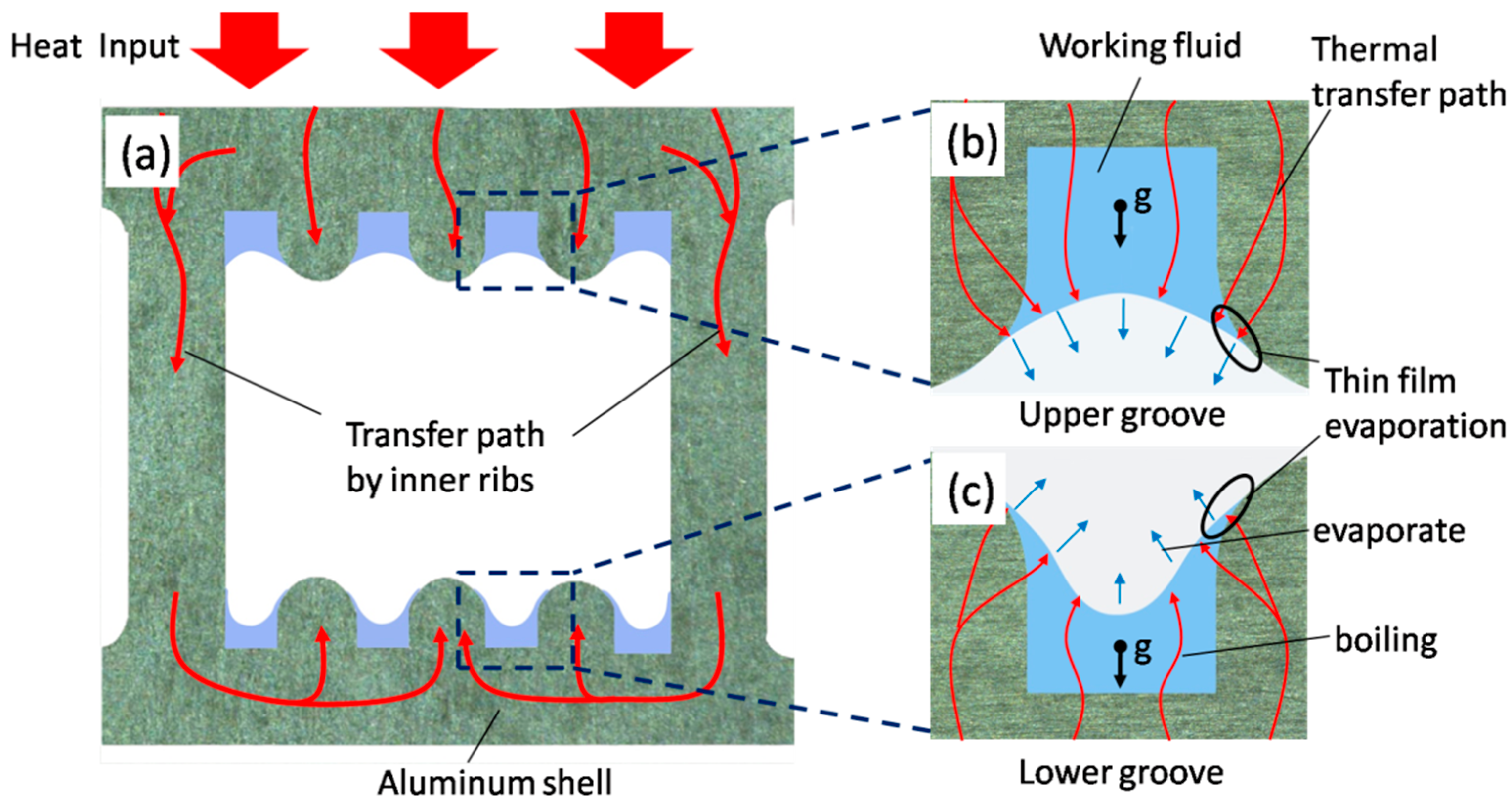
The heat spreading is supposed to be significantly enhanced by the inner ribs in the present design. Figure 2 schematically presents the heat transfer path and liquid film distribution in grooves when heated from the upper surface as a solar collector in solar thermal systems. Without the inner ribs, evaporation only occurs on the heating side. With the integration of inner ribs acting as fins, heat can spread from the upper surface to the bottom surface, as schematically shown in Figure 2. Thus, evaporation can be extended on all of the inner surface areas, which at least doubles the evaporating areas and can greatly enhance the overall heat transfer rate [34,35].
2.2. Working Fluids Selection and Evaluation
2.2.1. Working Fluids Selection and Charging Processes
Working fluids would be a key factor in the performance of the present design. According to the compatible principle, ammonia [36], Freon, cyclopentane [37], acetone [38], and n-hexane are used as working fluids for aluminium heat pipes. However, ammonia and Freon are only applicable for low temperature heat pipes. In this study, cyclopentane, acetone, and n-hexane are selected for the MF-AHPA working at regular temperature. The properties of the selected working fluids are listed in Table 2.
Acetone has potential to show good thermal performance due to its high thermal conductivity and large latent heat of vaporisation. Since the boiling point is as low as 49 °C at 1 atm, cyclopentane tends to phase change and works at a lower temperature. N-hexane, with its relatively large density of vapour, has the potential to reduce the vapour velocity and the liquid–vapour shearing force.
The filling rate of working fluid can be defined as [39]:
where vwf is the volume of the working fluid and vg is the volume of the grooves. In this study, the filling rates of the three working fluids were all 100% (6.4 mL), meaning that the grooves are full of working fluid. The aluminium grooved tube was ultrasonically cleaned by ethanol, acetone, sulfuric acid, and deionised water for 10 min sequentially. After air-drying at room temperature, the cleaning process was finished. The purity of working fluids used in this study was more than 99.5% and a 10-min degassing process was conducted. Before charging, pipes were vacuumed to be lower than 10 Pa in the first vacuum process. The second vacuum process [39,40] was adopted to minimise non-condensable gas. A non-condensable gas gathering section with a length of 80 mm was sealed off after heating the evaporation section in 100 °C for 60 s.
η = vwf/vg × 100%
The heat pipe performance is affected by many other factors, including non-condensable gas (NCG) [41], charging ratio [42], and groove wick structure [33]. Heat pipe performance is very sensitive to the amount of NCG. Only 5% NCG could induce a reduction of 50% in condensation heat transfer coefficient [43]; an excessive charging ratio leads to flooding in the condenser, whereas an insufficient working fluid induces dry-out in the evaporator; a groove with a high depth–width ratio has a higher critical heat flux, but a lower heat transfer coefficient. Although heat pipe thermal performance is affected by other factors, the variable factor in this comparative experiment is inclination angle or working fluid. The obtained results are credible by keeping other parameters the same.
2.2.2. Evaluation of the Working Fluids
A group of parameters that could help understand the effect of working fluid properties on heat pipes were calculated including flowing viscous friction (Fl), inertial vapour force factor (finv), Bond number (Bo), Galilei number (Ga), and Laplace number (La), as shown in Table 3. The definitions and formulae of each parameter are detailed as follows.
The flowing viscous friction of the working fluid in the grooves by transferring unit power (Fl) [44] is defined as:
where μl is the dynamic viscosity of the liquid, K is the permeability, Aw is the wick cross-sectional area, ρl is the liquid density, and hfg is the latent heat of vaporisation.
The vapour exerts a shear force at the interface between the vapour and the wick surface. This action would entrain droplets back into the condensation section. The inertial vapour force factor (finv) represents the magnitude of inertial vapour force produced by the properties of working fluid. It is defined as [44]:
The Bond number is defined as the ratio of gravitational forces and surface tension force. A low Bond number indicates that surface tension effect dominates [45]. It is calculated by:
where rhl is the hydraulic radius of the groove.
The Galilei number presents the ratio of gravitational forces and viscous force, which is expressed by:
The Laplace number is the ratio of surface tension and momentum diffusivity, which is calculated by:
The calculated parameters of working fluids are closely related to the heat pipe performance. The Ga number presents the flowing capacity of working fluid driven by gravity only. The inertial vapour force factor (finv) reflects the flow friction of working fluid vapour in the vapour channel. As shown in Table 3, acetone is supposed to have the smallest liquid–vapour shearing force due to the smallest finv value of 1.57 × 10⁻¹² m3kg/J2. The liquid spreading that is driven only by capillary pressure could be evaluated by the La number. The viscous friction (Fl) reflects the flow resistance in wicks for a given heat load. The working fluid with a smaller Fl corresponds to a larger heat transfer limitation [46]. In addition, as reported by O.T. Ibrahim et al. [27], a working fluid with a low La number correlates to a lower heat transfer capacity. A liquid with a large La number may have better local temperature uniformity if a capillary wick is applied. Thus, acetone, with the smallest Fl (230 N·s/m3∙J), finv (1.57 × 10⁻¹² m3kg/J2) and largest Ga (621.2) and La (50,205), is supposed to have a relatively higher heat transfer capacity, better drainage of condensation liquid, and local temperature uniformity.
2.3. Experimental Apparatus and Processes
2.3.1. Test Setup to Characterise Heat Pipe Start-Up Temperature
Figure 3 presents the test setup for start-up performance. A 970-mm long heat pipe was placed by a support with adjustable inclination angle. The evaporation section was immersed in a hot water tank at a constant temperature of 55 °C, while the condensation section was exposed at an ambient temperature of 28 °C. The length of the heat pipe immersed in the water tank was 200 mm with a Pt100 resistance thermometer used to test the temperature of point Tc. The response time is defined as the time needed to reach 63.2% of the temperature in steady state [47]. Agilent 34970 was used to acquire data at a sampling rate of 1 Hz.
2.3.2. Evaluation of Heat Pipe Temperature Uniformity during Start-Up
As shown in Figure 4, a setup was designed to evaluate heat pipe temperature uniformity during start-up using an infrared camera. The test system consists of a thermostatic water tank, an infrared camera, and a personal computer. The IR camera model was FLIR ThermaCAM SC300 (FLIR Systems Inc, North Billerica, MA 01862, USA), with an accuracy of ±2 °C and resolution of 320 × 240 pixels. When the test started, the three heat pipes with different working fluids were immersed into the thermostatic water tank at 55 °C. The length of the section immersed in the water was 200 mm. The infrared camera recorded the temperature distribution for more than 2 min.
2.3.3. Experimental System to Characterise Heat Pipe Thermal Resistance
The thermal resistance of the MF-AHPA was experimentally evaluated with various inclination angles in the test setup, as shown in Figure 5. The lengths of the evaporation section, adiabatic section, and condensation section are specified in Figure 5. The experiment was operated at an ambient temperature of 28 °C without forced air convection. The specifications of the instruments used in this system are listed in Table 4.
The experimental system consisted of three sub-systems:
1. Heating sub-system
A constant 220 V voltage was provided by a TND-1500VA automatic AC voltage stabiliser with an AC voltage regulator. The evaporation section was heated by a pair of copper blocks. Input heat was measured by a TOS120A power meter. To reduce the heat loss, both the evaporation and adiabatic sections were well insulated. The evaporation section was insulated by three-layer fiberglass insulations with aluminium foil as the surface. The insulation had a total thickness of 15 mm and an exposed surface area of 0.07 m2. With a fiberglass thermal conductivity of 0.03 W/m∙K, the heat loss of the insulation was estimated to be between 2.8 W and 4.6 W in different operating temperatures ranging from 48 °C to 65 °C.
2. Cooling sub-system
A thermostatic tank provided constant-temperature water of 45 ± 0.1 °C to cool the condensation section. The flow rate of the cooling water was carefully controlled by a float flowmeter to stabilise the condenser section temperature.
3. Data acquisition sub-system
As shown in Figure 5, six Pt100 type resistance thermometers were used to measure the evaporator section temperature (TE1, TE2, TE3) and condenser section temperature (TC1, TC2, TC3). All of the temperatures were automatically monitored and collected by an Agilent 34970A and a personal computer (PC). Experimental data were recorded for 3 min at a sampling rate of 1 Hz.
2.3.4. Data Reduction
The average temperature of the evaporator section is calculated as:
The average temperature of the condenser section is calculated as:
The thermal resistance of a heat pipe is defined as:
The optimal inclination angle in this study is defined as the angle at which the minimum thermal resistance of heat pipe is achieved.
2.3.5. Uncertainty Analysis
The absolute measurement uncertainty of tested temperature is ±0.5 °C. The average temperature TE and TC have an uncertainty of ±0.5 °C. The uncertainty of the response time was estimated to be within 1 s. According to a standard error analysis method proposed by Taylor [48], the relative uncertainty of thermal resistance was calculated to be ±3.0%~4.6%, as presented in the error bars in Figures 9 and 10.
3. Liquid Film Distribution Model
3.1. Liquid Film Thickness in the Condensation Section
To further understand the mechanism of inclination angle, the thickness of the liquid film was calculated by a mathematic model in this study. The condensation model in heat pipes is different from the well-known Nusselt model [49]. The large shear stress induced by high speed vapour flow is considered in this heat pipe condensation model [50]. The model of heat pipe condensation liquid film distribution could be derived as follows. The derivation is based on perfect liquid distribution without considering the uneven thickness caused by entrained droplets. According to the conservation law of momentum and energy, we have the following governing equations:
The boundary conditions are:
where u is the velocity; Twc is the wall temperature; Ts is the vapour temperature; τi is the shear stress; δ is the liquid film thickness; and y is the position at normal direction of the wall.
In Equations (10), g′ is the corrected gravitational acceleration, which includes the effect of inclination angle and capillary pressure. The determination of g′ could be solved by the below equation:
where Leff is the effective length of the heat pipe, β is the heat pipe inclination angle, and Pc is the capillary pressure generated by the wick.
From equations (10)–(13), the following relationship could be expressed:
The C1, C2, and C3 are defined as:
where ui is the interfacial velocity, Г is the mass flow rate per unit width of liquid film, νl is the kinematic viscosity, and kl is the thermal conductivity of liquid.
The shear stress τi is calculated by the equation:
where τf is shear stress due to friction force, τm is shear stress due to mass transfer, and cf is the frictional coefficient.
The velocity of vapour is calculated by:
where Dv is the hydraulic diameter of vapour channel.
The heat transfer rate of condensation is expressed as:
where the local heat transfer coefficient determined by liquid film thickness is calculated by: h = λl/δ.
3.2. The Volumetric Fraction of Working Fluid (αc,a)
In order to better quantify the amount of working fluid needed for evaporation, we define a ratio αc,a to present the volumetric fraction of working fluid filled in condensation and the adiabatic wicks:
where Vliquid is the volume of working fluid filled in condensation and adiabatic sections, and Vgroove is the volume of grooves in condensation and the adiabatic sections. If αc,a = 100%, the grooves are completely filled with working fluid in condensation and the adiabatic sections.
The Vliquid in condensation and the adiabatic sections can be calculated by:
where the δ(x) can be obtained by the previous liquid thickness profile model.
3.3. Validation of the Liquid Film Distribution Model
Figure 6 shows a validation of the present liquid film model with CFD (Computational Fluid Dynamics) results by A. Alizadehdakhel et al. [51] and Nusselt’s model. In the present model, the vapour velocity vectors were assumed to be tangent with the liquid surface, and the film profile was smooth. In CFD simulation using the VOF (volume of fluid) model, some local vapour velocity vectors were radial and caused additional impact on the surface of the liquid film, resulting in fluctuations on the liquid surface. Although the CFD results fluctuated more than the present model results, the CFD results obtained by A. Alizadehdakhel et al. agreed with the present model in terms of the same order of magnitude (0.03–0.15 mm) and trend. Compared with Nusselt’s model, as shown in Figure 6b, the film thickness calculated by the present model is slightly thicker than Nusselt’s prediction; this could be attributed to the liquid–vapour shearing stress considered in the present model. The comparisons illustrated that the present model reasonably agrees with the CFD results and Nusselt’s model.
4. Results and Discussion
4.1. Characterisation of Heat Pipe Start-Up Performance
Figure 7 presents the effect of working fluid on the start-up performance of the MF-AHPAs in a vertical orientation. The thermal response curves show that the working fluid greatly affects the start-up performance of the MF-AHPA. As shown in Figure 7, the acetone MF-AHPA responds the fastest among all of the tested samples. After approximately 65 s, the acetone MF-AHPA nearly reached the steady state. The response times of the acetone, cyclopentane, and n-hexane MF-AHPAs are 16 s, 29 s, and 46 s, respectively. The results suggest that working fluid with a high Ga value is desirable to shorten the response time. For example, with the maximum Ga number of 621.2, the viscous force of acetone is relatively smaller and can be overcome by the gravitational force. Thus, the acetone MF-AHPA has a faster liquid returning process from the condensation section to the evaporation section. As a result, the acetone MF-AHPA responds much faster than the other two heat pipes.
Figure 8 presents a series of infrared camera (IR) images of the three MF-AHPAs with different working fluids during the start-up process in a 15-s interval. The water bath was set at 55 °C with an ambient temperature of 28 °C. The axial temperature distribution is described by colour contours with the maximum temperature represented by a white colour. In the start-up process of the n-hexane MF-AHPA, the temperature rose very quickly in the evaporation section, while the temperature of the condensation section remained unchanged in the first 10 s. Then, the condensation section was slowly heated up. In the acetone and cyclopentane MF-AHPAs, the temperatures of entire pipes were relatively uniform after heat was applied. The acetone and cyclopentane MF-AHPAs outperformed the n-hexane MF-AHPA in terms of temperature uniformity. This could be caused by the low latent heat of evaporation and large vapour density of n-hexane, as specified in Table 2. For example, the latent heat of n-hexane is as low as 66.3% of acetone, but the vapour density is as high as 148.1% of acetone. The low latent heat of evaporation means a smaller amount of vapour to be generated for a given working load; while a large vapour density leads to a large vapour inertia force on n-hexane. These two factors would result in high vapour flow resistance and an insufficient vapour supply consequently lowering the condensation rate.
4.2. Effect of Working Fluids on Heat Pipe Thermal Resistance
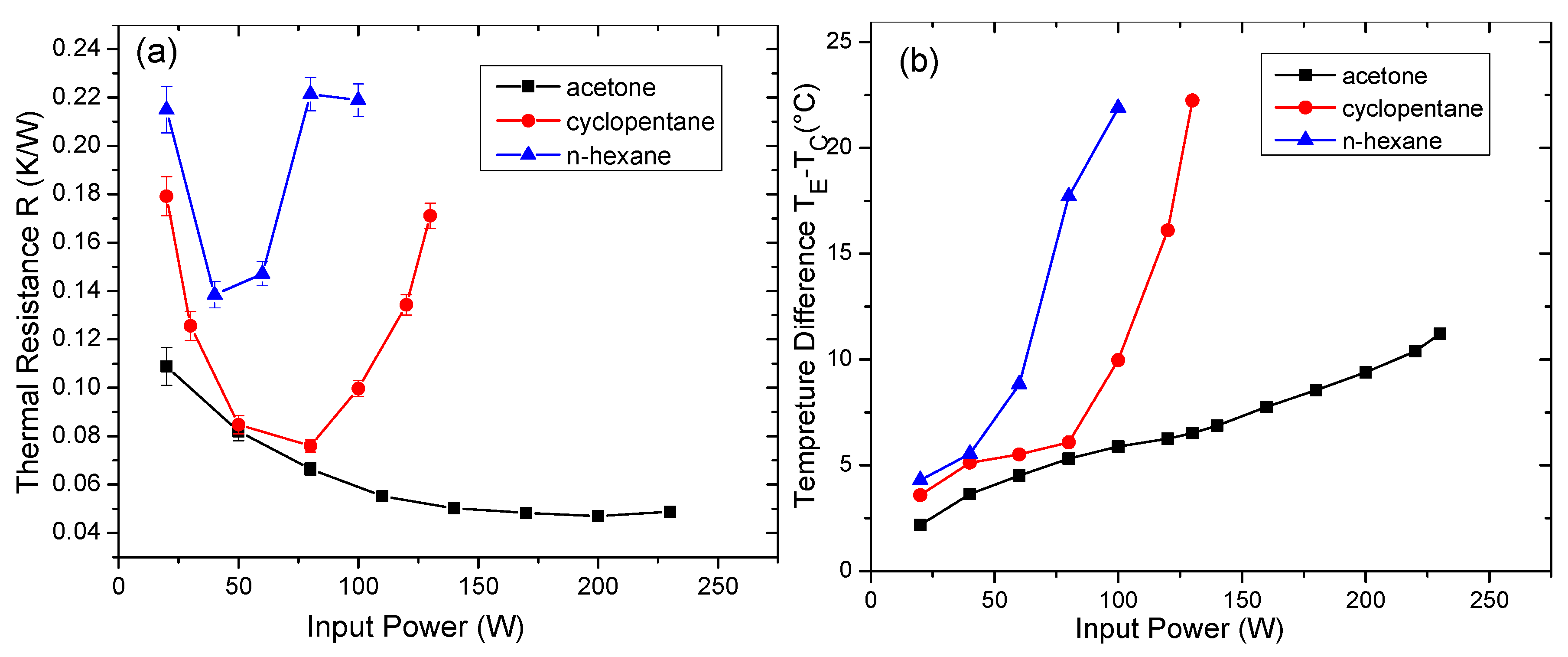
Figure 9 shows the thermal resistance and temperature difference (TE − TC) of the tested MF-AHPAs with different working fluids at an inclination angle of 45°. The thermal resistance of the acetone MF-AHPA reduced continuously and significantly as the heat load was increased up to 140 W. Between 140–230 W, the reduction of thermal resistance was insignificant and appeared to reach a minimum value. However, the thermal resistance curves of the cyclopentane MF-AHPA and n-hexane MF-AHPA are U-shaped, and different from the acetone one, meaning an occurrence of partial dry out after reaching minimum thermal resistances (MTRs). At high heat flux, the cyclopentane MF-AHPA and n-hexane MF-AHPA significantly suffered from local dry-out, resulting in a decreased heat transfer coefficient in the evaporation section [23]. Local dry-out could reduce an evaporation heat transfer coefficient by more than 25%. However, this didn’t occur in the acetone heat pipe. Acetone, with the highest La number of 50,205, has a relatively high surface tension. Liquid acetone could spread quickly in the evaporation region due to strong capillarity, managing unwanted local dry-out well, and maintaining the desired performance.
The MTRs of the acetone, cyclopentane, and n-hexane heat pipes are 0.048 K/W, 0.076 K/W, and 0.140 K/W, respectively. The MTR of the acetone MF-AHPA was 34% and 63% lower than these of n-hexane and cyclopentane ones, respectively. This illustrates that the working fluid plays a critical role in determining the thermal resistance of the MF-AHPAs. Acetone is the best working fluid among the selected three ones, which achieves the smallest thermal resistance at all of the working loads in this study. This should be because of its favourable thermophysical properties including low viscosity, high thermal conductivity, and a high latent heat of vaporisation.
4.3. Effect of Inclination Angle on the Thermal Resistance of the Heat Pipe
Figure 10 presents the effect of inclination angle on the thermal resistance of the MF-AHPAs. It is obvious that the inclination angle plays a significant role in determining the thermal resistance for all of the heat pipes with different working fluids. For example, the thermal resistance of acetone heat pipes is strongly affected by inclination angles for a given heat load. For example, at a heat load of 50 W, the thermal resistance increased from 0.063 K/W to 0.083 K/W as the inclination angle rose from 10° to 75°. The thermal resistance could have a reduction of 24% by working on the optimal inclination angle in this case.
As shown in Figure 10b, U-shaped thermal resistance curves were observed, indicating an existence of a critical heat load to realise the best performance. The critical heat load increased as the inclination angle increased. The optimal inclination angle also depends on the heat load. The optimal inclination angle of the cyclopentane MF-AHPAs is 25° for heat loads from 0 W to 50 W, while it increased to 75° with heat loads ranging from 50 W to 160 W. As shown in Figure 10c, the optimal inclination angle of the n-hexane MF-AHPA is 75° with heat loads larger than 60 W. However, with the heat load between 20–40 W, it was difficult to determine an optimal inclination angle. It appeared to be between 45–75° due to overlapped error bars. The mechanisms of orientation effect will be explained in the following section.
4.4. Mechanisms of the Effect of Inclination Angle on Heat Pipe Performance
The mechanisms in the literature to explain how the inclination angle affects the heat pipe performance are limited. It has been widely accepted that an insufficient or excessive inclination angle could harm the heat pipe performance [30]. An insufficient inclination angle may induce a poor return of backflow to the evaporator [52], while an excessive inclination angle will reduce the heat dissipation efficiency by decreasing the heat exchange time at the condenser [31,52]. However, a quantitative prediction of the optimal inclination angle is still lacking. In this study, we are trying to obtain the optimal inclination angle from the perspective of the liquid film profile in the condensation section. It could provide a general criterion to explain various optimal inclination angles of the MF-AHPAs with different working fluids and heat loads.
4.4.1. Liquid Film Profile of the MF-AHPAs
The heat pipe thermal performance is strongly affected by liquid film thickness. In the condensation section, an increase of the condensate thickness would lead to a degradation of heat transfer coefficient, and consequently a higher thermal resistance [51,53]. In the evaporation section, a higher height of liquid pool in evaporator hinders the formation of larger bubbles or film, as presented in the CFD result by Alizadehdakhel et al. [51], which is unfavourable to the evaporation heat transfer rate, and hence heat pipe performance.
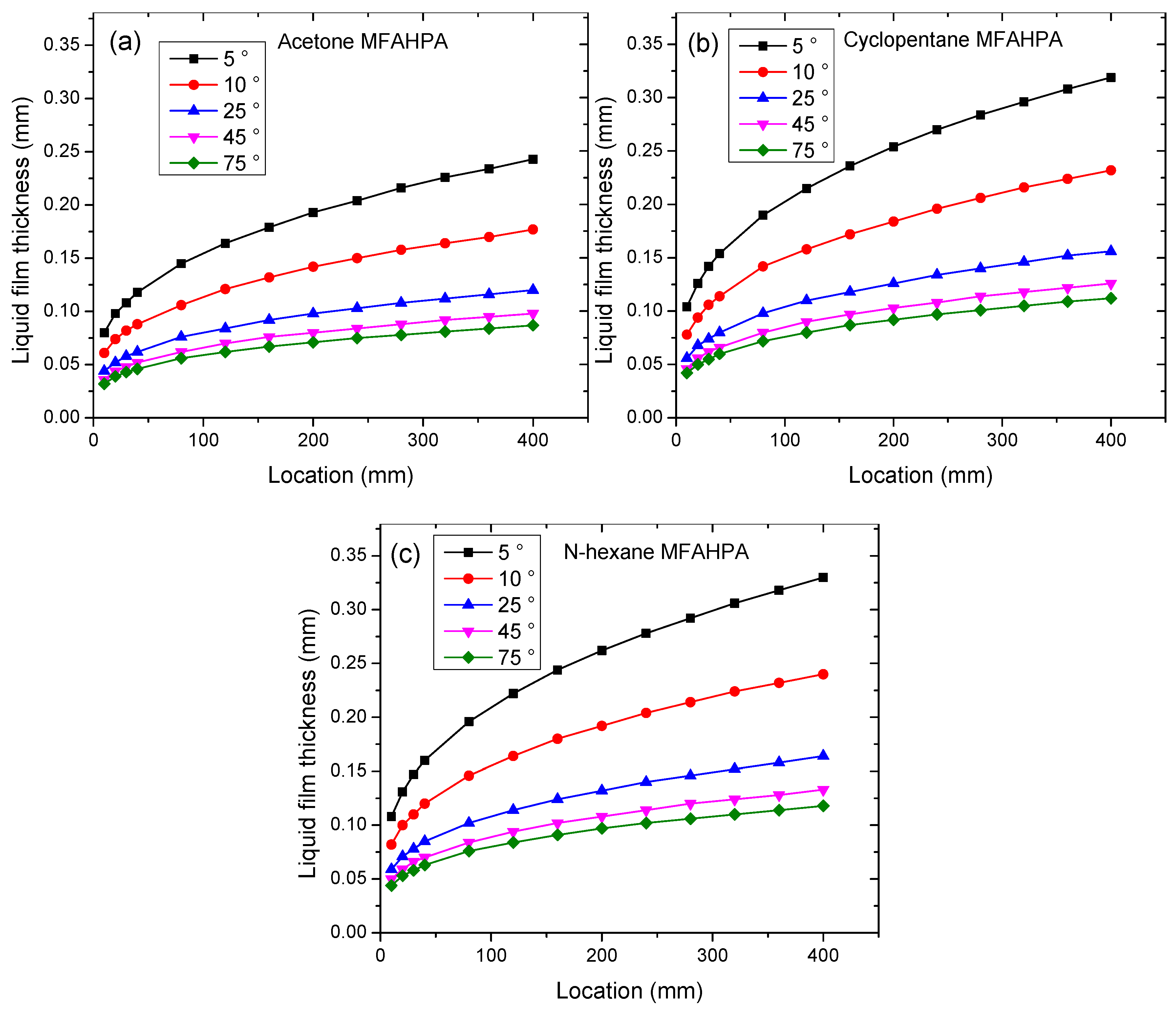
Figure 11a–c present the effect of inclination angle on liquid film profile in the condensation section of the MF-AHPA with various working fluids at 90 W. The thickness of liquid film during condensation is developing from the side and growing as the condensate flows toward the evaporation section. As shown in Figure 11, the thickness of condensate decreases as the inclination angle increases, owing to the increasing influence of gravitational force. Due to the relatively smaller viscous friction factor (Fl) and inertial vapour force factor (finv), the acetone liquid film is shown to be thinner than those of the other two working fluids.
4.4.2. Relationship between Optimal Inclination Angle and Volumetric Fraction (αc,a)
There may be a relationship between the optimal inclination angle and volumetric fraction (αc,a). The optimal inclination angle can be determined by a minimum combined thermal resistance of evaporation and condensation processes. In fact, a universal optimal inclination angle does not exist. It varies with the working fluids, wicking structure, and heat loads. For example, at 90 W, the optimal inclination angle of the acetone heat pipe is 25°, but it becomes 75° for both the n-hexane and cyclopentane heat pipes. In addition, the optimal inclination angle may be different in various heat loads, even for the same heat pipe. For example, the optimal inclination angles of the acetone heat pipe with heat loads of 40 W, 90 W, 160 W, and 230 W are 10°, 25°, 45°, and 75°, respectively.
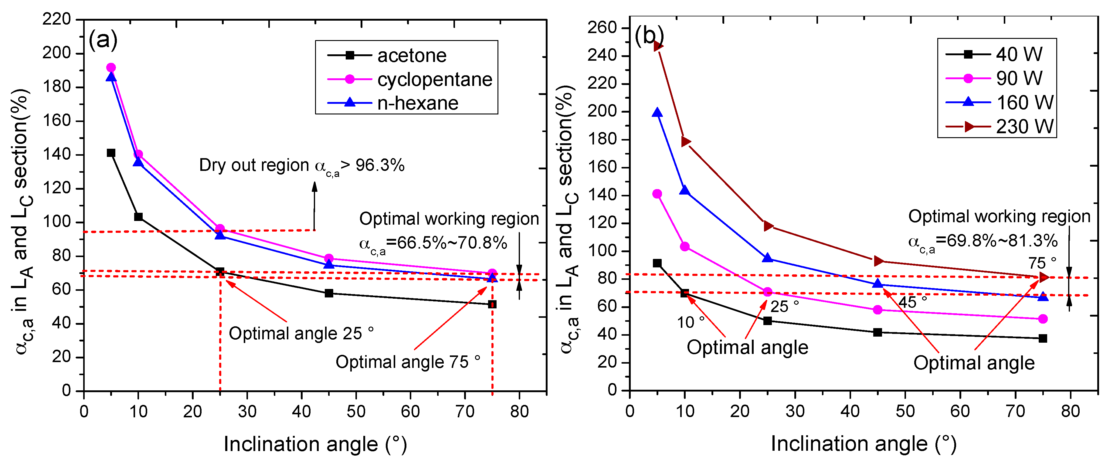
In order to figure out the mechanism or criteria in determining an optimal inclination angle, the volumetric fraction, αc,a (Equation (22)), which represents a fraction of working fluid in the section of condensation and adiabatic wick, is introduced. Figure 12 plots αc,a as a function of the inclination angle. The effect of working fluid and heat load on the volume fraction αc,a are shown in Figure 12a,b, respectively.
Although the optimal angles vary significantly for heat pipes with different working fluids or heat loads, we observed that the corresponding volume fractions αc,a show a very small variation, i.e., from 66.5% to 81.3%. Specifically, in Figure 12a, the αc,a changes slightly from 66.5% to 70.8% when a large change of the optimal inclination angles with different working fluids, i.e., varying from 25° to 75°. The same trend can be observed in Figure 12b for the acetone heat pipe at various heat loads. Experimental results clearly illustrate that the optimal inclination angle is strongly related to the liquid volumetric fraction αc,a. It appears that the mean value of the selected optimal volumetric fractions is 74%, with a fluctuation of ±7%.
The reason could be the dominance of the thermal resistance from the condensation section in grooved heat pipes. As reported by J.C. Hsieh [54], a heat transfer coefficient ranging from 4000 W/m2∙K to 28,000 W/m2∙K in the evaporation section is at least four times larger than that of condensation ranging from 1000 W/m2∙K to 4000 W/m2∙K in grooved heat pipes. Thinner liquid film in the condensation section can greatly reduce the Rc, and hence, the total thermal resistance. The minimum thermal resistance could be always achieved at a certain profile of liquid film by changing the inclination angle. This criterion could be extended to predict the optimal inclination angle of other grooved heat pipes.
Note that the optimal volumetric fraction should be different for grooves with various dimensions. Figure 13 shows the optimal volumetric fractions of heat pipes reported in the literature, which were plotted as a function of volume of wick defined as the groove volume in a given area (mL/m2). The volumetric fractions (αc,a) were calculated by the specific parameters of heat pipes working in the optimal inclination angle in some given input powers, as shown in Table 5.
Figure 13 illustrates that the optimal volumetric fractions were well correlated with different types of grooves with various shapes or dimensions. It appears that the optimal volumetric fraction decreases as the volume of wick increases. For example, in the study of Shin et al. [24], the optimal volumetric fractions are as small as 13.6–17.7% with a large wick volume of 336 mL/m2. However, in the study of Liu et al. [23], the optimal volumetric fractions in this case were larger, ranging from 51.4% to 65.2% with a small volume of wick of 111 mL/m2. It is reasonable for a deep groove to have a smaller volumetric fraction. Otherwise, the thick liquid film in the condensation section will lead to a large thermal resistance.
5. Conclusions
In this study, the effects of working fluid and inclination angle on the thermal performance of the MF-AHPA have been firstly systematically investigated. The heat pipe start-up performance, isothermal performance, and thermal resistance were investigated experimentally. Some calculated parameters of working fluids were evaluated and linked to the final heat pipe performance. The liquid film distribution was theoretically analysed to assist explaining the inclination angle effect. The liquid film mechanism that determines the optimal inclination angle has been firstly discovered and verified. A criterion was originally proposed to quantitatively predict the optimal inclination angle for the MF-AHPA. The optimal volumetric fraction in this study was further compared with those of other heat pipes from the literature. The main conclusions are drawn as below:
- The acetone MF-AHPA outperforms the other two heat pipes in terms of start-up time, temperature uniformity, and thermal resistance for its superior fluid properties.
- The underlying mechanisms of the acetone heat pipe are the small viscous friction of flowing liquid in grooves and a small shearing force of liquid–vapour enabled by low viscosity, high thermal conductivity, a high latent heat of vaporisation, and a high La number of acetone.
- The acetone MF-AHPA can effectively prevent unwanted local dry-out due to a high La number, with liquid quickly spreading.
- The optimal inclination angles of heat pipes are not constant; it is affected by the working fluid and heat load. However, the liquid film distributions are unified when the heat pipes are working at their optimal inclination angle.
- In the present study, a volumetric fraction of 74% ± 7% has been shown to well predict an optimal inclination angle for MF-AHPAs with various working fluids and heat loads.
- The optimal volumetric fractions vary for grooves with different structures or dimensions, and decrease as the volume of the wick increases.
It is significant to select the optimal working fluid (acetone) and make the heat pipe work on the optimal liquid distribution by adjusting the inclination angle. The thermal resistance could have a reduction of more than 34% and 24% by selection of optimal working fluid and optimal inclination angle, respectively. Note that the optimal volumetric fraction value of 74% ± 7% is only applicable to the MF-AHPA in this study. Future work will further build the predicted model of the optimal volumetric fraction for different wick structures.
Supplementary Materials
Author Contributions
Conceptualisation, G.H. and Y.T.; Formal analysis, G.H.; Funding acquisition, Y.T.; Investigation, G.H.; Methodology, G.H.; Project administration, W.Y.; Resources, Y.T.; Software, W.Y.; Supervision, L.L.; Validation, G.H., P.W. and W.Y.; Visualisation, G.H.; Writing—original draft, G.H.; Writing—review & editing, P.W.
Funding
The project was financially supported by the National Natural Science Foundation of China (No. 51735004), Science and Technology Planning Project for Industry-University-Research Cooperation in Guangdong Province (Grant No. 2014B090901065) and Team Program (No. 2014A030312017) supported by the Natural Science Foundation of Guangdong Province. This work is also partially supported by United States NSF award (No. 1357920).
Acknowledgments
The authors are also grateful for the China Scholarship Council and Dr Chen Li for the language editing of paper work.
Conflicts of Interest
The authors declare no conflict of interest.
Nomenclature
| Av | vapour channel area (m2) |
| Aw | wick cross-sectional area (m2) |
| a | wall thickness (m) |
| b | thickness of MF-AHPA (m) |
| Bo | Bond number (dimensionless) |
| Cp | constant-pressure specific heat (J/kg∙K) |
| Cf | friction coefficient (dimensionless) |
| c | width of microfin (m) |
| D | diameter (m) |
| Dv | hydraulic diameter of vapour channel (m) |
| e | width of microgroove (m) |
| Fl | viscous friction of flowing liquid in grooves (N ·s/m3∙J) |
| f | width of MF-AHPA (m) |
| finv | inertial vapour force factor (m3∙kg/J2) |
| Ga | galilei number (dimensionless) |
| g | gravitational acceleration (m/s2) |
| g′ | corrected acceleration of gravity (m/s2) |
| h | heat transfer coefficient (W/m2∙K) |
| hfg | latent heat of vaporisation (J/kg) |
| k | thermal conductivity (W/m∙K) |
| K | permeability (dimensionless) |
| L | length of heat pipe (m) |
| La | laplace number (dimensionless) |
| Pc | capillary pressure (Pa) |
| Q | heat input (W) |
| R | thermal resistance (K/W) |
| rhl | hydraulic radius (m) |
| u | velocity (m/s) |
| T | temperature (°C) |
| V | Volume (m3) |
| x | axial coordinate (m) |
| y | radial coordinate (m) |
| Greek symbols | |
| τ | shear stress (N/m2) |
| Г | mass flow rate per unit width (kg/m∙s) |
| η | filling rate (dimensionless) |
| σ | surface tension (N/m) |
| ρ | density (kg/m3) |
| μ | dynamic viscosity (N∙S/m2) |
| λ | liquid thermal conductivity (W/m∙K) |
| δ | liquid film thickness (m) |
| α | volumetric fraction (dimensionless) |
| β | angle between heat pipe and horizon (°) |
| ω | velocity of vapour (m/s) |
| ν | kinematic viscosity (m2/s) |
References
- Rittidech, S.; Wannapakne, S. Experimental study of the performance of a solar collector by closed-end oscillating heat pipe (CEOHP). Appl. Therm. Eng. 2007, 27, 1978–1985. [Google Scholar] [CrossRef]
- Florides, G.A.; Kalogirou, S.A. Solar Space Heating and Cooling Systems; Elsevier Ltd: London, UK, 2012. [Google Scholar]
- Ibrahim, A.G.M.; Rashad, A.M.; Dincer, I. Exergoeconomic analysis for cost optimization of a solar distillation system. Sol. Energy 2017, 151, 22–32. [Google Scholar] [CrossRef]
- Petela, K.; Manfrida, G.; Szlek, A. Advantages of variable driving temperature in solar absorption chiller. Renew. Energy 2017, 114, 716–724. [Google Scholar] [CrossRef] [Green Version]
- Chun, W.; Kang, Y.H.; Kwak, H.Y.; Lee, Y.S. An experimental study of the utilization of heat pipes for solar water heaters. Appl. Therm. Eng. 1999, 19, 807–817. [Google Scholar] [CrossRef]
- Azad, E. Theoretical and experimental investigation of heat pipe solar collector. Exp. Therm. Fluid Sci. 2008, 32, 1666–1672. [Google Scholar] [CrossRef]
- Azad, E. Assessment of three types of heat pipe solar collectors. Renew. Sustain. Energy Rev. 2012, 16, 2833–2838. [Google Scholar] [CrossRef]
- Deng, Y.; Zhao, Y.; Wang, W.; Quan, Z.; Wang, L.; Yu, D. Experimental investigation of performance for the novel flat plate solar collector with micro-channel heat pipe array (MHPA-FPC). Appl. Therm. Eng. 2013, 54, 440–449. [Google Scholar] [CrossRef]
- Zhao, Y.; Wang, H.; Diao, Y.; Wang, X.; Deng, Y. Heat transfer characteristics of flat micro-heat pipe array. Ciesc J. 2011, 62, 336–343. [Google Scholar]
- Cotter, T. Principles and Prospects of Micro Heat Pipes. In Proceedings of the 5th International Heat Pipe Conference, Tsukuba, Japan, 14–18 May 1984; pp. 328–335. [Google Scholar]
- Dai, X.; Yang, F.; Yang, R.; Lee, Y.-C.; Li, C. Micromembrane-enhanced capillary evaporation. Int. J. Heat Mass Transf. 2013, 64, 1101–1108. [Google Scholar] [CrossRef]
- Peterson, G.; Duncan, A.; Weichold, M. Experimental investigation of micro heat pipes fabricated in silicon wafers. Trans.-Am. Soc. Mech. Eng. J. Heat Transf. 1993, 115, 751–756. [Google Scholar] [CrossRef]
- Launay, S.; Sartre, V.; Lallemand, M. Experimental study on silicon micro-heat pipe arrays. Appl. Therm. Eng. 2004, 24, 233–243. [Google Scholar] [CrossRef]
- Zhu, T.-T.; Zhao, Y.-H.; Diao, Y.-H.; Li, F.-F.; Deng, Y.-C. Experimental Investigation on the Performance of a Novel Solar air Heater Based on Flat Micro-heat Pipe Arrays (FMHPA). Energy Procedia 2015, 70, 146–154. [Google Scholar] [CrossRef]
- Zhu, T.-T.; Diao, Y.-H.; Zhao, Y.-H.; Deng, Y.-C. Experimental study on the thermal performance and pressure drop of a solar air collector based on flat micro-heat pipe arrays. Energy Convers. Manag. 2015, 94, 447–457. [Google Scholar] [CrossRef]
- Li, G.; Zhang, G.; He, W.; Ji, J.; Lv, S.; Chen, X.; Chen, H. Performance analysis on a solar concentrating thermoelectric generator using the micro-channel heat pipe array. Energy Convers. Manag. 2016, 112, 191–198. [Google Scholar] [CrossRef] [Green Version]
- Deng, Y.; Quan, Z.; Zhao, Y.; Wang, L.; Liu, Z. Experimental research on the performance of household-type photovoltaic–thermal system based on micro-heat-pipe array in Beijing. Energy Convers. Manag. 2015, 106, 1039–1047. [Google Scholar] [CrossRef]
- Hou, L.; Quan, Z.; Zhao, Y.; Wang, L.; Wang, G. An experimental and simulative study on a novel photovoltaic-thermal collector with micro heat pipe array (MHPA-PV/T). Energy Build. 2016, 124, 60–69. [Google Scholar] [CrossRef]
- Li, F.-F.; Diao, Y.-H.; Zhao, Y.-H.; Zhu, T.-T.; Liu, J. Experimental study on the thermal performance of a new type of thermal energy storage based on flat micro-heat pipe array. Energy Convers. Manag. 2016, 112, 395–403. [Google Scholar] [CrossRef]
- Zhu, T.-T.; Diao, Y.-H.; Zhao, Y.-H.; Li, F.-F. Thermal performance of a new CPC solar air collector with flat micro-heat pipe arrays. Appl. Therm. Eng. 2016, 98, 1201–1213. [Google Scholar] [CrossRef]
- Zhu, T.; Diao, Y.; Zhao, Y.; Ma, C. Performance evaluation of a novel flat-plate solar air collector with micro-heat pipe arrays (MHPA). Appl. Therm. Eng. 2017, 118, 1–16. [Google Scholar] [CrossRef]
- Zhu, Z.; Fan, H.; Zhang, C. Experimental investigations on the effectiveness of micro heat pipe array heat exchanger for heat recovery for residential building. Appl. Therm. Eng. 2016, 102, 980–988. [Google Scholar] [CrossRef]
- Liu, Z.-H.; Li, Y.-Y.; Bao, R. Thermal performance of inclined grooved heat pipes using nanofluids. Int. J. Therm. Sci. 2010, 49, 1680–1687. [Google Scholar] [CrossRef]
- Shin, D.-R.; Rhi, S.-H.; Lim, T.-K.; Jang, J.-C. Comparative study on heat transfer characteristics of nanofluidic thermosyphon and grooved heat pipe. J. Mech. Sci. Technol. 2011, 25, 1391–1398. [Google Scholar] [CrossRef]
- Mehrali, M.; Sadeghinezhad, E.; Azizian, R.; Akhiani, A.R.; Latibari, S.T.; Mehrali, M.; Metselaar, H.S.C. Effect of nitrogen-doped graphene nanofluid on the thermal performance of the grooved copper heat pipe. Energy Convers. Manag. 2016, 118, 459–473. [Google Scholar] [CrossRef] [Green Version]
- Moghadam, H.; Tabrizi, F.F.; Sharak, A.Z. Optimization of solar flat collector inclination. Desalination 2011, 265, 107–111. [Google Scholar] [CrossRef]
- Ibrahim, O.T.; Monroe, J.G.; Thompson, S.M.; Shamsaei, N.; Bilheux, H.; Elwany, A.; Bian, L. An investigation of a multi-layered oscillating heat pipe additively manufactured from Ti-6Al-4V powder. Int. J. Heat Mass Transf. 2017, 108, 1036–1047. [Google Scholar] [CrossRef]
- Li, H.; Zhou, B.; Tang, Y.; Zhou, R.; Liu, Z.; Xie, Y. Effect of working fluid on heat transfer performance of the anti-gravity loop-shaped heat pipe. Appl. Therm. Eng. 2015, 88, 391–397. [Google Scholar] [CrossRef]
- Manimaran, R.; Palaniradja, K.; Alagumurthi, N.; Velmurugan, K. An investigation of thermal performance of heat pipe using Di-water. Sci. Technol. 2012, 2, 77–80. [Google Scholar] [CrossRef]
- Wang, P.-Y.; Chen, X.-J.; Liu, Z.-H.; Liu, Y.-P. Application of nanofluid in an inclined mesh wicked heat pipes. Thermochimica Acta 2012, 539, 100–108. [Google Scholar] [CrossRef]
- Ghanbarpour, M.; Nikkam, N.; Khodabandeh, R.; Toprak, M.S. Thermal performance of inclined screen mesh heat pipes using silver nanofluids. Int. Commun. Heat Mass Transf. 2015, 67, 14–20. [Google Scholar] [CrossRef]
- Nazarimanesh, M.; Yousefi, T.; Ashjaee, M. Experimental study on the effects of inclination situation of the sintered heat pipe on its thermal performance. Exp. Therm. Fluid Sci. 2015, 68, 625–633. [Google Scholar] [CrossRef]
- Kim, S.J.; Seo, J.K.; Do, K.H. Analytical and experimental investigation on the operational characteristics and the thermal optimization of a miniature heat pipe with a grooved wick structure. Int. J. Heat Mass Transf. 2003, 46, 2051–2063. [Google Scholar] [CrossRef]
- Wang, P.; Dawas, R.; Alwazzan, M.; Chang, W.; Khan, J.; Li, C. Sweating-boosted air cooling using nanoscale CuO wick structures. Int. J. Heat Mass Transf. 2017, 111, 817–826. [Google Scholar] [CrossRef]
- Wang, P.; Su, J.; Shen, M.; Ruths, M.; Sun, H. Detection of liquid penetration of a micropillar surface using the quartz crystal microbalance. Langmuir 2017, 33, 638–644. [Google Scholar] [CrossRef] [PubMed]
- Barantsevich, V.; Barkova, L. Investigation of the aluminium-ammonia heat pipe service life characteristics and corrosion resistance. In Proceedings of the IX International Heat Pipe Conference, Albuquerque, NM, USA, 1–5 May 1995; pp. 947–954. [Google Scholar]
- Shimura, T.; Sho, H.; Nakamura, Y. The aluminum flat heat pipe using cyclopentane as working fluid. In Proceedings of the Eighth Intersociety Conference on Thermal and Thermomechanical Phenomena in Electronic Systems, ITHERM 2002, San Diego, CA, USA, 30 May–1 June 2002; IEEE: Piscataway, NJ, USA, 2002; pp. 224–229. [Google Scholar]
- Deng, Y.; Wang, W.; Zhao, Y.; Yao, L.; Wang, X. Experimental study of the performance for a novel kind of MHPA-FPC solar water heater. Appl. Energy 2013, 112, 719–726. [Google Scholar] [CrossRef]
- Tang, Y.; Hu, Z.; Qing, J.; Xie, Z.; Fu, T.; Chen, W. Experimental investigation on isothermal performance of the micro-grooved heat pipe. Exp. Therm. Fluid Sci. 2013, 47, 143–149. [Google Scholar] [CrossRef]
- Li, Y.; Chen, S.; He, B.; Yan, Y.; Li, B. Effects of vacuuming process parameters on the thermal performance of composite heat pipes. Appl. Therm. Eng. 2016, 99, 32–41. [Google Scholar] [CrossRef]
- Huang, J.; Zhang, J.; Wang, L. Review of vapor condensation heat and mass transfer in the presence of non-condensable gas. Appl. Therm. Eng. 2015, 89, 469–484. [Google Scholar] [CrossRef]
- Tharayil, T.; Asirvatham, L.G.; Ravindran, V.; Wongwises, S. Effect of filling ratio on the performance of a novel miniature loop heat pipe having different diameter transport lines. Appl. Therm. Eng. 2016, 106, 588–600. [Google Scholar] [CrossRef]
- Chaoyang, W.; Chuanjing, T. The effect of non-condensable gas on forced convection condensation along a horizontal plate in a porous medium. Int. J. Heat Mass Transf. 1989, 32, 1847–1852. [Google Scholar] [CrossRef]
- Chi, S. Heat Pipe Theory and Practice: A Sourcebook; Hemisphere Publishing Corporation: Washington, DC, USA, 1976. [Google Scholar]
- Shi, J.; Yeung, H. Characterization of liquid-liquid flows in horizontal pipes. AIChE J. 2017, 63, 1132–1143. [Google Scholar] [CrossRef]
- McGlen, R.; Kew, P.; Reay, D. Heat Pipes: Theory, Design and Applications; Butterworth-Heinemann: Oxford, UK, 2006. [Google Scholar]
- Vadakkan, U.; Murthy, J.Y.; Garimella, S.V. Transient Analysis of Flat Heat Pipes. In Proceedings of the ASME 2003 Heat Transfer Summer Conference, Las Vegas, NV, USA, 21–23 July 2003; American Society of Mechanical Engineers: New York, NY, USA, 2003; pp. 507–517. [Google Scholar]
- Taylor, J.R. An Introduction to Error Analysis, 2nd ed.; University Science Books: Sausalito, CA, USA, 1997. [Google Scholar]
- Frank, P.I.; David, P.D.; Theodore, L.B. Fundamentals of Heat and Mass Transfer; John Willey and Sons: New York, NY, USA, 1996. [Google Scholar]
- Jiao, B.; Qiu, L.; Zhang, X.; Zhang, Y. Investigation on the effect of filling ratio on the steady-state heat transfer performance of a vertical two-phase closed thermosyphon. Appl. Therm. Eng. 2008, 28, 1417–1426. [Google Scholar] [CrossRef]
- Alizadehdakhel, A.; Rahimi, M.; Alsairafi, A.A. CFD modeling of flow and heat transfer in a thermosyphon. Int. Commun. Heat Mass Transf. 2010, 37, 312–318. [Google Scholar] [CrossRef]
- Teng, T.-P.; Hsu, H.-G.; Mo, H.-E.; Chen, C.-C. Thermal efficiency of heat pipe with alumina nanofluid. J. Alloys Compd. 2010, 504, S380–S384. [Google Scholar] [CrossRef]
- Ming, Z.; Zhongliang, L.; Guoyuan, M. The experimental and numerical investigation of a grooved vapor chamber. Appl. Therm. Eng. 2009, 29, 422–430. [Google Scholar] [CrossRef]
- Hsieh, J.; Huang, H.; Shen, S. Experimental study of microrectangular groove structure covered with multi mesh layers on performance of flat plate heat pipe for LED lighting module. Microelectron. Reliab. 2012, 52, 1071–1079. [Google Scholar] [CrossRef]
- Han, K.; Cho, D.-H. A comparison of the heat transfer performance of thermosyphon using a straight groove and a helical groove. J. Mech. Sci. Technol. 2005, 19, 2296–2302. [Google Scholar] [CrossRef]
- Aly, W.I.A.; Elbalshouny, M.A.; Abd El-Hameed, H.M.; Fatouh, M. Thermal performance evaluation of a helically-micro-grooved heat pipe working with water and aqueous Al2O3 nanofluid at different inclination angle and filling ratio. Appl. Therm. Eng. 2017, 110, 1294–1304. [Google Scholar] [CrossRef]
Figure 1.
Geometric configuration and working mechanism of the micro flat aluminium heat pipe arrays (MF-AHPA). (a) Real image of the MF-AHPAs; (b) multiple channels working mechanism; and (c) geometric configuration of the MF-AHPA shell.
Figure 1.
Geometric configuration and working mechanism of the micro flat aluminium heat pipe arrays (MF-AHPA). (a) Real image of the MF-AHPAs; (b) multiple channels working mechanism; and (c) geometric configuration of the MF-AHPA shell.

Figure 2.
Schematic of heat transfer path and liquid film distribution inside a channel while heated from the upper surface. (a) A view of the whole channel cross-section; (b) upper groove liquid distribution; and (c) bottom groove liquid distribution.
Figure 2.
Schematic of heat transfer path and liquid film distribution inside a channel while heated from the upper surface. (a) A view of the whole channel cross-section; (b) upper groove liquid distribution; and (c) bottom groove liquid distribution.

Figure 3.
The test setup to characterise heat pipe start-up performance.

Figure 4.
The test setup to evaluate heat pipe temperature uniformity.

Figure 5.
Experimental test setup to characterise the MF-AHPA thermal resistance. 1. PC 2. Agilent 34970A 3. Cooling water jacket 4. Thermostatic tank 5. Constant voltage source 6. Valve 7. Float flowmeter 8. Heating bars 9. MF-AHPA 10. Heat input meter 11. Insulating blanket.
Figure 5.
Experimental test setup to characterise the MF-AHPA thermal resistance. 1. PC 2. Agilent 34970A 3. Cooling water jacket 4. Thermostatic tank 5. Constant voltage source 6. Valve 7. Float flowmeter 8. Heating bars 9. MF-AHPA 10. Heat input meter 11. Insulating blanket.

Figure 6.
Validation of present liquid film model by comparing it with (a) CFD results by A. Alizadehdakhel et al. [51], and (b) Nusselt’s model.
Figure 6.
Validation of present liquid film model by comparing it with (a) CFD results by A. Alizadehdakhel et al. [51], and (b) Nusselt’s model.

Figure 7.
Start-up performance of the MF-AHPAs with different working fluids.

Figure 8.
Evaluation of temperature uniformity by an infrared camera during the start-up stage: (1) n-hexane; (2) cyclopentane; and (3) acetone.
Figure 8.
Evaluation of temperature uniformity by an infrared camera during the start-up stage: (1) n-hexane; (2) cyclopentane; and (3) acetone.

Figure 9.
Effect of working fluid on (a) thermal resistance, and (b) temperature difference of the MF-AHPA at a 45° inclination angle.
Figure 9.
Effect of working fluid on (a) thermal resistance, and (b) temperature difference of the MF-AHPA at a 45° inclination angle.

Figure 10.
Effect of inclination angle on thermal resistance of (a) acetone MF-AHPA; (b) cyclopentane MF-AHPA; and (c) n-hexane MF-AHPA.
Figure 10.
Effect of inclination angle on thermal resistance of (a) acetone MF-AHPA; (b) cyclopentane MF-AHPA; and (c) n-hexane MF-AHPA.

Figure 11.
Effect of inclination angle on the liquid film profile in the condensation section. (a) Acetone MF-AHPA; (b) cyclopentane MF-AHPA; and (c) n-hexane MF-AHPA. All of the heat pipes are at a heat load of 90 W.
Figure 11.
Effect of inclination angle on the liquid film profile in the condensation section. (a) Acetone MF-AHPA; (b) cyclopentane MF-AHPA; and (c) n-hexane MF-AHPA. All of the heat pipes are at a heat load of 90 W.

Figure 12.
The volumetric fraction αc,a in condensation and adiabatic wick as a function of inclination angle for (a) different working fluids at the heat load of 90 W; and (b) different heat loads of the acetone MF-AHPA.
Figure 12.
The volumetric fraction αc,a in condensation and adiabatic wick as a function of inclination angle for (a) different working fluids at the heat load of 90 W; and (b) different heat loads of the acetone MF-AHPA.

Figure 13.
The optimal volumetric fraction of heat pipes from literature as a function of the volume of the wick.
Figure 13.
The optimal volumetric fraction of heat pipes from literature as a function of the volume of the wick.


Table 1.
Key dimensions of MF-AHPA.
| Parameter | Value (mm) |
|---|---|
| Thickness of MF-AHPA (b) | 3 |
| Width of MF-AHPA (f) | 26 |
| Total length of MF-AHPA | 970 |
| Wall thickness (a) | 0.45 |
| Width of microfin (c) | 0.35 |
| Height of microfin (h) | 0.32 |
| Width of microgroove (e) | 0.25 |
Table 2.
The thermal–hydraulic properties of three selected working fluids (60 °C).
| Working Fluid | σ (mN/m) | hfg (KJ/kg) | μl (mN∙S/m2) | λl (W/m∙K) | Cp (KJ/kg∙K) | ρl (kg/m3) | ρv (kg/m3) |
|---|---|---|---|---|---|---|---|
| acetone | 19.13 | 517 | 0.226 | 0.143 | 2.36 | 744.7 | 2.12 |
| cyclopentane | 17.2 | 390 | 0.292 | 0.113 | 2.24 | 823 | 2.56 |
| n-hexane | 14.0 | 343 | 0.377 | 0.108 | 2.46 | 620 | 3.14 |
Table 3.
The calculated parameters of selected working fluids using properties specified in Table 2.
Table 3.
The calculated parameters of selected working fluids using properties specified in Table 2.
| Working Fluid | Flow Viscous Friction Fl (N·s/m3∙J) | Inertial Vapour Force Factor finv (10−12 m3kg/J2) | Bond Number (Bo Non-Dimensional) | Galilei Number (Ga Non-Dimensional) | Laplace Number (La Non-Dimensional) |
|---|---|---|---|---|---|
| Acetone | 230.0 | 1.57 | 0.0123 | 621.2 | 50,205 |
| Cyclopentane | 405.2 | 2.22 | 0.0113 | 257.9 | 22,512 |
| N-hexane | 696.0 | 2.34 | 0.0186 | 272.6 | 14,592 |
Table 4.
Working ranges and errors of key instruments.
| Device | Number | Error | Range | Model |
|---|---|---|---|---|
| Thermostatic tank | 1 | ±0.1 °C | −10–160 °C | DC1010-II |
| Power meter | 1 | ±0.50% | 0–600 W | TOS120A |
| Contact AC1 voltage regulator | 1 | ±0.5% | 0–300 V | TDGC2-2KVA |
| Automatic AC1 voltage stabiliser | 1 | ±2% | 220 V | TND-1500VA |
| Evaporator section temperature sensor | 3 | ±0.5 °C | 0–400 °C | Pt100 |
| Condenser section temperature sensor | 3 | ±0.5 °C | 0–400 °C | Pt100 |
| Data acquisition | 1 | NA | NA | Agilent 34970 |
1 Alternating current.
Table 5.
The optimal volumetric fraction of specific groove heat pipes from the literature.
| Volume of Wick (mL/m2) | Input Power (W) | Working Fluid | Optimal Inclination Angle | Volumetric Fraction | Resource |
|---|---|---|---|---|---|
| 111.1 | 90–160 | water | 75° | 51.4–65.2% | Z-H. Liu et al. 2010 [23] |
| 124 | 90–230 | acetone | 25°–75° | 70.8–81.3% | Present experiment |
| 124 | 90 | n-hexane and cyclopentane | 75° | 66.5–69.9% | Present experiment |
| 144.1 | 1185 | water | 30° | 93.6% | K. Han et al. 2005 [55] |
| 144.1 | 1161 | water | 40° | 84.4% | K. Han et al. 2005 |
| 176.6 | 45–60 | water | 60° | 19.65–22% | W.I.A Aly et al. 2017 [56] |
| 199.0 | 120 | water | 90° | 28.8% | M. Mehrali et al.2016 [25] |
| 336.3 | 70–150 | water | 90° | 13.6–17.68 | D.-R Shin et al. 2011 [24] |
© 2018 by the authors. Licensee MDPI, Basel, Switzerland. This article is an open access article distributed under the terms and conditions of the Creative Commons Attribution (CC BY) license (http://creativecommons.org/licenses/by/4.0/).
Share and Cite
MDPI and ACS Style
Huang, G.; Tang, Y.; Wang, P.; Lu, L.; Yuan, W. Thermal Characterisation of Micro Flat Aluminium Heat Pipe Arrays by Varying Working Fluid and Inclination Angle. Appl. Sci. 2018, 8, 1052. https://doi.org/10.3390/app8071052
AMA Style
Huang G, Tang Y, Wang P, Lu L, Yuan W. Thermal Characterisation of Micro Flat Aluminium Heat Pipe Arrays by Varying Working Fluid and Inclination Angle. Applied Sciences. 2018; 8(7):1052. https://doi.org/10.3390/app8071052
Chicago/Turabian StyleHuang, Guanghan, Yong Tang, Pengtao Wang, Longsheng Lu, and Wei Yuan. 2018. "Thermal Characterisation of Micro Flat Aluminium Heat Pipe Arrays by Varying Working Fluid and Inclination Angle" Applied Sciences 8, no. 7: 1052. https://doi.org/10.3390/app8071052
Note that from the first issue of 2016, this journal uses article numbers instead of page numbers. See further details here.