Abstract
Nitrogen-doped carbon materials derived from N-containing conducting polymer have attracted significant attention due to their special electrochemical properties in the past two decades. Novel nitrogen-enriched carbon nanofibers (NCFs) have been prepared by one-step carbonization of p-toluene sulfonic acid (P-TSA) doped polyaniline (PANI) nanofibers, which are successfully synthesized via the rapid mixing oxidative polymerization at room temperature. NCFs with diameters ranging from 100 nm to 150 nm possess a highly specific surface area of 915 m2 g−1 and a relatively rich nitrogen content of 7.59 at %. Electrochemical measurements demonstrate that NCFs have high specific capacitance (172 F g−1, 2 mV s−1) and satisfactory cycling stability (89% capacitance retention after 5000 cycles). The outstanding properties affirm that NCFs can be promising candidates for supercapacitor electrode materials. Interestingly, the carbonization of PANI opens the possibility to tailor the morphology of resulting nitrogen-enriched carbon materials by controlling the reaction conditions of PANI synthesis.
1. Introduction
Recently, nitrogen-doped carbon materials have been widely applied to the fuel cell [1], solar cell [2], lithium-ion battery [3], lithium air battery [4], electrocatalysis [5], and adsorption [6,7]. Various nitrogen-doped carbon materials [8,9,10,11,12,13,14,15,16,17], such as carbon nanotube [9,10,11,12], porous carbons [13], nanofiber [14], and graphene [15], have been investigated for supercapacitor electrode materials. As we know, electrode material is the key component of electrochemical capacitors and the role of efficient charging of the electrode/electrolyte interface by ions is essential. Based on previous reports [18,19,20,21,22], the nitrogen-containing functional groups can provide a pair of electrons to change the electron donor/acceptor characteristic of carbon materials [8,9,13]. The nitrogen containing functional groups can improve the wettability of carbon material to increase the effective specific surface area for double layer formation and offer extra redox reactions, producing more pseudocapacitance [8,9,10,11,12,13,14]. The charge storage capability of carbon materials also depends primarily on their textural behavior except the surface chemistry [16,22]. An appropriate microstructure of carbon-based electrode materials can provide a high electrochemically accessible surface area to improve ionic transportation [16]. One-dimensional (1D) nanostructured carbon materials have been recognized as one kind of an effective approach in this regard [23].
Nitrogen-enriched carbon materials obtained by carbonization of N-containing polymers have aroused increasing interest due to their simple preparation, sustainability, and excellent physicochemical performances [24,25,26,27]. Polyaniline (PANI), an N-containing conducting polymer, has the advantages of low cost, environmental stability, and is easy to synthesize [28]. The carbonized products of PANI (15 wt % N, 79 wt % C) have been successfully employed in other articles as electrode materials [29,30,31,32,33,34,35,36]. However, most of the present reported PANI-derived carbon materials are irregular and agglomerate. Furthermore, the PANI-derived carbon materials by one-step carbonization usually have a low specific surface area while the chemical activation process is complex and increases costs. Recently, one-dimensional (1D) nanostructured PANI, such as nanofibers, nanotubes, nanowires, and nanorods, have attracted intensive attention for their unique structure, properties, and new potential applications [37,38,39,40,41,42]. Various methods, such as hard or soft template [32,39], interfacial polymerization [40], and rapid mixing polymerization, have been used to tailor the morphology of the products in the chemical oxidative polymerization. Compared with other methods, the rapid mixing polymerization method is the most common non-template route to produce PANI nanofibers owing to its simplicity, cost effectiveness, being environmental friendly, and pure production [43,44,45,46,47].
Furthermore, the molecular structure and functional groups of doped acids also influence the morphology and structure of resulting PANI particles [28,41,47,48,49,50,51,52]. Chutia’s work investigates the effect of organic camphorsulfonic acid (CSA) and inorganic hydrochloric acid (HCl) on the structures and conductivity of polyaniline, and the discovery indicates that PANI nanorods doped with CSA produce more uniform and aligned structures [50]. Organosulfonic acid possessing long alkyl-chain sulfonic acids, such as p-toluenesulfonic acid (P-TSA), β-naphtalenesulfonic acid (NSA), camphorsulfonic acid (CSA), and dodecyl benzene sulfonic acid (DBSA), have already been explored by some researchers [49,51]. P-TSA (the molecular structural formula is p-CH3C6H4SO3H) is a non-oxidizing organic acid, soluble in water and other polar solvents, and is widely used as a catalyst agent in the synthesis of polymerization stabilizer and organic synthesis. The study has successfully synthesized polyaniline fibers with diameters of 400–500 nm via electropolymerization on a stainless steel substrate in the presence of PTSA solution [53]. Moreover, the properties of PANI-derived carbon materials are determined strongly by the experimental conditions of PANI formation [54]. It would be reasonable to expect that the as-synthesized PANI nanofibers are used as a precursor of the nitrogen-doped carbon nanofibers, and the carbonized product would be affected by the molecular structure of the doped acid involved.
In the present work, dispersed PANI nanofibers are firstly fabricated by the rapid mixing polymerization method using P-TSA as dopant and ammonium persulfate (APS) as the oxidizing agent. Subsequently, nitrogen-enriched carbons nanofibers (NCFs) with a high specific surface area and favorable capacitive properties are successfully prepared by one-step carbonization of PANI nanofibers (non-activation).
2. Materials and Methods
2.1. Chemicals
Aniline (C6H7N), ammonium persulfate (H8N2O8S2), and p-toluene sulfonic acid monohydrate (C7H8O3S·H2O) were purchased from Aladdin and used as received without any further purification.
2.2. Material Synthesis
The PANI precursor was synthesized by the rapid mixing polymerization method. 10.0 mL of aniline and 24.0 g APS were dissolved into 500 mL solution of 0.05 M P-TSA, respectively. Then, both the solutions of aniline and APS were mixed together rapidly. The mixture was left unagitated for 12 h at room temperature. Finally, NCFs were prepared by pyrolysis of dark green PANI at 700 °C for 2 h under N2 atmosphere. The synthesis steps of nitrogen-enriched carbons nanofibers (NCFs) are shown in Figure 1.
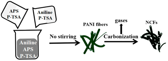
Figure 1.
The schematic diagram of the preparation of NCFs.
2.3. Material Characterization
The morphology of the samples was characterized using a scanning electron microscope (SEM, Hitachi S4800, Tokyo, Japan) and transmission electron microscope (TEM, Tecnai G2 F30, The Netherlands). The specific surface area and the analysis of porosity for the materials were characterized by N2 adsorption/desorption isotherms at 77 K with an ASAP 2010 instrument (Micromeritics, Norcross, GA, USA). The composition was characterized using fourier transform infrared spectroscopy (FTIR, Nicolet 6700, USA), X-ray diffraction (XRD, PANalytical X’ Pert Pro, The Netherlands), and X-ray photoelectron spectroscopy (XPS, Kratos AXIS Ultra DLD, Shimadzu, Japan).
2.4. Electrochemical Measurements
All electrochemical measurements were performed in a three-electrode setup: A titanium coated with slurry as the working electrode, a platinum foil as the counter electrode, and Hg/Hg2SO4 as the reference electrode. A solution containing 5 M H2SO4 served as the electrolyte at room temperature. Cyclic voltammograms (CV) and galvanostatic charge/discharge (GCD) were measured by an electrochemical workstation (CHI 660D). Working electrodes were prepared with the as-prepared materials, acetylene black, and PVDF (Polyvinylidene Fluoride) in a mass ration of 8:1:1. The resulting slurry was dropped evenly onto the titanium sheet substrate (1 cm × 1 cm), and dried at 70 °C in a vacuum oven overnight. The loading weight was controlled to be around 2 mg cm−2. Then, the dried finished electrode was immersed in 5 M H2SO4 solution to infiltrate the active compositions completely. Electrochemical impedance spectroscopy (EIS, Nyquist plots) was carried out in the three-electrode system at an open circuit potential over a frequency range from 0.01 Hz to 100 kHz with a 10 mV amplitude.
The capacitance values are calculated from cyclic voltammetry curves according to the following Equation (1):
where C is the gravimetric capacitance (F g−1), I is the current value of the CV curve, υ is the scan rate of the CV curve, m (g) is the mass loading of active material, and Vc − Va is the potential window.
The capacitance values were also calculated from galvanostatic charge-discharge curves according to the following Equation (2):
where C is the specific capacitance (F g−1), I is the current value of the GCD curves, dt is the time of the galvanostatic discharging, m (g) is the mass loading of active material, and Vc − Va is the potential window.
3. Results and Discussion
3.1. Polymerization and Carbonization
The SEM images of P-TSA doped PANI depict a predominantly fibrous morphology with diameters varying from 100 to 200 nm (Figure 2c,d). The formation of polyaniline in the chemical oxidation polymerization approach usually consists of three main steps: Chemical reaction, nucleation, and growth [43,44,45,46]. In this case, aniline and oxidant are consumed instantly in the formation of the primary fibers, and the secondary growth or overgrowth of primary fibers are, therefore, suppressed during polymerization. However, the rapid mixing polymerization method does not guarantee preparation of the homogeneous polyaniline nanofibers.
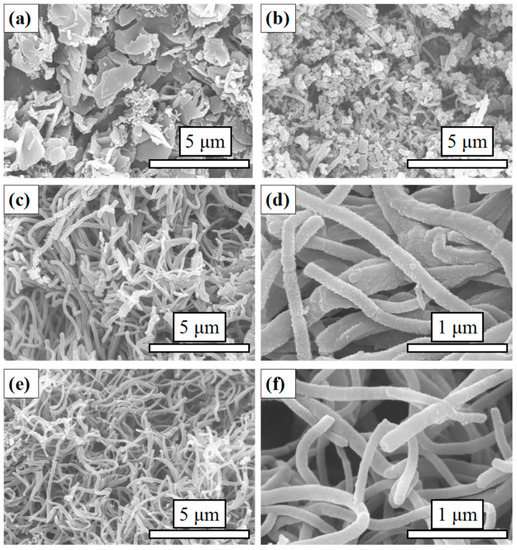
Figure 2.
SEM images of (a) DW, (b) SC, (c) and (d) PANI, (e) and (f) NCFs.
In this article, the organic sulfonic acid P-TSA, consisting of a hydrophilic SO3H group and a hydrophobic C6H4CH3 group, acts as a surfactant and protonating agent during the formation of PANI (Figure 3). To understand the effect of P-TSA on the morphology of polymerization products, we conducted a contrast experiment. The rapid mixing polymerization was carried out under the same operating conditions except the use of P-TSA and we obtained a dark green polyailine product named DW. The SEM image of DW shows micron and submicron lamellar structures with random orientations (Figure 2a). Obviously, P-TSA allows it to shred large agglomerates to form smaller polymer particles, and provides a significant improvement for the easy preparation of PANI nanofibers.
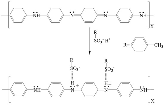
Figure 3.
The scheme of PANI doped with P-TSA.
The stirring condition also plays a key role in rapid mixing polymerization. In the other control group, the polymerization was performed under the same operating conditions with magnetic stirring. In this process, the solutions were rapidly mixed with vigorous stirring for 12 h. Similarly, the resulting product, named SC, had a dark green color under this operating condition. The SEM image of SC depicts very few nanofibers and a host of irregular particles (Figure 2b). These three products (PANI, DW, and SC) have the same appearance of a dark green color due to the same amounts of aniline and ammonium persulfate in their polymerization process.
As shown in Figure 1, NCFs were prepared by one-step carbonization of PANI at 700 °C for 2 h under N2 atmosphere. The morphology and structure of NCFs were characterized by scanning electron microscopy (SEM) and transmission electron microscopy (TEM). As shown in Figure 2c,d, the as-prepared carbonization product maintains the morphology of primary PANI fibers with some shrinkage, the surface is smoother than PANI fibers, and the length of carbon fibers derived from polyaniline is longer than that of previous reports [31,34]. To further determine the internal structure and porous texture, TEM images of NCFs are exhibited (Figure 4). Interestingly, both solid and hollow carbon fibers can be observed in the images (Figure 4a,b). As we know, the hollow architecture of the as-prepared NCFs may play an important role in increasing the effective utilization of active material and the cycling stability [16,31]. In addition, as shown in Figure 4c, the element mappings reveal that a uniform distribution of N and O elements on the surface of carbon fibers exists, which is in agreement with XPS analysis. It is noted that the yield of carbonized product is about 50 wt %. This is the first time that PANI nanofibers doped with P-TSA have been used as a precursor to prepare carbon materials with a high nitrogen content.
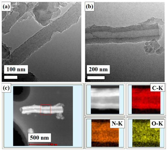
Figure 4.
TEM images of (a) and (b) NCFs; (c) element mappings of the designated square part of NCFs.
It also offers the possible development of a template-free, easy, synthetic method capable of producing bulk amounts of pure and uniform PANI nanotubes in the presence of P-TSA. According to the literature, the mechanism of formation of nanofiber structures involves the initial formation of self-assembled micelles of the P-TSA and aniline through hydrogen bonding and hydrophilic/hydrophobic interactions that can then act as templates for nanofiber growth. Since the oxidant (APS) is hydrophilic, the polymerization has to take place at the interface of water and the micelles [55]. A hypothesized reason for the morphology difference, such as solid and hollow carbon structures, is the aniline/P-TSA ratio. The synthesis, mechanism, and characterization of PANI nanotubes via the rapid mixing polymerization method in P-TSA solution will be investigated in our future work. Additionally, textural PANI-derived carbon materials’ properties, such as microporosity, could be properly tuned, resulting in a suitable proportion of micro- and mesoporosity by using different doping anions [33]. Thus, it is meaningful to study the effect of P-TSA on PANI-derived carbon and comparing it with other doped acids, such as other organic acids and polymer acids.
3.2. Physichemical Characteristics of Samples
As shown in Figure 5a, the characteristic peaks of PANI at 1572 cm−1 and 1494 cm−1 are assigned to the C=C stretching deformation mode of the quinoid and benzenoid rings, respectively. The C-N stretching vibration band at 1303 cm−1, C=N stretching vibration band at 1146 cm−1, and O=S=O stretching vibration band at 1034 cm−1 demonstrate that PANI doped with P-TSA has been successfully prepared in our study [51]. The red line presents the FT-IR spectrum of NCFs. The band at about 3421 cm−1 is attributed to the N-H stretching vibration, the C-N stretching vibration band and C=N stretching vibration band are still well observed. The spectrum of NCFs corresponds to the disordered carbon-like material with incorporated nitrogen in its structure [31,33].
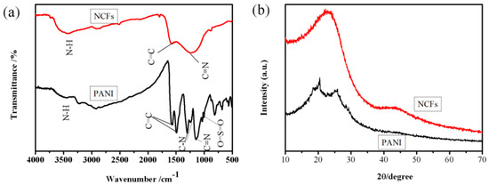
Figure 5.
(a) FT-IR spectra and (b) XRD patterns of samples.
The XRD of PANI and NCFs are given in Figure 5b. Two obviously broad peaks at about 2θ = 18°, 20°, and 25° have been ascribed to the (011), (020), and (200) faces of the polymer chain of PANI, respectively. The characteristic peaks at about 2θ = 18°, 20°, and 25° have been ascribed to π–π interchain stacking, the periodicity parallel and perpendicular to the polymer chains [41,49]. Generally, the dopant P-TSA and polymer undergo various interactions and organize the polymer chains in highly ordered arrangement. The XRD pattern of NCFs exhibit two broad diffraction peaks around 24° and 43°, which correspond to the (002) and (100) faces of hexagonal graphitic carbon, respectively [2,4,31]. The infrared and XRD spectra are similar to those of the carbon materials derived from PANI indicate that the carbonization at 700 °C for 2 h is suggested for the available conversion of PANI nanofibers to amorphous carbon-like materials.
Figure 6a confirms that the nitrogen adsorption-desorption isotherm of NCFs exhibits a mixture of type I isotherm in the low pressure region and type IV isotherm with an H3-typehysteresis loop in the high pressure region, demonstrating the co-existence of micropores and mesopores. This hysteresis loop is indicative of mesoporous adsorbent associated capillary condensation during adsorption–desorption [6]. The Brunauer-Emmett-Teller (BET) surface area, average pore size, and pore volume is 915 m2 g−1, 2.7 nm, and 0.61 cm3 g−1, respectively. Pore size distribution (inset Figure 6a) verifies that mesopores mainly centre in the region of 2–5 nm, which are more favorable for electrochemical performance [22].
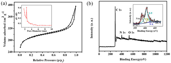
Figure 6.
(a) N2 adsorption/desorption isotherm of NCFs and inset pore-size distribution curve; (b) XPS survey spectrum of NCFs and inset N 1 s high resolution spectra.
As shown in Figure 6b, three X-ray photoelectron spectroscopy (XPS) peaks at a binding energy of 284.9, 400.7, and 532.8 eV correspond to C 1 s, N 1 s, and O 1 s, respectively. The XPS survey spectrum suggests that the nitrogen content and oxygen content are 7.59 at % and 4.98 at %, respectively. The N 1 s high resolution spectrum can be assigned to four peaks: Pyridinic N (N-6), pyrrolic N (N-5), quaternary N (N-Q), and pyridine-N-oxide (N-X) (inset Figure 6b). As shown in Figure 7, the chemical forms of N in nitrogen doped carbon materials have been proposed by research groups [1,2,3,4,5,6,7,8,9,10,11,12,13,14]. N-Q can offer highly active sites, and N-6 and N-5 can improve the wettability of carbon material to increase the effective specific surface area for double layer formation. N-6 and N-5 are prone to offer the following reversible redox reactions that could be taking place on the nitrogen-doped carbon surface in aqueous medium [9,10,11,12,13]:
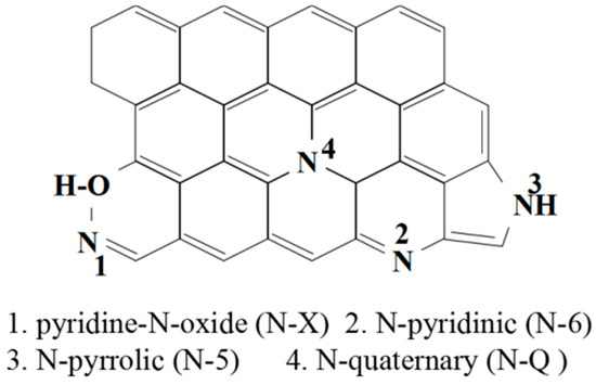
Figure 7.
The chemical forms of N in nitrogen-doped carbon materials.
>C represents the carbon network, thus, offering excellent pseudo-capacitance for the supercapacitor. N-X and N-Q provide outstanding capacitance retention, meanwhile the existence of N-Q enhances the electron transfer and the electrical conductivity of materials and, hence, improves the capacitance performance.
The significant amount of surface oxygen content can be ascribed to chemisorbed oxygen or water during the preparation of NCFs. In addition, a moderate amount of oxygen-containing functional groups can improve the wettability and increase the specific capacitance of carbon materials as well. The following are possible reactions on the oxygen-doped carbon surface in aqueous medium [56]:
>C represents the carbon network. To the best of our knowledge, the nitrogen-and oxygen-codoped carbon materials exhibit a high specific capacitance and exceptional long-term electrochemical stability [56].
3.3. Electrochemical Study
This is the first time that PANI nanofibers doped with P-TSA are used as a precursor to prepare carbon materials. We realized the initial ideas of using nanostructured PANI as a precursor to obtain nitrogen-doped carbons materials with high nitrogen content and a high specific surface area, and removing activation at high temperatures. Subsequently, capacitive properties of NCFs are characterized by electrochemical analysis with a three-electrode test cell.
The cyclic voltammograms (CV) of NCFs with different scanning rates, as seen in Figure 8a, show nearly square cycle profiles without any obvious redox peaks at a potential window ranging from 0 V to −0.8 V vs Hg/Hg2SO4, indicating that typical double layer capacitance is present [27]. The shape of CV curves is very consistent with the previous report [27,29], depicting that the CV curves of NCFs demonstrate moderate distortion, which can be attributed to the faradic reactions of nitrogen-and oxygen-containing functional groups on the carbon’s surface [29]. The functional groups of carbon materials generate a fast and reversible faradaic redox reaction between the ions of electrolytes and the carbon electrode surface mentioned above. The specific capacitances of NCFs calculated from the CV profiles are 172, 167, 147, 139, and 105 F g−1 at 2, 5, 10, 20, and 50 mV s−1, respectively. It is a common behavior that the specific capacitance decreases from 172 F g−1 to 105 F g−1 with an increase in the scan rate from 2 mV s−1 to 50 mV s−1 due to the decreasing ability of ionic penetration into micropores, which is a widely accepted explanation of this behavior [32]. In the present work, at a relatively low scan rate of 50 mV s−1, the shape of the CV curve already shows a transition from box-like to spindle, indicating sluggish ionic diffusion has occurred. To understand the ionic diffusion clearly, we characterize the kinetic analysis of the NCFs electrode. Figure 8b is a plot of the specific capacitance vs scan rate−1/2 and it does not seem to follow a linear trend, starting from 2 mV s−1 to 50 mV s−1. At the low scan rate, the capacitance is almost independent of the scan rate, indicating that the electrolyte diffusion is not the limiting factor for charge storage owing to the special structure and heteroatoms functional groups of NCFs [57]. NCFs exhibits a 71.4% capacitance retention with the increasing scan rate from 10 mV s−1 to 50 mV s−1, which is comparable to others [29].
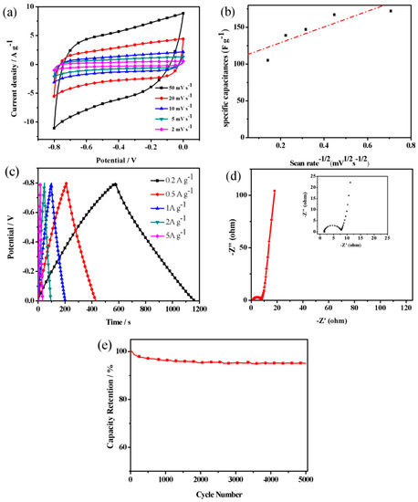
Figure 8.
(a) CV curves at different scan rates; (b) a plot of specific capacitance vs scan rate−1/2; (c) GCD curves at different current densities; (d) Nyquist plots of NCFs’ electrodes in the frequency range of 0.01 Hz–100 kHz; and (e) cycling performance of NCFs electrode.
The curves of the galvanostatic charge/discharge (GCD) exhibit a precise symmetry, suggesting a prominent capacitive behavior of the electrode (Figure 8c). The specific capacitances of NCFs calculated from the GCD profiles are 182, 162, 139, 128, and 115 F g−1 at 0.2, 0.5, 1, 2, and 5 A g−1, respectively. With the increasing current densities from 0.5 A g−1 to 10 A g−1, the capacitance decreases only by 30%. Figure 8d shows the Nyquist plots of NCFs’ electrodes in the frequency range of 0.01 Hz–100 kHz. For pseudocapacitive materials, the Nyquist representation will contain a vertical line with a phase angle of 90° or less and a semicircle in the high-frequency region associated with the charge-transfer resistance [58]. Compared to the literature [35], a small semicircle is observed at the high frequency region for NCFs, meaning the smaller charges transfer resistance. Obviously, NCFs exhibit a steep line with a higher slope in the low-frequency region, indicating a better capacitive performance. Satisfyingly, NCFs have excellent cycling stability (89% capacitance retention over 5000 cycles at current density of 5 A g−1), as shown in Figure 8e.
The comparison of previously reported carbon materials for supercapacitor electrodes in terms of electrochemical capacitive performance is also described in Table 1. Obviously, the specific capacitance of NCFs exhibits a comparable capacitance value with the reported results.

Table 1.
Comparison of specific capacitance values with recent reported literature in a three-electrode cell system.
4. Conclusions
In summary, we firstly develop a facile and fast approach for the synthesis of PANI nanofibers by rapid mixing polymerization with the use of P-TSA as a dopant. Subsequently, novel NCFs are obtained by one-step carbonization of PANI nanofibers precursor. The as-prepared NCFs with diameters of 100–150 nm possess a high specific surface area and enriched heteroatoms. The result of the electrochemical measurements shows that NCFs have typical double layer capacitive behavior, with the highest specific capacitance of 182 F g−1, and an acceptable capacitance loss is observed after 5000 cycles at 5 A g−1. The results demonstrate that NCFs have good capacitive properties, meanwhile the route of production of nitrogen-doped carbon nanofibers has features of being simple, having good repeatability, and are easy to be operated.
Author Contributions
Conceptualization, Y.G.; Investigation, J.Y.; Resources, X.X.; Software, X.X. and L.C.; Writing—original draft, J.Y.; Writing—review & editing, J.Y.
Funding
National Key Research and Development Program of China (2016YFC0305004).
Conflicts of Interest
The authors declare no conflict of interest.
References
- Yazdi, A.A.; D’Angelo, L.; Omer, N.; Windiasti, G.; Lu, X.; Xu, J. Carbon nanotube modification of microbial fuel cell electrodes. Biosens. Bioelectron. 2016, 85, 536–552. [Google Scholar] [CrossRef] [PubMed]
- Tseng, C.A.; Lee, C.P.; Huang, Y.J.; Pang, H.W.; Ho, K.C.; Chen, Y.T. One-step synthesis of graphene hollow nanoballs with various nitrogen-doped states for electrocatalysis in dye-sensitized solar cells. Mater. Today Energy 2018, 8, 15–21. [Google Scholar] [CrossRef]
- Li, J.G.; Zhang, F.; Wang, C.D.; Shao, C.Z.; Li, B.Z.; Li, Y.; Wu, Q.H.; Yang, T.G. Self nitrogen-doped carbon nanotubes as anode materials for high capacity and cycling stability lithium-ion batteries. Mater. Des. 2017, 133, 169–175. [Google Scholar] [CrossRef]
- Kagenda, C.; Lule, I.; Paulik, C. Nitrogen-doped carbon materials for high performing lithium air batteries. S. Afr. J. Chem. Eng. 2018, 25, 32–41. [Google Scholar] [CrossRef]
- Zhang, C.L.; Wang, B.W.; Shen, X.C.; Liu, J.W.; Kong, X.K.; Chuang, S.; Yang, D.; Dong, A.; Peng, Z.M. A nitrogen-doped ordered mesoporous carbon/graphene framework as bifunctional electrocatalyst for oxygen reduction and evolution reactions. Nano Energy 2016, 30, 503–510. [Google Scholar] [CrossRef]
- Marrakchi, F.; Auta, M.; Khanday, W.A.; Hameed, B.H. High-surface-area and nitrogen-rich mesoporous carbon material from fishery waste for effective adsorption of methylene blue. Powder Technol. 2017, 321, 428–434. [Google Scholar] [CrossRef]
- Zeng, F.Y.; Sui, Z.Y.; Liu, S.; Liang, H.P.; Zhan, H.H.; Han, B.H. Nitrogen-doped carbon aerogels with high surface area for supercapacitors and gas adsorption. Mater. Today Commun. 2018, 1, 1–7. [Google Scholar] [CrossRef]
- Lota, G.; Grzyb, B.; Machnikowsk, H.; Machnikowski, J.; Frackowiak, E. Effect of nitrogen in carbon electrode on the supercapacitor performance. Chem. Phys. Lett. 2005, 404, 53–58. [Google Scholar] [CrossRef]
- Inagaki, M.; Toyoda, M.; Soneda, Y.; Morishita, T. Nitrogen-doped carbon materials. Carbon 2018, 132, 104–140. [Google Scholar] [CrossRef]
- Lota, G.; Lota, K.; Frackowiak, E. Nanotubes based composites rich in nitrogen for supercapacitor application. Electrochem. Commun. 2007, 9, 1828–1832. [Google Scholar] [CrossRef]
- Yun, Y.S.; Park, H.H.; Jin, H.J. Pseudocapacitive Effects of N-Doped Carbon Nanotube Electrodes in Supercapacitors. Materials 2012, 5, 1258–1266. [Google Scholar] [CrossRef]
- John, A.R.; Arumugam, P. Open ended nitrogen-doped carbon nanotubes for the electrochemical storage of energy in a supercapacitor electrode. J. Power Sources 2015, 277, 387–392. [Google Scholar] [CrossRef]
- Garcia, B.B.; Candelaria, S.L.; Cao, G. Nitrogenated porous carbon electrodes for supercapacitor. J. Mater. Sci. 2012, 47, 5996–6004. [Google Scholar] [CrossRef]
- Huang, K.; Li, M.; Chen, Z.H.; Yao, Y.Y.; Yang, X.W. Nitrogen-enriched porous carbon nanofiber networks for binder-free supercapacitors obtained by using a reactive surfactant as a porogen. Electrochim. Acta 2015, 158, 306–313. [Google Scholar] [CrossRef]
- Yang, W.; Ni, M.; Ren, X.; Tian, Y.F.; Li, N.; Su, Y.F.; Zhang, X.L. Graphene in Supercapacitor Applications. Curr. Opin. Colloid Interface Sci. 2015, 20, 416–428. [Google Scholar] [CrossRef]
- Hossain, A.; Bandyopadhyay, P.; Guin, P.S.; Roy, S. Recent developed different structural nanomaterials and their performance for supercapacitor application. Appl. Mater. Today 2017, 9, 300–313. [Google Scholar] [CrossRef]
- Han, Y.; Ge, Y.; Chao, Y.F.; Wang, C.Y.; Wallace, G.G. Recent progress in 2D materials for flexible supercapacitors. J. Energy Chem. 2018, 27, 57–72. [Google Scholar] [CrossRef]
- Kötz, R.; Carlen, M. Principles and applications of electrochemical capacitors. Electrochim. Acta 2000, 45, 2483–2498. [Google Scholar] [CrossRef]
- Frackowiak, E.; Beguin, F. Carbon materials for the electrochemical storage of energy in capacitors. Carbon 2001, 39, 937–950. [Google Scholar] [CrossRef]
- Pandolfo, A.G.; Hollenkamp, A.F. Carbon properties and their role in supercapacitors. J. Power Sources 2006, 157, 11–27. [Google Scholar] [CrossRef]
- Frackowiak, E. Carbon materials for supercapacitor application. Phys. Chem. Chem. Phys. 2007, 9, 1774–1785. [Google Scholar] [CrossRef] [PubMed]
- Wang, G.P.; Zhang, L.; Zhang, J.J. A review of electrode materials for electrochemical supercapacitors. Chem. Soc. Rev. 2012, 41, 797–828. [Google Scholar] [CrossRef] [PubMed]
- Gordana, C.M.; Igor, P.; Slavko, M. One-dimensional nitrogen-containing carbon nanostructures. Prog. Mater. Sci. 2015, 69, 61–182. [Google Scholar]
- Shen, W.Z.; Zhang, S.C.; He, Y.; Li, J.F.; Fan, W.B. Hierarchical porous polyacrylonitrile-based activated carbon fibers for CO2 capture. J. Mater. Chem. 2011, 21, 14–36. [Google Scholar] [CrossRef]
- Wu, X.Z.; Zhou, J.; Xing, W.; Zhang, Y.; Bai, P.; Xu, B.J.; Zhuo, S.P.; Xue, Q.Z.; Yan, Z.F. Insight into high areal capacitances of low apparent surface area carbons derived from nitrogen-rich polymers. Carbon 2015, 94, 560–567. [Google Scholar] [CrossRef]
- Maetz, A.; Delmotte, L.; Moussa, G.; Dentzer, J.; Knopf, S.; Ghimbeu, C.M. Facile and sustainable synthesis of nitrogen-doped polymer and carbon porous spheres. Green Chem. 2017, 19, 2266–2274. [Google Scholar] [CrossRef]
- Zhang, J.L.; Zhang, W.F.; Han, M.F.; Pang, J.; Xiang, Y.; Cao, G.P.; Yang, Y.S. Synthesis of nitrogen-doped polymeric resin-derived porous carbon for high performance supercapacitors. Microporous Mesoporous Mater. 2018, 270, 204–210. [Google Scholar] [CrossRef]
- Eftekhar, A.; Li, L.; Yang, Y. Polyaniline supercapacitors. J. Power Sources 2017, 347, 86–107. [Google Scholar] [CrossRef]
- Li, L.M.; Liu, E.H.; Li, J.; Yang, Y.J.; Shen, H.J.; Huang, Z.Z.; Xiang, X.X.; Li, W. A doped activated carbon prepared from polyaniline for high performance supercapacitors. J. Power Sources 2010, 195, 1516–1521. [Google Scholar] [CrossRef]
- Yang, M.M.; Cheng, B.; Song, H.H.; Chen, X.H. Preparation and electrochemical performance of polyaniline-based carbon nanotubes as electrode material for supercapacitor. Electrochim. Acta 2010, 55, 7021–7027. [Google Scholar] [CrossRef]
- Yuan, D.S.; Zhou, T.X.; Zhou, S.L.; Zou, W.J.; Mo, S.S.; Xia, N.N. Nitrogen-enriched carbon nanowires from the direct carbonization of polyaniline nanowires and its electrochemical properties. Electrochem. Commun. 2011, 13, 242–246. [Google Scholar] [CrossRef]
- Han, J.P.; Xu, G.Y.; Ding, B.; Pan, J.; Dou, H.; MacFarlane, D.R. Porous nitrogen-doped hollow carbon spheres derived from polyaniline for high performance supercapacitors. J. Mater. Chem. A 2014, 2, 5352–5357. [Google Scholar] [CrossRef]
- Zornitta, R.L.; García-Mateos, F.J.; Lado, J.J.; Rodríguez-Mirasol, J.; Cordero, T.; Hammer, P.; Ruotolo, L.A.M. High-performance activated carbon from polyaniline for capacitive deionization. Carbon 2017, 123, 318–333. [Google Scholar] [CrossRef]
- Wang, G.Q.; Yan, C.; Hou, S.; Zhang, W. Low-cost counter electrodes based on nitrogen-doped porous carbon nanorods for dye-sensitized solar cells. Mater. Sci. Semicond. Process. 2017, 63, 190–195. [Google Scholar] [CrossRef]
- Gao, B.F.; Zhou, H.T.; Yang, J.H. One-step preparation of nitrogen-doped graphene nanosheets forhigh-performance supercapacitors. Appl. Surf. Sci. 2017, 409, 350–357. [Google Scholar] [CrossRef]
- Bober, P.; Trchová, M.; Morávková, Z.; Kovářová, J.; Vulić, J.; Gavrilov, N.; Pašti, I.A.; Stejskal, J. Phosphorus and nitrogen-containing carbons obtained by the carbonization of conducting polyaniline complex with phosphites. Electrochim. Acta 2017, 246, 443–450. [Google Scholar] [CrossRef]
- Kumar, R.; Yadav, B.C. Humidity sensing investigation on nanostructured polyaniline synthesized via chemical polymerization method. Mater. Lett. 2016, 167, 300–302. [Google Scholar] [CrossRef]
- Mi, H.Y.; Zhang, X.G.; Yang, S.D.; Ye, X.G.; Luo, J.M. Polyaniline nanofibers as the electrode material for supercapacitors. Mater. Chem. Phys. 2008, 112, 127–131. [Google Scholar] [CrossRef]
- Wang, T.Q.; Zhong, W.B.; Ning, X.T.; Wang, Y.X.; Yang, W.T. Facile synthesis of polyaniline “sunflowers” with arrays of oriented nanorods. J. Colloid Interface Sci. 2009, 334, 108–112. [Google Scholar] [CrossRef] [PubMed]
- Li, R.Q.; Chen, Z.; Li, J.Q.; Zhang, C.H.; Guo, Q. Effective synthesis to control the growth of polyaniline nanofibers by interfacial polymerization. Synth. Met. 2013, 171, 39–44. [Google Scholar] [CrossRef]
- Jaymand, M. Recent progress in chemical modification of polyaniline. Prog. Polym. Sci. 2013, 38, 1287–1306. [Google Scholar] [CrossRef]
- Tariq, S.N.; Ali, J.S. Polyaniline nanofibers and nanocomposites: Preparation, characterization, and application for Cr(VI) and phosphate ions removal from aqueous solution. Arab. J. Chem. 2017, 10, 3459–3467. [Google Scholar]
- Lu, X.W.; Wu, W.; Chen, J.F.; Zhang, P.Y.; Zhao, Y.B. Preparation of polyaniline nanofibers by high gravity chemical oxidative polymerization. Ind. Eng. Chem. Res. 2011, 50, 5589–5595. [Google Scholar] [CrossRef]
- Ramana, G.V.; Pandya, B.; Srikanth, V.S.S.; Jain, P.K. Rapid mixing chemical oxidative polymerization: An easy route to prepare PANI coated small-diameter CNTs/PANI nanofibres composite thin film. Mater. Sci. 2014, 37, 585–588. [Google Scholar]
- Zakaria, Z.; Halim, N.F.A.; Schleusingen, M.H.V.; Islam, A.K.M.S.; Hashim, U.; Ahmad, M.N. Effect of hydrochloric acid concentration on morphology of polyaniline nanofibers synthesized by rapid mixing polymerization. J. Nanomater. 2015, 2015, 218204. [Google Scholar] [CrossRef]
- Deng, J.X.; Guo, J.S.; Liu, P. Growth of polyaniline nanomaterials in rapid-mixing polymerization. Colloid Surf. A Physicochem. Eng. 2017, 521, 247–250. [Google Scholar] [CrossRef]
- Ayad, M.M.; Zaki, E.A. Doping of polyaniline films with organic sulfonic acids in aqueous media and the effect of water on these doped films. Eur. Polym. J. 2008, 44, 3741–3747. [Google Scholar] [CrossRef]
- Park, H.W.; Kim, T.; Huh, J.Y.; Kang, M.J.; Lee, J.E.; Yoon, H. Anisotropic growth control of polyaniline nanostructures and their morphology-dependent electrochemical characteristics. Amer. Chem. Soc. 2012, 6, 7624–7633. [Google Scholar] [CrossRef] [PubMed]
- Mahmood, I.; Ahmad, I.; Liu, H.Z.; Guo Chen, G. A new strategy for the synthesis of polyaniline nanostructures using m-CPBA as an oxidant. J. Mater. Sci. Mater. Electron. 2013, 24, 1181–1186. [Google Scholar] [CrossRef]
- Chutia, P.; Nath, C.; Kumar, A. Dopant size dependent variable range hopping conduction in polyaniline nanorods. Appl. Phys. A 2014, 115, 943–951. [Google Scholar] [CrossRef]
- Bhadra, J.; Madi, N.K.; Al-Thani, N.J.; Al-Maadeed, M.A. Polyaniline/polyvinyl alcohol blends: Effect of sulfonic acid dopantson microstructural, optical, thermal and electrical properties. Synth. Met. 2014, 191, 126–134. [Google Scholar] [CrossRef]
- Mu, J.J.; Ma, G.F.; Peng, H.; Li, J.J.; Sun, K.J.; Lei, Z.Q. Facile fabrication of self-assembled polyaniline nanotubes doped with D-tartaric acid for high-performance supercapacitors. J. Power Sources 2013, 242, 797–802. [Google Scholar] [CrossRef]
- Xu, G.C.; Wang, W.; Qu, W.F.; Yin, Y.S.; Chu, L.; He, B.L.; Wu, H.K.; Fang, J.R.; Bao, Y.S.; Liang, L. Electrochemical properties of polyaniline in p-toluene sulfonic acid solution. Eur. Polym. J. 2009, 45, 2701–2707. [Google Scholar] [CrossRef]
- Rozlívková, Z.; Trchová, M.; Exnerová, M.; Stejskal, J. The carbonization of granular polyaniline to produce nitrogen-containing carbon. Synth. Met. 2011, 161, 1122–1129. [Google Scholar] [CrossRef]
- Zhang, L.J.; Peng, H.; Sui, J.; Kilmartin, P.A.; Jadranka, T.S. Polyaniline nanotubes doped with polymeric acids. Curr. Appl. Phys. 2008, 8, 312–315. [Google Scholar] [CrossRef]
- Ye, Z.Q.; Wang, F.J.; Jia, C.; Mu, K.G.; Yu, M.; Lv, Y.Y.; Shao, Z.Q. Nitrogen and oxygen-codoped carbon nanospheres for excellent specific capacitance and cyclic stability supercapacitor electrodes. Chem. Eng. J. 2017, 330, 1166–1173. [Google Scholar] [CrossRef]
- Pan, Q.; Shim, E.; Pourdeyhimi, B.; Gao, W. Nylon-Graphene Composite Nonwovens as Monolithic Conductive or Capacitive Fabrics. ACS Appl. Mater. Interfaces 2017, 9, 8308–8316. [Google Scholar] [CrossRef] [PubMed]
- Augustyn, V.; Simon, P.; Dunn, B. Pseudocapacitive oxide materials for high-rate electrochemical energy storage. Energy. Environ. Sci. 2014, 75, 1597–1614. [Google Scholar] [CrossRef]
- Xin, G.X.; Wang, Y.H.; Jia, S.P.; Tian, P.F.; Zhou, S.Y.; Zang, J.B. Synthesis of nitrogen-doped mesoporous carbon from polyaniline with an F127 template for high-performance supercapacitors. Appl. Surf. Sci. 2017, 422, 654–660. [Google Scholar] [CrossRef]
- Yi, J.N.; Qing, Y.; Wu, C.T.; Zeng, Y.X.; Wu, Y.Q.; Lu, X.H.; Tong, Y.X. Lignocellulose-derived porous phosphorus-doped carbon as advanced electrode for supercapacitors. J. Power Sources 2017, 351, 130–137. [Google Scholar] [CrossRef]
- Guo, S.N.; Shen, H.K.; Tie, Z.F.; Peng, S.Z.; Shi, H.; Fan, J.C.; Xu, Q.J.; Min, Y.L. Three-dimensional cross-linked Polyaniline fiber/N-doped porous carbon with enhanced electrochemical performance for highperformance supercapacitor. J. Power Sources 2017, 359, 285–294. [Google Scholar] [CrossRef]
- Yu, S.; Liu, D.; Zhao, S.Y.; Bao, B.F.; Jin, C.D.; Huang, W.J.; Hao Chen, H.; Shen, Z.H. Synthesis of wood derived nitrogen-doped porous carbon–polyaniline composites for supercapacitor electrode materials. RSC Adv. 2015, 5, 30943–30949. [Google Scholar] [CrossRef]
© 2018 by the authors. Licensee MDPI, Basel, Switzerland. This article is an open access article distributed under the terms and conditions of the Creative Commons Attribution (CC BY) license (http://creativecommons.org/licenses/by/4.0/).