Doppler-Based Acoustic Gyrator


Laboratory of Wave Engineering, École Polytechnique Fédérale de Lausanne (EPFL), 1015 Lausanne, Switzerland
*
Author to whom correspondence should be addressed.
Appl. Sci. 2018, 8(7), 1083; https://doi.org/10.3390/app8071083
Submission received: 30 May 2018
/
Revised: 27 June 2018
/
Accepted: 2 July 2018
/
Published: 3 July 2018
(This article belongs to the Special Issue Acoustic Metamaterials)
Abstract
:Non-reciprocal phase shifters have been attracting a great deal of attention due to their important applications in filtering, isolation, modulation, and mode locking. Here, we demonstrate a non-reciprocal acoustic phase shifter using a simple acoustic waveguide. We show, both analytically and numerically, that when the fluid within the waveguide is biased by a time-independent velocity, the sound waves travelling in forward and backward directions experience different amounts of phase shifts. We further show that the differential phase shift between the forward and backward waves can be conveniently adjusted by changing the imparted bias velocity. Setting the corresponding differential phase shift to 180 degrees, we then realize an acoustic gyrator, which is of paramount importance not only for the network realization of two port components, but also as the building block for the construction of different non-reciprocal devices like isolators and circulators.
1. Introduction
Microwave phase shifters are two-port components that provide an arbitrary and variable transmission phase angle with low insertion loss [1,2,3]. Since their discovery in the 19th century, such phase shifters have found important applications in devices such as phased array antennas and receivers [4,5], beam forming and steering networks [6,7], measurement and testing systems [8,9], filters [10,11], modulators [12,13], frequency up-convertors [14], power flow controllers [15], interferometers [16], and mode lockers [17].
Various types of microwave phase shifters have been proposed and demonstrated over years, all of which can be fundamentally categorized into two groups: reciprocal and non-reciprocal phase shifters. Non-reciprocal phase shifters providing different phase shift for forward and backward waves, however, are of more importance especially when it comes to the realization of devices like gyrators [18], isolators [19], and circulators [20], being critical for radar systems and networks.
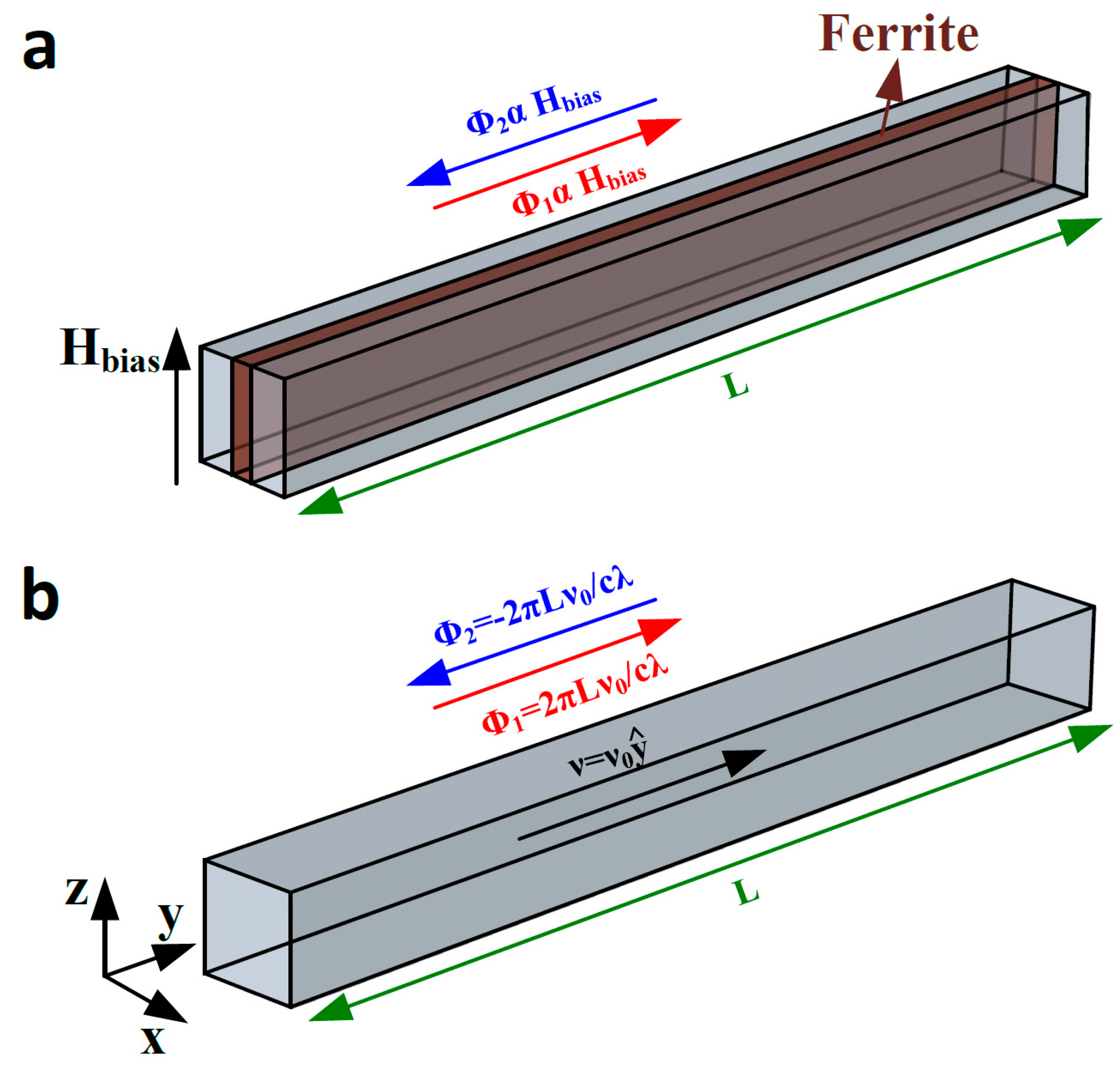
In its most traditional form, a non-reciprocal microwave phase shifter is composed of a rectangular waveguide partially filled with a ferrite slab submitted to a magneto-static bias field [1] (see Figure 1a). When the bias field is zero, the ferrite is demagnetized and the structure provides a reciprocal phase shift of for instance, being proportional to the length of the waveguide, for both forward and backward propagation. However, when the bias field is increased from zero, the ferrite slab starts magnetizing, giving rise to distinct and continuously variable phase shifts of and for forward and backward waves, respectively.
In contrast to electromagnetism, realizing a non-reciprocal phase shifter in acoustics is challenging as sound waves only weakly interact with magnetic fields [21,22,23,24,25,26,27,28,29]. Recently, proposals to break the conventional wisdom of sound reciprocity have been reported, of which most rely on non-linear mechanisms [30,31,32,33]. Despite their applicability, these nonlinear structures accompany with unwanted features such as high-power consumption and geometrical bulky configuration, reducing their practical worth.
A recent breakthrough, however, has opened exciting venues to break the reciprocity of acoustic waves in fully linear manners. In [22], it was shown that applying a time-independent bias velocity to stationary fluids allows one to strongly break the time reversal symmetry and to induce acoustic non-reciprocity. This salient feature was then leveraged to demonstrate a subwavelength circulator in airborne acoustics, allowing audible sound to be coupled to a certain port, while isolating transmission in another.
On the basis of this idea, here we first demonstrate a fully linear non-reciprocal acoustic phase shifter. This is achieved in a simple acoustic waveguide that is filled with air on which a constant bias velocity is applied. Through analytical analysis and numerical simulations, we show how the proposed structure provides different phase shifts for forward and backward transmission. We further show that the associated differential phase shift can be simply tuned by changing the bias velocity. By setting a fluid bias velocity that corresponds to a differential phase shift of 180 degrees, we then implement an acoustic gyrator, which is an important two port component serving as the building block for a large variety of non-reciprocal acoustic devices such as isolators and circulators. We believe that our finding opens up exciting frontiers in the field of modern acoustic engineering [34,35,36,37,38,39,40,41,42,43,44,45,46,47,48,49,50,51,52,53,54,55,56,57,58,59,60,61,62,63,64,65,66,67] for the design and realization of various innovative components, such as phase modulators, beam forming devices, switches, and frequency convertors.
2. Acoustic Phase Shifter
In this section, we focus our attention on realizing a non-reciprocal acoustic phase shifter that brings about different phase shifts for forward and backward waves. As a starting point, consider the geometry represented in Figure 1b consisting of an acoustic waveguide filled with air on which a velocity of is assumed to be imparted. The overall length of the waveguide is supposed to be , where λ is the wavelength of the operation. When the fluid inside the waveguide is stationary, i.e., when , the signals travelling from the left to the right side of the waveguide acquire an overall phase shift of zero, as the waveguide length is a multiple of the wavelength. Similarly, sound waves injected into the right side of the waveguide are subject to an effective phase shift of zero when reaching the left side, which is consistent with the reciprocity of the device. When assuming a non-zero bias velocity motion (), however, the frequency of the signals propagating from the left to the right is Doppler shifted by an amount of . Consequently, they obtain an additional phase shift of (c is the speed of sound in the air) during their propagation (the red arrow in the figure). Figure 2a (the red line) illustrates the variation of versus the fluid velocity . The figure reveals that by changing the bias velocity, one can readily tune the overall phase shift that a signal obtains when passing through the waveguide. However, this is not something special by itself, as the same effect could be achieved by changing the length of the waveguide. The salient feature of the proposed structure becomes clear when we look at the propagation of the waves that travel in the opposite direction. In contrast to the previous case, the frequency of these types of signals is upshifted by an amount of with respect to the static frequency . The corresponding Doppler phase shift is therefore in this case, which is negative of Figure 2a (the blue line) plots the dependence of on the fluid motion velocity . It is evident that the motion of the fluid within the waveguide results in different phase shifts for forward and backward sound waves, making the structure non-reciprocal in phase. Notably, it was not possible to achieve such non-reciprocal behavior by solely changing the length of the waveguide. We further note that since there is no geometrical detour causing reflection or refraction, and since the amount of sound attenuation is quite low at the frequency of operation, the amplitude of the transmitted signals maintains almost the same value, regardless of the propagation direction. One can therefore express the scattering matrix of the waveguide as:
Note that the scattering matrix of the waveguide is unitary since we neglected the losses. In order to verify the scattering matrix of the above equation, we perform numerical simulations using the aeroacoustics module of Comsol Multiphysics, which is a full-wave solver working based on finite element method (FEM). In our numerical simulations, we surround the waveguide by sound hard wall boundary conditions, and terminate it at plane wave scattering boundary conditions inducing the excitation. We further assume the material filling the waveguide to be air with a density of and the bulk modulus of . Note that the choice of the filling medium is only for the sake of simplicity. We further remark that in the following, we neglect the Poiseuille flow originated from non-slippery walls, as our simulations show that its effect is indeed negligible. To measure the scattering parameters of the structure, we excite the waveguide from one end with a plane-wave sound field of unit amplitude and measure the phase of the signal receiving at the other end. Figure 2b shows the phase of the corresponding scattering parameters as a function of the fluid velocity. The results of this figure show a perfect agreement with those of Figure 2a, which were obtained by a simple argument based on Doppler shifts.
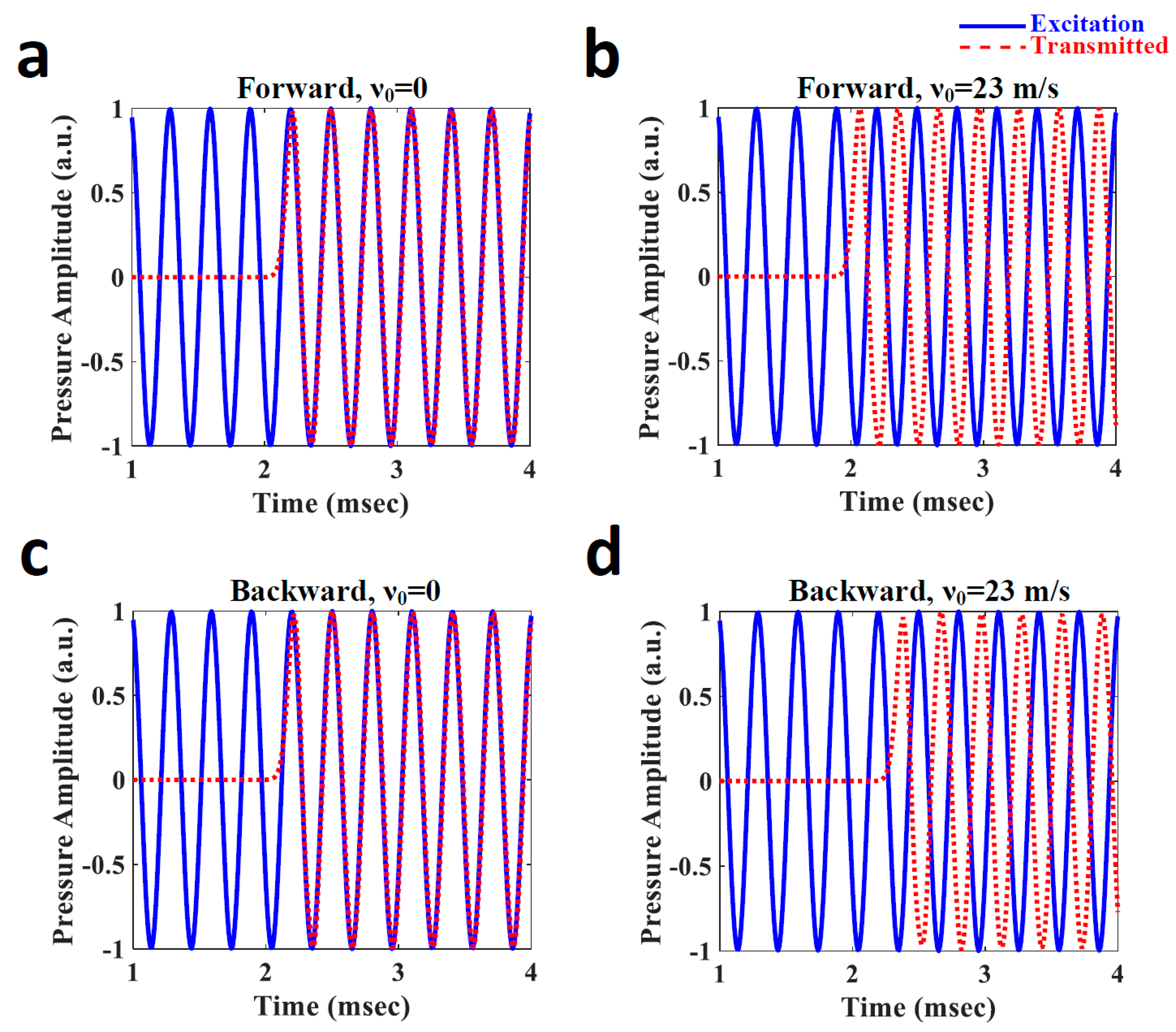
To further assess the non-reciprocal behavior of the proposed device, we perform finite difference time domain (FDTD) simulation with a time step of . The insets of Figure 3a represent the excitation (solid blue line) and the transmitted (dashed red line) signals when the waveguide is excited from the left side and when a stationary fluid motion is considered (). As observed, the injected signal is received after a time delay of . However, the received signal is still in phase with the excitation since the waveguide is multiple-wavelengths long. Now assume we impart a bias velocity of to the fluid within the waveguide, corresponding to an additional Doppler phase shift of 180 degrees. Figure 3b represents the time profiles of the excitation and transmitted fields. As expected, the transmitted signal is led by 180 degrees with respect to the excitation. The promising feature of the device, however, relies not on this phase shift, but on the non-reciprocal phase shift that it provides for the backward propagation. Hence, we repeat our analysis when the waveguide is excited from the other side. Figure 3c,d depict the temporal evolution of the corresponding excitation and transmitted signals in the cases of and , respectively. We notice that, when , the transmitted field had exactly the same time profile as that of Figure 3a. It is because of the fact that, as previously explained, the structure is reciprocal for the stationary fluid velocity. When , however, the transmitted field is lagged (not led) by 180 degrees with respect to the excitation, clearly confirming the non-reciprocity of the structure. Such simple non-reciprocal phase shifters can be utilized as the building blocks for the synthesis of more complex non-reciprocal devices such as gyrators, isolators, and circulators, among which the realization of the gyrator is discussed in detail in the following section.
3. Acoustic Gyrator
This section describes how an acoustic gyrator can be implemented making use of the non-reciprocal phase shifter that was demonstrated in the previous section. A gyrator is a fully passive, lossless two port device. Over the past decades, gyrators have been utilized not only for the network realization of two port components, but also as the building blocks of microwave filters, isolators, impedance converters, and equalizers [1]. The scattering matrix of an ideal gyrator is of the form
which means that a gyrator transmits forward waves without any phase shift, whereas it shifts the phase of backward waves by 180 degrees. Suppose now that the velocity of the fluid filling the waveguide of Figure 1a is chosen such that it corresponds to a phase shift of 90 degrees for forward, but that of −90 degrees for backward propagation (Figure 4a). The scattering matrix of the resulting phase shifter then reduces to
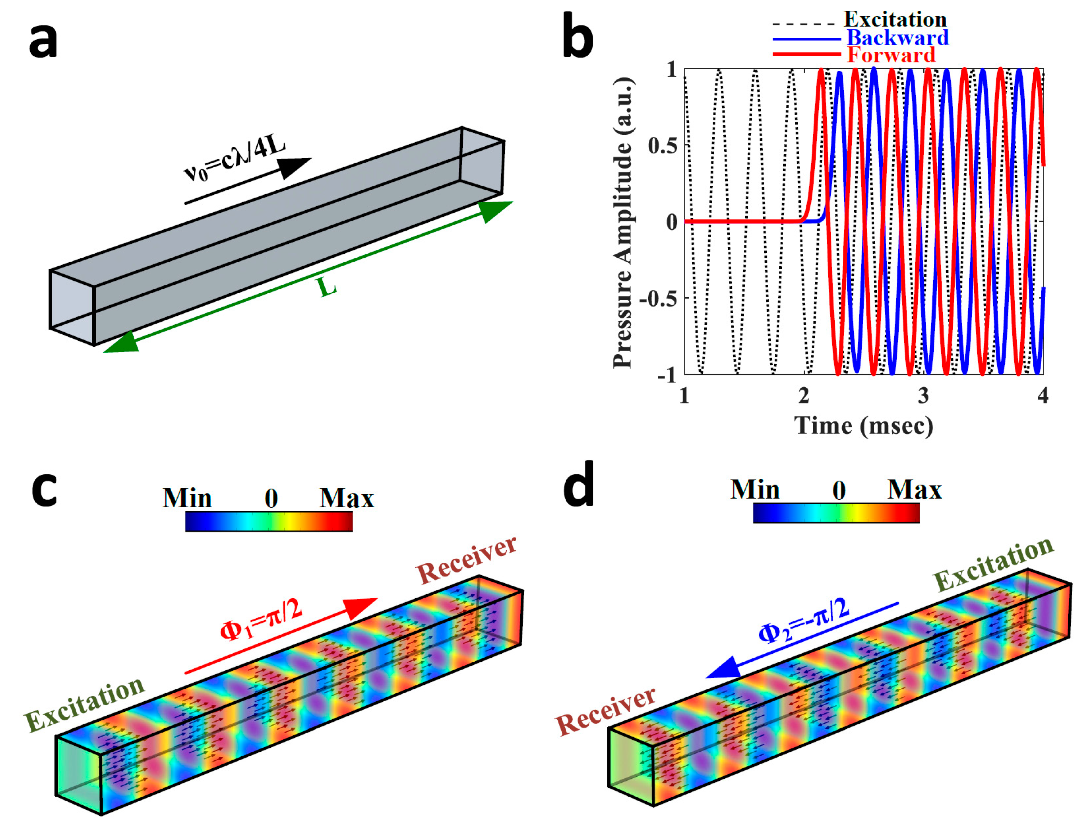
which is quite similar to the scattering matrix of an ideal gyrator, apart from a phase factor of . This constant phase factor, however, should not cause any concern as it can always be compensated by cascading the phase shifter with a regular reciprocal system that shifts the phase of the travelling waves by −90 degrees for both propagation directions. Hence, our non-reciprocal phase shifter indeed works as an acoustic gyrator for this choice of bias velocity. To prove this, we again perform time domain simulations, assuming a bias velocity motion of . Figure 4b depicts the transmitted signals corresponding to the forward (the solid red line) and backward (the solid blue line) propagation. Notice that the excitation signal is also marked with the dashed black line in the figure. It is obvious that there exists a differential transmission phase shift of 180 degrees between the forward and backward waves. It is further observed that the transmitted signal is led (lagged) by 90 degrees with respect to the excitation for forward (backward) propagation. These obviations are in accordance with the scattering matrix of Equation (3). The pressure field distributions corresponding to the forward and backward transmissions are also depicted in Figure 4c,d, respectively. The obtained results demonstrate how the proposed phase shifter realizes a gyrator for this choice of bias velocity.
4. Conclusions
In summary, we proposed a non-reciprocal acoustic phase shifter, providing different phase shifts for the forward and backward propagation of sound waves. To this end, we considered a simple acoustic waveguide that was filled with air. When the air within the waveguide was stationary, the signals travelling inside the waveguide experienced the same amount of phase shift regardless of the propagation direction. However, when a constant bias velocity was applied to the air, the structure became non-reciprocal and the sound waves travelling in opposite directions were subjected to different phase shifts. We further showed that, by changing the amount of bias velocity, one can tune the corresponding differential phase shift. Setting the differential phase shift to 180 degrees, we then realized an acoustic gyrator.
In comparison with the proposals leveraging nonlinear effects to induce non-reciprocity for acoustic waves, the main advantage of our scheme is that it is a fully linear. While non-reciprocal acoustic devices based on non-linearities only work for certain (high) levels of input power, the proposed non-reciprocal acoustic phase shifters and the gyrator work properly regardless of the amount of input power. Such linear non-reciprocal devices may have potential applications to realize various miniaturized and efficient components including isolators, circulators, band pass filters, power controllers, and modulators to mention a few.
Author Contributions
F.Z.-N. carried out the research work under the supervision of R.F. Both authors participated in writing the manuscript.
Funding
This research was funded by Swiss National Science Foundation (SNSF) under Grant No. 172487.
Conflicts of Interest
The authors declare no competing interests.
References
- Pozar, D. Microwave Engineering, 4th ed.; John Wiley & Sons: Hoboken, NJ, USA, 2005; ISBN 9780470631553. [Google Scholar]
- Tatarenko, A.S.; Srinivasan, G.; Bichurin, M.I. Magnetoelectric microwave phase shifter. Appl. Phys. Lett. 2006, 88, 183507. [Google Scholar] [CrossRef]
- How, H.; Vittoria, C. Microwave phase shifter utilizing nonreciprocal wave propagation. IEEE Trans. Microw. Theory Tech. 2004, 52, 1813–1819. [Google Scholar] [CrossRef]
- Babbitt, R.; Koscica, T.; Drach, W.; Didomenico, L. Ferroelectric phase shifters and their performance in microwave phased array antennas. Integr. Ferroelectr. 1995, 8, 65–76. [Google Scholar] [CrossRef]
- Hashemi, H.; Guan, X.; Komijani, A.; Hajimiri, A. A 24-GHz SiGe phased-array receiver—LO phase-shifting approach. IEEE Trans. Microw. Theory Tech. 2005, 53, 614–625. [Google Scholar] [CrossRef]
- Nikfalazar, M.; Sazegar, M.; Mehmood, A.; Wiens, A.; Friederich, A.; Maune, H.; Binder, J.R.; Jakoby, R. Two-Dimensional Beam-Steering Phased-Array Antenna with Compact Tunable Phase Shifter Based on BST Thick Films. IEEE Antennas Wirel. Propag. Lett. 2017, 16, 585–588. [Google Scholar] [CrossRef]
- Akiba, S.; Oishi, M.; Nishikawa, Y.; Minoguchi, K.; Hirokawa, J.; Ando, M. Photonic architecture for beam forming of RF phased array antenna. In Proceedings of the Conference on Optical Fiber Communication, Technical Digest Series, San Francisco, CA, USA, 9–13 March 2014. [Google Scholar]
- Creath, K. V Phase-Measurement Interferometry Techniques. Prog. Opt. 1988, 26, 349–393. [Google Scholar] [CrossRef]
- Woehrle, C.D.; Doyle, D.T.; Lane, S.A.; Christodoulou, C.G. Space Radiation Environment Testing of Liquid Crystal Phase Shifter Devices. IEEE Antennas Wirel. Propag. Lett. 2016, 15, 1923–1926. [Google Scholar] [CrossRef]
- Yan, Y.; Yao, J. A tunable photonic microwave filter with a complex coefficient using an optical RF phase shifter. IEEE Photonics Technol. Lett. 2007, 19, 1472–1474. [Google Scholar] [CrossRef]
- Chan, E.H.W.; Minasian, R.A. Photonic RF phase shifter and tunable photonic RF notch filter. J. Lightwave Technol. 2006, 24, 2676–2682. [Google Scholar] [CrossRef]
- Liao, L.; Samara-Rubio, D.; Morse, M.; Liu, A.; Hodge, D.; Rubin, D.; Keil, U.D.; Franck, T. High speed silicon Mach-Zehnder modulator. Opt. Express 2005, 13, 3129. [Google Scholar] [CrossRef] [PubMed]
- Dong, P.; Chen, L.; Chen, Y. High-speed low-voltage single-drive push-pull silicon Mach-Zehnder modulators. Opt. Express 2012, 20, 6163. [Google Scholar] [CrossRef] [PubMed]
- Roh, Y.S.; Moon, Y.J.; Park, J.; Yoo, C. A two-phase interleaved power factor correction boost converter with a variation-tolerant phase shifting technique. IEEE Trans. Power Electron. 2014, 29, 1032–1040. [Google Scholar] [CrossRef]
- Pagani, M.; Marpaung, D.; Eggleton, B.J. Ultra-wideband microwave photonic phase shifter with configurable amplitude response. Opt. Lett. 2014, 39, 5854–5857. [Google Scholar] [CrossRef] [PubMed]
- Cheng, Y.-Y.; Wyant, J.C. Phase shifter calibration in phase-shifting interferometry. Appl. Opt. 1985, 24, 3049. [Google Scholar] [CrossRef] [PubMed]
- Tarasov, N.; Perego, A.M.; Churkin, D.V.; Staliunas, K.; Turitsyn, S.K. Mode-locking via dissipative Faraday instability. Nat. Commun. 2016, 7, 12441. [Google Scholar] [CrossRef] [PubMed] [Green Version]
- Hamoir, G.; De La Torre Medina, J.; Piraux, L.; Huynen, I. Self-biased nonreciprocal microstrip phase shifter on magnetic nanowired substrate suitable for gyrator applications. IEEE Trans. Microw. Theory Tech. 2012, 60, 2152–2157. [Google Scholar] [CrossRef]
- Yanaga, M.; Shoji, Y.; Takamura, Y.; Nakagawa, S.; Mizumoto, T. Compact magnetooptical isolator with cobalt ferrite on silicon photonic circuits. Appl. Phys. Express 2015, 8, 082201. [Google Scholar] [CrossRef]
- Palomba, M.; Palombini, D.; Colangeli, S.; Ciccognani, W.; Limiti, E. Broadband Nonreciprocal Phase Shifter Design Technique. IEEE Trans. Microw. Theory Tech. 2018, 66, 1964–1972. [Google Scholar] [CrossRef]
- Khanikaev, A.B.; Fleury, R.; Mousavi, S.H.; Alù, A. Topologically robust sound propagation in an angular-momentum-biased graphene-like resonator lattice. Nat. Commun. 2015, 6, 8260. [Google Scholar] [CrossRef] [PubMed] [Green Version]
- Fleury, R.; Sounas, D.L.; Sieck, C.F.; Haberman, M.R.; Alù, A. Sound isolation and giant linear nonreciprocity in a compact acoustic circulator. Science 2014, 343, 516–519. [Google Scholar] [CrossRef] [PubMed]
- He, C.; Ni, X.; Ge, H.; Sun, X.C.; Chen, Y.B.; Lu, M.H.; Liu, X.P.; Chen, Y.F. Acoustic topological insulator and robust one-way sound transport. Nat. Phys. 2016, 12, 1124–1129. [Google Scholar] [CrossRef] [Green Version]
- Shen, Z.; Zhang, Y.L.; Chen, Y.; Zou, C.L.; Xiao, Y.F.; Zou, X.B.; Sun, F.W.; Guo, G.C.; Dong, C.H. Experimental realization of optomechanically induced non-reciprocity. Nat. Photonics 2016, 10, 657–661. [Google Scholar] [CrossRef] [Green Version]
- Zhang, Z.; Koroleva, I.; Manevitch, L.I.; Bergman, L.A.; Vakakis, A.F. Nonreciprocal acoustics and dynamics in the in-plane oscillations of a geometrically nonlinear lattice. Phys. Rev. E 2016, 94, 032214. [Google Scholar] [CrossRef] [PubMed]
- Coulais, C.; Sounas, D.; Alù, A. Static non-reciprocity in mechanical metamaterials. Nature 2017, 542, 461–464. [Google Scholar] [CrossRef] [PubMed] [Green Version]
- Zhang, J.; Peng, B.; Özdemir, Ş.K.; Liu, Y.X.; Jing, H.; Lü, X.Y.; Liu, Y.L.; Yang, L.; Nori, F. Giant nonlinearity via breaking parity-time symmetry: A route to low-threshold phonon diodes. Phys. Rev. B 2015, 92, 115407. [Google Scholar] [CrossRef] [Green Version]
- Merkel, A.; Willatzen, M.; Christensen, J. Dynamic Nonreciprocity in Loss-Compensated Piezophononic Media. Phys. Rev. Appl. 2018, 9, 034033. [Google Scholar] [CrossRef]
- Wang, Q.; Yang, Y.; Ni, X.; Xu, Y.L.; Sun, X.C.; Chen, Z.G.; Feng, L.; Liu, X.P.; Lu, M.H.; Chen, Y.F. Acoustic asymmetric transmission based on time-dependent dynamical scattering. Sci. Rep. 2015, 5, 10880. [Google Scholar] [CrossRef] [PubMed] [Green Version]
- Popa, B.I.; Cummer, S.A. Non-reciprocal and highly nonlinear active acoustic metamaterials. Nat. Commun. 2014, 5, 3398. [Google Scholar] [CrossRef] [PubMed] [Green Version]
- Li, N.; Ren, J. Non-reciprocal geometric wave diode by engineering Asymmetric shapes of nonlinear materials. Sci. Rep. 2014, 4, 6228. [Google Scholar] [CrossRef] [PubMed]
- Fleury, R.; Sounas, D.L.; Haberman, M.R.; Alù, A. Nonreciprocal Acoustics. Acoust. Today 2015, 11, 14. [Google Scholar]
- Blanchard, A.; Sapsis, T.P.; Vakakis, A.F. Non-reciprocity in nonlinear elastodynamics. J. Sound Vib. 2018, 412, 326–335. [Google Scholar] [CrossRef]
- Fleury, R.; Sounas, D.; Alù, A. An invisible acoustic sensor based on parity-time symmetry. Nat. Commun. 2015, 6, 5905. [Google Scholar] [CrossRef] [PubMed] [Green Version]
- Fleury, R.; Khanikaev, A.B.; Alù, A. Floquet topological insulators for sound. Nat. Commun. 2016, 7, 11744. [Google Scholar] [CrossRef] [PubMed] [Green Version]
- Zangeneh-Nejad, F.; Fleury, R. Acoustic Analogues of High-Index Optical Waveguide Devices. arXiv, 2018; arXiv:1802.02784. [Google Scholar]
- Zangeneh-Nejad, F.; Fleury, R. Performing Mathematical Operations using High-Index Acoustic Metamaterials. arXiv, 2018; arXiv:1803.02589. [Google Scholar]
- Esfahlani, H.; Karkar, S.; Lissek, H.; Mosig, J.R. Acoustic carpet cloak based on an ultrathin metasurface. Phys. Rev. B 2016, 94, 014302. [Google Scholar] [CrossRef]
- Fleury, R.; Alù, A. Extraordinary sound transmission through density-near-zero ultranarrow channels. Phys. Rev. Lett. 2013, 111, 055501. [Google Scholar] [CrossRef] [PubMed]
- Fleury, R.; Alù, A. Metamaterial buffer for broadband non-resonant impedance matching of obliquely incident acoustic waves. J. Acoust. Soc. Am. 2014, 136, 2935–2940. [Google Scholar] [CrossRef] [PubMed]
- Landi, M.; Zhao, J.; Prather, W.E.; Wu, Y.; Zhang, L. Acoustic Purcell Effect for Enhanced Emission. Phys. Rev. Lett. 2018, 120, 114301. [Google Scholar] [CrossRef] [PubMed] [Green Version]
- Ulbricht, R.; Sakuma, H.; Imade, Y.; Otsuka, P.H.; Tomoda, M.; Matsuda, O.; Kim, H.; Park, G.W.; Wright, O.B. Elucidating gigahertz acoustic modulation of extraordinary optical transmission through a two-dimensional array of nano-holes. Appl. Phys. Lett. 2017, 110, 091910. [Google Scholar] [CrossRef]
- Wang, P.; Lu, L.; Bertoldi, K. Topological Phononic Crystals with One-Way Elastic Edge Waves. Phys. Rev. Lett. 2015, 115, 104302. [Google Scholar] [CrossRef] [PubMed]
- Li, Y.; Jiang, X.; Li, R.Q.; Liang, B.; Zou, X.Y.; Yin, L.L.; Cheng, J.C. Experimental realization of full control of reflected waves with subwavelength acoustic metasurfaces. Phys. Rev. Appl. 2014, 2, 064002. [Google Scholar] [CrossRef]
- Cheng, Y.; Zhou, C.; Yuan, B.G.; Wu, D.J.; Wei, Q.; Liu, X.J. Ultra-sparse metasurface for high reflection of low-frequency sound based on artificial Mie resonances. Nat. Mater. 2015, 14, 1013–1019. [Google Scholar] [CrossRef] [PubMed]
- Ni, X.; He, C.; Sun, X.C.; Liu, X.P.; Lu, M.H.; Feng, L.; Chen, Y.F. Topologically protected one-way edge mode in networks of acoustic resonators with circulating air flow. New J. Phys. 2015, 17, 053016. [Google Scholar] [CrossRef]
- Wang, W.; Xie, Y.; Konneker, A.; Popa, B.I.; Cummer, S.A. Design and demonstration of broadband thin planar diffractive acoustic lenses. Appl. Phys. Lett. 2014, 105, 101904. [Google Scholar] [CrossRef]
- Zhu, Y.F.; Zou, X.Y.; Liang, B.; Cheng, J.C. Acoustic one-way open tunnel by using metasurface. Appl. Phys. Lett. 2015, 107, 113501. [Google Scholar] [CrossRef] [Green Version]
- Chen, Y.; Liu, H.; Reilly, M.; Bae, H.; Yu, M. Enhanced acoustic sensing through wave compression and pressure amplification in anisotropic metamaterials. Nat. Commun. 2014, 5, 5247. [Google Scholar] [CrossRef] [PubMed] [Green Version]
- Ni, X.; Wu, Y.; Chen, Z.G.; Zheng, L.Y.; Xu, Y.L.; Nayar, P.; Liu, X.P.; Lu, M.H.; Chen, Y.F. Acoustic rainbow trapping by coiling up space. Sci. Rep. 2014, 4, 7038. [Google Scholar] [CrossRef] [PubMed] [Green Version]
- Devaux, T.; Tournat, V.; Richoux, O.; Pagneux, V. Asymmetric Acoustic Propagation of Wave Packets Via the Self-Demodulation Effect. Phys. Rev. Lett. 2015, 115, 234301. [Google Scholar] [CrossRef] [PubMed]
- Zangeneh-Nejad, F.; Fleury, R. Acoustic Birefringence via Non-Eulerian Metamaterials. arXiv, 2018; arXiv:1803.09070. [Google Scholar]
- Zhai, S.; Chen, H.; Ding, C.; Shen, F.; Luo, C.; Zhao, X. Manipulation of transmitted wave front using ultrathin planar acoustic metasurfaces. Appl. Phys. A Mater. Sci. Process. 2015, 120, 1283–1289. [Google Scholar] [CrossRef]
- Popa, B.I.; Shinde, D.; Konneker, A.; Cummer, S.A. Active acoustic metamaterials reconfigurable in real time. Phys. Rev. B 2015, 91, 220303. [Google Scholar] [CrossRef]
- Wang, X.P.; Wan, L.L.; Chen, T.N.; Liang, Q.X.; Song, A.L. Broadband acoustic diode by using two structured impedance-matched acoustic metasurfaces. Appl. Phys. Lett. 2016, 109, 044102. [Google Scholar] [CrossRef]
- Li, Y.; Shen, C.; Xie, Y.; Li, J.; Wang, W.; Cummer, S.A.; Jing, Y. Tunable asymmetric transmission via lossy acoustic metasurfaces. Phys. Rev. Lett. 2017, 119, 035501. [Google Scholar] [CrossRef] [PubMed]
- Huang, Y.L.; Sun, H.X.; Xia, J.P.; Yuan, S.Q.; Ding, X.L. Multi-band asymmetric acoustic transmission in a bended waveguide with multiple mechanisms. Appl. Phys. Lett. 2016, 109, 013501. [Google Scholar] [CrossRef]
- Sun, H.; Zhang, S.; Yuan, S.; Xia, J. Experimental verification of manipulating propagation directions of transmitted waves in asymmetric acoustic transmission. Appl. Phys. A Mater. Sci. Process. 2016, 122, 328. [Google Scholar] [CrossRef]
- Song, K.; Kim, J.; Hur, S.; Kwak, J.H.; Lee, S.H.; Kim, T. Directional Reflective Surface Formed via Gradient-Impeding Acoustic Meta-Surfaces. Sci. Rep. 2016, 6, 32300. [Google Scholar] [CrossRef] [PubMed] [Green Version]
- Ouyang, S.; He, H.; He, Z.; Deng, K.; Zhao, H. Acoustic one-way mode conversion and transmission by sonic crystal waveguides. J. Appl. Phys. 2016, 120, 104504. [Google Scholar] [CrossRef] [Green Version]
- Zhang, S.; Zhang, Y.; Guo, Y.; Leng, Y.; Feng, W.; Cao, W. Realization of Subwavelength Asymmetric Acoustic Transmission Based on Low-Frequency Forbidden Transmission. Phys. Rev. Appl. 2016, 5, 034006. [Google Scholar] [CrossRef]
- Fan, X.; Qiu, C.; Zhang, S.; Ke, M.; Liu, Z. Highly asymmetric interaction forces induced by acoustic waves in coupled plate structures. J. Appl. Phys. 2015, 118, 244506. [Google Scholar] [CrossRef] [Green Version]
- Xia, J.P.; Sun, H.X.; Yuan, S.Q. Modulating Sound with Acoustic Metafiber Bundles/639/301/1005/639/766/25/3927/128 article. Sci. Rep. 2017, 7, 8151. [Google Scholar] [CrossRef] [PubMed]
- Zhu, Y.F.; Gu, Z.M.; Liang, B.; Yang, J.; Yang, J.; Yin, L.L.; Cheng, J.C. Asymmetric sound transmission in a passive non-blocking structure with multiple ports. Appl. Phys. Lett. 2016, 109, 103504. [Google Scholar] [CrossRef]
- Zhang, Z.; Tian, Y.; Cheng, Y.; Wei, Q.; Liu, X.; Christensen, J. Topological Acoustic Delay Line. Phys. Rev. Appl. 2018, 9. [Google Scholar] [CrossRef]
- Shen, C.; Xie, Y.; Li, J.; Cummer, S.A.; Jing, Y. Acoustic metacages for sound shielding with steady air flow. J. Appl. Phys. 2018, 123, 034032. [Google Scholar] [CrossRef]
- Zuo, C.Y.; Xia, J.P.; Sun, H.X.; Ge, Y.; Yuan, S.Q.; Liu, X.J. Broadband acoustic logic gates in a circular waveguide with multiple ports. Appl. Phys. Lett. 2017, 111, 243501. [Google Scholar] [CrossRef]
Figure 1.
Concept of non-reciprocal phase shifters. (a) Schematic of a typical non-reciprocal phase shifter in microwave engineering. The device is composed of a waveguide that is partially filled with a ferrite slab on which a constant magnetic bias field is applied. The amount of differential phase shift between the forward and backward waves can be controlled by changing the magnetic field. (b) Acoustic equivalent of the microwave phase shifter shown in panel a. The structure consists of an acoustic waveguide that is filled with a fluid on which a velocity motion of is applied. The waveguide provides different phase shifts of and for forward and backward transmission, respectively.

Figure 2.
Scattering parameters of the proposed non-reciprocal acoustic phase shifters. (a) Employing Doppler spectral analysis, the variations of and versus the bias velocity are calculated. When the fluid inside the waveguide is stationary, the forward and backward waves are subject to the same amount of phase shift (). However, they start acquiring different amounts of transmission phase shifts () by increasing the bias velocity from zero. (b) Variation of the phase of the scattering parameters (S12 and S21) of the structure versus the bias velocity, calculated via full-wave numerical simulations. Numerical simulations validate our Doppler spectral analysis.

Figure 3.
Demonstration of the proposed non-reciprocal acoustic phase shifter. (a) An excitation pulse (the solid blue line) is considered to be injected to the left side of the waveguide of Figure 1b. The signal that is received at the other side (the red dashed line) is in phase with the excitation when . (b) Same as panel a, except that a bias velocity of , which corresponds to the phase shift of , is imparted on the fluid. The transmitted signal is now led by 180 degrees with respect to the excitation. (c,d) The same process has been followed when the waveguide is excited from the right side. In the case of the stationary fluid (panel c), the time evolution of the transmitted signal is exactly identical to that of panel a, stemming from the reciprocity of the structure. When assuming however, the received signal is lagged (not led) by 180 degrees with respect to the input field, manifesting the non-reciprocity of the structure in phase.

Figure 4.
Demonstration of an acoustic gyrator via the proposed non-reciprocal acoustic phase shifter. (a) Bias velocity motion is set such that it corresponds to a transmission phase shift of for forward, and that of for backward direction. (b) Time profile of the transmitted signals associated with forward (solid red line) and backward (solid blue line) waves. The excitation signal is also marked with a dashed black line. (c,d) Pressure filed distribution corresponding to the forward and backward transmissions. The obtained results reveal that the acoustic phase shifter under study works as a gyrator for this choice of bias velocity.

© 2018 by the authors. Licensee MDPI, Basel, Switzerland. This article is an open access article distributed under the terms and conditions of the Creative Commons Attribution (CC BY) license (http://creativecommons.org/licenses/by/4.0/).
Share and Cite
MDPI and ACS Style
Zangeneh-Nejad, F.; Fleury, R. Doppler-Based Acoustic Gyrator. Appl. Sci. 2018, 8, 1083. https://doi.org/10.3390/app8071083
AMA Style
Zangeneh-Nejad F, Fleury R. Doppler-Based Acoustic Gyrator. Applied Sciences. 2018; 8(7):1083. https://doi.org/10.3390/app8071083
Chicago/Turabian StyleZangeneh-Nejad, Farzad, and Romain Fleury. 2018. "Doppler-Based Acoustic Gyrator" Applied Sciences 8, no. 7: 1083. https://doi.org/10.3390/app8071083
Note that from the first issue of 2016, this journal uses article numbers instead of page numbers. See further details here.