1. Introduction
Among all sports injuries, head injuries represent the most severe risks to athletes’ health. Nowadays, serious or fatal accidents are not uncommon on sports fields: in 2015, a 21-year-old footballer died in Argentina’s fifth tier after his head collided with a concrete wall at the edge of the pitch [
1]. A similar case in 2008 involved a Croatian football player who suffered a fatal head injury after colliding with a barrier positioned about three metres from the sideline [
2].
The protection of athletes when they collide with barriers is a critical issue for the improvement of passive safety in sports fields. The lack of safety requirements in current sporting regulations is considered the main cause of injuries or fatalities. For example, current football requirements prevent the risk of impact for the athlete only by prescribing a minimum distance of dangerous equipment from the boundary lines of the playing pitch. They do not make mention of the physical behaviours of players during their performance and the correlated potential impact energy of the athlete in overstepping the boundary lines of the regular pitch [
3,
4]. Moreover, they do not prescribe specific actions (e.g., by covering sports facilities with high energy-absorption materials) in attenuating the potentials correlated to accidental impacts of the player’s head against external sports equipment.
To ensure the players’ safety, the introduction of materials with high-energy absorption properties in the surrounding area of the playing field is of primary importance. The good cushioning performance of the polymeric foams, beyond a unique combination of properties such as light weight, good ageing, chemical resistance, and inertness, has ensured the application of these materials in protective sporting equipment over the past few years [
5,
6,
7].
According to the standards [
8,
9,
10,
11], the evaluation of the impact performance for a protective device requires the use of an instrumented drop test rig, where a hemispherical mass falling on the prototype to be analysed reproduces the event of a head crash (the most life-threatening situation). The head injury risk is then assessed through “Head Injury Models” (HIM), which are based on the impacting mass acceleration vs. time curve acquired during the impact event [
12]. This testing procedure requires a dedicated falling weight impact apparatus and reveals various difficulties including the friction of the falling group, the high number of samples required, and a long set-up time.
To overcome these problems, a numerical model for the impact behaviour of the foam protective devices is needed. However, the analysis of impact events on polymeric foam padding is a very complex mechanical issue. The nonlinear behaviour of the foam material, having rate-dependent viscoelastic properties, and the presence of impulsive forces make an exact analytic solution unattainable. Furthermore, when the phenomenon is analysed by a standard FEM approach, high foam deformations can lead to numerical instabilities and low accuracy of the numerical predictions [
13].
This paper concerns the design practice of new protective devices. The absorption behaviour of ethylene-vinyl acetate (EVA) foam mats at different impact energies was analysed by a numerical approach based on the mesh-free Element Galerkin method [
14,
15,
16]. As a case study, the impact behaviour of plates under different impact velocity is considered. The mechanical properties needed to define the constitutive model of the foam have been obtained by standard compressive quasi-static tests on small samples.
The proposed modelling practice was validated statistically on the basis of data obtained from low-velocity impact tests. The validation study was conducted, comparing the output results of the simulations with the experimental ones. To verify the validity of the simulations, as comparison parameters the missile acceleration curves, the “Coefficient of determination” (R2), and the “Root Mean Square Error” (RMSE) were used.
2. Materials and Methods
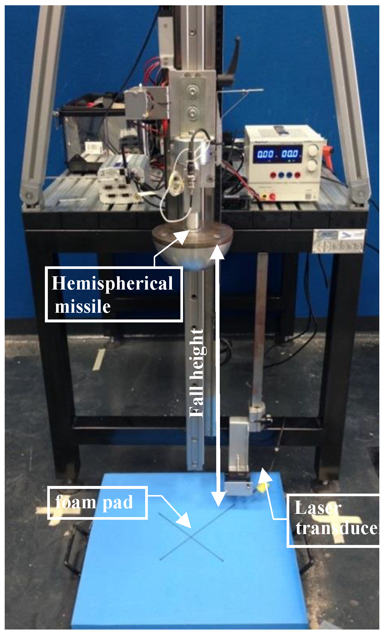
Low-velocity impact tests were performed on EVA foam mats through a low-velocity impact testing apparatus designed and built at the Fraunhofer Joint Lab IDEAS of the University of Naples Federico II. The experimental setup adopted in the present work is shown in
Figure 1.
According to the ASTM F1292 standard [
11], a hemispherical missile with 160 mm diameter and a mass of 4.6 kg, equipped with 500 g uniaxial accelerometer, was dropped from a height (through a guidance system) on the foam pad, which was fixed by an adhesive tape on a steel anvil. In each test the fall height of the missile was measured by a laser displacement sensor located close to the missile release mechanism. A second laser displacement sensor, positioned near the specimen surface and triggered by the missile position, was used to measure the missile velocity just before impacting on the foam pad.
The material on which tests were performed was an EVA closed cell foam with a density of 35 kg/m3 in two different thickness of 50 mm and 70 mm. EVA foam is a closed cell foam made from ethylene-vinyl acetate and blended copolymers. It shows a high level of chemical cross-linking and, therefore, can be classified as a semi-rigid foam with a fine uniform cell structure. Because of those properties, the EVA foam is frequently used in applications where both high impact and vibration absorption, suitability for thermo-forming and thermo-moulding, are needed. Compared to other materials used for these applications, such as polyethylene foams, EVA foam is softer, more resilient, and has greater recovery characteristics after compression.
In a recent study by Lanzotti et al. [
4], football player movements in common gaming actions were analysed. Movements were considered potentially damaging when they occurred near the boundary lines of the regular pitch, since they lead players to overstep the boundary lines in an uncontrolled manner with a residual kinetic energy. The players’ impact velocities against objects placed close to the playing field were also measured. The expected values of the impact velocities for object placed at distances of 1, 2 and 3 m away from the field boundary were equal to 4.5 m/s, 5.2 m/s, and 6.2 m/s, respectively. These results were adopted as reference values for the initial velocities of the impacting missile in the explorative tests carried out in the present study for realistically reproducing head impacts of increasing severity. Deeper analysis is, however, needed to definitively choose a set of initial missile velocities that take into account the difference between real impacts of athletes and those reproduced by a stiff standard test rig.
All the impact tests were carried out according to the practice reported in [
10]. To evaluate the correct fall heights,
hm, corresponding to the three above reported velocities, a statistical model of friction between the linear guide carriage and the drop assembly during the vertical fall, was implemented and used. Furthermore, for each specimen the corresponding critical fall height (
CFH), namely the maximum fall height from which a life-threatening head injury would not be expected to occur, was calculated. For this purpose, the iterative statistical procedure of [
17] was employed. At a velocity of 6.2 m/s, the test was not performed on the EVA sample with a thickness of 50 mm because the corresponding fall height was higher than the
CFH of this kind of specimen. The acceleration–time curve was acquired for each test. From this curve, the injury parameters maximum acceleration
amax and head injury criterion (
HIC) were derived. In particular, an Online FAMOS routine was used to calculate the HIC values for any time sub-interval [
ti,
tf] of the overall time span of the impact. This procedure gave back the HIC score as the maximum of all those calculated and the corresponding time interval [
ti,
tf].
Compression Tests
The material behaviour was also analysed through a series of compressive tests with quasi-static loads. As far as the specimen preparation, test loading application, and data analysis go, the EN ISO 844:2014 and ASTM D 1621 standards were followed.
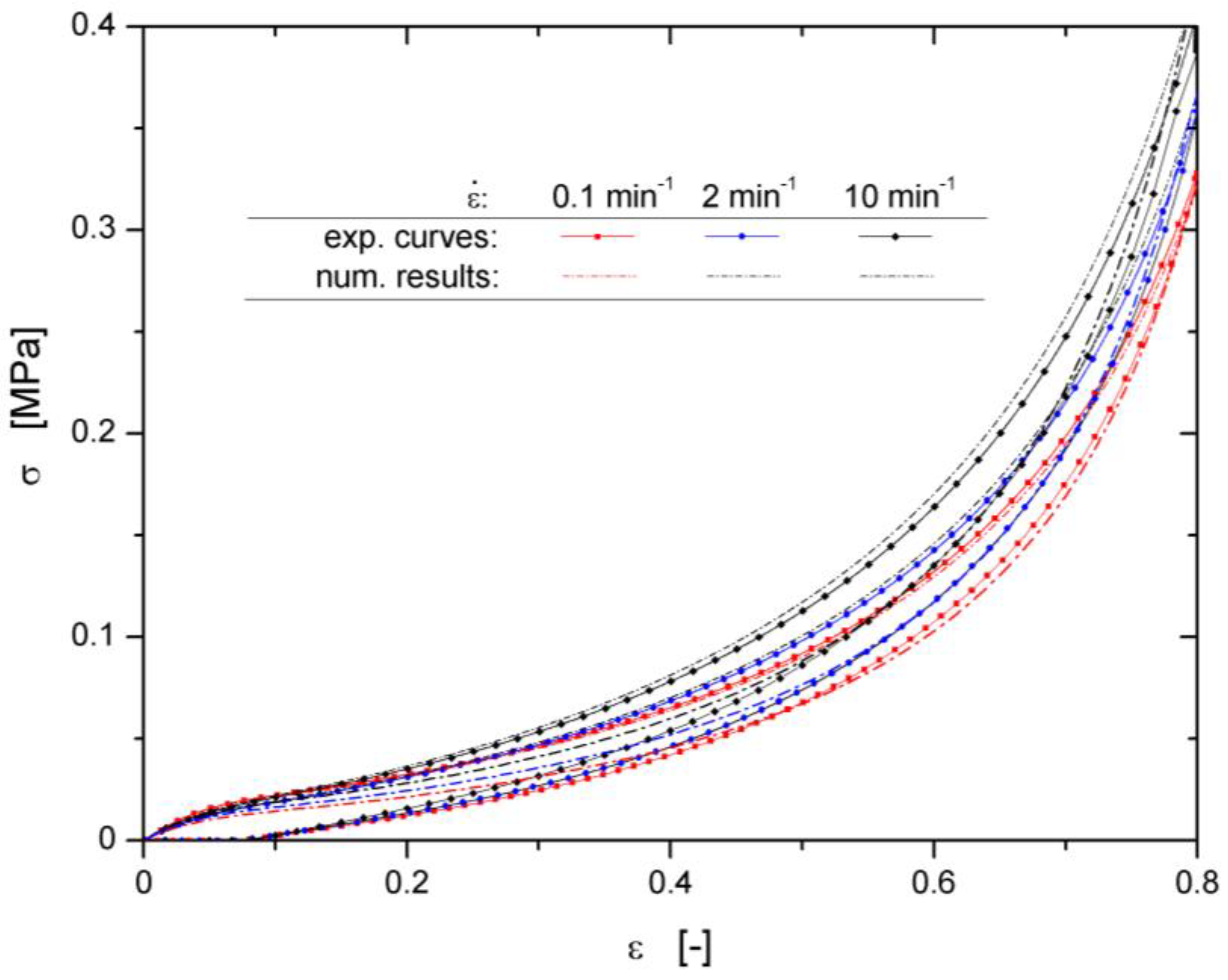
Compression tests were performed on cubic specimens having a size of 50 × 50 × 50 mm3. Testing loads were applied on specimens by an electro-mechanical universal testing machine (INSTRON 5566, Norwood, MA, USA) digitally controlled by BLUEHILL 2 software. More specifically, the tests were carried out under displacement control, with longitudinal strain rates equal to 0.1, 2.0 and 10 min−1. To get data on foam hysteretic behaviour, specimens were compressed until a nominal strain of 80% was reached and then unloaded with the same strain rate amplitude of the loading phase. During each test, the value of the applied load and the specimen height reductions were acquired by the machine control software to obtain the foam engineering stress-strain curve.
Some compressive stress–strain curves are reported in
Figure 2, which provides information on the foam mechanical performance. The observed mechanical behaviour is consistent with that of flexible foam. Specifically, an initial linear region was evident and suggested a stiff mechanical response at the onset. This region was followed by a portion of the curve with a lower stiffness. A final stiff region of the stress–strain curve was observed as it is usually reported for flexible foams. The central region of the curve did not show a plateau (a zero-slope region) and was characterized by a lower stiffness compared with the other two regions of the graph. A compressive modulus of elasticity (
E) of 0.4136 MPa was calculated from the slope of the initial linear region (
of the stress–strain curve. Furthermore, the results of
Figure 2 reveal a stiffening effect when the strain rate is increased, which represents a typical aspect of the viscoelastic behaviour of the material.
3. Meshless Simulations
Several computational difficulties arose in the analysis of missile dynamic effects on the foam pad. The non-linear behaviour and the extremely large strain on the polymeric foam, together with the presence of an impulsive load, required a very small time step to be fixed to ensure the numerical solution of the pad equilibrium equations. For this reason, the central differencing scheme [
18] was adopted to avoid the inversion of the pad stiffness matrix in each calculation step.
Moreover, the large deformations of the foam made the Lagrangian mesh extremely skewed and compressed. The remarkable distortion of the constitutive elements led to a reduction in the accuracy of the solution algorithm. To avoid accuracy reduction, periodic remeshing of the pad volume during the evolution of the simulation was needed. However, this solution produced a very high computational cost and the remeshing advantages were partially reduced from the degradation of accuracy due to the projection operation of the field variables from the old meshes to the new ones.
To overcome these difficulties, the Element-Free Galerkin (EFG) method of Belytchko et al. [
16] was adopted to analyse the pad behaviour under missile impact. Using this method, the solution is constructed entirely in terms of a set of nodes and no elements are needed. The unknown displacement field
is searched in the form given by
where
is the vector of the monomial basis functions and
is a vector of unknown parameters. These are determined at any point
x by solving the following optimization problem:
where
are the unknown values assumed by the displacement field at node I having coordinate
,
is a weighting function with compact support, and NP is the number of nodes within the support of
w. When the solution to Equation (2) is substituted into Equation (1), we obtain for the approximation
the expression
with
being the shape functions of the EFG method given by
where
and
, with
The discretized equilibrium equations were derived by substituting the approximating function in the weak form of equilibrium conditions and carrying out numerical integration [
15].
It is worth noting that the convergence of the Galerkin method chosen to discretize the problem at hand depended both on the approximation adopted for the unknown functions and the numerical integration of the weak form. To achieve the linear exactness solution in the Galerkin approximation, some integration constraints had to be met [
19].
Therefore, the Lagrangian strain smoothing strategy described in [
20] was used for the domain integration by Gauss quadrature. Finally, since the EFG shape functions are not interpolation functions, the essential boundary conditions were enforced by the transformation method proposed in [
21].
Numerical Modelling
Drop impact tests on EVA square pads having thickness equal to 50 and 70 mm were simulated numerically using the commercial code LS-DYNA.
The calculation grids of the pads and the missile, as well as the background element mesh needed to carry on the Gaussian numerical quadrature, were built using the pre-processor HYPERMESH, starting from 3D models generated in the Solidworks geometrical modelling environment. In order to reduce the computational burden, the drop assembly geometry was simplified by considering only the hemispherical missile as an impacting object (with a mass equal to the fall group mass).
The hemispherical missile, made of aluminium alloy, was discretized using tetrahedral elements with an average size equal to 10 mm. Its deformations during the interaction with the pads were negligible compared to those of the pad. For this reason, the missile was modelled as a rigid body using the function MAT_RIGID (*MAT_020) [
22].
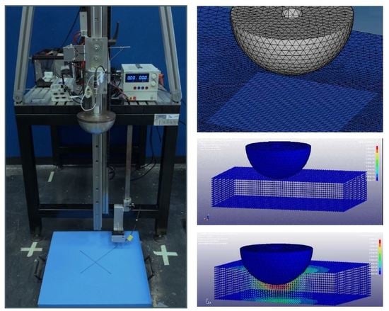
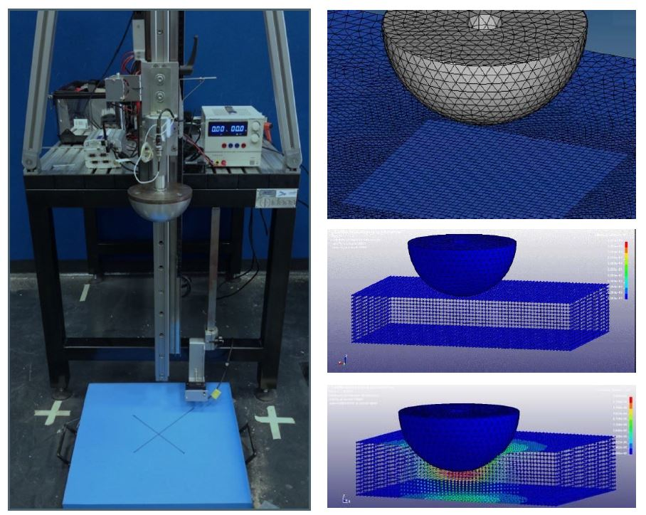
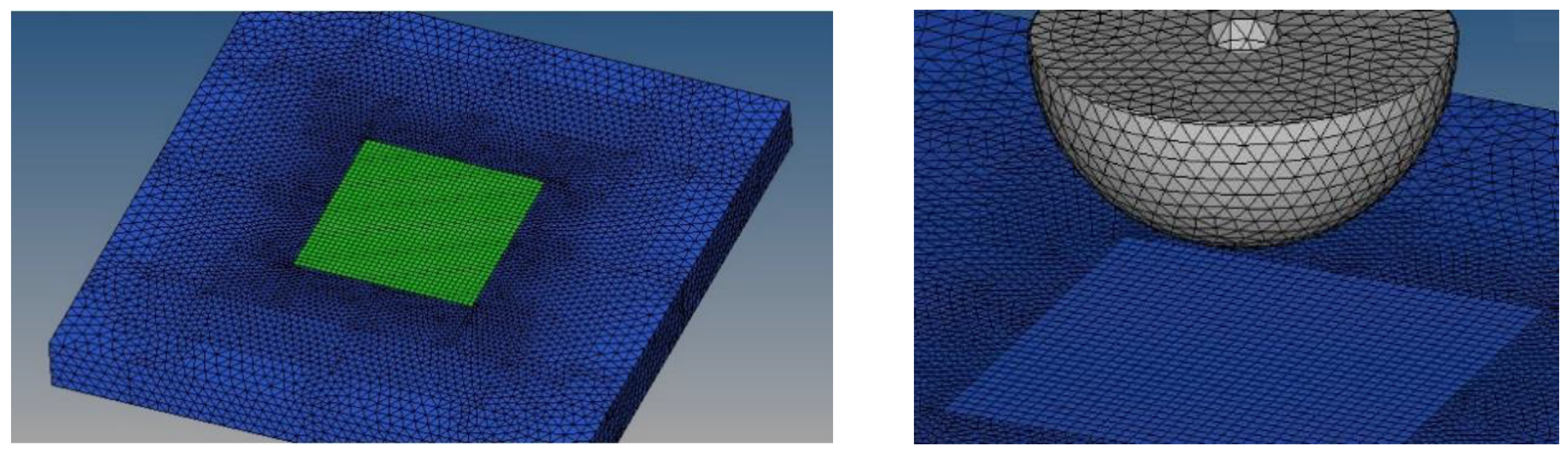
To generate the nodes grid and the background mesh, the pads were divided into two distinct volumes and different node spacing was adopted for each volume. The first volume is the “impact zone,” which has a prismatic shape with a base of size 200 mm × 200 mm, a height equal to the pad thickness, and includes the foam material more severely deformed by the missile actions (
Figure 3). This volume was meshed with small hexahedral elements having edge size equal to 5 mm. The remaining portion of the pad was instead discretized with tetrahedral elements having a gradually increasing size from 5 mm at the inner boundary to around 10 mm at the external edges of the pad.
The MAT_LOW_DENSITY_FOAM (*MAT57) [
22] was used as the foam constitutive model. This model is defined in terms of a foam compression curve, the Young’s modulus, the Poisson ratio, and some constitutive parameters defining the hysteretic and viscoelastic aspects of the material response. The foam unloading behaviour was controlled by the hysteretic unloading factor, HU, and the SHAPE parameter, both reported in
Table 1. HU ranged in value between zero and one. Low values of HU shifted the unloading path downward. The lowest value of HU did not sufficiently account for energy loss, so the SHAPE factor was adjusted to increase energy loss by further shifting the unloading curve down. Viscous effects were controlled by a DAMP factor. Increasing the DAMP values is equivalent to adding a material damper. The suggested range of DAMP was between 0.05 and 0.5.
The values of previous foam parameters were obtained by ‘tuning’ the results of a series of numerical simulations of the compressive tests with those obtained by the real compressive tests. A comparison among experimental results and numerical predictions carried out with optimal values of these constitutive parameters is given in
Figure 2. Experimental data and numerical outcomes are in good agreement for the whole loading curves and for most of the unloading ones. The numerical model did not properly match the final part of the experimental unloading curves, since a part of the foam rearrangement takes place on a time scale greater than the compressive test time scale. However, in the following it will be shown that this does not influence the model accuracy in reproducing missile impacts on foam pads.
During the impact testing, penetration depths greater than the 80% of the pad thickness were observed. This clearly implies that for the higher impact velocities of the missile, the foam material is working in the densification phase of the stress–strain curve, where for small variations in the foam deformation the values of the compressive stress increase exponentially. However, by means of the compression tests, the real stress–strain curve of the foam was acquired only up to a nominal strain equal to 80%; after this threshold value of the strain specimen buckling started to occur.
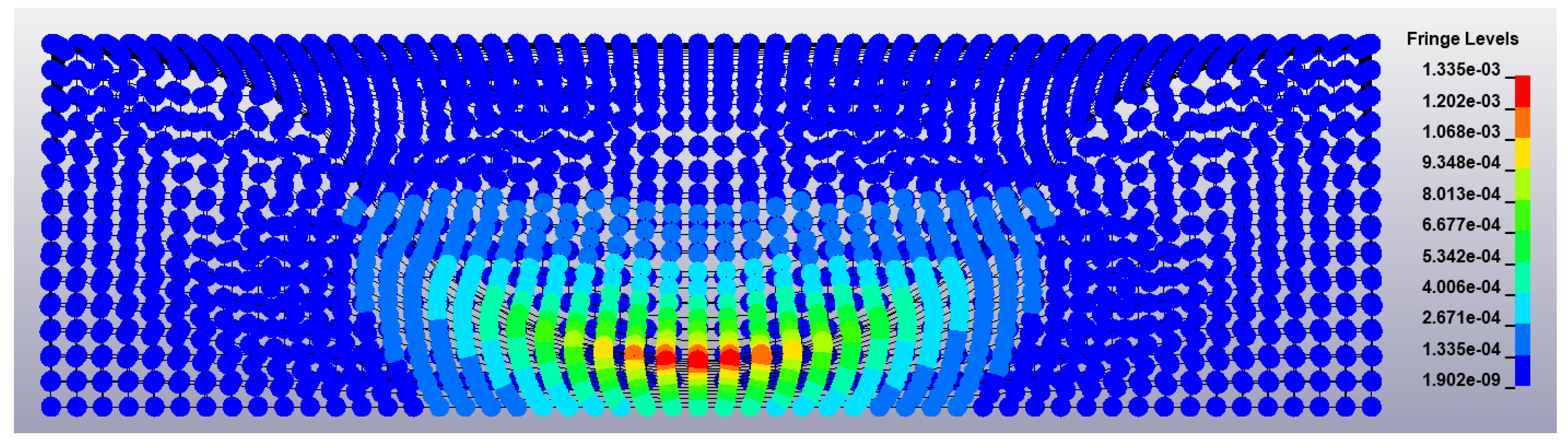
Therefore, to carry out the numerical impact modelling with higher velocities, the Du Bois extrapolation to the densification region [
23] was adopted for the EVA foam. Some results of a numerical simulation carried out by the developed model are reported in
Figure 4, where the deformed shape of a 50 mm pad and the through-the-thickness distribution of the Von Mises stress are shown.
4. Results
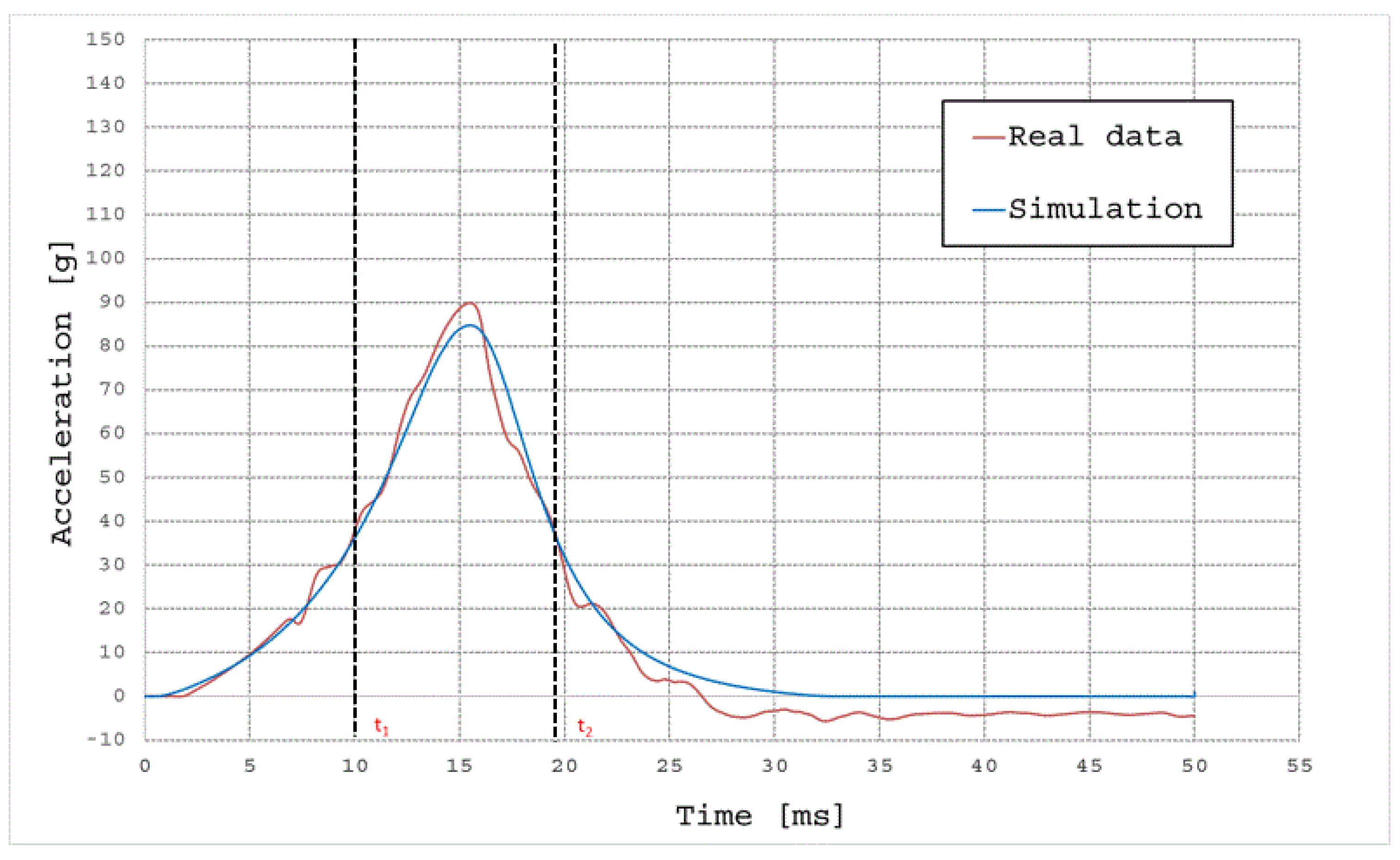
In
Figure 5, the simulated and experimental acceleration vs. time curves of the hemispherical missile impacting the EVA foam 50 mm at the velocity of 4.5 m/s are compared. In all the examined cases, to validate the numerical model using the statistical indexes
RMSE and
R2, only the most relevant part of the acceleration curves is used. More specifically, only the acceleration values belonging to the time range [
ti,
tf] derived from the algorithm used to calculate the HIC index were considered. Actually, this is the most injurious portion of the impact waveform, where the acceleration reached the highest values.
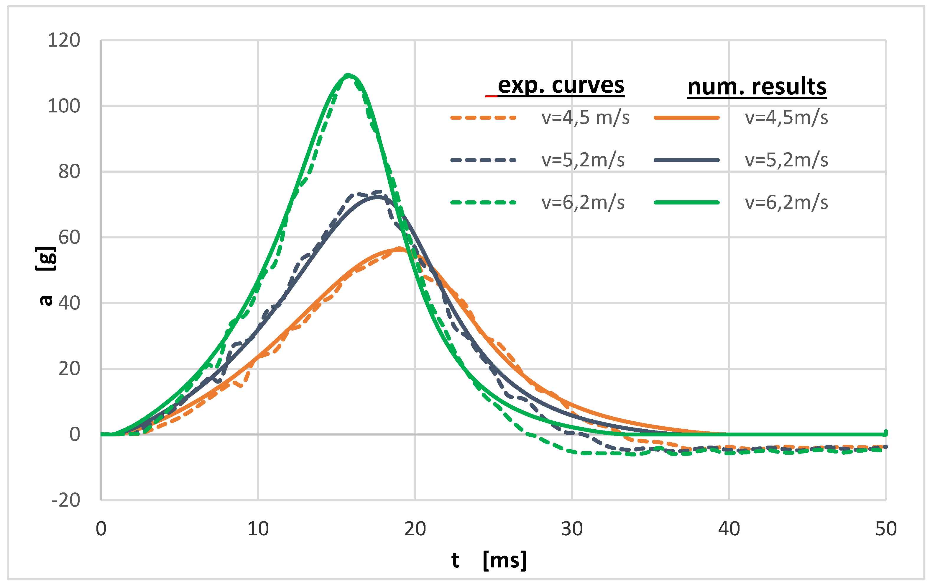
An overview of the simulated acceleration curves and the experimental ones for EVA samples with a thickness of 70 mm is shown in
Figure 6. Instead, in
Table 2, for each testing value of the impacting missile velocity
Vtest and for each foam plate thickness, the drop height
Hm, the critical drop height
CDH, the time interval [
ti,
tf] where the comparison of the simulated and real test data is carried out, the maximum values of the acceleration reached in the real tests (
amax,r) and in the simulated ones (
amax,s), the
HIC values, (
HICr) and (
HICs), respectively, evaluated by experimental and numerical data, and finally the values of the two statistical indices,
RMSE and
R2, adopted to evaluate the predictive accuracy of the model are listed. These indices were calculated using data sampled from the experimental and numerical acceleration curves with two frequency values, a choice derived from the necessity of also checking the veracity of the statistical validation. Actually, this latter condition is verified when the values of the two indexes calculated under different sampling frequencies are very close.
Further analysis was conducted for the EVA mat 50 mm at the impact test velocity of 5.2 m/s. In this case, the comparison between the simulated and real acceleration curves was carried out separately for the initial, central, and final regions of the diagram shown in
Figure 7.
The results of the statistical analysis conducted in each of these regions are reported in
Table 3. It is evident in this table that the accuracy of this analysis is very different from that of the previous ones. The values of the
RMSE and
R2 indexes for the central region of the acceleration curve clearly indicate a poor correlation.
5. Discussion
As shown by the statistical analysis, the simulation succeeded in reproducing the physical phenomenon of a low-velocity impact test. The correct estimate of the a-max and HIC values by the simulation leads us to assess the risk of an athlete suffering an injury following a head impact, or in other words allows for ensuring an adequate level of protection for the athlete. The two curves of accelerations (real and simulated) show a similar trend, with discrepancies only in the last part of the impact event, where the simulation curve goes to zero and the real acceleration assumes negative values. This observed difference is due to the oscillations of the piezoelectric accelerometer before returning to zero values. This means that the simulations were performed correctly.
The values of the indexes
RMSE and
R2 in
Table 1 confirmed the good correlation between the experimental results and the simulated ones, except for the 50 mm EVA foam, which at an impact velocity of 5.2 m/s showed a remarkable difference in the region where the material reached the peak of acceleration (see
Figure 7 and
Table 3).
Regarding the data in
Table 2, it is worth observing that the test fall height for the EVA 50 mm corresponding to the impact velocity of 5.2 m/s (equal to 1.709 m) appears to be very close to the CFH of the architecture (equal to 1858 m). Moreover, the simulation data show that the material reaches the densification stage during this test, while the behaviour of the material was modelled by the Du Bois model and not by the data obtained from the compression tests. Thus, the lack of knowledge about the real behaviour of the EVA foam in the densification zone is responsible for the poor correlation between the simulation and the test results observed in region II of
Figure 7 and in
Table 3.
The numerical simulations allowed us to investigate the behaviour of EVA polymeric foams subjected to a low-velocity impact. The main strength of the model is that its accuracy is insensitive to the large strains suffered by the foam material, which instead are responsible of numerical instabilities with a typical FEM analysis [
14,
21].
Furthermore, the developed numerical model may be employed to analyse the passive safety properties of shields for sports equipment made of generic polymeric foam and can be used when basic characteristic parameters of the materials under examination are known, such as the density, the Young’s modulus, the Poisson ratio or the compressive stress–strain curve. The main application concerns the characterization of a foam mat under impact conditions. The use of the simulation in replacing the current testing standard is not feasible, as the deterioration of the absorption properties of the material in consecutive impacts is not contemplated in the model.
6. Conclusions
The purpose of this study was to create a versatile numerical model to simulate low-velocity impact tests on polymeric foam mats. The tool developed allows for the design and improvement of protective devices for sports safety without limitations due to the cost and time of an experimental test campaign.
A meshless method, namely the Element-Free Galerkin (EFG) method, has been adopted to overcome the limitations of the conventional finite element-based approaches and to achieve a high accuracy of the simulation. The main advantage of the proposed modelling procedure is that the foam constitutive properties needed for the analysis are just a few material parameters obtainable by standard laboratory testing.
A validation study has been carried out both by visual comparison of the impactor acceleration curves acquired during impact testing and numerical results and in terms of the statistical indexes R2 and RMSE. The results of the study show that the adopted approach leads to very accurate results when the foam mechanical behaviour is not in the densification phase. When this happens, instead, numerical results are affected by errors related to the extrapolation of the foam compressive stress–strain curve. However, this is not a serious drawback since, to limit the accelerations due to impact to tolerable values, it is necessary to avoid the exponential increments of foam stiffness characteristic of its densification phase.
Author Contributions
Conceptualization, A.L., S.O.; Data curation, F.P., G.A., A.G. and M.M.; Funding acquisition, S.O. and A.L.; Investigation, F.P., G.A., A.G. and M.M. F.P. and G.A wrote the paper; F.P. performed numerical modelling; G.A. planned and carried out the low-velocity impact tests; A.G. planned and performed the compression tests; M.M. performed the optimisation of the geometric features and experimental setup; Writing—review & editing, F.P., A.G., G.A. and M.M.; Supervision, S.O. and A.L.
Funding
This work was supported by the State of Saxony, the European Union (European Social Fund—ESF), the University of Naples Federico II under a bilateral project and the European LLP (Lifelong Learning Program) under Erasmus Traineeship agreement.
Acknowledgments
This study has been carried out within the scientific cooperation between Chemnitz University of Technology (TUC) and University of Naples Federico II. The authors would like to thank the European LLP (Lifelong Learning Programme), which, through the project “Erasmus Traineeship,” has funded the internship of the students Cecilia Maddaloni and Raffaele Moria at TU Chemnitz. Their work was essential for the collection and analysis of experimental data and the implementation of the simulation algorithm.
Conflicts of Interest
The authors declare no conflicts of interest related to this study.
References
- Sheen, T. Emanuel Ortega Dead: 21-Year-Old Footballer in Argentina’s Fifth Tier Dead after Suffering Horrific Head Injury after Collision with Concrete Wall. Independent. 14 May 2015. Available online: https://www.independent.co.uk/sport/football/news-and-comment/emanuel-ortega-dies-21-year-old-player-in-argentinas-fifth-tier-dead-after-suffering-horrific-head-10249706.html (accessed on 14 May 2015).
- Ilic, I.; Oxley, S. Soccer-Croatian player dies after hitting head on wall in match. Reuters. 3 April 2008. Available online: https://uk.reuters.com/article/soccer-europe-croatia-death/soccer-croatian-player-dies-after-hitting-head-on-wall-in-match-id UKL0393548520080403 (accessed on 3 April 2008).
- Odenwald, S.; Amodeo, G.; Costabile, G.; Lanzotti, A. Contribution to risk assessment in football by video analysis of overstepping boundary line events. Sports Eng. 2016, 19, 129–137. [Google Scholar] [CrossRef]
- Lanzotti, A.; Costabile, G.; Annino, G.; Amodeo, G.; Odenwald, S. Video-Analysis of player’s kinematics in running out of boundaries in Association football fields. Procedia Eng. 2016, 147, 234–239. [Google Scholar] [CrossRef]
- Jenkins, M. Materials in Sports Equipment; Woodhead Publishing Limited: Cambridbe, UK, 2003. [Google Scholar]
- Zhou, Y.J.; Lu, G.; Yang, J.L. Finite element study of energy absorption foams for headgear in football (soccer) games. Mater. Des. 2015, 88, 162–169. [Google Scholar] [CrossRef]
- Coelho, R.M.; de Sousa, R.J.A.; Fernandes, F.A.O.; Teixeira-Dias, F. New composite liners for energy absorption purposes. Mater. Des. 2013, 43, 384–392. [Google Scholar] [CrossRef]
- European Committee for Standardization. Impact Attenuating Playground Surfacing, Determination of Critical Fall Height; EN 1177:2008; CEN: Brussels, Belgium, 2008. [Google Scholar]
- American Society for Testing and Materials. Standard Test Method for Shock-Absorbing Properties of Playing Surface Systems and Materials; ASTM F355-01; ASTM: West Conshohocken, PA, USA, 2001. [Google Scholar]
- American Society for Testing and Materials. Standard Specification for Impact Indoor Wall/Feature Padding; ASTM F2440-04; ASTM: West Conshohocken, PA, USA, 2004. [Google Scholar]
- American Society for Testing and Materials. Standard Specification for Impact ttenuation of Surface Systems under and around Playground Equipment; ASTM F1292-04; ASTM: West Conshohocken, PA, USA, 2004. [Google Scholar]
- Cory, C.Z.; Jones, M.D.; James, D.S.; Leadbeatter, S.; Nokes, L.D.M. The potential and limitations of utilising head impact injury models to assess the likelihood of significant head injury in infants after a fall. Forensic Sci. Int. 2001, 123, 89–106. [Google Scholar] [CrossRef]
- Auricchio, F.; Veiga, L.B.; Lovadina, C.; Reali, A. Stability of some finite element methods for finite elasticity problems, Mixed finite element technologies. In CISM Courses and Lectures; Springer: Wien, Austria, 2009; Volume 509, pp. 179–206. [Google Scholar]
- Chen, Y.; Lee, J.; Eskandarian, A. Meshless Methods in Solid Mechanics; Springer Science & Business Media: New York, NY, USA, 2006. [Google Scholar]
- Liu, G.R. Meshfree Methods: Moving beyond the Finite Element Method; Taylor & Francis: Boca Raton, FL, USA, 2009. [Google Scholar]
- Belytschko, T.; Lu, Y.Y.; Gu, L. Element-Free Galerkin Methods. Int. J. Numer. Methods Eng. 1994, 37, 229–256. [Google Scholar] [CrossRef]
- Schwanitz, S.; Costabile, G.; Amodeo, G.; Odenwald, S.; Lanzotti, A. Modelling head impact safety performance of polymer-based foam protective devices. Procedia Eng. 2014, 72, 581–586. [Google Scholar] [CrossRef] [Green Version]
- Belytschko, T.; Liu, W.K.; Moran, B. Nonlinear Finite Elements for Continua and Structures; Wiley: Chichester, UK, 2000. [Google Scholar]
- Chen, J.S.; Wu, C.T.; Yoon, S.; You, Y. A stabilized conforming nodal integration for Galerkin mesh-free methods. Int. J. Numer. Methods Eng. 2001, 50, 435–466. [Google Scholar] [CrossRef]
- Chen, J.S.; Pan, C.; Roque, C.M.O.L.; Wang, H.P.A. Lagrangian reproducing kernel particle method for metal forming analysis. Comput. Mech. 1998, 22, 289–307. [Google Scholar] [CrossRef]
- Li, S.; Liu, W.K. Meshfree and particle methods and their applications. Appl. Mech. Rev. 2002, 55, 1–34. [Google Scholar] [CrossRef]
- Hallquist, J.O. Keyword User’s Manual Vol. II—Material Models; LS-DYNA R8.0; Livermore Software Technology Corporation: Livermore, CA, USA, 2015. [Google Scholar]
- Serifi, E.; Hirth, A.; Matthaei, S.; Mullerschon, H. Modelling of foams using MAT83–Preparation and evaluation of exfperimental data. In Proceedings of the 4th European LS-DYNA Users Conference, Ulm, Germany, 22–23 May 2003. [Google Scholar]
© 2018 by the authors. Licensee MDPI, Basel, Switzerland. This article is an open access article distributed under the terms and conditions of the Creative Commons Attribution (CC BY) license (http://creativecommons.org/licenses/by/4.0/).

 ,
, 


