Second-Harmonic Generation of Blue Light in GaN Waveguides
by
 and
and
Martin Rigler
1,*, 
Tinkara Troha
1,
Wei Guo
2,
Ronny Kirste
3,
Isaac Bryan
2,
Ramon Collazo
2,
Zlatko Sitar
2,3 and
Marko Zgonik
1,4 1
Faculty of Mathematics and Physics, University of Ljubljana, 1000 Ljubljana, Slovenia
2
Department of Materials Science and Engineering, North Carolina State University, Raleigh, NC 27606, USA
3
Adroit Materials, Inc., Suite 800, Morrisville, NC 27560, USA
4
Jožef Stefan Institute, 1000 Ljubljana, Slovenia
*
Author to whom correspondence should be addressed.
Appl. Sci. 2018, 8(8), 1218; https://doi.org/10.3390/app8081218
Submission received: 15 June 2018
/
Revised: 13 July 2018
/
Accepted: 18 July 2018
/
Published: 25 July 2018
(This article belongs to the Special Issue Nonlinear Optical Materials and Phenomena)
Abstract
:Featured Application
Nonlinear optical conversion of visible laser diode sources into the blue and UV spectral region.
Abstract
Second-harmonic generation was studied in III-metal-polar GaN films grown on sapphire substrates by metalorganic chemical vapor deposition and formed into ridge waveguides. Broadband near-IR femtosecond pulses of an optical parametric amplifier system were injected by end-fire coupling and the nonlinear response was measured while tuning the central wavelength. A prominent peak was found at 450 nm for 1140 nm thick and 10 μm wide GaN waveguides. The measured second-harmonic peak was in agreement with the modal-dispersion phase matching condition calculated using the dispersion of the extraordinary refractive indices of GaN obtained by prism coupling.
1. Introduction
The rapidly expanding field of photonics has a great need for efficient and compact coherent light sources in the blue and ultraviolet (UV) regions. Short wavelengths allow for precise focusing and generation of very fine patterns, while the high photon energy facilitates strong absorption in many materials, leading to efficient material processing [1,2]. Laser diode technology used for the generation of UV light involves a number of challenges including low carrier injection and high threshold pump power, a lack of transparent and UV-resistant optical materials, and increased sensitivity to defects and surface roughness. Surface roughness and other anomalies inside the crystal can lead to strong wavefront distortions and scattering losses, an effect encountered especially with short wavelengths like UV [1,2,3,4]. Studies have shown that AlGaN alloys offer unique properties and have great potential to overcome the disadvantages listed above. While there are some reports on the fabrication of AlGaN-based LEDs in deep UV [5,6,7,8,9], very limited information about direct-emitting AlGaN semiconductor lasers is available [10,11]. Recent studies have been conducted on AlGaN-based optically-pumped UV laser structures, but electrically-pumped lasers with emissions below 320 nm have not yet been demonstrated [11,12,13]. Challenges related to the fabrication of electrically pumped GaN-, Al-GaN- and AlN-based UV laser diodes mainly stem from; (1) the deep Si-donor and Mg-acceptor levels that hinder successful carrier injection; and (2) the high strain fields and dislocation densities that are due to large lattice mismatches between the substrate and active layers [14,15,16].
AlGaN alloys have unique linear and nonlinear optical characteristics that permit the utilization of this material for efficient nonlinear conversion into the blue and UV wavelength regions. The two most important properties are a wide transparency window and large nonlinear optical coefficients. Both GaN and AlN have a wide bandgap, corresponding to wavelengths shorter than the visible spectrum. The transparency window of GaN ranges from 13.6 µm to 365 nm, while AlN remains transparent down to 200 nm [2,17]. AlGaN belongs to the 6mm point group, which lacks a center of inversion, and thus has five nonzero nonlinear optical coefficients from which only the two independent components, d31 and d33, need to be considered [2,18]. The experimental value of the largest second-order coefficient, d33, ranges from 5.82 to 10.6 pmV−1 [19]. Modal-dispersion phase matching or quasi-phase matching is required with AlGaN to exploit its nonlinearity since the birefringence is not sufficient to sustain an efficient second-harmonic generation (SHG), as was shown in our previous studies [20,21]. While SHG in GaN and AlGaN has been reported occasionally, only limited data are available for wavelengths below 500 nm. The limitations in this wavelength range are often related to low-quality materials or challenges in waveguide fabrication, which leads to significant scattering and losses. However, with the recent developments in metalorganic chemical vapor deposition growth (MOCVD) and the processing of GaN and AlGaN, new opportunities to investigate SHG in these wide bandgap materials have arisen.
For quasi-phase matching, a periodically modulated nonlinear structure is needed, which alternates the sign of the nonlinear coefficient in regular intervals and corrects for the relative phase mismatch between the fundamental and the frequency-doubled light without matching the phase velocities [22]. The polarity-controlled growth of +c and −c polarity regions of GaN can be achieved through adequate substrate preparation. The configuration in which the Ga-atoms bond, with three bonds toward the surface, is referred to as N-polar (or −c orientation), while the 180° rotated configuration is referred to as III-metal-polar (+c) [23].
In this work, we show the feasibility of III-metal polar GaN waveguides for SHG using modal-dispersion phase matching (MDPM), which takes advantage of the fact that the waveguide modes of different orders have different effective refractive index dispersion relations [24,25]. More specifically, we demonstrate the generation of light with λ = 450 nm in 1140 nm thick and 10 μm wide GaN waveguides. Due to the dependence of the effective refractive index on the dimensions of the waveguide and the wavelength, the pump waveguide mode of order p at pump wavelength λp and the SHG waveguide mode of order q > p at λSHG = λq/2 can be phase matched. The demonstration of SHG in AlGaN waveguides in the blue spectral region is understood as a step to extend the wavelengths of coherent light sources into the ultraviolet C spectral region via SHG. The final goal is to efficiently generate coherent light down to 200 nm through quasi-phase matching using periodically polled AlN waveguides [26].
The effective refractive index of the waveguide mode at a particular wavelength depends on the refractive indices of the waveguide and the substrate, and on the dimensions of the waveguide [27,28]. To excite the largest nonlinear coefficient d33, the polarization of in-coupled and out-coupled light is set to transverse magnetic (TM), and therefore the extraordinary refractive indices of the GaN and sapphire substrate must be taken into account. We used the dispersion of the extraordinary index for III-metal-polar GaN waveguides as obtained by a prism coupling study and described by the Sellmeier dispersion formula [21]:
where A = 4.3 and B = 195.4 nm. The extraordinary refractive index dispersion relationship for sapphire is given in the work of Malitson and Dodge [29]. In this study, an isotropic approximation [21,30] and a planar waveguide approximation [27] were used for the calculation of effective refractive indices due to weak birefringence and the large width-to-thickness ratio of the waveguides used. The second-harmonic power in a planar waveguide, where linear losses at pump and second harmonic generation (SHG) wavelengths are neglected, is expressed as [24]:
where L is the interaction length, W is the waveguide thickness, Pω is the fundamental power at the waveguide front facet, neff,2ω and neff,ω are the effective extraordinary refractive indices of the waveguide modes at the fundamental and SHG frequencies, respectively. The function h (Δβ) is given by:
This function represents a wave-vector mismatch term, where Δβ describes the difference between the propagation constants of the pump and SH waves.
The overlap integral Γ [24]:
is a dimensionless quantity normalized to 1 when the two interacting modes ψp,λ(z) and ψq,λ/2(z)—that are the transverse field distributions of the optical field amplitudes associated with the waveguide modes p and q at the fundamental and SH frequencies [24,31]—perfectly overlap in the transverse direction. It limits the number of waveguide modes that lead to efficient nonlinear conversion.
2. Materials and Methods
In this study, III-metal-polar GaN waveguides were used. A 1200 nm thick Ga polar GaN was grown on a low-temperature AlN buffer layer on sapphire using an MOCVD reactor. The growth temperature was 1040 °C with Ga (C2H5)3 (triethylgallium) and NH3 as the source gases. Details on the growth can be found elsewhere [31,32,33,34,35]. To transform planar waveguides into rectangular waveguides of selected widths, a standard photolithography process was used with the resulting waveguide widths ranging from 3–50 μm [35,36]. The final measurements were performed on samples with parallel waveguides of 10 μm width and 10 μm spacing.
Figure 1a presents a cross-sectional scanning electron microscopy (SEM) image of a waveguide facet that was used to couple-in the light into the waveguides. A cross-sectional trench was prepared using the following procedure: First, a 1 μm thick platinum protective layer was deposited using an ion-beam induced deposition with a 0.43 nA beam current; next, a cross-section using a 6.5 nA ion beam was milled. This was followed by a 80 pA milling of the exposed cross-section to obtain a polished surface. The thickness of the GaN waveguides was determined by the SEM analysis of the cross-sectional samples to be around 1150 nm. Although the waveguides exhibited very smooth surfaces, the analysis of the image taken by a CCD camera mounted above the sample revealed that most of the light scattering took place at the side surfaces of the waveguides. To confirm this, SEM images from the side facets were also recorded. It was found that the roughness of the sides was especially high for the waveguides with a stripe width below 5 μm. This is highlighted by a direct comparison of waveguides with a side roughness of 3 μm and 20 μm wide, as presented in Figure 1b. In addition, sidewall roughness is relatively more important in narrower waveguides, therefore, most SHG measurements were performed on GaN waveguides of 10 μm width and 1 mm length. In order to produce waveguides of an appropriate length, straight lines perpendicular to the waveguide direction were scribed by a UV laser on the back of the sapphire wafer. The wafer was then cleaved along the scribed lines.
The fabricated waveguides were used to probe SHG in GaN waveguides at room temperature. Figure 2 presents schematics of the experimental setup used to investigate the nonlinear response in GaN waveguides. A Ti:sapphire laser was used as the excitation source. Typical excitation wavelengths were in the range of 850–950 nm, which led to a second-harmonic response in the blue. Femtosecond pulses were injected into the waveguide by the end-fire coupling technique. The SHG signal generated in the waveguide was separated from the pump wave and analyzed with a spectrograph and a photon counting camera.
The output of the femtosecond laser system was nearly identical to that of a transform-limited fundamental pulse with a tunable central wavelength. The pulse duration was 40 fs (full-width at half-maximum, FWHM), the repetition rate was 1 kHz, and the spectral width was 30 nm (FWHM). The pulse energy was wavelength dependent from 1 to 100 µJ and could be controlled by a tunable neutral density (ND) filter, which was used before the end-fire coupling system. The beam diameter was adapted with a beam expander to the size of the in-coupling lens for efficient focusing. The coupling lenses and sample holder were mounted on xyz translation stages enabling precise positioning of the focal point of the laser beam onto the front facet of the waveguide. The output beam was focused onto the front face of the waveguide using a lens with a 10 mm focal length. The size of the beam at the waveguide facet was approximately 10 μm. This is equal to the waveguide width in order to dominantly excite the fundamental mode in the y-direction. The efficiency of coupling was constantly monitored with two CCD detectors as shown in Figure 2b and Figure 3a–c. The out-coupled light was collimated and filtered, and the SHG signal was directed to the detection system. The camera was operated using the gated regime and was synchronized to the femtosecond system repetition rate.
3. Results and Discussion
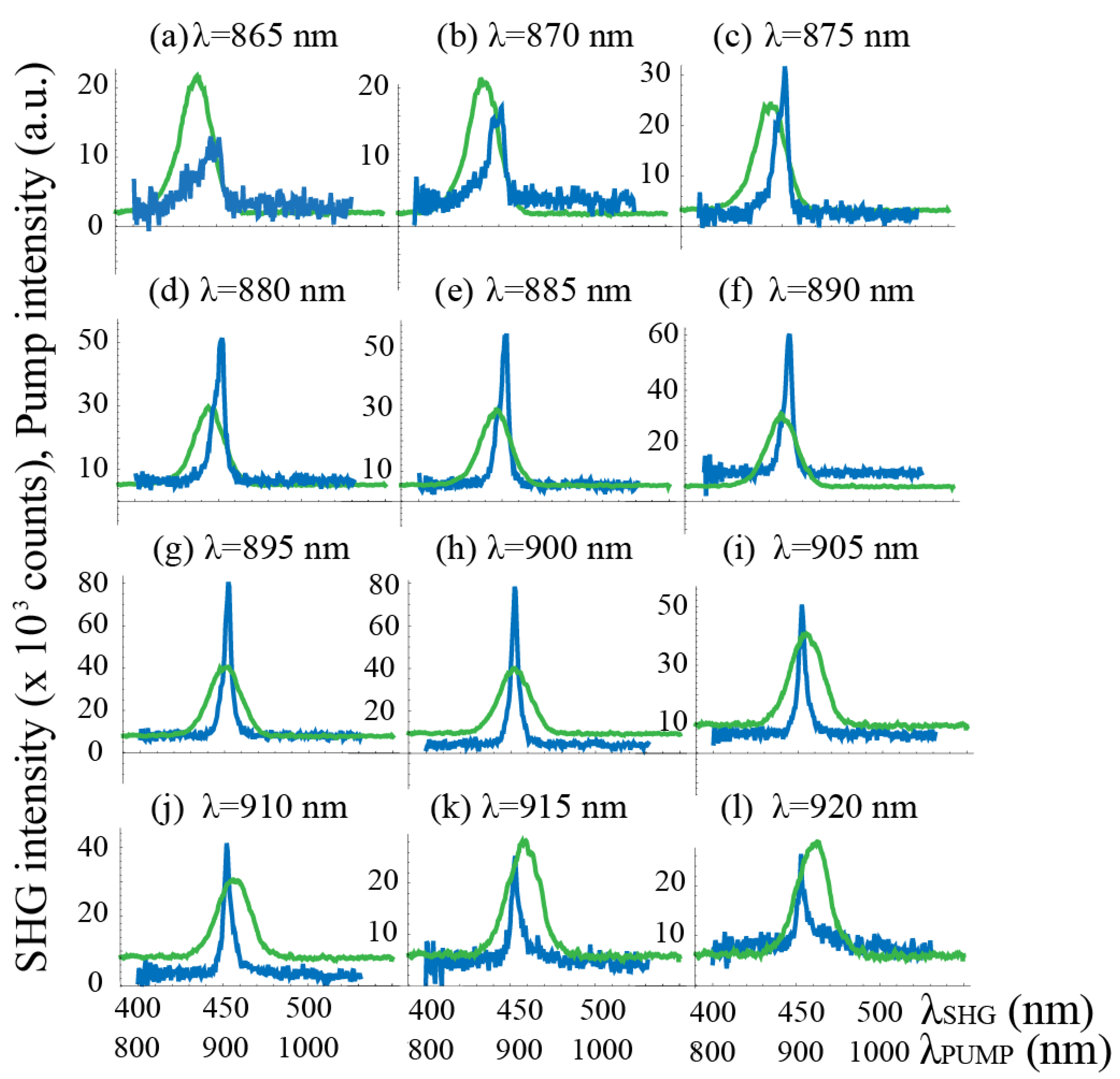
Figure 4 shows the second-harmonic response of GaN waveguides to excitation with different wavelengths ranging from 850 nm to 950 nm. The green curves show the spectral distribution of the excitation source and the blue curves show the corresponding SH response. A clear, relatively strong peak of the SHG signal was observed at a constant wavelength of 450 nm while scanning the pump wavelength spectrum. Maximum SHG response (blue curve) can be seen in Figure 4g,h with the central pump wavelengths of 895 nm and 900 nm. In order to explain the SHG peak at 450 nm the dispersions of the effective refractive indices for the pump and SHG waveguide modes were analyzed.
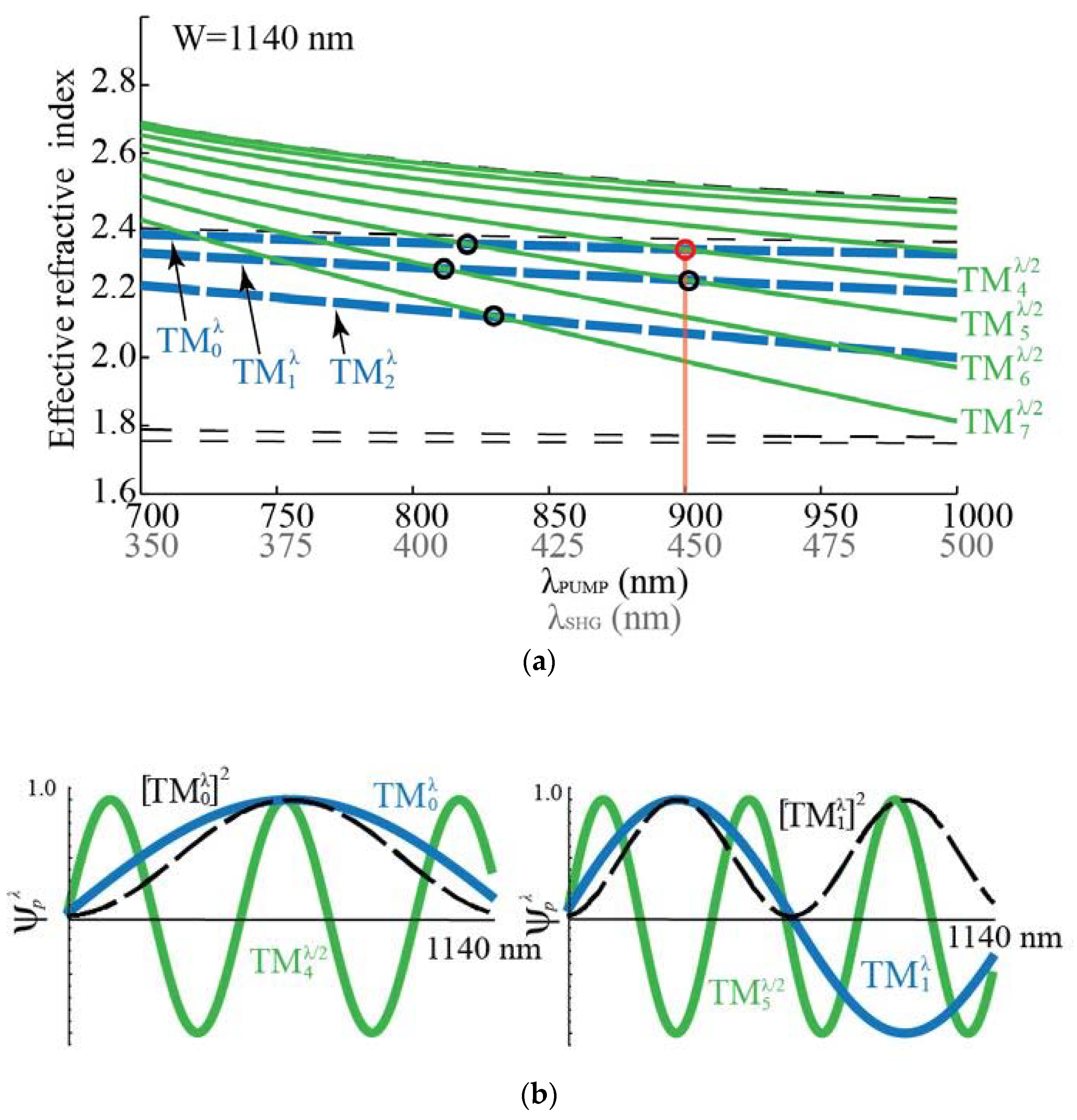
In Figure 5a the dispersion curves for a 1140 nm thick GaN waveguide on a sapphire substrate are shown. For the calculation, a planar waveguide approximation was used [27]. This was justified as the waveguides were 10 µm wide. Extraordinary refractive indices for GaN in the measured pump- and SHG-wavelength ranges are given by Equation (1). As indicated by the circles in Figure 5, the MDPM condition is true for the interaction between the fundamental pump mode and the fourth SHG mode, and for the first pump mode and fifth SHG mode, both at a pump wavelength λ of approximately 900 nm:
where λ is the pump wavelength. Both possible waveguide interactions are schematically shown in Figure 5b.
The fulfillment of the phase matching is only one of the necessary conditions for efficient SHG generation. In waveguide interactions, the overlap integral Γ, detailed in Equation (4), must also be considered. Although phase-matching conditions for two combinations of waveguide modes at the pump wavelength of 900 nm are met, the overlap integrals reveal that the interaction from Equation (5) is dominant and thus responsible for the measured SHG peak. Taking only the overlap into account, the conversion efficiency for the MDPM interaction described by Equation (6) is 35 times lower than that described by Equation (5). Furthermore, it could not be measured separately in our waveguides. In Table 1 the overlap integrals are compared for other possible interactions indicated by black circles in Figure 5. The interaction:
shows the largest overlap. However, the excitation of the first pump mode was less efficient, therefore, this SH peak was not observed. A small additional peak in Figure 4a could be attributed to this interaction.
The total efficiency of SHG can be estimated as the following: Taking the large waveguide aspect ratio (1.1 µm to 10 µm), losses by reflection at the front surface, and coupling to the unwanted waveguide modes into account, approximately 4% of a 1 mW input beam is coupled into the pump mode for conversion. Inside the waveguide, propagation losses were also observed, mainly due to the scattering from the waveguide sidewalls as shown in Figure 3a. However, these were negligible in comparison with the coupling losses. By using Equation (2) it was estimated that nearly 100 nW of blue light was generated.
4. Conclusions
In this study, we measured the nonlinear response of GaN waveguides grown on sapphire substrates through modal-dispersion phase matching. We compared experimental results to the calculations of the effective refractive index and the overlap of different combinations of waveguide modes. The relatively strong SHG peak obtained was in agreement with the theoretical predictions, therefore confirming the adequateness of the dispersion calculations and the accuracy of the measured refractive indices of GaN waveguides obtained by prism coupling in our previous study. This study can be seen as a first step towards integrated devices that emit coherent light in the blue and UV spectral regions based on second-harmonic generation in polarity controlled AlGaN waveguides.
Author Contributions
Conceptualization, M.Z. and Z.S.; Methodology, M.R., T.T., M.Z., Validation, M.R.; Formal Analysis, M.R., T.T., Investigation, M.R. and T.T., Resources, W.G., I.B., R.K., and R.C., Data Curation, M.R., Writing—Original Draft, M.R., and M.Z., Writing—Review&Editing, M.R. and M.Z., Visualization, M.R., Supervision, Z.S., R.C. and M.Z.
Funding
Partial financial support from NSF (DMR-1108071, DMR-1312582, ECCS-1508854, DMR-1508191), ARO (W911NF-15-2-0068, W911NF-14-C-0008) is acknowledged. The work was also finacially supported by the Slovenian Research Agency research core funding (P1-0192) and project (N1-0021).
Conflicts of Interest
The authors declare no conflicts of interest.
References
- Nakamura, S.; Pearton, S.; Fasol, G. The Blue Laser Diode, 2nd ed.; Springer: Berlin, Germany, 2000. [Google Scholar]
- Morkoc, H. Nitride Semiconductors and Devices; Springer: New York, NY, USA, 1999. [Google Scholar]
- Paschotta, R. Encyclopedia of Laser Physics and Technology, 1st ed.; Wiley-VCH: Berlin, Germany, 2008. [Google Scholar]
- Silfvast, T.W. Laser Fundamentals, 2nd ed.; Cambridge University Press: New York, NY, USA, 2004. [Google Scholar]
- Taniyasu, Y.; Kasu, M.; Makimoto, T. An aluminium nitride light-emitting diode with a wavelength of 210 nanometres. Nature 2006, 441, 325–328. [Google Scholar] [CrossRef] [PubMed]
- Fischer, A.J.; Allerman, A.A.; Crawford, M.H.; Bogart, K.H.A.; Lee, S.R.; Kaplar, R.J.; Chow, W.W.; Kurtz, S.R.; Fullmer, K.W.; Figiel, J.J. Room-temperature direct current operation of 290 nm light-emitting diodes with milliwatt power levels. Appl. Phys. Lett. 2004, 84, 3394. [Google Scholar] [CrossRef]
- Zhang, H.Y.; He, X.H.; Shih, Y.H.; Schurman, M.; Feng, Z.C.; Stall, R.A. Study of nonlinear optical effects in GaN:Mg epitaxial film. Appl. Phys. Lett. 1996, 69, 2953. [Google Scholar] [CrossRef]
- Nishida, T.; Saito, H.; Kobayashi, N. Efficient and high-power AlGaN-based ultraviolet light-emitting diode grown on bulk GaN. Appl. Phys. Lett. 2001, 79, 711. [Google Scholar] [CrossRef]
- Kneissl, M.; Kolbe, T.; Chua, C.; Kueller, V.; Lobo, N.; Stellmach, J.; Knauer, A.; Rodriguez, H.; Einfeldt, S.; Yang, Z.; et al. Advances in group III-nitride-based deep UV light-emitting diode technology. Semicond. Sci. Technol. 2011, 26, 014036. [Google Scholar] [CrossRef]
- Kneissl, M.; Yang, Z.; Teepe, M.; Knollenberg, C.; Schmidt, O.; Kiesel, P.; Johnson, N.M.; Schujman, S.; Schowalter, L.J. Ultraviolet semiconductor laser diodes on bulk AlN. J. Appl. Phys. 2007, 101, 123103. [Google Scholar] [CrossRef]
- Yoshida, H.; Kuwabara, M.; Yamashita, Y.; Takagi, Y.; Uchiyama, K.; Kan, H. AlGaN-based laser diodes for the short-wavelength ultraviolet region. New J. Phys. 2009, 11, 125013. [Google Scholar] [CrossRef]
- Xie, J.; Mita, S.; Bryan, Z.; Guo, W.; Hussey, L.; Moody, B.; Schlesser, R.; Kirste, R.; Gerhold, M.; Collazo, R.; et al. Lasing and longitudinal cavity modes in photo-pumped deep ultraviolet AlGaN heterostructures. Appl. Phys. Lett. 2013, 102, 171102. [Google Scholar] [CrossRef]
- Yoshida, H.; Yamashita, Y.; Kuwabara, M.; Kan, H. A 342-nm ultraviolet AlGaN multiple-quantum-well laser diode. Nat Photonics 2008, 2, 551–554. [Google Scholar] [CrossRef]
- Collazo, R.; Mita, S.; Xie, J.; Rice, A.; Tweedie, J.; Dalmau, R.; Sitar, Z. Implementation of the GaN lateral polarity junction in a MESFET utilizing polar doping selectivity. Phys. Status Solidi A 2010, 207, 45–48. [Google Scholar] [CrossRef]
- Jeon, S.-R.; Ren, Z.; Cui, G.; Su, J.; Gherasimova, M. Investigation of Mg doping in high-Al content p-type AlxGa1−xN (0.3 < x < 0.5). Appl. Phys. Lett. 2005, 86, 082107. [Google Scholar]
- Dalmau, R.; Moody, B.; Schlesser, R.; Mita, S.; Xie, J.; Feneberg, M.; Neuschl, B.; Thonke, K.; Collazo, R.; Rice, A.; et al. Growth and Characterization of AlN and AlGaN Epitaxial Films on AlN Single Crystal Substrates. J. Electrochem. Soc. 2011, 158, H530. [Google Scholar] [CrossRef]
- Chowdhury, A.; Ng, H.M.; Bhardwaj, M.; Weimann, N.G. Second-harmonic generation in periodically poled GaN. Appl. Phys. Lett. 2003, 83, 1077. [Google Scholar] [CrossRef]
- Strite, S.; Morkoc, H. GaN, AlN, and InN: A review. J. Vac. Sci. Technol. B Microelectron. Nanometer Struct. 1992, 10, 1237–1266. [Google Scholar] [CrossRef]
- Pezzagna, S.; Brault, J.; de Micheli, M.; Vennegues, P.; Wieck, A.D.; Massies, J. GaN, a new material for integrated nonlinear optics. Proc. ECIO 2007, 25–27. [Google Scholar]
- Rigler, M.; Buh, J.; Hoffmann, M.P.; Kirste, R.; Bobea, M.; Mita, S.; Gerhold, M.D.; Collazo, R.; Sitar, Z.; Zgonik, M. Optical characterization of Al- and N-polar AlN waveguides for integrated optics. Appl. Phys. Express 2015, 8, 042603. [Google Scholar] [CrossRef]
- Rigler, M.; Zgonik, M.; Hoffmann, M.P.; Kirste, R.; Bobea, M.; Collazo, R.; Sitar, Z.; Mita, S.; Gerhold, M. Refractive index of III-metal-polar and N-polar AlGaN waveguides grown by metal organic chemical vapor deposition. Appl. Phys. Lett. 2013, 102, 221106. [Google Scholar] [CrossRef]
- Hum, S.D.; Fejer, M.M. Quasi-phase matching. C. R. Phys. 2007, 8, 180–198. [Google Scholar] [CrossRef]
- Stutzmann, M.; Ambacher, O.; Eickhoff, M.; Karrer, U.; Lima Pimenta, A.; Neuberger, R.; Schalwig, J.; Dimitrov, R.; Schuck, P.; Grober, R. Playing with Polarity. Phys. Status Solidi B 2001, 228, 505–512. [Google Scholar] [CrossRef]
- Pliska, T.; Fluck, D.; Gunter, P. Second-Harmonic Generation in Ferroelectric Waveguides. In Nonlinear Optical Effects and Materials; Springer Series in Optical Sciences; Springer: New York, NY, USA, 2000; Volume 72. [Google Scholar]
- Blanc, D.; Bouchoux, A.M.; Plumereau, C.; Cachard, A.; Roux, J.F. Phase-matched frequency doubling in an aluminum nitride waveguide with a tunable laser source. Appl. Phys. Lett. 1995, 66, 659. [Google Scholar] [CrossRef]
- Troha, T.; Rigler, M.; Alden, D.; Bryan, I.; Guo, W.; Kirste, R.; Mita, S.; Gerhold, M.D.; Collazo, R.; Sitar, Z.; et al. UV second harmonic generation in AlN waveguides with modal phase matching. Opt. Mater. Express 2016, 6, 2014. [Google Scholar] [CrossRef]
- Kawano, K.; Kitoh, T. Introduction to Optical Waveguide Analysis: Solving Maxwell’s Equation and the Schrodinger Equation; Wiley-Interscience: New York, NY, USA, 2001. [Google Scholar]
- Eyges, L.; Gianino, P.; Wintersteiner, P. Modes of dielectric waveguides of arbitrary cross sectional shape. JOSA 1979, 69, 1226–1235. [Google Scholar] [CrossRef]
- Bass, M.; Mahajan, V.N.; Van Stryland, E.W. Handbook of Optics—Design, Fabrication, and Testing; Sources and Detectors; Radiometry and Photometry, 3rd ed.; McGraw-Hill, Inc.: New York, NY, USA, 2010; Volume II. [Google Scholar]
- Sanford, N.A.; Robins, L.H.; Davydov, A.V.; Shapiro, A.; Tsvetkov, D.V.; Dmitriev, A.V.; Keller, S.; Mishra, U.K.; DenBaars, S.P. Refractive index study of AxGa1-xN films grown on sapphire substrates. J. Appl. Phys. 2003, 94, 2980. [Google Scholar] [CrossRef]
- Liu, F.; Collazo, R.; Mita, S.; Sitar, Z.; Duscher, G.; Pennycook, S.J. The mechanism for polarity inversion of GaN via a thin AlN layer: Direct experimental evidence. Appl. Phys. Lett. 2007, 91, 203115. [Google Scholar] [CrossRef]
- Mita, S.; Collazo, R.; Sitar, Z. Fabrication of GaN lateral polarity junction by metalorganic chemical vapor deposition. J. Cryst. Growth 2009, 311, 3044–3048. [Google Scholar] [CrossRef]
- Kirste, R.; Mita, S.; Hussey, L.; Hoffmann, M.P.; Guo, W.; Bryan, I.; Bryan, Z.; Tweedie, J.; Xie, J.; Gerhold, M.; et al. Polarity control and growth of lateral polarity structures in AlN. Appl. Phys. Lett. 2013, 102, 181913. [Google Scholar] [CrossRef]
- Hoffman, M.P.; Gerhold, M.; Kirste, R.; Rice, A.; Akouala, C.R.; Xie, J.Q.; Mita, S.; Collazo, R.; Sitar, Z. Fabrication And Characterization of Lateral Polar GaN Structures for Second Harmonic Generation. Proc. SPIE 2013, 8631. [Google Scholar] [CrossRef]
- Guo, W.; Xie, J.; Akouala, C.; Mita, S.; Rice, A.; Tweedie, J.; Bryan, I.; Collazo, R.; Sitar, Z. Comparative study of etching high crystalline quality AlN and GaN. J. Cryst. Growth 2013, 366, 20–25. [Google Scholar] [CrossRef]
- Mita, S.; Collazo, R.; Rice, A.; Dalmau, R.F.; Sitar, Z. Influence of gallium supersaturation on the properties of GaN grown by metalorganic chemical vapor deposition. J. Appl. Phys. 2008, 104, 013521. [Google Scholar] [CrossRef]
Figure 1.
(a) Cross-sectional scanning electron microscopy (SEM) image of a III-polar GaN waveguide. The image is taken at an oblique angle of 52°. A platinum layer has been deposited prior to making the cross-section in order to protect the uppermost part of the waveguide during the focused ion beam (FIB) etching. The measured thickness of the GaN waveguides used in the experiment is around 1150 nm. (b) Comparison of the side roughness of GaN waveguides which are 3 μm (left) and 20 μm (right) wide. A higher sidewall roughness is observed for narrower waveguides. As a result, the GaN waveguides used for second-harmonic generation (SHG) were at least 10 μm wide.
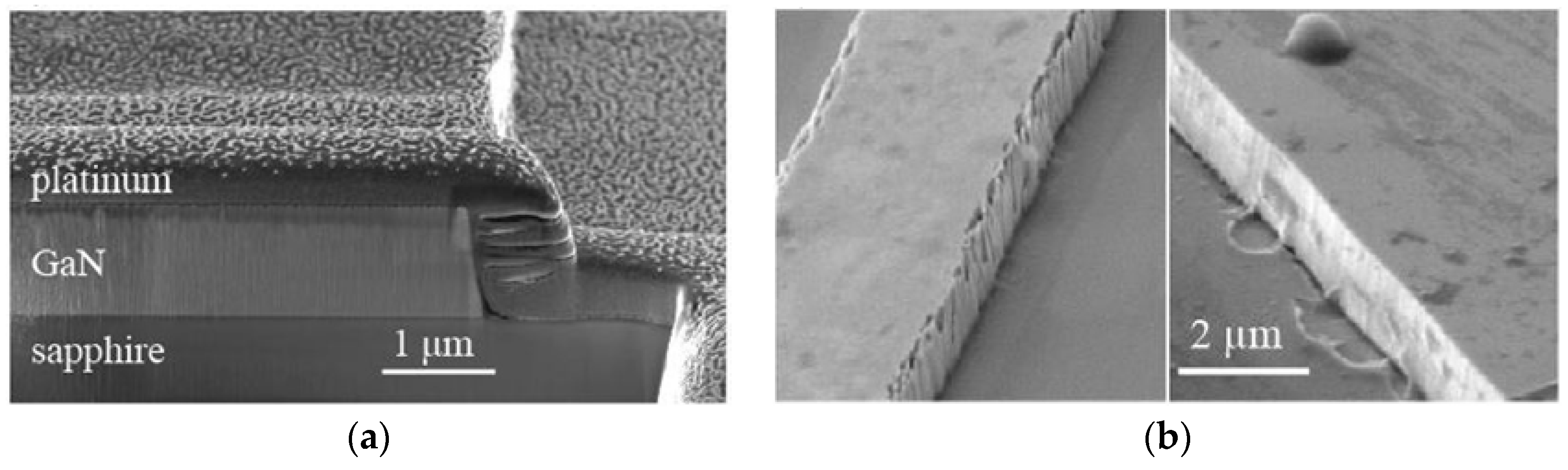
Figure 2.
(a) Top view of the experimental setup with the end-fire coupling system. Femtosecond pulses of vertical polarization are adequately attenuated with a neutral density (ND) filter and coupled into GaN waveguides with their polar axis vertical. The out-coupled signal is vertically polarized and is filtered with a shortpass filter and the SHG signal is analyzed with the spectrograph connected to the photon counting camera. (b) Side-view of the end-fire coupling system. Coupling lenses and a sample holder are mounted on xyz translation stages, which enable precise positioning of the focal point of the laser beam onto the front facet of the waveguide.
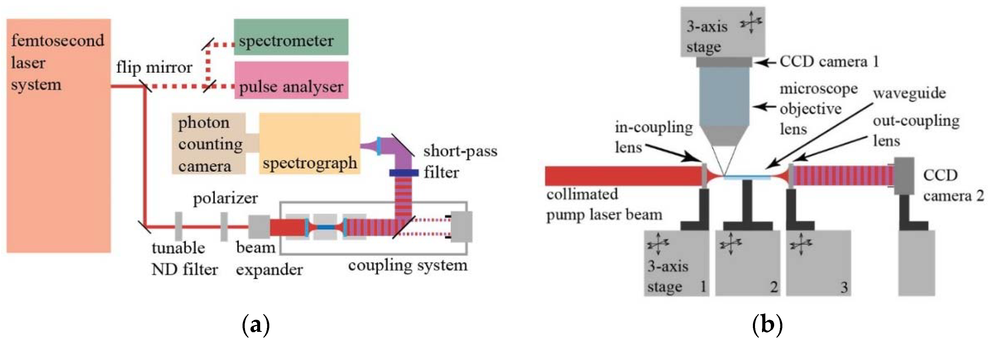
Figure 3.
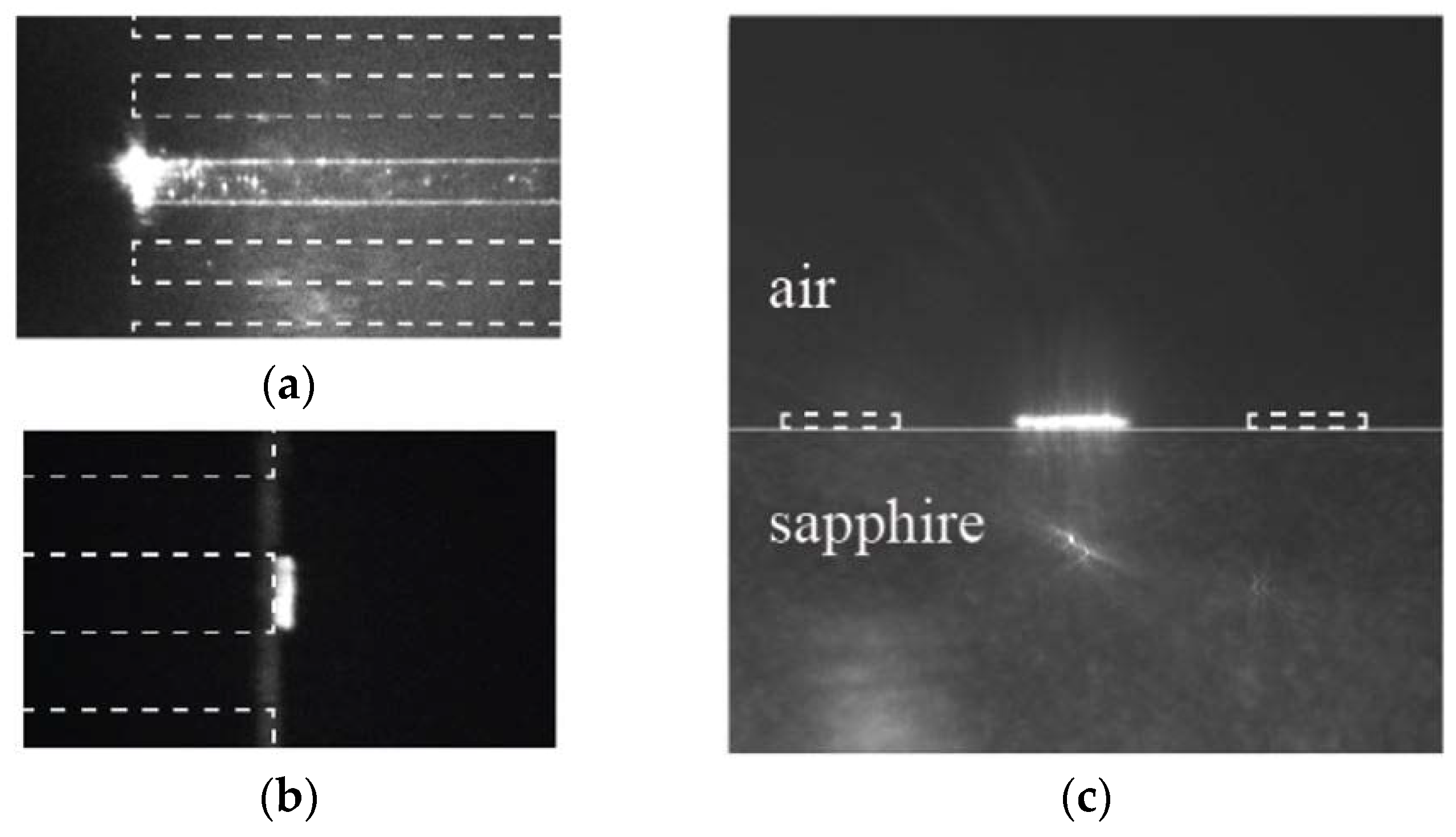
Light propagation observed by CCD camera 1, shown in Figure 2b, mounted above the sample: (a) At in-coupling and (b) out-coupling positions. (c) Out-coupling recorded by CCD camera 2, shown in Figure 2b. White dashed lines represent waveguide positions where they are not easily seen. Note that all waveguides have a stripe width of 10 μm.
Figure 3.
Light propagation observed by CCD camera 1, shown in Figure 2b, mounted above the sample: (a) At in-coupling and (b) out-coupling positions. (c) Out-coupling recorded by CCD camera 2, shown in Figure 2b. White dashed lines represent waveguide positions where they are not easily seen. Note that all waveguides have a stripe width of 10 μm.

Figure 4.
SHG signal counts (blue) measured in 10 min from a 1 mm long GaN waveguide at different central wavelengths of the pump (green). Note the different wavelength scale for the pump and SHG.
Figure 4.
SHG signal counts (blue) measured in 10 min from a 1 mm long GaN waveguide at different central wavelengths of the pump (green). Note the different wavelength scale for the pump and SHG.

Figure 5.
(a) Dispersions of the effective refractive indices for the pump (dashed blue lines) and SHG (green lines) waveguide modes in a GaN waveguide with a thickness of 1140 nm. Dashed black lines represent the dispersions of the extraordinary refractive indices of bulk GaN, given in Equation (4) [20] and sapphire [26]. The red circle indicates the modal-dispersion phase matching (MDPM) interaction, which is responsible for the measured SHG signal. (b) Overlapping of the electric field distributions, , for two possible waveguide interactions responsible for the measured SHG signal. The waveguide modes at the pump wave are presented with blue lines, modes at the SHG wavelength with green lines, while squares of pump modes are presented with black dotted lines.


Table 1.
Comparison of different values of overlap integrals , where λ is the pump wavelength. The calculations shown are for possible modal-dispersion phase matching (MDPM) interactions indicated in Figure 5a.
Table 1.
Comparison of different values of overlap integrals , where λ is the pump wavelength. The calculations shown are for possible modal-dispersion phase matching (MDPM) interactions indicated in Figure 5a.
| p = 0, q = 4, λ = 900 nm | 6.34 × 10⁻⁴ |
| p = 1, q = 5, λ = 900 nm | 1.81 × 10⁻⁵ |
| p = 0, q = 5, λ = 815 nm | 1.44 × 10⁻⁶ |
| p = 1, q = 6, λ = 810 nm | 1.83 × 10⁻³ |
| p = 2, q = 7, λ = 825 nm | 9.10 × 10⁻⁵ |
© 2018 by the authors. Licensee MDPI, Basel, Switzerland. This article is an open access article distributed under the terms and conditions of the Creative Commons Attribution (CC BY) license (http://creativecommons.org/licenses/by/4.0/).
Share and Cite
MDPI and ACS Style
Rigler, M.; Troha, T.; Guo, W.; Kirste, R.; Bryan, I.; Collazo, R.; Sitar, Z.; Zgonik, M. Second-Harmonic Generation of Blue Light in GaN Waveguides. Appl. Sci. 2018, 8, 1218. https://doi.org/10.3390/app8081218
AMA Style
Rigler M, Troha T, Guo W, Kirste R, Bryan I, Collazo R, Sitar Z, Zgonik M. Second-Harmonic Generation of Blue Light in GaN Waveguides. Applied Sciences. 2018; 8(8):1218. https://doi.org/10.3390/app8081218
Chicago/Turabian StyleRigler, Martin, Tinkara Troha, Wei Guo, Ronny Kirste, Isaac Bryan, Ramon Collazo, Zlatko Sitar, and Marko Zgonik. 2018. "Second-Harmonic Generation of Blue Light in GaN Waveguides" Applied Sciences 8, no. 8: 1218. https://doi.org/10.3390/app8081218
Note that from the first issue of 2016, this journal uses article numbers instead of page numbers. See further details here.