Agustin de Betancourt’s Mechanical Dredger in the Port of Kronstadt: Analysis through Computer-Aided Engineering


1
Department of Engineering Graphics, Design and Projects, University of Jaén, Campus de las Lagunillas, s/n, 23071 Jaén, Spain
2
Engineering Graphics and Industrial Archaeology Research Group, University of Jaén, Campus de las Lagunillas, s/n, 23071 Jaén, Spain
*
Author to whom correspondence should be addressed.
Appl. Sci. 2018, 8(8), 1338; https://doi.org/10.3390/app8081338
Submission received: 17 July 2018
/
Revised: 3 August 2018
/
Accepted: 7 August 2018
/
Published: 10 August 2018
(This article belongs to the Section Mechanical Engineering)
Abstract
:This article analyzes the first self-propelled floating dredging machine designed and executed by Agustín de Betancourt in 1810 to dredge the port of Kronstadt (Russia). With this objective, a study of computer-aided engineering (CAE) has been carried out using the parametric software Autodesk Inventor Professional, consisting of a static analysis using the finite element method, of the 3D model which is reliable under operating conditions. The results have shown that the system of inertia drums proposed by Betancourt manages to dissipate the tensions between the different elements, locating the highest stresses in the links of the bucket rosary, specifically at the point of contact between links. Similarly, the maximum displacements and the greatest deformations (always associated with these points of greater stress), are far from reaching the limits of breakage of the material used in its construction, as well as the safety coefficient of the invention, confirming that the mechanism was oversized, as was generally the case at the time. This analysis highlights the talent of the Spanish engineer and his mastery of mechanics, in an invention, the first of its kind worldwide, which served the Russian Empire for many years.

1. Introduction
The mechanical dredger of the Kronstadt port (Russia) was the first self-propelled floating dredging machine in history [1]. This statement is sufficient to understand the relevance of its inventor, the Spanish engineer Agustín de Betancourt, who was one of the greatest references in the engineering of the first industrial revolution. Betancourt, through his works and publications, provided a legacy to civil and industrial engineering that contributed to the industrial progress of the time. In addition, his academic activity, his contribution to theoretical mechanics and his memories and essays meant that many other engineers in Europe followed his steps. The imprint of the famous Spaniard can still be seen today, but his activity as an engineer is little known. This article attempts to highlight the talent of the engineer from the point of view of engineering, focusing on the projected mechanical dredger which remained in service for close to 10 years.
After his formative period in Madrid, Paris and London, Agustín de Betancourt returned to Spain to take over the Royal Cabinet of Machines of Buen Retiro. This, together with the orders to carry out a project of an engineering school and other orders for inspection and advice, showed the great confidence that the Secretaries of State, Floridablanca and Aranda, had deposited in him. In the summer of 1792 he was encouraged to work on a machine to clean the sea beds of the ports of Cadiz and Cartagena, a task entrusted to him by the Ministry of the Navy. In October of 1792, he was appointed director of the Royal Cabinet and it was arranged that his residence was in the Palace of Buen Retiro itself, but the Count of Aranda presented his resignation in November of that year and Manuel Godoy became the plenipotentiary minister of King Carlos IV. This unexpected change of protagonists completely truncated the progress of his plans, since Godoy’s ill disposition towards the engineer was known. The school project ceased to be valid and the Real Gabinete de Máquinas was reduced to a museum of models [2], and in turn the Ministry of the Navy rejected the idea of the dredge for the ports of Cádiz or Cartagena.
The plans for the dredging machine lay forgotten among the engineer’s files for three decades. However, in 1808 Betancourt’s being in Paris presented a new opportunity. Napoleon had begun the war in Spain and the engineer was already seeking to leave Paris by accepting the offer of Tsar Alexander I to work in Russia. During the interim months, his friend Gaspard de Prony was appointed Commissioner for the inspection of the ports of Ancona, Venice and Pola. In particular, the situation of the port of Venice, clogged by mud, had to be resolved, and aware of the difficulties of his friend Betancourt offered him the project of the dredger and he sent it to the French government. The memory “Proposition pour établir une nouvelle machine pour creuser le canal et le Port de Venise” is preserved today [3], but was never put into practice [4].
The memory echoes the problem of the port of Venice and details the volume of mud needed to extract. It therefore estimates the resources and costs of the action with the available means, concluding the low efficiency of the measure. Finally, it details the solution of using a double self-propelled mechanical dredger by means of its double-action steam engine installed on a boat, underlining the advantages of ingenuity (speed, ability to work at different depths, cost, etc.). Betancourt indicates that the dredger (bucket rosary) is of the Louis type, therefore not the original, but it was the system of propulsion and transmission of movement of the dredge. The memory dated 15 May 1808 ends with eight plans, all signed by the Spanish engineer.
Betancourt said goodbye to Paris in October 1808, and on 30 October was already installed in St. Petersburg with his family, where he remained until the end of his life. Not two years had passed when the opportunity was presented again to start up the planned dredge, and this time the project would come to fruition. The port of Kronstadt, a strategic naval base located in the bay of Finland, had problems similar to those of the port of Venice due to the sand that accumulated in the seabed. The experience acquired in helping Prony was very recent, and for a couple of months he drew new plans and adjusted and adapted the project of the floating dredger for the port of Venice to the characteristics of the new site. Of the dredger of Kronstadt, only the sheets drawn up by Betancourt have reached our days, where the important modifications with respect to the French project are appreciated. Finally, the invention was published in August 1812 and worked without interruption until 1820, satisfactorily covering all expectations [5].
The objective of this research is to carry out a static analysis [6] using the finite element method [7] under operating conditions of the dredging machine in order to determine if it was well dimensioned and functional. It therefore follows the research line of other studies carried out by the authors on other historical inventions of Agustín de Betancourt [8,9,10].
2. Materials and Methods
The dredging machine installed on a 33 m long vessel is a very large and surprisingly complex machine for the time it was built, and was driven by the double-action steam engine designed by Betancourt.
The website of the digital Betancourt project [11] of the Fundación Canaria Orotava de Historia de la Ciencia containts the material used in this study [12]. Previously, reference has been made to the memory that Agustín de Betancourt wrote for Prony for the project of a machine for dredging the port of Venice in 1807 (Figure 1), as well as the illustrated sheets of the machine used to dredge the port of Kronstadt (Figure 2). Specifically, 16 pages refer to the two dredging machines mentioned and there is a descriptive memory of 10 pages. The information in this file concerning the dredge project for the port of Venice (1807) was provided for digitalization by the National School of Bridges and Roads of the ParisTech University, and the dossier concerning the dredger of the port of Kronstadt (1810) was assigned by the Communication Roads Library of the University of St. Petersburg.
For the Computer-Aided Engineering (CAE) study of the dredger, essentially the eight sheets of the dredger Kronstadt port were used, but for the understanding of some of the parts and their proper functioning the dredge sheets designed for the port of Venice and the memory of said invention were also used.
As for the sheets of the dredger of the port of Kronstadt, the first is an elevation (front view) of the steam-propelled dredging ship. The second is a profile view of the same with the dredger running. The third is a top view of the ship. The fourth is especially interesting, since it is the same profile view but with a longitudinal section of the boat where you can see the propulsion system of the dredging machine (Betancourt’s double-action steam engine). The rest of the sheets are detailed views of the pieces that make up the dredging machine and the spoon for collecting major obstacles from the seabed.
These sheets appear without scale (as in the rest of the engineer’s inventions) as the functional purpose of the plan prevails over the metric purpose, because at the time there were no standardized materials nor did it make sense to talk about adjustments between pieces since these were hand crafted. Therefore, in order to obtain the 3D model, it was necessary to start from an a priori scale, from which corrections were made as the results suggested that some parts were not sufficiently dimensioned. Despite not having detailed planimetric information, it is noteworthy that the drawing has an almost perfect proportionality.
Regarding the methodology used to obtain a 3D digital model, Autodesk Inventor Professional [13], computer-aided design parametric software developed by Autodesk, was used to obtain an accurate and reliable digital restitution of the dredging machine.
Below, the process followed in the three-dimensional modeling and its geometric documentation is shown in detail, explaining the restrictions applied and the assumptions adopted so that the design of the historical invention was coherent.
2.1. Computer-Aided Design (CAD)
This research is based on the 3D model obtained authentically thanks to the use of Autodesk Inventor Professional software (release 2016, Autodesk, Inc., San Rafael, CA, USA), a process explained in detail in another article [14]. The CAD techniques used provide a realistic model in which each material is perfectly defined, as well as its geometry and relationship with the objects with which it comes into contact.
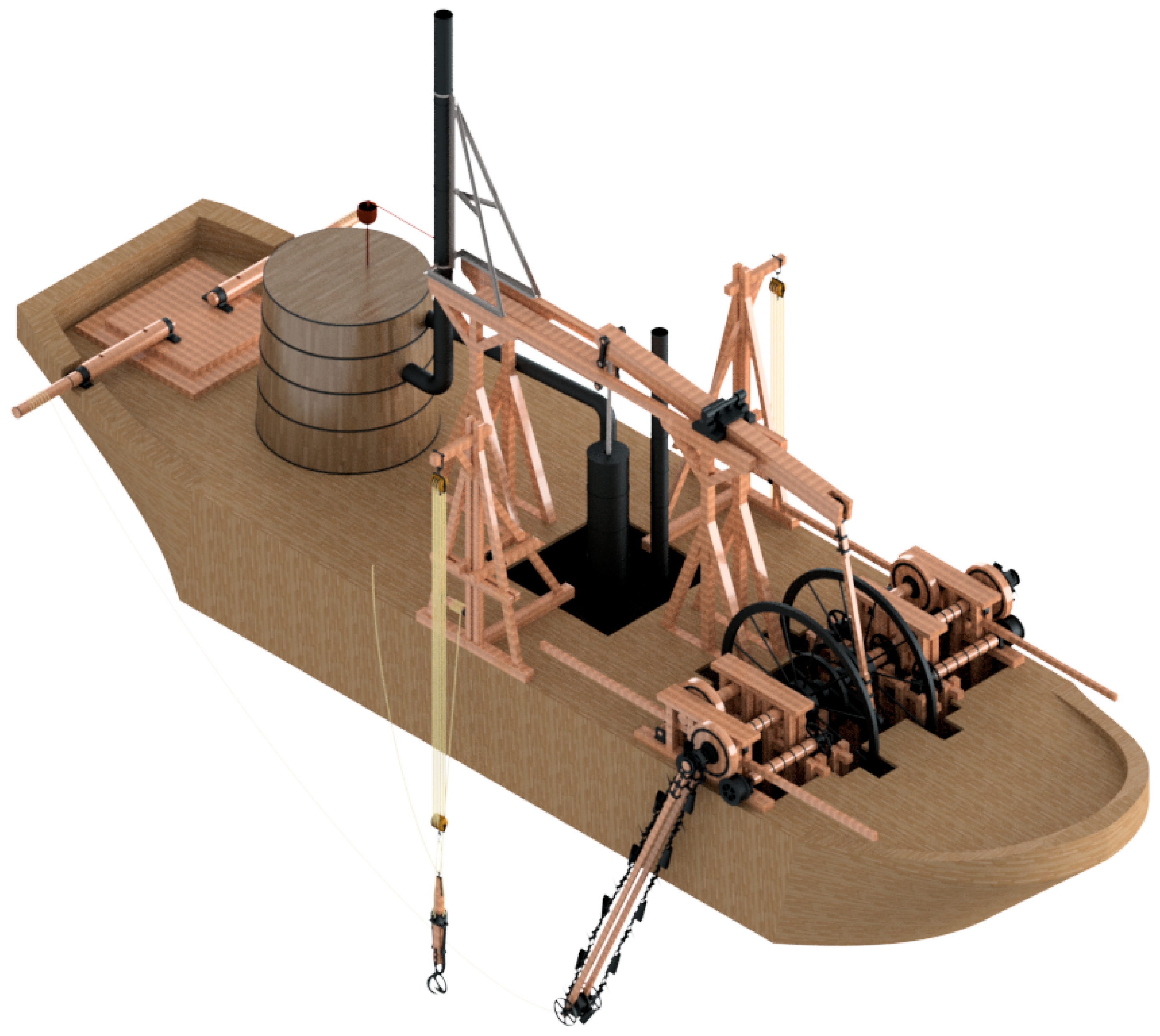
Figure 3 shows the result of the digital restitution of the 3D model of the Kronstadt port dredger with all its elements in detail. Similarly, in Figure 4 an assembly plan appears with a list of marks of the different elements, in which all accessory components have been eliminated.
The mechanical dredger of the port of Kronstadt is installed on a boat of 33 m in length in which a series of elements can be highlighted. At the stern stands the steam engine boiler. This steam engine is of double action (invented by Betancourt himself following James Watt), which aims to move the complex system of transmissions that appear in the bow of the ship, ending in two rosaries of buckets or dredge buckets (this rosary system is not original to Betancourt). On the sides of the steam engine there also appear two cranes finished in clamps (spoons). Finally, in the stern there are also two horizontal axes whose purpose was to position the dredger at the desired height.
Below, the operation of the machine will be described based on Figure 4. The other subsystems are not shown because the object of study of the article resides in the dredge. The driving element, a double-action steam engine improved by Betancourt from that of James Watt, also has great interest in its originality and efficiency, but a careful study of it would be the subject of another complete article. The remaining subsystems (cranes and axes) are not original elements, and the engineer makes use of them because they were common at the time.
The dredger, as mentioned before, is a Louis-type bucket dredger; this is what Betancourt himself says in the memory he writes for the machine of the port of Venice. The purpose of the engineered dredge system is not only the removal of mud and soil from the bottom of the ports, but also the displacement of the ship. In other words, the buckets not only remove earth from the bottom but also function as a ‘caterpillar’ system, facilitating the movement of the ship.
The drive moves the piston coupled to the joint between two rockers (4). The main rocker (2), the one closest to the dredger, is connected at one end to a connecting rod (26). The connecting rod connects to a crankshaft (25) that moves two large flywheels of inertia (5). The flywheel is solidly joined to a main shaft (22), so that the crankshaft and connecting rod manage to transform the swinging motion into another one of rotation (Figure 5).
The main shaft of the dredge has in turn a toothed crown (straight gear) in its middle area that meshes with two auxiliary crowns (6), attached to the frame of the mechanism (1), and which in turn engage with respective toothed crowns (23) joined to other two axes.
The main shaft has in its distal zone a driving wheel (20) that transmits the movement to the friction drum (7) of the dredge shaft (24). The dredge shaft moves the drive pinion of the dredge (28). The ratio of turns between the flywheel and the drive pinion is inversely proportional to the ratio between the diameters of the drive wheel and the inertia drum (720 mm/1493 mm), which means that for each turn of the flywheel inertia the pinion turns halfway.
The contact of these axes through the driving wheel and friction drum has several objectives; to support the shaft that supports the dredge mechanism, reduce the inertia of the shaft and easily separate the dredge shaft and the main shaft which causes the dredge to stop.
As mentioned before, the main shaft moves two parallel secondary axes (21 and 10) of similar characteristics and does so thanks to the set of straight gears. These are two simple axes that have at their ends a crown (23) that meshes with the auxiliary crowns (6), and a wheel (20) that serves as support for the friction drum.
A second shaft (9) similar to that of the dredger is arranged between the main axle and the secondary axle but does not transmit movement to any pinion. This axle appears tied with a rope on the sheets. The purpose of this parallel axle is to increase or decrease the friction with the drive wheels by accelerating or braking the speed of the dredge.
The dredger is arranged as a rosary of buckets or cleaning buckets (11). The union of these buckets is achieved through a chain of alternate iron links (15, 16) that mesh with the pinion of the dredge shaft (28). This shaft has pyramidal trunk teeth which facilitate correct contact with the chain. Every three links there is a bucket (11) or a cleaning hook (12), also in an alternating manner. The dredge rosary remains taut thanks to a double axle or rail (17) terminating in a secondary pinion (14) at the end of it. In addition, for the dredger rail to move easily through the seabed there are also two metal wheels (13) of 750 mm in diameter on the sides of the secondary gear that do not interfere with the movement of the dredge.
This system offered an advantage from the mechanical point of view, since in the event of colliding with an element that blocked the dredger, as the drum of the dredge shaft comes into contact only with the drive wheel if it abruptly stops turning the drum the wheel keeps sliding as there is no gear in between. Thus, the mechanism suffers much less since there is no possibility of breakage.
As previously mentioned, the Betancourt machine has an original propulsion system: the system designed for maneuvering and positioning the dredge (Figure 5). It does not move like other steam boats using shovels but by the very movement of the bucket rosary of the dredger.
Thus, the ship’s government should allow independent play with the speeds of the port or starboard buckets, and this was performed fundamentally with the brakes and the friction wheels mentioned above.
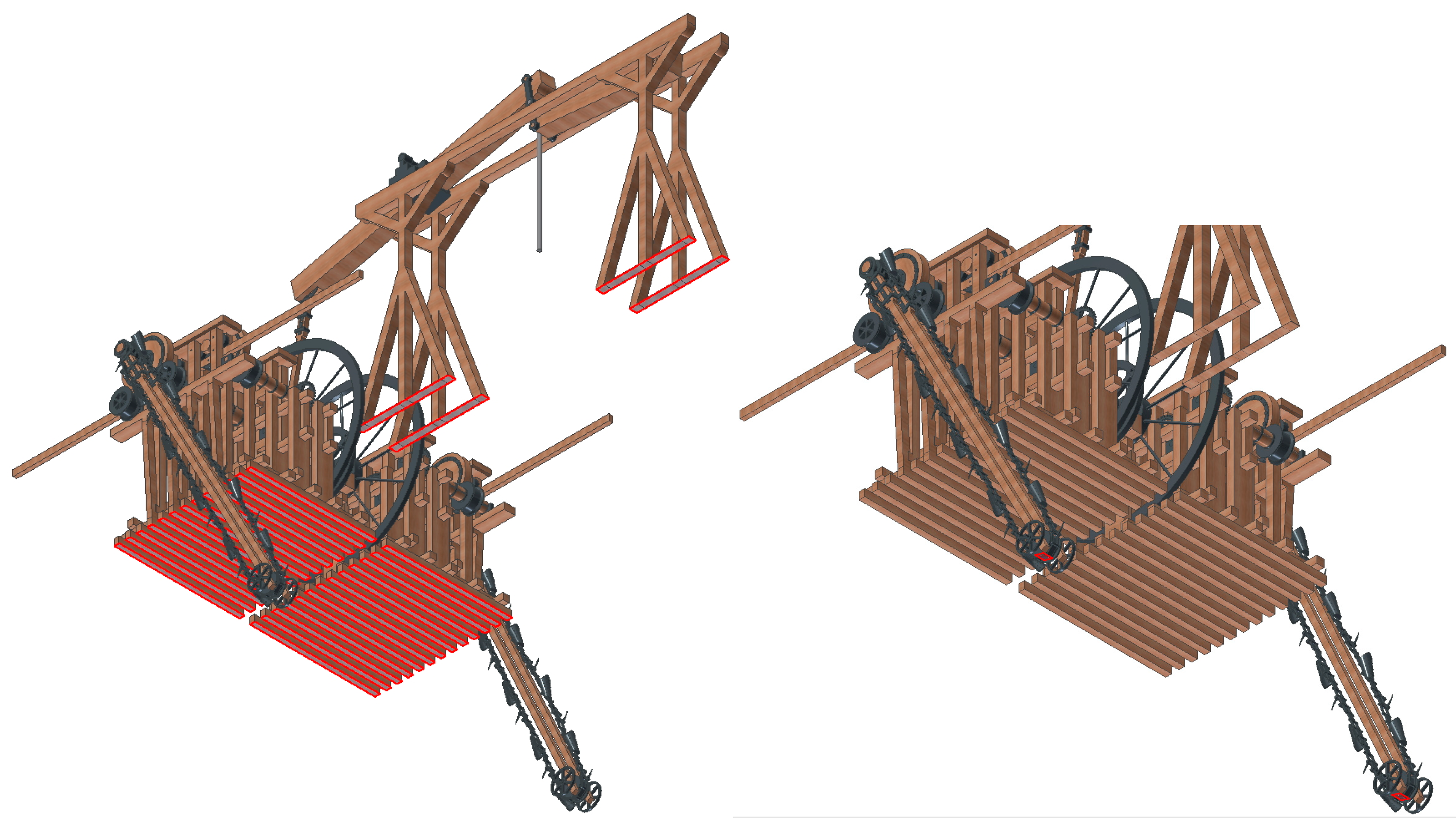
The speed control system of the dredge was exercised by means of two bars (Figure 6 and Figure 7). These bars, at the end of which there was a bearing, operated as a lever. When pushed downwards, the bearing of the lever came into contact with the friction axle (9), the one whose movement hindered the rope, or with the shaft of the dredge (24). That contact lifts the friction drum from the drive wheels, so the shaft immediately stops rolling. When lifting the work lever (Figure 6), the dredge shaft comes into contact with the main one, and the bucket rosary begins to move. If the braking lever is lifted (Figure 7) the friction shaft, which is obstructed by a rope, hinders the movement of the axles, which can stop the movement of the bucket rosary and even the crankshaft itself. Figure 8 shows the position of working and braking levers raised to slow down the movement of the mechanism. The ship and the dredging speed were controlled by means of four operators that manipulated two levers to starboard and two to port.
2.2. Computer-Aided Engineering (CAE)
2.2.1. Pre-Processing
In order to carry out a computer-aided engineering study of the mechanical dredger, it is necessary to determine which elements are structural and which are accessories in order to simplify the model, thus avoiding high computational requirements. Without this previous step, the simulation would be slowed down excessively due to the excessive number of elements that a priori intervene in the calculation. Therefore, by simplifying and eliminating the accessory elements of the simulation the analysis is facilitated and the results of the analysis are not affected.
- In the present study, the ship that acts as support for the dredge has been eliminated. Simulating an object over another that floats is a complicated task, but the dimensions of the ship and the working conditions in a port area mean that the ship can be dispensed with. For this reason, the support of the structure will be characterized in such a way that it receives the forces exerted on the dredge.
- Secondly, the steam engine with the boiler and its support structures are also excluded from the analysis. The only element that will be respected is the cylinder piston of the machine since it is the driving element of the entire dredge system.
- The cranes and axes that position the dredger at different depths are also excluded from the analysis, since they do not exert any structural influence either.
- Finally, the supporting elements of the rocker arm, the connecting rod-crankshaft system and the supports of each of the two dredges are respected.
Once the dredge system has been isolated, all the elements of the dredge have been respected, as can be seen in Figure 9.
2.2.2. Assignment of Materials
The next step is to assign a material to each element. In principle, this step should be carried out in the 3D modeling of the dredger, but in many cases it must be modified or added when assembling. Autodesk Inventor Professional will only proceed with the analysis of the 3D model if all the parts of the assembly have a defined material. In the mechanism that is being analyzed, all the elements can be correctly defined from the library of materials provided by the software itself, based on those that could have been used at the time since neither the memory nor the sheets specify the material of each element. Metal elements can be distinguished from those of wood, but it is not known specifically which materials were used. For the parts made of wood, oak was chosen, abundant in the northern European countries, and for the metallic, cast iron.
When importing materials from the software library, the elements to which the material is assigned acquire their physical properties. Thus, the cast iron used in the metal parts has an isotropic behavior (it behaves in the same way in all its directions), and its main physical properties are: Young’s modulus (210,000 MPa), Poisson’s coefficient (0.30), density (7150 kg/m3) and breaking stress (758 MPa). On the other hand, the wooden elements are made of oak and their physical properties are different in each direction, that is to say that it is an orthotropic material. Wood works with better structural properties when it goes in the direction of the grain. In the other two orthogonal directions, the physical limits are more reduced, and therefore the work is more limited. When assigning materials to the piece, it is important that the main axis of the piece goes in the direction of the grain: Young’s modulus (210,000 MPa), Poisson’s coefficient (0.30), density (760 kg/m3) and breaking stress (41 MPa).
2.2.3. Boundary Conditions
After assigning the material to each of the elements and simplifying the model, the boundary conditions of the elements that have a support function must be defined. Autodesk Inventor Professional does not define the supports in the classic way such as built-in, articulated, mobile or roller, but it does so by defining the degree of freedom of each component of the support.
Therefore, we first proceed to define the surfaces that does not have any degree of freedom. Thus, the surfaces that are screwed to the ship (fundamentally the supports of the structures) are defined (Figure 10 Left), but also, in order to simulate the most unfavorable situation for the structure, the contact surface between the link and the tooth of the lower crown of the dredge is to be fixed. This situation simulates the stop of the dredge when encountering an obstacle (Figure 10 Right).
Secondly, the joints are defined. The surfaces defined in this way are free to rotate with respect to an axis. In principle, the contact between surfaces of the elements that participate in the articulated area has been defined when making the model, so it is not necessary to ensure that the element behaves like a joint. In any regard, the fixed joints of the rockers that are in the supports are defined and will receive substantial stresses (Figure 11).
Finally, in order to finish defining the boundary conditions, the contacts between the elements must be established. If the assembly of the parts has been performed correctly, Autodesk Inventor Professional will automatically detect the contact between nearby surfaces, and only in places where the geometry is more complex will it be necessary to define the contacts manually. In the present study, it has been necessary to define two types of contact manually: the contact between the friction drums and some bearings that served as support (Figure 12), and the contact between the link and the surface of the pinion that facilitates the turn (Figure 13).
2.2.4. Forces Applied
The penultimate step before proceeding with static analysis is to determine the forces applied to the mechanism. There are three large groups of actions that will intervene in the mechanism; they are as follows.
First, the force of gravity, which will affect all parts of the mechanism. Autodesk Inventor Professional makes it easy to define this action. However, for gravity to be a generic force and not applied at a specific point, it must be defined by indicating an intensity and a specific direction. Usually, if axes have been defined in standard mode the vertical axis will be Z and the intensity will be −9.81 m/s2 so that it takes the negative direction of the Z axis. In this way, the software automatically represents the force of gravity as a vector applied at the center of gravity of the mechanism (Figure 14).
The second group of actions is the one determined by the weight of the sand carried by each of the buckets. In order to obtain a stress study that determines the structural capacity of the mechanism, it is necessary to carry it out in the most unfavorable situation. This situation occurs when the buckets of the dredger are completely loaded with sand. Due to their disposition only, those that are ascending towards the ship are full of sand, so a point load is applied to the bottom of the bucket in five of the 10 buckets, since the others are supposed to be empty when descending (Figure 15).
In order to simplify the calculation water, wet sand and submerged sand that would lead to different loads will not be taken into consideration, so if the load is considered without wetting and without pushing, the action will be compensated will hardly change with respect to the real situation.
Assuming that the sand has a dry density (δ) of 1600 kg/m3, and knowing that the maximum volume of a bucket (V) is 0.011 m3, its weight can be calculated:
Finally, the last action to consider has to do with the force exerted by the steam engine on the axis of the piston, which is responsible for all the movement of the machine. In the face of static analysis, the maximum force that the steam engine is capable of transmitting to the cylinder piston will be taken. In order to calculate this, it has been necessary to examine studies of the double-action steam engine of the time.
In the 19th century, Thomas Tredgold, an English civil engineer, wrote a small treatise on the application of Watt’s double-action steam engine to navigation [15]. Because of its similarity to that of Betancourt, this method has been adopted to calculate the steam power of the engine. Thus, Tredgold quantifies the machine’s losses in order to calculate its useful work. If the strength of the steam in the boiler is taken as 1, and the losses due to non-condensed steam are disregarded, the other losses will be:
1st The force produced by the movement of the steam when entering the cylinder: 0.007
2nd Cooling in the cylinder and in the pipes: 0.016
3rd Piston friction and losses: 0.125
4th The force necessary to expel the steam: 0.007
5th The force required to open and close the valves, raise the injection water and overcome the friction of the axles: 0.063
6th The loss that comes from intercepting the steam before the end of the course: 0.100
7th The force needed to move the air pump: 0.050
The sum of all of these is 0.368. Therefore, the difference with respect to the unit is 0.632. Furthermore, it is known that the steam pressure in a coal boiler was generally 900 mm Hg, the temperature of the non-condensed steam 50 °C, and the pressure absorbed by this non-condensed steam about 100 mm Hg. Thus, the resulting pressure (σ) will be:
which expressed in units of the International System is equivalent to a pressure of 6300 kg/m2 approximately.
On the other hand, the pressure exerted by water vapor on the piston is defined by Pascal’s expression:
From this formula, the force that the piston transmits to the piston can be cleared, taking into account the dimensions of the piston surface (S).
Figure 16 shows the force of 41,489 N exerted by the steam engine on the piston that moves the dredge mechanism.
2.2.5. Meshing
The discretization or meshing is the previous step to the static analysis. For this purpose, a variable geometry grid will be developed that characterizes the geometry of the mechanical dredger in the most approximate way, so that the size of the mesh grid determines the most reliable approximation to the model.
In principle, the smaller the size of the mesh the better it fits, but this has its opposite in stress analysis, as an excessively small size of the mesh can distort it since, on small surfaces, the contact between elements can cause pressure to grow inappropriately. Because of this we must ensure that the mesh size is appropriate, avoiding the two extremes.
Autodesk Inventor Professional provides an automatic mesh (Figure 17) whose purpose is to adapt itself in the most exact way to the geometry of the model. As is well known, meshing is a geometric simplification which enables us to process the set as a unitary element, dividing it into finite elements that it analyzes later. In the case of the present study, the type of finite element used has been the tetrahedron.
The variables by which it is guided are: the average size of the mesh (10% of the length of the element face to be discretized); the minimum size of the mesh (at least 20% of the average size); the modification factor (between adjacent meshes there is no difference greater than 1.5), and the maximum angle of rotation (maximum of 60° between contiguous faces of the mesh). The values taken by default can be modified, but in the present research these values have been respected since they present a geometry very similar to the model and there is, at first sight, no element that presents problems in their discretization.
In theory, as noted above, elements with a more complicated geometry can be meshed manually, determining the length of the mesh. The circular or spherical elements usually pose problems if they are of small size. In these elements it usually happens that, due to the convexity or concavity of the surface, the mesh converges in the interior zones, giving rise to an excessively small reticle that distorts the analysis. In these areas it is necessary to control the size of the mesh in order to avoid convergence. On the other hand, some pieces, due to a complex geometry, suffer distortion because the mesh does not adapt well. In these cases, the mesh size should also be defined, giving a shorter length that fits better to the reality of the piece.
In the present model after a study of automatic meshing, it has been decided to respect the values provided by Autodesk Inventor Professional, since the model apparently has a grid fairly approximate to its geometry. The pieces that present certain convergence in the interior parts, such as the bucket that collects the sand from the bottom, are not determinants at the structural level and therefore, not being subjected to a great solicitation, do not distort the results of the analysis (Figure 18).
In the present model after a study of automatic meshing, it has been decided to respect the values provided by Autodesk Inventor Professional, since the model apparently has a grid fairly approximate to its geometry. The pieces that present certain convergence in the interior parts, such as the bucket that collects the sand from the bottom, are not determinants at the structural level and therefore, not being subjected to a great solicitation, do not distort the results of the analysis (Figure 18).
In terms of finite-element analysis, a convergence criterion is established in order to obtain the results as this analysis is carried out by iterative methods during some cycles. In the present study, the software compares the result with that of the previous cycle, and if the result varies by more than 5% the software re-iterates the analysis. However, if the difference is less than 5% the analysis stops, taking the result as definitive. Autodesk Inventor Professional establishes a maximum number of five iterations, since the time used in each iteration is high.
In this study, taking into account available computer resources, we made the analyses using a grid size of 899,471 elements and 1,696,284 nodes.
3. Results and Discussion
The static analysis of the mechanical dredger of the Kronstadt port shows the distribution of von Mises stresses, displacements, deformations and the safety coefficient throughout the assembly, but before the static analysis a modal frequency analysis was internally performed in order to detect rigid body modes. If this modal frequency analysis would have obtained the first six frequencies equal or close to 0 Hz, then the model would be a mechanism with which it would not make sense to have carried out a static analysis. The frequency obtained were: F1 2.33 Hz, F2 2.34 Hz, F3 2.35 Hz, F4 2.77 Hz, F5 3.10 Hz, and F6 3.10 Hz.
Thus, the von Mises stress distribution (Figure 19) shows that in general the mechanism is subject to low stresses. Autodesk Inventor Professional assigns a scale of colors based on the value of the stress reached, establishing the point with the highest value of the von Mises stress with the color red, and with colors close to blue for the surfaces with the least stress. As can be seen, almost the whole machine works with very low stresses, except the point of maximum stress (89.96 MPa), which corresponds to one of the links of the bucket rosary. This piece is a piece of cast iron, and its breaking point (758 MPa) is well above that value (Figure 20). Therefore, it can be said that in general the joins between links are the areas of the machine under the most stress, but as will be explained later always bear this with little fatigue.
If we examine other areas of the bucket rosary we can see that the link between the rockers is the other point that presents a higher stress, specifically the place where the metal piece that joins both rocker arms with the rocker arm is attached to the dredge. At a certain point the stress is 54.57 MPa, also below the breaking point, although in this case the surrounding materials have a lower threshold and must be analyzed more closely (Figure 21). These joins are those that will present a lower safety coefficient, as will be explained later.
The rest of the elements of the assembly work with very low stresses; therefore, they are not under too mush stress and do not suffer from fatigue. However, one might ask: is it normal for such a complex transmission to present such low stresses? The answer to this question has to do with the use by the engineer of friction drums instead of gears of straight teeth.
A machine like the mechanical dredger runs the risk of being on the seabed with an element that is not capable of moving it. Thus, the chain would suffer a blockage that would affect the transmission. However, as there are no teeth between the axles but rather friction drums, what happens is that these drums roll over one another. Thus, they may heat up or slip, but they will not break. This ingenious procedure avoids a breakage that could become dangerous at sea, since the driving element of the dredger is the bucket rosary itself.
Another parameter that helps to distinguish the structural problems that the dredge can present is the analysis of the safety coefficient. The safety coefficient shows, theoretically, the possible points that may be working above their elastic limit. This parameter is calculated as the quotient between the elasticity limit of the material at a given point and the von Mises stress for that same point, establishing a range of values between 0 and 15. A coefficient equal to or less than 1 indicates that that point is worked over the limit of elasticity, and on the contrary an element is considered well dimensioned when the materials work in a range between 2 and 4. With a value above 6, it is usually considered that an element is oversized, and its dimensions are excessive.
Thus, the point with the lowest safety coefficient is the contact between the right rocker (of the dredger) and the joint between the rockers, a delicate point (already mentioned above) when studying the von Mises stress distribution. Its value is 3.01 and therefore it works adequately below the breaking point (Figure 22). In any case, knowing that it is a point where there is contact between two different materials, and that the environmental conditions facilitate fatigue of the same, it would have been convenient to make the bolts of the rockers with metallic material. Thus, in an aquatic environment such as the sea where the materials suffer even greater wear, it would have been convenient for these bolts to be replaced by a piece of metal that would go through the rocker, and connect it to the cast iron piece of the rocker joints. Betancourt realized this problem in the right rocker. In fact, the rocker shaft is metallic, but he did not have the same opinion when executing its ends. A simple drill in the ends, and the use of a metallic intern of smaller dimensions, would have been enough to solve this possible problem.
The other elements of the assembly have a much higher safety coefficient. If the rockers are removed from the analysis, then the next element with a lower safety coefficient has a value of 6. This concerns the contact of the friction drum with the bearing drum, in particular of the friction drum that is used as a brake. In any case, a safety coeffcient of 6 is far from problematic, as has already been explained.
Similarly, the equivalent deformations of the model show the elements of the assembly that have a greater deformation, which can functionally condition the machine and make it unable to work. The deformation is conditioned by two factors: the length of the element and the solicitation thereof. As can be seen in Figure 23, the deformations in general are almost imperceptible. In addition, Figure 24 shows in detail the place where the deformation is greater, again the bolt where the right rocker arm and rocker arm join, but it is a deformation of 0.12% of the length of the element and therefore almost imperceptable. Therefore, the machine has all the guarantees to operate correctly.
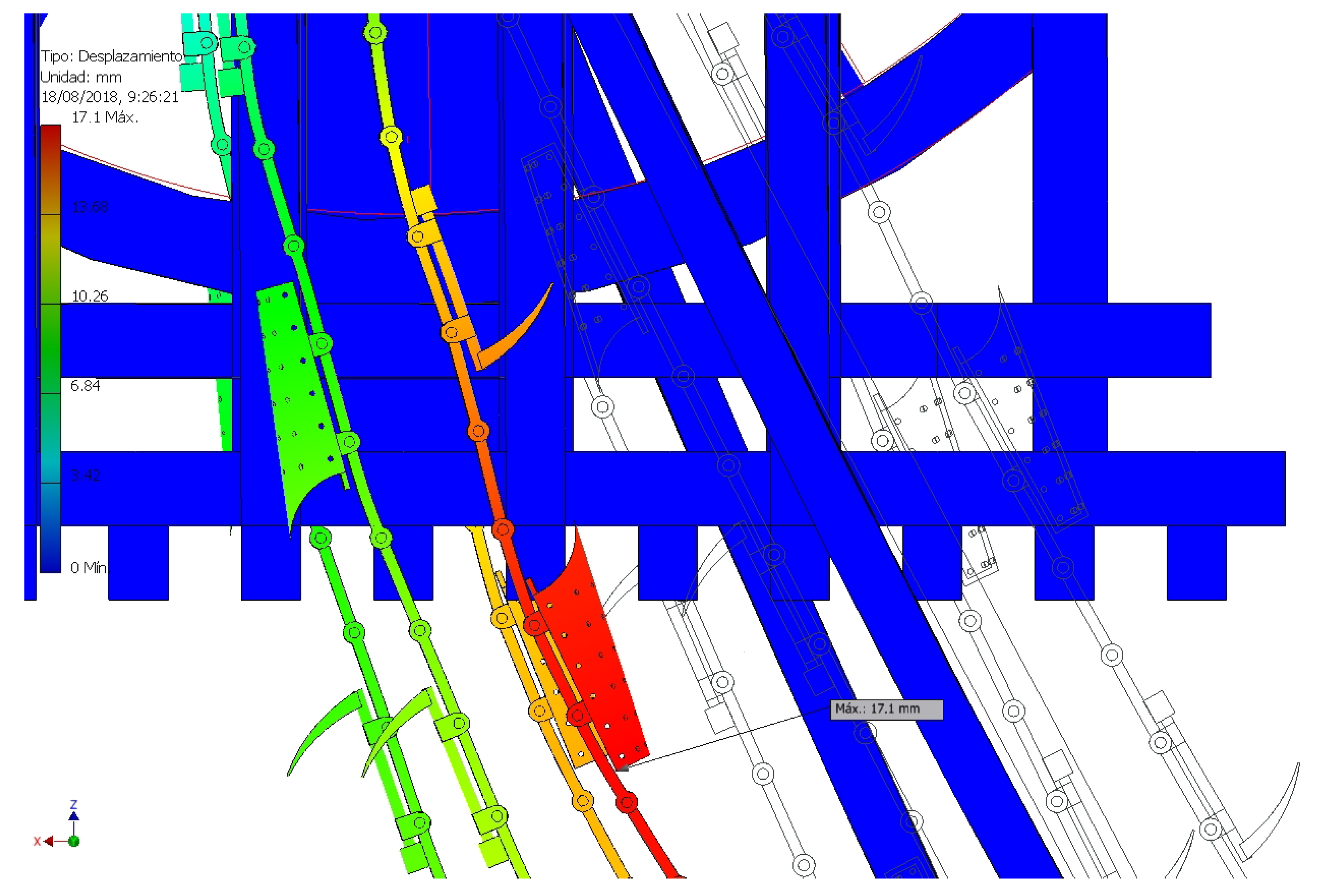
Finally, regarding displacements it can be said that the point of greatest displacement is in the bucket rosary. The maximum displacement does not reach 2 cm (17.10 mm), so in general these are position changes that will not affect the correct operation of the mechanical dredger. In any case this fact, which is logical, underscores the idea that the link chain could work with a little more stress in order to avoid some slack and prevent the links from disengaging from the pinion (Figure 25 and Figure 26).
4. Conclusions
- This paper shows the results of the static analysis carried out on the 3D model of the mechanical dredger at the Kronstadt port, designed and executed by Agustín de Betancourt in 1810, using computer-aided engineering (CAE) techniques thanks to the Autodesk Inventor Professional parametric software.
- It is noteworthy that the stresses are so low, and this is due to the incorporation of friction drums instead of toothed gear. This innovation succededed in reducing the stresses on the contacts of the transmissions, avoiding breakage in the axes, housed in a place of difficult access, and responsible for a function as important as the mobility of the ship.
- In addition, the higher von Mises stresses (89.96 MPa) are located at the junction between the links of the dredger, but since the material used in the bucket rosary is cast iron it is far from reaching its breaking point. The results of the von Mises stresses have confirmed that the mechanical dredger was well dimensioned. In addition, the analysis confirms that all elements work well below their breaking point, so the choice of materials and sizing were correct.
- On the other hand, the point with the lowest safety coefficient (3.01) is the contact between the right rocker (of the dredger) and the joint between the rockers. In addition, the deformations and displacements also have low values (0.12% of the length of the element and 17.10 mm respectively) and confirm the hypothesis that the structure is perfectly dimensioned.
- Nowadays, one could say that the Betancourt machine is oversized and this would lighten the structure in many points, although at the time of its construction there was no study of the resistance of materials and in general, inventions were oversized.
Author Contributions
Formal analysis (J.I.R.-S. and E.D.l.M.-D.l.F.); Funding acquisition (J.I.R.-S.); Investigation (J.I.R.-S.); Methodology (J.I.R.-S. and E.D.l.M.-D.l.F.); Project administration (J.I.R.-S.); Supervision (J.I.R.-S.); Validation (E.D.l.M.-D.l.F.); Visualization (J.I.R.-S.); Writing—original draft (J.I.R.-S. and E.D.l.M.-D.l.F.); Writing—review & editing (J.I.R.-S. and E.D.l.M.-D.l.F.).
Funding
This research was funded by Spanish Ministry of Economic Affairs, Industry and Competitiveness and European Regional Development Fund under grant number HAR2015-63503-P.
Acknowledgments
We sincerely thank the Fundación Canaria Orotava de Historia de la Ciencia for their kindness and permission to use the material from their website.
Conflicts of Interest
The authors declare no conflict of interest.
References
- Mon Vanderostyne, M.; Cohen, M. From hand-drag to jumbo: A millennium of dredging. Terra et Acqua 1999, 77, 1–52. [Google Scholar]
- Rumeu de Armas, A. Fundación y vicisitudes: una empresa técnica de Agustín de Betancourt. In El Real Gabinete de Máquinas del Buen Retiro: Origen; Castalia-Fundación Juanelo Turriano: Madrid, Spain, 1990; ISBN 84-7039-573-4. [Google Scholar]
- Betancourt y Molina, A. Proposition Pour Établir une Nouvelle Machine Pour Creuser le Canal et le Port de Venise. Available online: http://fundacionorotava.es/pynakes/betan_propo_fr_01_1807-LiSe/index.html (accessed on 9 August 2018).
- Sáenz Ridruejo, F. Agustín de Betancourt, en España, Francia, Inglaterra y Rusia. In Libros, Caminos y Días: El Viaje del Ingeniero; Cámara Muñoz, A., Revuelta Pol, B., Eds.; Fundación Juanelo Turriano: Madrid, Spain, 2016; pp. 95–123. ISBN 978-84-942695-9-2. [Google Scholar]
- Cioranescu, A. Agustín de Betancourt: Su Obra Técnica y Científica; Instituto de Estudios Canarios: La Laguna de Tenerife, Spain, 1965. [Google Scholar]
- Hur, D.J.; Know, S. Fatigue analysis of greenhouse structure under wind load and self-weight. Appl. Sci. 2017, 7, 1274. [Google Scholar] [CrossRef]
- Hsia, S.Y.; Chou, Y.T.; Lu, G.F. Analysis of sheet metal tapping screw fabrication using a finite-element method. Appl. Sci. 2016, 6, 300. [Google Scholar] [CrossRef]
- Rojas-Sola, J.I.; De la Morena-de la Fuente, E. Agustin de Betancourt’s wind machine for draining marshy ground: Analysis of its construction through computer-aided engineering. Inf. Constr. 2018, 70, e236. [Google Scholar] [CrossRef]
- Rojas-Sola, J.I.; De la Morena-De la Fuente, E. Agustin de Betancourt’s mill for grinding flint: Analysis by computer-aided engineering. Dyna 2018, 93, 165–169. [Google Scholar] [CrossRef]
- Rojas-Sola, J.I.; De la Morena-de la Fuente, E. Agustín de Betancourt’s plunger lock: analysis of its construction through computer-aided engineering. Inf. Constr. (accepted).
- Proyecto Digital Betancourt. Available online: http://fundacionorotava.es/betancourt (accessed on 9 August 2018).
- Betancourt y Molina, A. Explication D’une Machine Destinée à curer les Ports de mer. Available online: http://fundacionorotava.es/pynakes/lise/betan_expli_fr_01_1808/ (accessed on 27 July 2018).
- Shih, R.A. Parametric Modeling with Autodesk Inventor 2016; SDC Publications: Mission, KS, USA, 2015; ISBN 978-1-58503-971-5. [Google Scholar]
- Rojas-Sola, J.I.; De la Morena-de la Fuente, E. Digital 3D reconstruction of Betancourt’s historical heritage: The dredging machine in the Port of Kronstadt. Virtual Archaeol. Rev. 2018, 9, 44–56. [Google Scholar] [CrossRef]
- Tredgold, T.E. Tratado de las Máquinas de Vapor y de su Aplicación a la Navegación, Minas, Manufacturas etc.; Imprenta de D. León Amarita: Madrid, Spain, 1831. [Google Scholar]
Figure 1.
Front view of the dredge for the port of Venice (courtesy of Fundación Canaria Orotava de Historia de la Ciencia).
Figure 1.
Front view of the dredge for the port of Venice (courtesy of Fundación Canaria Orotava de Historia de la Ciencia).

Figure 2.
Front view of the dredge for the port of Kronstadt (courtesy of Fundación Canaria Orotava de Historia de la Ciencia).
Figure 2.
Front view of the dredge for the port of Kronstadt (courtesy of Fundación Canaria Orotava de Historia de la Ciencia).

Figure 3.
Isometric view of the 3D model.

Figure 4.
Plan of the ensemble with an indicative list of different elements.

Figure 5.
Sequence of movement of the dredge when the piston is in motion (Follow from left to right and top to bottom).
Figure 5.
Sequence of movement of the dredge when the piston is in motion (Follow from left to right and top to bottom).

Figure 6.
Lever raised in working position of the mechanism (the axes that come into play are in blue).
Figure 6.
Lever raised in working position of the mechanism (the axes that come into play are in blue).

Figure 7.
Brake lever for stopping the mechanism raised (the axes in play are in blue).

Figure 8.
Working and braking levers raised to slow down the movement of the mechanism (the axes in play are in blue).
Figure 8.
Working and braking levers raised to slow down the movement of the mechanism (the axes in play are in blue).

Figure 9.
Axonometric view of the simplified dredger system after preprocessing.

Figure 10.
Fixed restrictions: base of the supports (Left) and surface of the link (Right).

Figure 11.
Joints.

Figure 12.
Manual contacts between friction drums and support bearings.

Figure 13.
Manual contacts between the link and the surface of the pinion.

Figure 14.
The force of gravity represented at the center of gravity of the mechanism.

Figure 15.
Forces applied on the buckets (pressure exerted by the sand mass).

Figure 16.
Force exerted by the steam engine on the piston.

Figure 17.
The automatic meshing obtained.

Figure 18.
Bucket of the dredger with a very high mesh density.

Figure 19.
Von Mises stress distribution.

Figure 20.
Maximum von Mises stress reached in a link of the bucket rosary.

Figure 21.
Von Mises stress on the dredger rocker shaft.

Figure 22.
Element with the lowest safety coefficient of the dredge.

Figure 23.
Equivalent deformations of the mechanical dredger.

Figure 24.
Point of maximum deformation.

Figure 25.
Displacement distribution.

Figure 26.
Detail of maximum displacement point.

© 2018 by the authors. Licensee MDPI, Basel, Switzerland. This article is an open access article distributed under the terms and conditions of the Creative Commons Attribution (CC BY) license (http://creativecommons.org/licenses/by/4.0/).
Share and Cite
MDPI and ACS Style
Rojas-Sola, J.I.; De la Morena-De la Fuente, E. Agustin de Betancourt’s Mechanical Dredger in the Port of Kronstadt: Analysis through Computer-Aided Engineering. Appl. Sci. 2018, 8, 1338. https://doi.org/10.3390/app8081338
AMA Style
Rojas-Sola JI, De la Morena-De la Fuente E. Agustin de Betancourt’s Mechanical Dredger in the Port of Kronstadt: Analysis through Computer-Aided Engineering. Applied Sciences. 2018; 8(8):1338. https://doi.org/10.3390/app8081338
Chicago/Turabian StyleRojas-Sola, José Ignacio, and Eduardo De la Morena-De la Fuente. 2018. "Agustin de Betancourt’s Mechanical Dredger in the Port of Kronstadt: Analysis through Computer-Aided Engineering" Applied Sciences 8, no. 8: 1338. https://doi.org/10.3390/app8081338
Note that from the first issue of 2016, this journal uses article numbers instead of page numbers. See further details here.