Research on the Simplified Design of a Centrifugal Compressor Impeller Based on Meridional Plane Modification


School of Mechanical Engineering, Shanghai Jiao Tong University, Shanghai 200240, China
*
Author to whom correspondence should be addressed.
Appl. Sci. 2018, 8(8), 1339; https://doi.org/10.3390/app8081339
Submission received: 7 July 2018
/
Revised: 23 July 2018
/
Accepted: 6 August 2018
/
Published: 10 August 2018
(This article belongs to the Special Issue Radial Turbomachinery Aerodynamics)
Abstract
:This study mainly focuses on investigating the influence of meridional contour of a steam centrifugal compressor on aerodynamic performance. An optimal design method is put forwards, in which the hub-line on the meridional plane is modified and optimized. Based on the data from numerical simulation, aerodynamic characteristics are compared in detail among a prototype and three modified impellers. It is shown that stall margin of the optimized impeller can be enlarged by approximately 50%, though at design point efficiency and pressure ratio is decreased a little bit. Under the working conditions with low flow rate, the optimized impeller exhibits the best performance compared with the prototype and two other impellers. Furthermore, numerical result is validated by the experiment and is matched the measure data very well.
1. Introduction
Aerodynamic and structural design of an impeller are important to the performance of a compressor unit [1]. The design work of a new impeller is mainly focused on the designing of flow passage [2]. Meridional plane design is one of the important parts of the flow passage design. The geometrical profiles of impeller hub and shroud have significant effects on the overall performance of a compressor. This is because the fluid flowing between these two curves not only determines the efficiency of the impeller but also strongly affects the performance of diffuser or volute in downstream [3]. Much progress had been made in last decades [4]. One of the most outstanding works was from Jansen [5], who applied the inverse design methods to the flow passage design in turbomachinery. With recent improvement, the advanced optimization methods have been introduced into the design of meridional profiles. Casey [6] and Wang [7] put forward a method to define the meridional channel by a string of Bezier points. This method based on Bernstein-Bezier polynomial patches had already been a guideline of the parameterization of the meridional plane profile. Borges [8] described a kind of three-dimensional inverse method, by which an imposition of mean swirl was defined as optimization specification throughout the meridional section of the turbomachinery. Benini [9] explored an evolutionary optimization algorithm to optimize meridional geometry, by which the secondary flows across the impeller could been reduced greatly. A numerical method coupled with the optimization design methodology, which was consisted of reaction surface method (RSM), statistical approach and genetic algorithm, was developed to obtain optimized hub and shroud line by Sun [10]. Meanwhile, Cho [11] used an evolutionary algorithm with the help of a Bezier curve to make efficiency higher without the reducing of the pressure ratio. As some extra mechanical constraints, such as the maximum stress and stress distribution, had to be considered in the aerodynamic design, the multidisciplinary and global optimization design methods were presented in resent literature. A software using a through-flow computation with a breeder genetic algorithm had been programmed to acquire the optimization of meridional plane [12]. Mueller [13] presented a multidisciplinary and multi-objective optimization system based on an artificial neural network to improve the performance of the impeller while the mechanical stresses were kept within the limitation.
A traditional meridional profile was usually described by several arc lines, and widely adopted in the most of meridional shape design. It was generally believed that for the shroud line and the hub-line on the meridional plane, the arcs and the smoothed connection among these arcs were beneficial to aerodynamic performance. However, during the process of the manufacturing of a compressor unit, it would take most of time to produce this kind of 3D complex impeller with high cost by a 5-axis machine. In order to save time and cost, welding technology is gradually being used in manufacturing of impellers. It is due to the narrowed shrouded structure that the work of welding blades on the disk is very hard. So, a simplified meridional profile of an impeller is needed urgently to substitute the traditional meridional profile. But, although much improvements on impeller design, such as blade profiles, incidence angle and stagger angle, etc., had been greatly achieved, there was not enough attention on how to simplify the impeller structure to adapt to the welding manufacture.
Therefore, in this paper, a simplified geometrical configuration of the meridional contours is presented, which can simplify the structure of the impeller and be beneficial to the welding manufacture with a little negative effect on the impeller performance.
2. Meridional Shape Design
In this study, an industrial impeller of a steam compressor is used as a prototype. Its design parameters are listed in Table 1.
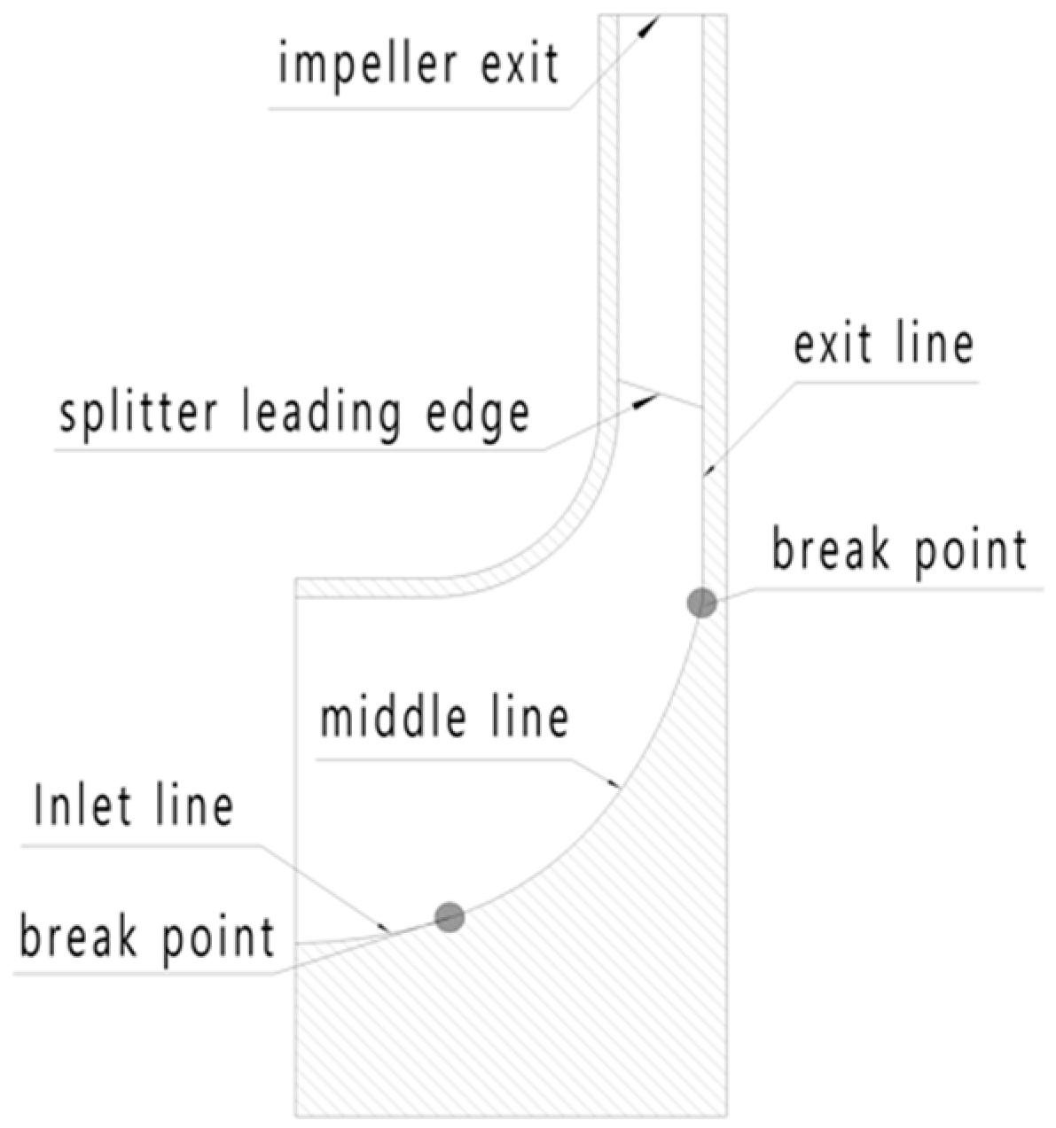
The meridional cross-section of the prototype impeller is shown in Figure 1. The impeller was initially designed with the shrouded structure due to the large outlet diameter, and arc line was used to define the hub and shroud line. Thus, there would have some potential problems during manufacture for the reasons as alluded in the above words.
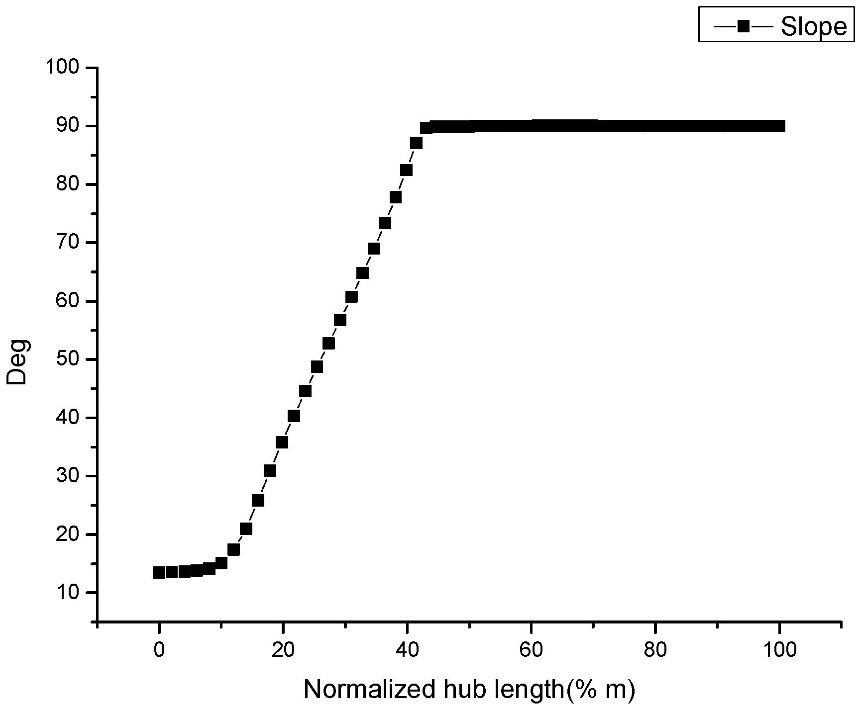
The hub-line is divided into three segments, such as inlet line, middle line and exit line, as shown in Figure 1. The inlet line and middle line are arc line which can be parameterized by Bezier curve method, and exit line is a straight line. These three lines are smoothly connected by two points one by one as shown in the figure. The slope distribution of the hub-line is shown in Figure 2. Figure 2 shows the relationship between slope of the hub-line and axial height of hub-line. These two interrupt points, at which the slope of the hub-line is varied severely, are selected as the break points.
In order to observe the effect of hub-line profile on the machine performance, three modified impellers are introduced in this paper. As shown in Figure 3, the three models are the inlet line changed model (LA), middle line changed model (AL) and both inlet line and middle line changed model (LL). And, other geometrical parameters in these three impellers such as blade angle, back sweep angle, etc., are kept the same as those of the prototype. It is obvious that linear lines are much simpler than the Bezier curve.
3. Numerical Methods
In this study, a commercial software, Numeca FineTM/Turbo [14], is applied to the impeller performance analysis based on a 3-D steady and unsteady compressible finite volume scheme. It is assumed in the simulation that internal flow in impeller is relatively stable three-dimensional viscous compressible turbulent flow. The governing equations are continuous equation including Reynolds-averaged Navier-stokes equation, energy conservation equation, the ideal gas state equation [15]. The governing equations written in a Cartesian frame can be expressed as follows:
where, is flow density, is time, is velocity vector, is external force, is external pressure, is viscous stress, is internal energy, is kinetic energy, is adiabatic index and is temperature. The ideal gas state equation is:
where, is gas constant. Supplementary equations are expressed as:
where, is total energy, is the specific heat at constant volume, is enthalpy of fluid and is entropy. The employed turbulence modelling to consider the compressibility is the Spalart–Allmaras model [16]. The Spalart–Allmaras (S–A) turbulence model contains a set of relatively new single equation, which uses an eddy-viscosity variable , and is combined with speed, precision and stability, the turbulent eddy transport equation. This can be expressed as follows [17]:
where, is production of turbulent viscosity, and are model constants, is molecular kinematic viscosity, is turbulent viscosity, is dynamic viscosity, is cartesian coordinate and is reduction of turbulent viscosity, which happens near the wall.
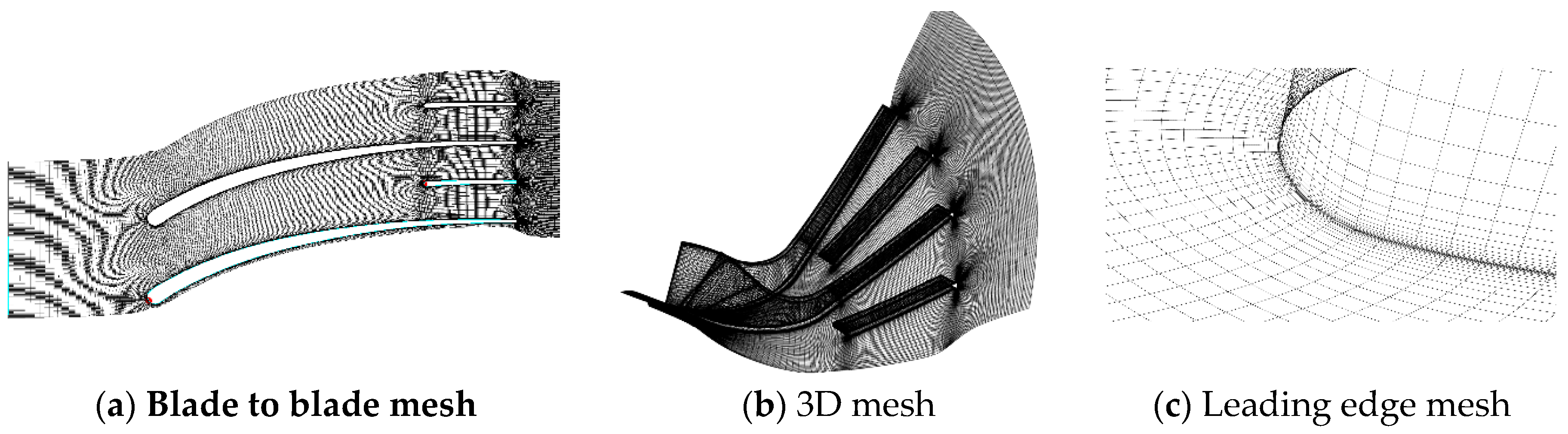
In the upstream and downstream, the computational domain of single flow passage is extended as shown in Figure 4a. The number of grid points for a single passage is around 1,250,000, which is large enough according to the grid independence investigation. y+ is small enough for the S–A turbulence model. The enlarged detail mesh figure around blade leading edge is shown in Figure 4c. A single passage model with periodical boundary conditions is used in steady simulation. Velocity direction, absolute total pressure and total temperature are imposed at the inlet boundary, outlet mass-flow and initial pressure on the outlet boundary. In this study, the working point close to stall condition is figured out by the lowest mass flow, with which the numerical simulation can reach convergent results.
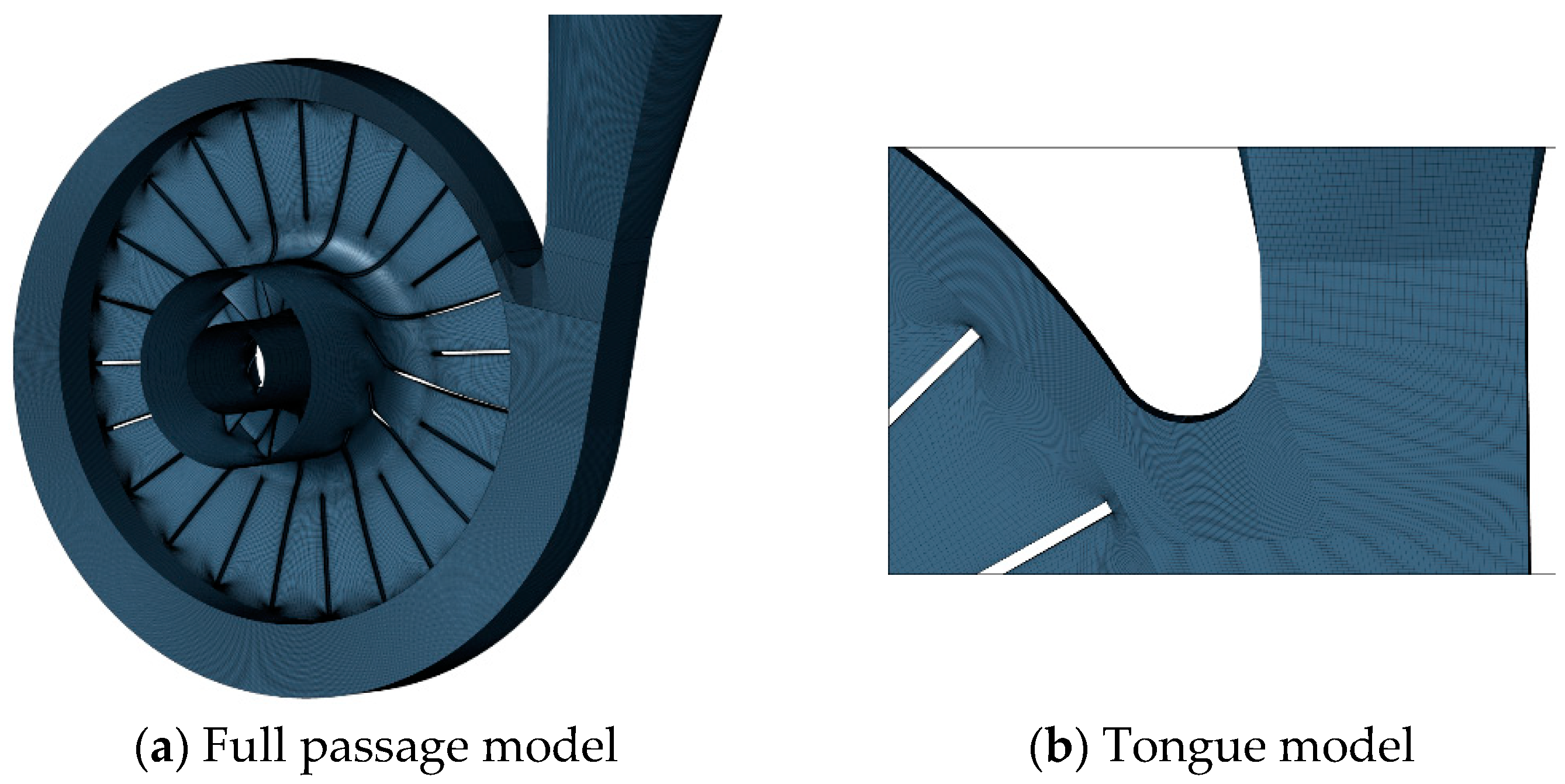
The LL(both inlet line and middle line changed model) impeller is chosen to analyze the steady and unsteady performance with the help of the full passage model. The reason why the LL impeller is chosen to be the optimized impeller will be introduced in the following sections. In the full passage model, the volute with an asymmetrical configuration is considered as shown in Figure 5. The number of the grid points of the whole flow passage model is about 45 million, which is determined by the grid independent research. And, frozen rotor technique is used to deal with the interface between impeller and volute.
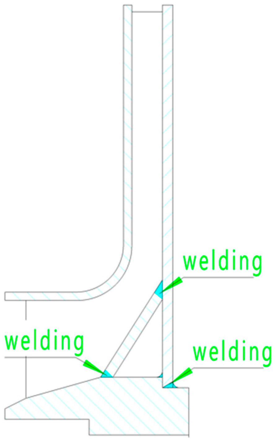
Meanwhile, LL impeller is selected to be the experiment object. Figure 6 shows 2D cross-section of geometric structure of experimental impeller, as is shown, the hub contour is consisted of three straight line. The hub forming is made of three stainless steel plates welded together. There is no requirement to processing whole impeller or the hub with five-axis machine as the conventional impeller. The welding place has been marked out as shown in Figure 6. By this kind of welding technology, not only does processing time and cost cut down, but also the manufacturing of impeller becomes very simple. Furthermore, weight of the impeller can be reduced significantly by the hollow design of the hub, which can be advantageous to the rotor dynamics balance and beneficial to the bearing design.
4. Results and Analysis
4.1. Single Passage Model
4.1.1. Overall Performance
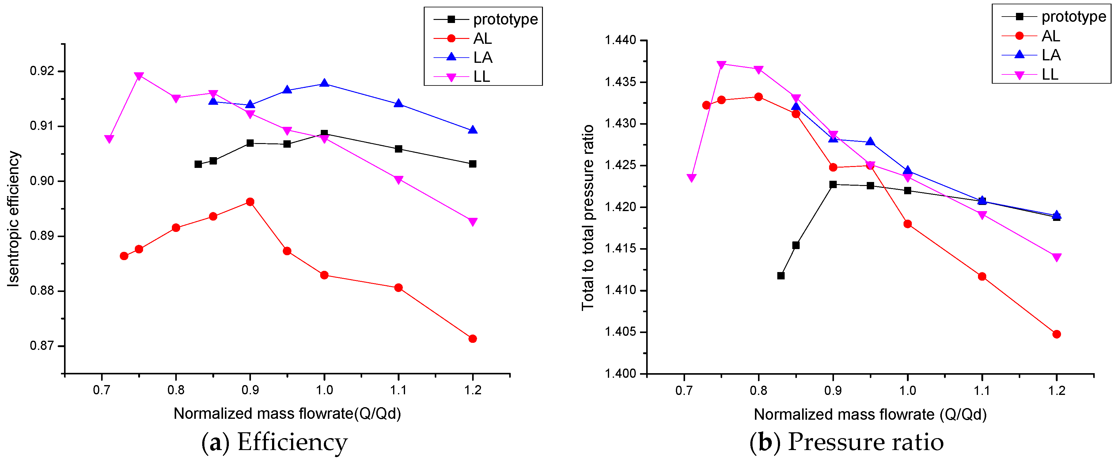
The overall performance of impellers is shown in Figure 7. In this study, the largest mass flow rate (Q/Qd) of all the impellers is selected as 1.2. In fact, it is due to low rotational speed that this kind of impeller has an excellent performance under the working conditions with the large mass rate. So, the choke performance will not be analyzed in the followed words.
In the Figure 7a, at the design point, the LA impeller achieves to the highest efficiency and pressure ratio among four impellers, all the same the AL impeller has the lowest efficiency and pressure ratio. Meanwhile it is found that for the LA and prototype impellers, their peak efficiency points are very close to the design point. But, when the flowrate is decreased, performance of LL impeller appears to be better.
In this research, the compressor characteristics close to stall point are evaluated by the stall margin, as shown in Table 2. The stall margin (SM) is defined as
where, is mass flow rate close to the stall point and the design flow rate. In Table 2, LL impeller has the largest stall margin, which is increase by 50% compared with that of prototype. It means that after the simplifying of the meridional profile, performance at design point of LL impeller is not obviously deteriorated (efficiency and pressure ratio is decreased by about 0.5% compared with that of the prototype as is shown in Figure 7), while in some respects, its off-design performance is improved somewhat.
Though LA impeller presents more excellent capability with large mass rate, performance of the LL impeller seems to be better than that of another three impellers when the machine is slipping into the working conditions with low mass rate.
4.1.2. Meridional Plane
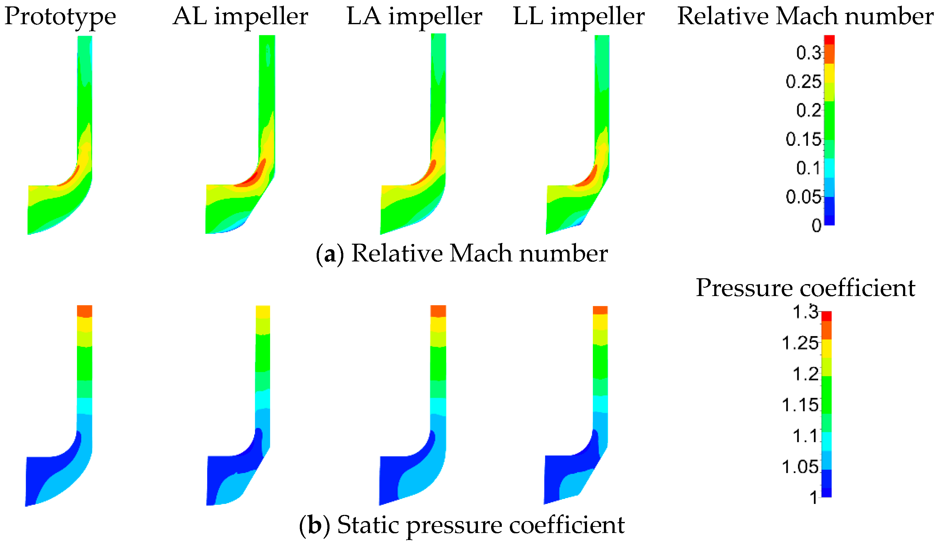
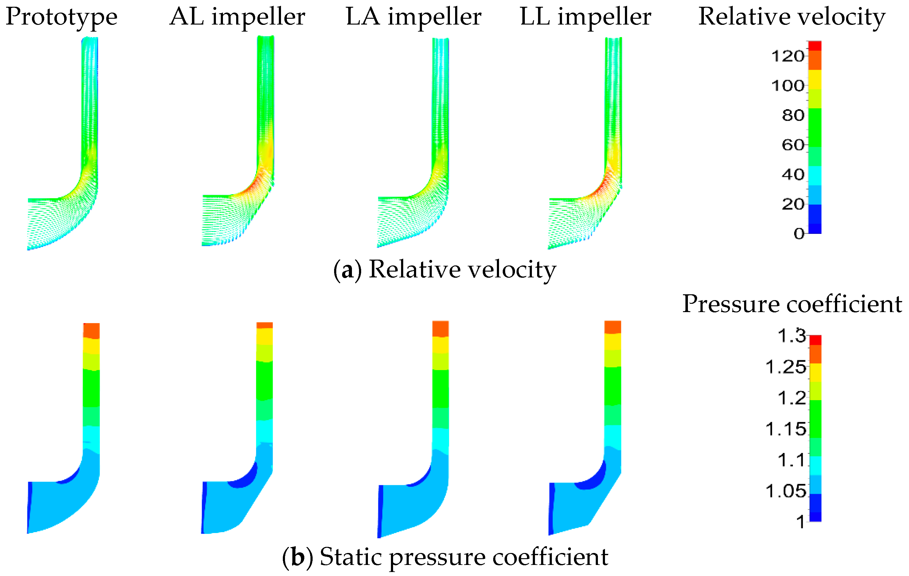
The distributions of relative Mach number and pressure coefficient at the design point are shown in Figure 8. The pressure coefficient shown is defined as
where, is the static pressure and the total pressure at inlet.
In general, the uniform distribution of Mach number and pressure has a positive impact on efficiency and stall margin. But, it is found in Figure 8a that there is a region of high relative Mach number both in AL and LL impeller, which is very close to the turning point of the shroud line. In this region, the pressure is relatively lower, as shown in Figure 8b. So, this kind of nonuniformity of relative Mach number and pressure (shown in Figure 8) probably is one of the negative affects which would lead to lower efficiency of the AL and LL impeller. In contrast, distribution of Mach number and pressure of the prototype and LA impeller is more uniform, which is beneficial to efficiency.
In another words, skin friction loss is another important negative effect to efficiency, which is generated by boundary layers. And the pressure loss coefficient which is resulted from skin friction of solid surfaces can be defined [18] as
where, is the skin friction coefficient, is the averaged relative velocity, is the averaged incidence velocity, is the average length of hub and shroud, and is the outlet hydraulic diameter. The averaged relative velocity of the four impellers is very close to each other as is shown in Figure 7a so that skin friction loss is approximately proportional to . Among these four impellers, of LL impeller is shortest and then the skin friction loss of the LL impeller is smallest.
Furthermore, hub to shroud loading loss, which is produced by secondary flow, can be expressed by the followed equation [18].
where, is the blade curvature and the hub-to-shroud width. It is apparent that the hub-to-shroud width of LL impeller is smallest, which means weaker secondary flows and less loading loss.
Base on above analysis, although the nonuniformity of Mach number and pressure ratio distribution can be observed in the LL impeller, its performance can be made up by the less skin friction loss and loading loss. So, as shown in Figure 8, there is a little performance difference among four impellers at the design point.
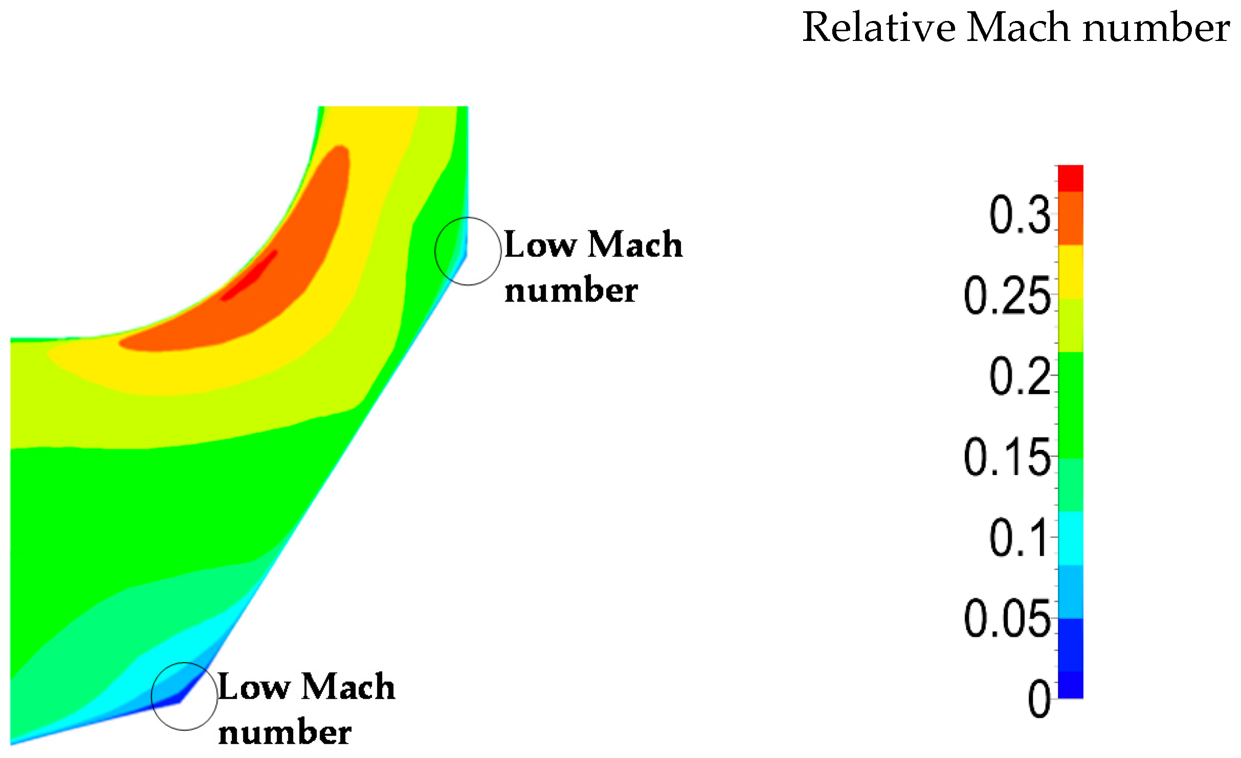
In addition, the connection form with straight line of LL impeller arise two low Mach number regions can be found in the flow field near the break points because of the sharp change of slope, which needed to be concerned in this study. The more clearly pictures of flow situation of LL impeller can be seen in Figure 9. Nevertheless, this low Mach number region is small compared to the whole flow passage, and this phenomenon may be improved by other method of hub separation.
As the machine is operated near the stall point, it is shown in Figure 10 that the meridional relative velocity distribution (Figure 10a) and pressure coefficient distribution (Figure 10b) of four impellers with 0.85 flow rate. It is apparent that there is a high relative velocity domain near the turning area of shroud line of LL impeller, which is beneficial to stall margin.
4.1.3. Blade to Blade Surface
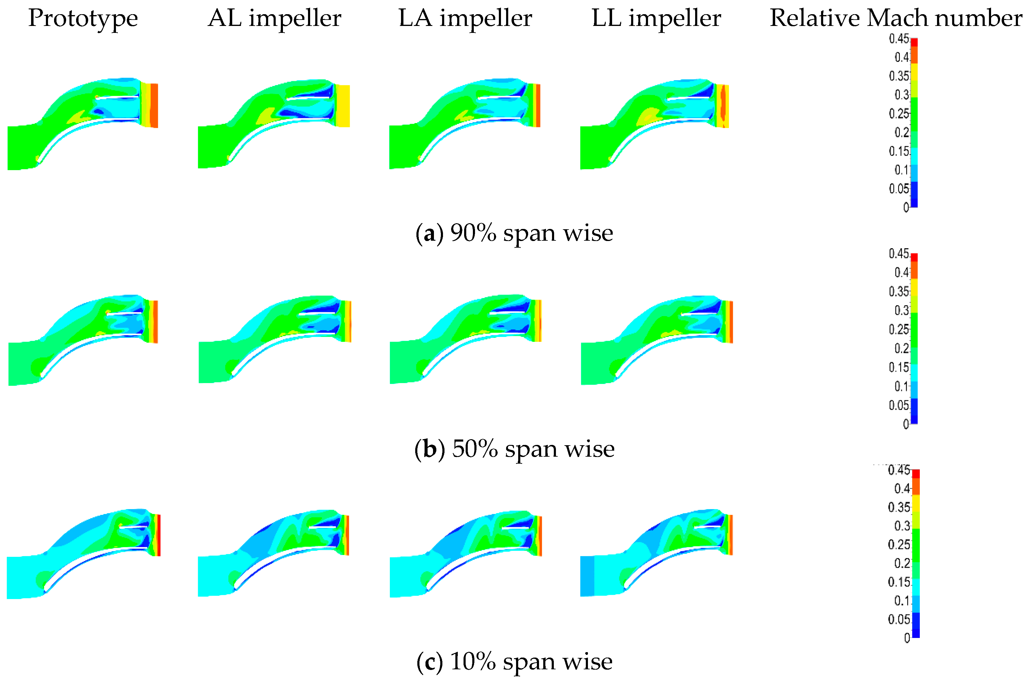
It is shown in Figure 11 that the relative Mach number distribution for three different sections such as span wise 90% (Figure 11a), 50% (Figure 11b), and 10% (Figure 11c) at the design point. For the LL impeller, the maximum Mach number is about 0.45, which is the largest among four impellers, and the region of high Mach number is also the biggest as shown in the Figure 11, which indicates the biggest flowing loss at the design point. Meanwhile, the Mach number near outlet region of the LL impeller appears to be the highest, which indicates lower static pressure ratio as is shown in Figure 7b.
The relative Mach number distribution at 0.85 design flow rate is shown in Figure 12. The highest Mach number can be observed near outlet region in the prototype, which is very different from the performance at the design point. This phenomenon means that the flowing situation of the prototype is closing to its stall point, while the LL impeller still has excellent stall tolerance capability. So, the LL impeller presents the better pressure ratio at the low flow rate than the prototype, which can also be obtained in Figure 6.
4.2. Full Passage
4.2.1. Overall Performance
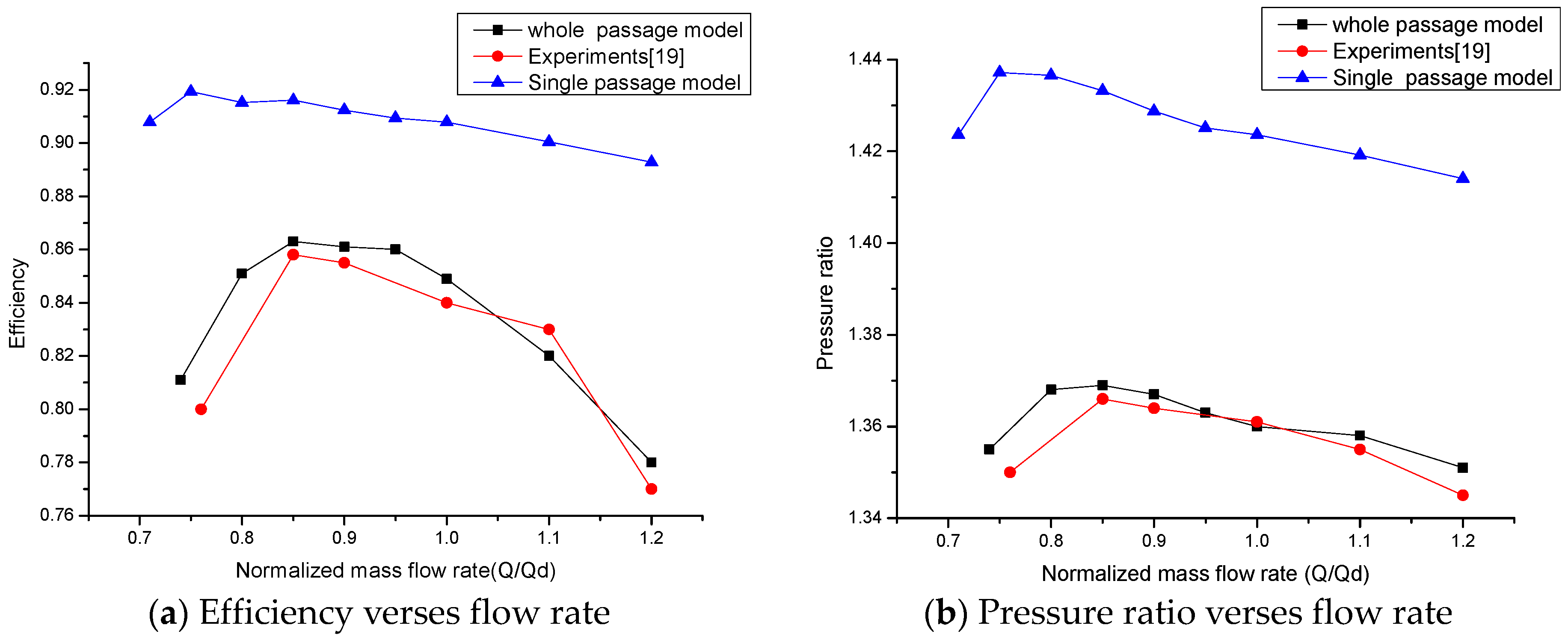
The overall performance of the LL impeller with full passage model is shown in Figure 13. In this figure, the experimental data referred to is from Reference [19]. The calculation result of the full passage model can be matched with experiments very well, while the performance of the single passage model is different from that of the experiment. In the single passage model, the volute is ignored so that flowing loss in volute is not considered.
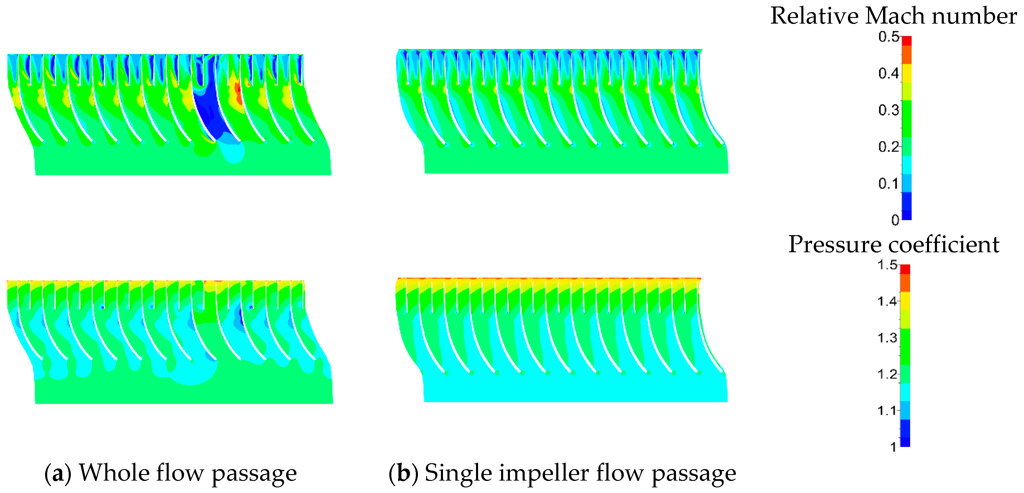
It is shown in Figure 14 that the numerical result comparison of Mach number and pressure coefficient distribution between full passage (Figure 14a) and single passage (Figure 14b) at the design point. It is apparent that the flow pattern of real compressor is unsymmetrical because of the unsymmetrical geometrical structure of the volute.
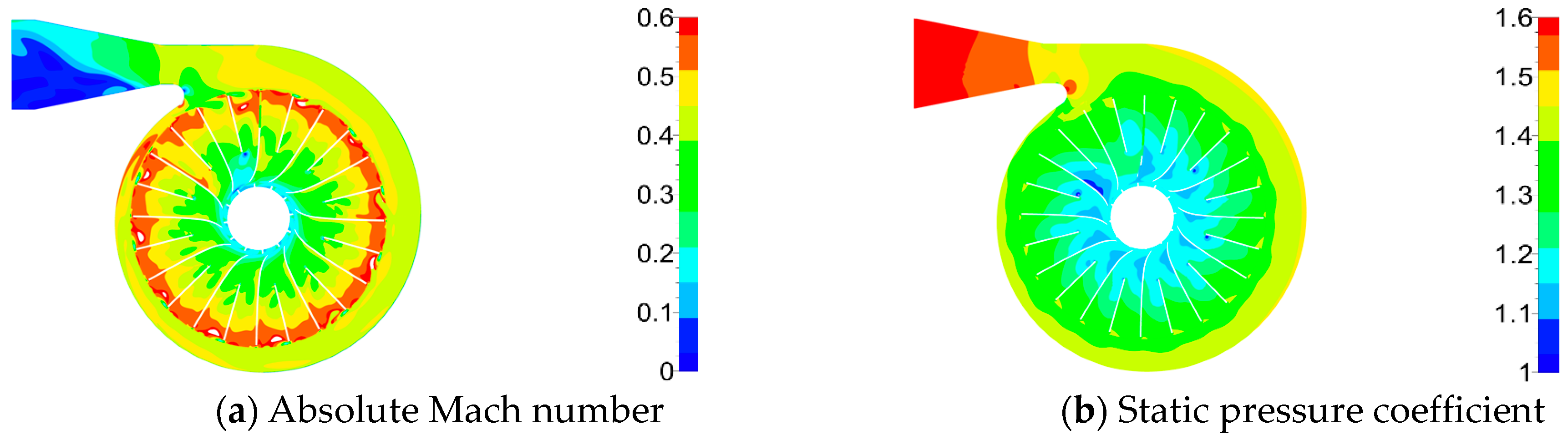
The circumferential flow situation of mid-surface can be seen in Figure 15. The absolute Mach number (Figure 15a) and pressure distribution (Figure 15b) are evidently asymmetric throughout the compressor because of asymmetric structure of volute. There is an obvious high Mach number region in the impeller near the tongue of volute, and the static pressure of this region is also relatively high. It can be inferred that the tongue of volute has significant impact in the nearby flow.
4.2.2. Unsteady Results
All of the above studies are based on steady flow field, but, the impeller is exposed to downstream circumferential unsteady flow, which resulted in blade vibrations and auxiliary noise [20].
The acoustic Strouhal number is employed to characterize unsteady interaction of impeller and volute of compressible flows. This can be defined as follows:
where, is the rotational frequency, the speed of sound estimated with the inlet temperature. represents temporal relationship between rotation speed of impeller and perturbation wave propagation of flow in the impeller. Unsteady effects can be neglected when and the relatively accurate results can be evaluated by steady calculations. While , more accurate results can be obtained through unsteady flow calculations [21]. In this case, is about 0.12 at design point. It implies that the propagation of pressure wave is faster than the rotation speed of the impeller. Therefore, the unsteady numerical investigation, which is focused on the response of pressure distortions imposed by asymmetric geometry of volute, is necessary to be conducted.
Since time-accurate simulation of the unsteady phenomenon, rotational speed and angular displacement between two successive computations should be considered into the numerical time step. The dual-time step (DTS) method was adopted to improve the time marching in unsteady calculation because the adopting of full passage mesh and the highly quality mesh in this study. The unsteady Rotor/Stator interface was set by domain scaling method [22]. The number of angular positions is set to be 20 in one single passage, so there are total of 240 angular positions. The time step can be expressed as equation follows:
where, is the rotor rotation, Nperiods is the number of periodicities and NOFROT is the number of angular positions, so, in this study the time step was , and the steady numerical simulation result is set to be the initial condition of unsteady numerical calculation in the first period.
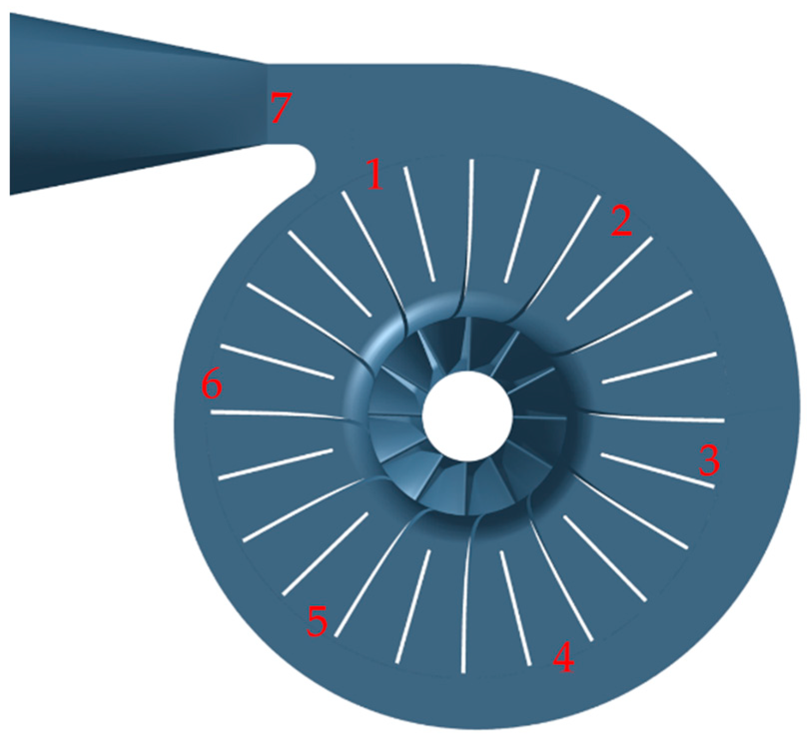
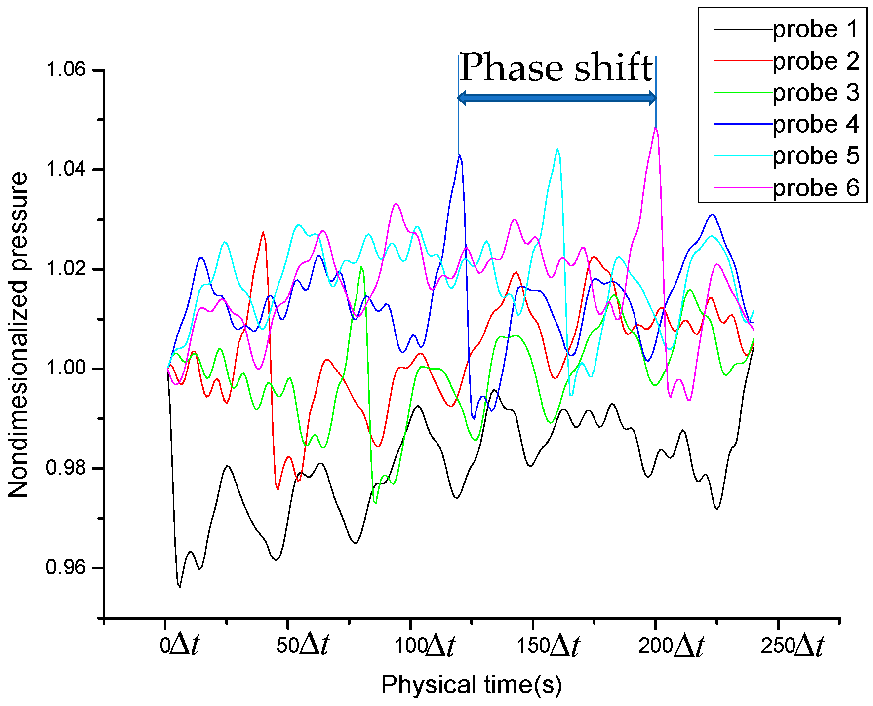
The positions of the seven probes are shown in Figure 16, of which six probes are located at the outlet of impeller and one at the tongue. It is shown in Figure 17 that shows the nondimensionalized static pressure variation of six probes at different locations, respectively. The horizontal ordinate is the physical time which means the rotor need unitary time step () to revolve one angular position, so there are total of 240 because of 240 angular positions. It can be seen that the flow field presented a periodic fluctuation and the shape of curves are different due to the asymmetric configuration of volute. Meanwhile, phase shift between different probe positions is also observed. It is due to the propagation of pressure perturbation from one blade channel to the next.
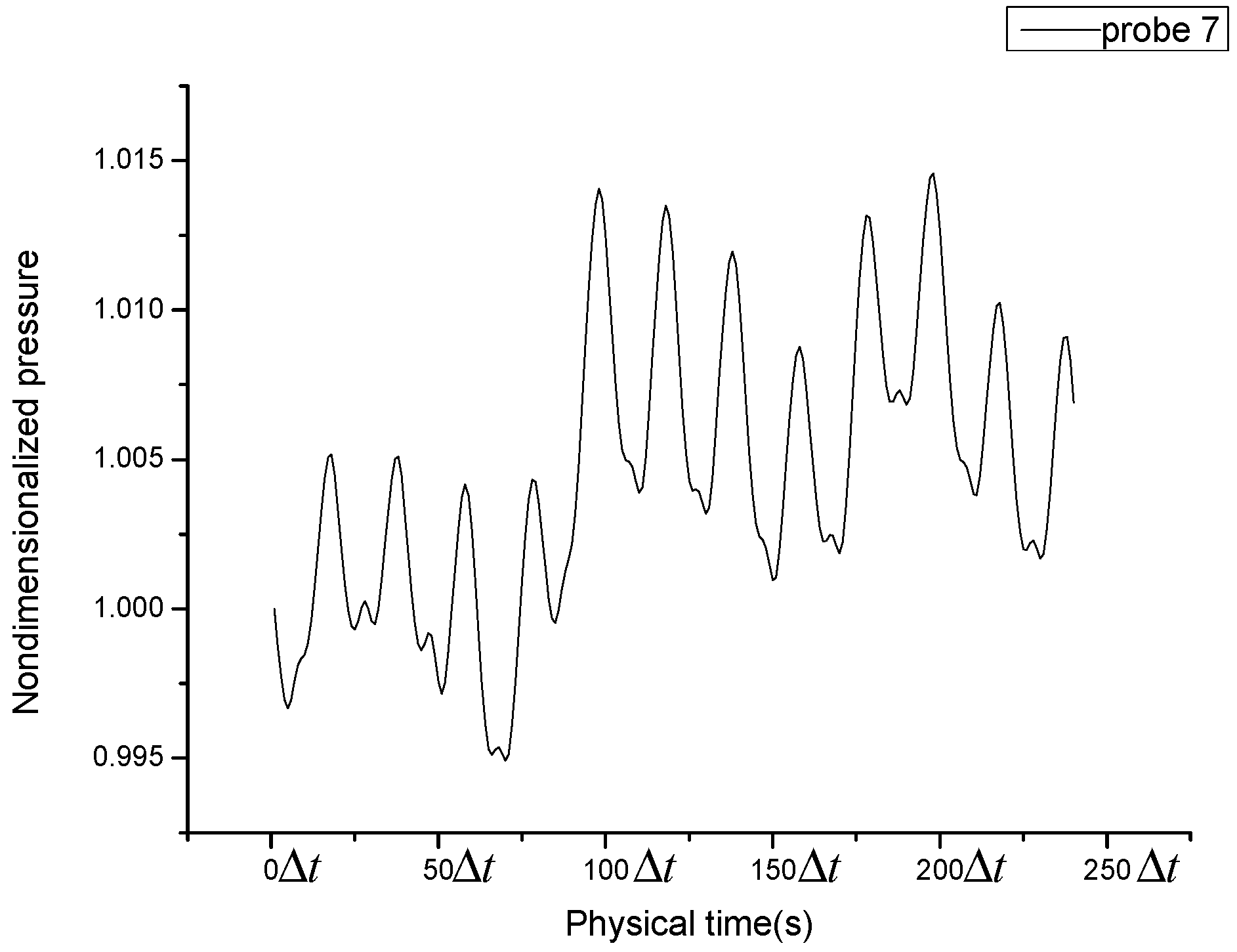
The oscillation of nondimensionalized static pressure of probe 7 at tongue position in a period can be seen in Figure 18. The amplitude of pressure oscillation of tongue is smaller than those of impeller outlet positions, but the frequency of pressure oscillation is bigger. Since the amplitude of pressure oscillation is small, only about 1.5%, the steady numerical simulation result at the tongue position is accurate enough.
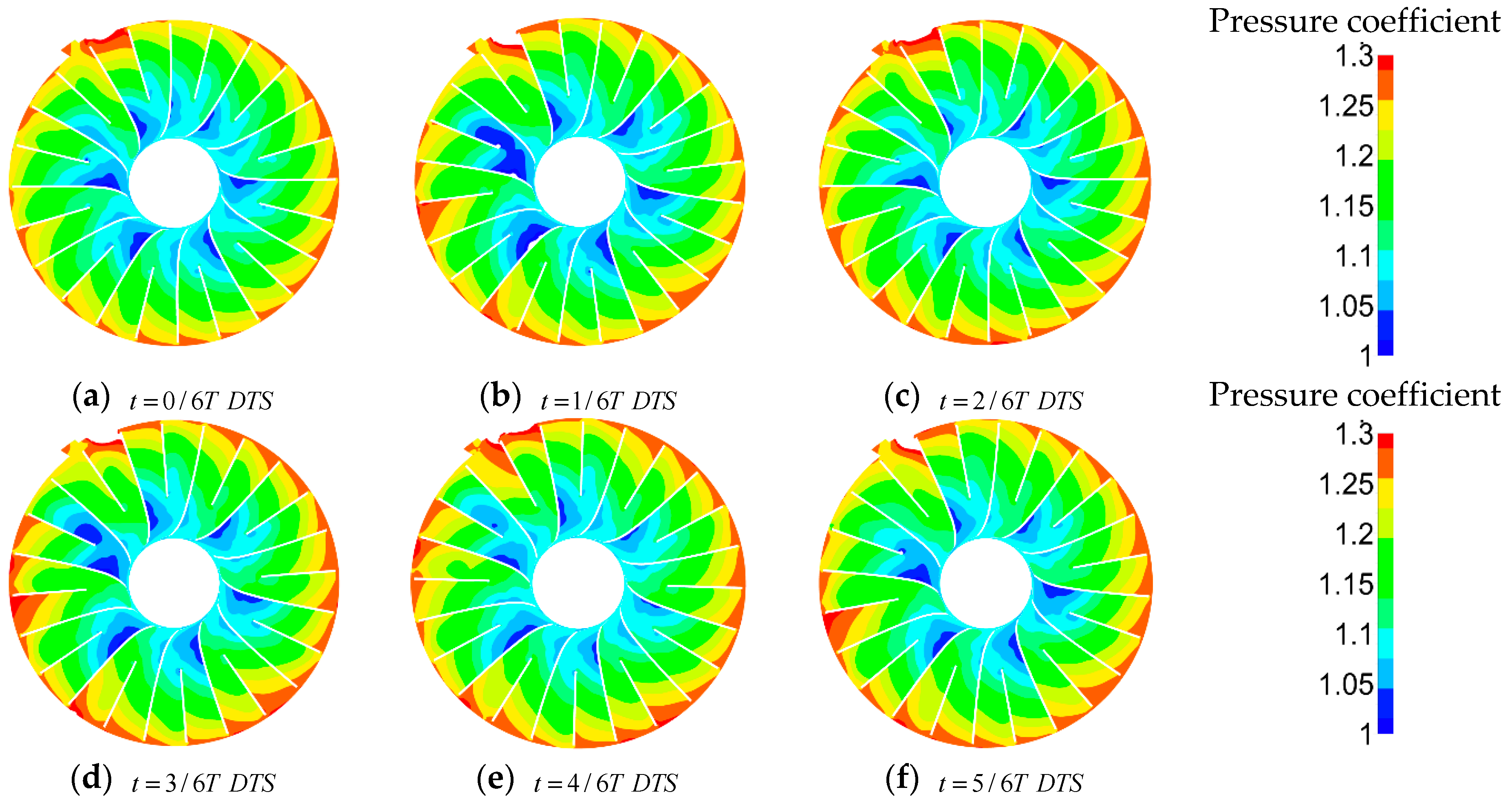
It can be seen in Figure 19 that static pressure distribution at different time steps of 50% radial height near hub in one channel period. When the relative position between impeller and volute is the same as that of steady simulation, the t is adopted as 0. Transformation of static pressure distribution indicates unsteady characteristics, but the influence of which is not obviously. Therefore, the steady numerical simulation result can be used for investigating circumferential asymmetric flow pattern in this study.
5. Discussions
As mentioned above, the performance of compressor can be influenced significantly by the shape of meridional contours. The simplified hub design method is based on the selection of the break points. In this study, the break points are selected when the slope is discontinuous at the points. However, there may be another method to screen the break points, by which more optimized design would be achieved. We plan to discuss in near future research.
Straight lines are applied to describe the hub contours, by which the hub shape is changed, and the area of flow passage is narrowed. It is due to the narrowed passage that the velocity is increased, which is beneficial to the aerodynamic performance sometime especially when machine is operated close to the stall point. However, further research is needed on how to evaluate contribution of the narrowed passage to the stall margin.
In this study, the working medium is water vapor and the rotation speed relatively low so that the compressor performance is stable, and the efficiency and pressure ratio are not changed obviously with the flow rate. However, for another kinds of compressor, the simplified hub contours would give rise to violent change on performance. This is a concern for future research.
Additionally, it is found in all cases that the region of large Mach number is around the leading edge of the splitters. This means that the location of the splitters can also influence the Mach number distribution. It has been proved that optimizing location of the splitter can improve the performance of centrifugal compressor [23], so the splitter design should be considered in the future optimization of impeller.
6. Conclusions
In order to simplify meridional configuration, three impellers are designed with innovative shape. Based on the Computational Fluid Dynamics (CFD) method, detail analysis of steady and unsteady flow field has been carried out with single-passage-model and full-passage-model respectively. Furthermore, the experiment results are used to evaluate the accuracy of CFD results. The conclusions can be drawn as following:
- The processing time and manufacturing cost are reduced because the hub is described by the straight line for the optimized impeller, LL impeller. Moreover, the hollow geometry in the disk may also be beneficial to the rotor dynamic design and bearing design.
- Within the operating range, the prototype impeller has stable performance. Nevertheless, its operating range cannot fully match the industrial requirement. Meanwhile, the simplified impeller, LL impeller, is improved with excellent stall margin as well as its efficiency and pressure ratio are decreased little.
- The calculation result of the full passage model is matched with experiments very well. So, in order to obtain comprehensive performance of a centrifugal compressor, full passage model with volute is necessary to be considered.
- In this case, unsteady calculation is conducted due to 0.12, but the unsteady characteristics of the steam compressor is not obvious. Meanwhile, the amplitude of pressure oscillation around volute tongue is only about 1.5%. Thus, for this case, the steady numerical simulation result is accurate enough to investigate asymmetric circumferential flow pattern.
Author Contributions
Conceptualization, B.Y.; Investigation, H.X.; Software, X.L. and M.S.; Resources, C.G.; Writing-Review & Editing, H.X.
Funding
This research received no external funding.
Conflicts of Interest
The authors declare no conflict of interest.
References
- Shibata, T.; Yagi, M.; Nishida, H.; Kobayashi, H.; Tanaka, M. Performance Improvement of a Centrifugal Compressor Stage by Increasing Degree of Reaction and Optimizing Blade Loading of a 3D-Impeller. ASME Turbo Expo. Power Land Sea Air 2009, 7, 1305–1315. [Google Scholar] [CrossRef]
- Xu, C.C.; Amano, R.S. The Development of Centrifugal Compressor Impeller. ASME Turbo Expo. Power Land Sea Air 2008, 7, 539–544. [Google Scholar] [CrossRef]
- Kim, S.; Park, J.; Ahn, K.; Baek, J. Improvement of the Performance of a Centrifugal Compressor by Modifying the Volute Inlet. ASME J. Fluids Eng. 2010, 132. [Google Scholar] [CrossRef]
- Xu, C. The Development of High Performance Centrifugal Compressor using CFD and other considerations. Int. Conf. Power Eng. 2017, 2. [Google Scholar] [CrossRef]
- Jansen, W.; Kirschner, A.M. Impeller Blade Design Method for Centrifugal Compressors. Fluid Mech. Acoust. Des. Turbomach. 1974, SP-304, 537–563. [Google Scholar]
- Casey, M.V. A Computational Geometry for the Blades and Internal Flow Channels of Centrifugal Compressors. ASME J. Eng. Power 1983, 105, 288–295. [Google Scholar] [CrossRef]
- Wang, P.; Ruan, X.; Zou, J.; Fu, X. Medial Axis Transform Method for Shape Design of Hub and Shroud Contours of Impellers. J. Fluids Eng. 2011, 133, 034502. [Google Scholar] [CrossRef]
- Borges, J.E. A Three-Dimensional Inverse Method for Turbomachinery: Part, I.—Theory. ASME J. Turbomach. 1990, 112, 346–354. [Google Scholar] [CrossRef]
- Benini, E. Optimal Navierâ Stokes Design of Compressor Impellers Using Evolutionary Computation. Int. J. Comput. Fluid Dyn. 2003, 17, 357–369. [Google Scholar] [CrossRef]
- Sun, H.; Shin, H.; Lee, S. Analysis and optimization of aerodynamic noise in a centrifugal compressor. J. Sound Vib. 2006, 289, 999–1018. [Google Scholar] [CrossRef]
- Cho, S.Y.; Ahn, K.Y.; Lee, Y.D.; Kim, Y.C. Optimal Design of a Centrifugal Compressor Impeller Using Evolutionary Algorithms. Math. Prob. Eng. 2012, 2012, 1094–1099. [Google Scholar] [CrossRef]
- Casey, M.; Gersbach, F.; Robinson, C. An Optimization Technique for Radial Compressor Impellers. ASME Turbo Expo. Power Land Sea Air 2008, 6, 2401–2411. [Google Scholar] [CrossRef]
- Mueller, L.; Alsalihi, Z.; Verstraete, T. Multidisciplinary Optimization of a Turbocharger Radial Turbine. J. Turbomach. 2012, 135, 1965–1976. [Google Scholar] [CrossRef]
- Numeca FineTM/Turbo; Version 10.1; NUMECA: Beijing, China.
- Wu, T.; Cao, Y.; Yang, J. Analysis of the Influence of Blade’s Machining Error on Aerodynamic Performance of Impeller Based on NUMECA. Procedia Cirp 2015, 27, 155–162. [Google Scholar] [CrossRef]
- Yang, M.; Zheng, X.; Zhang, Y.; Bamba, T.; Tamaki, H.; Huenteler, J.; Li, Z. Stability Improvement of High-Pressure-Ratio Turbocharger Centrifugal Compressor by Asymmetric Flow Control—Part I: Non-Axisymmetrical Flow in Centrifugal Compressor. ASME J. Turbomach. 2012, 135, 021006. [Google Scholar] [CrossRef] [PubMed] [Green Version]
- Assam, A.; Kalkote, N.N.; Sharma, V.; Sharma, V.; Eswaran, V. An Automatic Wall Treatment for Spalart–Allmaras Turbulence Model. J. Fluids Eng. 2018, 140, 061403. [Google Scholar] [CrossRef]
- Kim, S.; Park, J.; Baek, J. A numerical study of the effects of blade angle distribution on the performance and loss generation of centrifugal compressor impellers. Proc. Inst. Mech. Eng. Part A J. Power Energy 2011, 226. [Google Scholar] [CrossRef]
- Wang, J.N. Experiments Results of Low Speed Steam Centrifugal Compressor; Industrial Research Report No. 2018-SCOM-8003; Nantong Datong Bao Fu Co., Ltd: Nantong, China, 2018. [Google Scholar]
- Fatsis, A.; Pierret, S.; Braembussche, R.V.D. Three-Dimensional Unsteady Flow and Forces in Centrifugal Impellers with Circumferential Distortion of the Outlet Static Pressure. J. Turbomach. 1997, 119, 94–102. [Google Scholar] [CrossRef]
- Gu, F.; Engeda, A. A Numerical Investigation on the Volute/Impeller Steady-State Interaction due to Circumferential Distortion. ASME Turbo Expo. Power Land Sea Air 2001, 1, V001T03A030. [Google Scholar] [CrossRef]
- Sicot, F.; Dufour, G.; Gourdain, N. A Time-Domain Harmonic Balance Method for Rotor/Stator Interactions. ASME. J. Turbomach. 2011, 134, 011001. [Google Scholar] [CrossRef]
- Xu, C.; Amano, R. Centrifugal compressor performance improvements through compressor splitter location. J. Energy Resour. Technol. 2017, 140, 051201. [Google Scholar] [CrossRef]
Figure 1.
Meridional cross-section.

Figure 2.
Slope distribution.

Figure 3.
Comparation of meridional sections among three modified impellers. (a) LA = inlet line changed model; (b) AL = middle line changed model; and (c) LL = both inlet line and middle line changed model.
Figure 3.
Comparation of meridional sections among three modified impellers. (a) LA = inlet line changed model; (b) AL = middle line changed model; and (c) LL = both inlet line and middle line changed model.
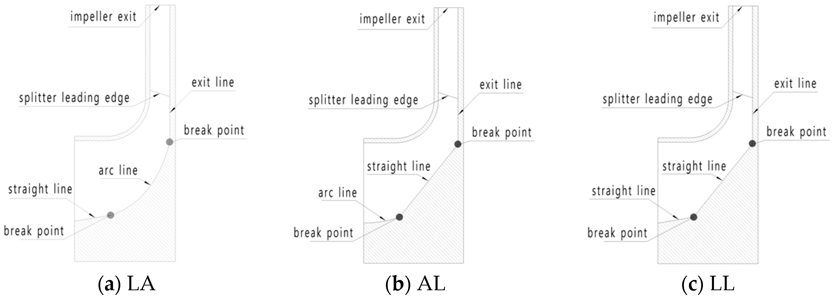
Figure 4.
Mesh of single flow passage.

Figure 5.
Mesh of full flow passage.

Figure 6.
2D cross-section.

Figure 7.
Performance curve.

Figure 8.
Aerodynamic parameters distribution on the meridional plane at the design point.

Figure 9.
Relative March number.

Figure 10.
Aerodynamic parameters distribution on meridional plane at the 0.85 flowrate.

Figure 11.
Relative Mach number distribution on blade to blade plane at design point.

Figure 12.
Relative Mach number distribution on blade to blade plane at 0.85 flowrate.

Figure 13.
Performance verses flow rate.

Figure 14.
Blade to blade performance comparison at design point, 50% span wise.

Figure 15.
Performance of whole flow passage at design point.

Figure 16.
Position of probe.

Figure 17.
Nodimensionalized pressure verses the time of six probes.

Figure 18.
Nodimensionalized pressure verses the step of probe 7.

Figure 19.
Dimensionless static pressure coefficient distribution at different time steps. DTS: dual-time step.
Figure 19.
Dimensionless static pressure coefficient distribution at different time steps. DTS: dual-time step.


Table 1.
Design parameters of prototype impeller.
| Parameters | Unit | Value |
|---|---|---|
| Inlet total pressure | kPa | 94.3 |
| Inlet total temperature | K | 371.15 |
| Mass flow rate | kg/s | 2.37 |
| Total-to-total pressure ratio | - | 1.4 |
| Number of impeller blades | - | 12/12 main/splitter blades |
| Impeller inlet tip diameter, D1 | m | 0.3464 |
| Impeller outlet diameter, D2 | m | 0.897 |
| Design rotational speed | rpm | 5600 |
| Exit blade angle (meridional) | deg | 0 |
Table 2.
Stall distinction.
| Impeller | Prototype | AL | LA | LL |
|---|---|---|---|---|
| SM | 0.17 | 0.27 | 0.15 | 0.29 |
SM: stall margin.
© 2018 by the authors. Licensee MDPI, Basel, Switzerland. This article is an open access article distributed under the terms and conditions of the Creative Commons Attribution (CC BY) license (http://creativecommons.org/licenses/by/4.0/).
Share and Cite
MDPI and ACS Style
Xie, H.; Song, M.; Liu, X.; Yang, B.; Gu, C. Research on the Simplified Design of a Centrifugal Compressor Impeller Based on Meridional Plane Modification. Appl. Sci. 2018, 8, 1339. https://doi.org/10.3390/app8081339
AMA Style
Xie H, Song M, Liu X, Yang B, Gu C. Research on the Simplified Design of a Centrifugal Compressor Impeller Based on Meridional Plane Modification. Applied Sciences. 2018; 8(8):1339. https://doi.org/10.3390/app8081339
Chicago/Turabian StyleXie, Hong, Moru Song, XiaoLan Liu, Bo Yang, and Chuangang Gu. 2018. "Research on the Simplified Design of a Centrifugal Compressor Impeller Based on Meridional Plane Modification" Applied Sciences 8, no. 8: 1339. https://doi.org/10.3390/app8081339
Note that from the first issue of 2016, this journal uses article numbers instead of page numbers. See further details here.