Article

Impact of the Temperature in the Evaluation of Battery Performances During Long-Term Cycling—Characterisation and Modelling

by
Odile Capron
1,2,*,
Joris Jaguemont
1,2,
Rahul Gopalakrishnan
1,2,
Peter Van den Bossche
1,2,
Noshin Omar
1,2 and
Joeri Van Mierlo
1,2
1
Mobility Logistics and Automotive Technology Research Centre (MOBI), Department of Electrical Engineering and Energy Technology (ETEC), Vrije Universiteit Brussel (VUB), 1050 Elsene, Belgium
2
Flanders Make, Celestijnenlaan 300-bus 4027, 3001 Heverlee, Belgium
*
Author to whom correspondence should be addressed.
Appl. Sci. 2018, 8(8), 1364; https://doi.org/10.3390/app8081364
Submission received: 23 July 2018 / Revised: 6 August 2018 / Accepted: 8 August 2018 / Published: 13 August 2018
(This article belongs to the Special Issue Green Energy and Applications)

Abstract

:

Featured Application

In the long term, results presented with this paper suggest to carry out in a systematic manner, the evaluation of batteries performances at the cycling temperature. According to this, in real applications as in automotive, it can be recommended to use the track of the temperature within the battery pack (e.g., mean) recorded by the battery management system, to define the temperature at which battery cells performances should be evaluated. In addition, room temperature can be used if needed for the comparison of battery cells performances, of same type that are though not operating at the same temperature.

Abstract

This paper presents the results regarding the thermal characterisation and modelling of high energy lithium-ion battery cells at both room (25 °C) and cycling (35 °C) temperatures. In this work two types of Nickel Manganese Cobalt (NMC) batteries are studied: a fresh (or uncycled) and an aged (or cycled) battery cells. The ageing of the studied NMC battery cells is achieved by means of accelerated ageing tests (i.e., repetition of numerous charge and discharge cycles) at 35 °C cycling temperature. Temperature at the surface of the battery cells is characterised, with a set of three discharge current rates 0.3C (i.e., 6 A), 1C (i.e., 20 A) and 2C (i.e., 40 A), and the evolutions at three different locations on the surface of the battery cells namely, at the top, in the center and at the bottom regions are measured. In addition, temperature and ageing dependent electrochemical-thermal modelling of the uncycled and cycled battery cells is also successfully accomplished in case of both room and cycling temperatures. Numerical simulations were carried out in case of high 2C constant current rate, and the assessment of the modelling accuracy by comparison of the predicted battery cells voltage and temperature with respect to the experimental data is further presented. With this paper, thermal performances of battery cells prior and after long-term cycling are evaluated at the cycling temperature, next to the ambient temperature. Hence, thermal characterisation and modelling results are more closely reflecting that encountered by the battery cells in real cycling conditions, so that their performances are believed in this way to be more objectively evaluated.

1. Introduction

Whether in mobile phones, in portable computers, for starting the car engine or for powering the satellite that sends radio communication signals down to earth [1,2,3], there is no wonder anymore that batteries have become essential components in our daily lives. Particularly, in the transportation sector as part of the daily mobility, electric vehicles (EVs) including hybrid electric vehicles (HEVs), plug-in hybrid electric vehicles (PHEVs) and pure battery electric vehicles (BEVs) are predicted to dominate the vehicle market [4,5]. In recent years, Lithium Nickel Manganese Cobalt (NMC) for use in positive electrodes eventually offered improved cycle life, thermal stability and energy density capabilities for lithium-ion batteries [6,7,8,9]. In practice, limitations in the lifetime of lithium-ion batteries still reveal often to be an issue in battery applications as in automotive [10,11,12,13].
Throughout their lifetime, batteries are experiencing several kinds of degradation mechanism. When cycled at high temperature, degradation mechanisms leading to capacity loss are observed through the rise of the positive electrode impedance especially at low lithium content. This may be due to the loss of conductive carbon or to a non-ionically conductive organic film at the surface of the electrode [14]. In addition, the electrodes expansion associated to the lithium insertion and extraction processes or the external stresses on the battery stack, are inducing mechanical mechanisms such as the viscoelastic creep behavior of the electrochemically inactive separator sheets. These mechanisms are altering the lithium-ion battery cells due to the pore closure effect, which is affecting the ion transport and is leading on the long term to internal resistance increase and capacity fade [15]. At the level of the porous electrodes (composed of solid active material particles and liquid electrolyte), diffusion-induced stresses are causing degradations in the active material particles, as demonstrated by non-local damage evolution modelling [16]. Life-prognostic methods for the predictions of damages on lithium-ion batteries caused by mechanical fatigue, can further be examined by physics-based modelling including the growth of solid electrolyte interface (SEI) at the carbonaceous negative electrode for instance, as single source of aging [17].
Further in case of advanced energy storage as Lithium metal (LMB) batteries, suitable for high energy density applications, robust SEI is required for improved cycling performances by preventing from the occurrence of dendrite growth. Factors such as the nature of the electrolyte, the temperature or the current density are influencing the SEI formation. Although, the introduction of pre-formed protective layer or modifications in electrode design or in electrolyte composition and additives represent efficient methods to modify the SEI layer [18]. Further in solid-state batteries, the expansion induced by the intercalation of Lithium ions in the electrodes active material particles is constrained by the solid-state electrolyte (SE), therefore leading to mechanical degradation. Mechanical degradation of the solid electrolyte (SE) is responsible for worsen transport properties, decreased capacity, and decrease in electrodes active material strength. Electro-chemo-mechanical finite element modelling are developed for this purpose for the study of the corresponding damage evolutions [19,20]. In view of this, long-term cycling of battery cells and their decreased performances are extensively studied in the literature [21,22,23,24,25].
For battery-powered vehicles, the operating temperature and the uniformity of the temperature distribution are two important factors at the scale of battery modules in which batteries are embedded [26]. For lithium-ion batteries the best operating temperatures are in the range between 25 °C and 40 °C [27]. Adiabatic tests in accelerated rate calorimeters demonstrate batteries thermal behaviour during charge and discharge, in abuse conditions such as in case of defective cooling systems in battery modules [28,29].
To avoid the occurrence of an excessive temperature rise [30] leading to the degradation in their lifetime or even worse to the thermal runaway phenomenon, local temperature of lithium-ion batteries should be carefully monitored.
So far although, research is commonly focusing on the evaluation of battery performances at room temperature rather than at the temperature at which they are cycled. However, battery performances evaluated in this manner obviously do not reflect those happening in real cycling conditions under which batteries are used and are further ageing. This is specifically believed to lead to biased and unfair assessments as regards batteries real capabilities. For accelerated ageing tests carried out at a temperature different from the room temperature, a lack of knowledge is hence recognized regarding the impact of the temperature chosen for the evaluation of batteries performances during long-term cycling. Therefore, with the research work achieved and presented in this paper, the impact of the temperature in the assessment of lithium-ion battery cells performances during long-term cycling is aimed to be investigated through characterisations together with numerical modelling for its further prediction.

2. Experimental

2.1. Studied Batteries

In this research work, high energy density (174 Wh/kg) lithium-ion battery cells (EIG C020, Chuncheongnam-do, South Korea) are studied. These batteries have been theoretically designed to be optimised for Electric (EV) and Plug-In Hybrid (PHEV) applications with a 20 Ah nominal capacity and Nickel Manganese Cobalt— L i N i 0.4 M n 0.4 C o 0.2 O 2 (NMC) positive electrodes. The battery cell specifications and characteristics are listed in Table 1.

2.2. Long-Term Cycling

For the ageing study presented in this research work, accelerated ageing tests have been performed by cycling of a high energy lithium-ion battery cell at 35 °C. The cycling conditions are defined by the following specifications:
  • The State-of-Charge (SoC) (in %) which is defined by the ratio between the battery cell actual capacity and its nominal capacity, as expressed in Equation (1):
    S o C = C actual / C nominal
  • The Depth-of-Discharge (DoD) (in %) which reflects the percentage of battery capacity that has been discharged expressed as a percentage of its actual maximum discharge capacity and is linked to the SoC in Equation (2):
    D o D = 100 % S o C
  • The middle State-of-Charge (mid-SoC) which is the SoC around which the battery cell is cycled.
  • Nominal Capacity which is the capacity expressed in Ampere-hours (Ah), specified by the manufacturer at specific conditions. In this research work, the nominal capacity of the studied battery cells is equal to 20 Ah.
  • The Charge/Discharge current rates expressed in terms of C-rate where the C-rate defines the rate at which a battery is discharged or charged relatively to its nominal capacity.
  • The Full Equivalent Cycles (FEC) (in case the cycling is performed with a DoD inferior to 100%), defines the amount of cycles needed to equal the same amount of Charge/Discharge capacity observed in case the cell would have been cycled with 100% DoD.
  • The Capacity Fade ( Δ C ) (in %) indicates the loss of capacity of the battery observed in time by comparison of its actual capacity with its measured initial capacity, as expressed in Equation (3):
    Δ C = 100 % × ( 1 C a c t u a l C i n i t i a l )
  • The State of Health (SoH) (in %) translates the ageing of the battery cell and is defined with the Equation (4):
    S o H = 100 % Δ C
In this research work, the cycling conditions were defined by 80% Depth of Discharge (DoD), which is defined as 50% mid-State of Charge (SoC) and 1C/1C (i.e., 20 A/20 A) current for the constant charge and discharge currents.
The reference amount of cycles is equal to 100 FEC where each cycle is defined by a repetition of one charge and one discharge sequences. The research work presented in this paper is based on one uncycled (or fresh) cell (i.e., cell 1) and one cycled (or aged) cell (i.e., cell 2) that was cycled up to 900 FEC. Table 2 summarizes the testing of the studied cells and their purpose. Cells 1 and 2 were aimed for thermal characterisations of fresh and aged battery cells, respectively.
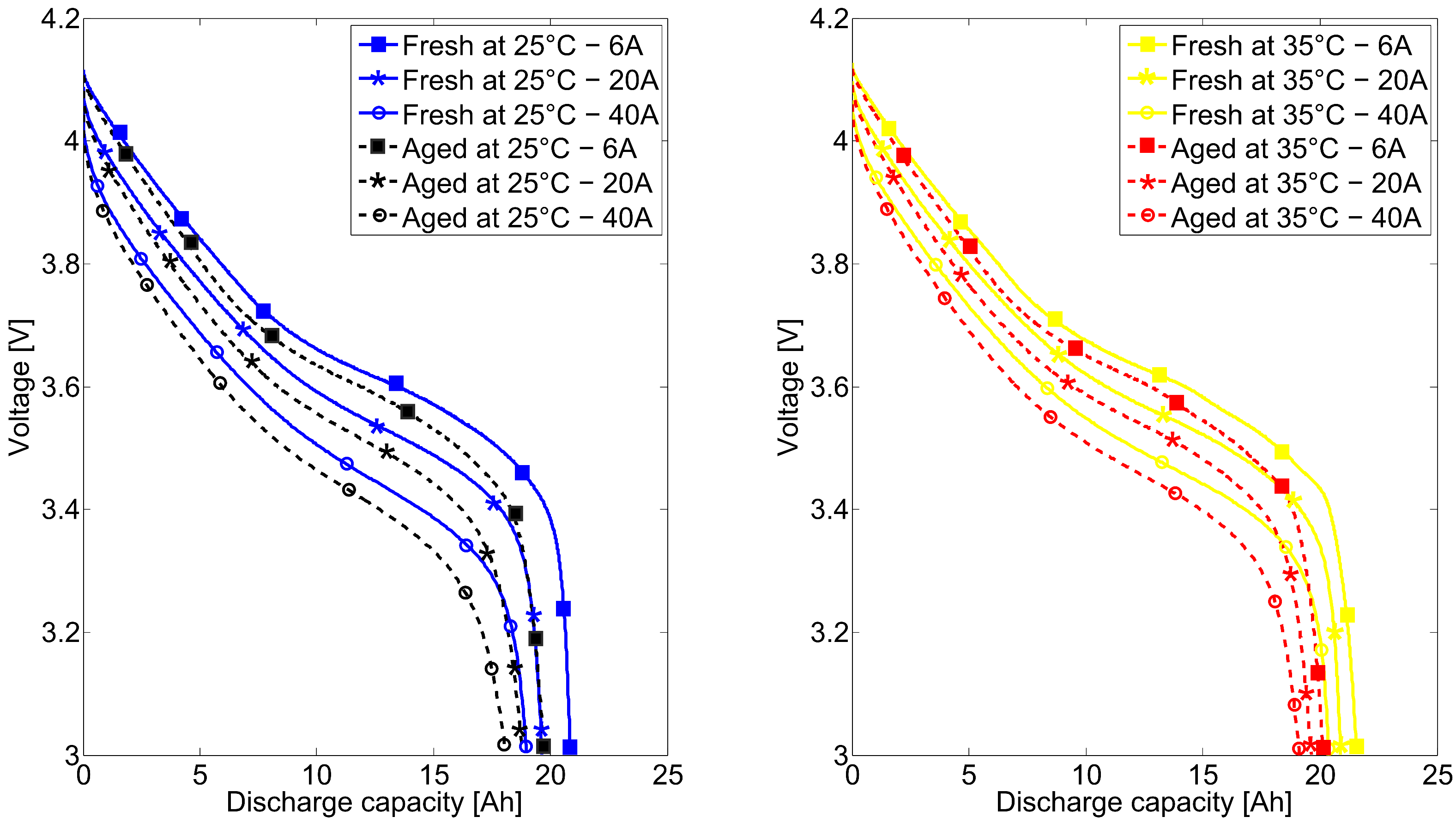
Capacity tests have been performed on both battery cells at the Begin Of Life (BoL) and as part of the Check-Ups (CUs) every 100 FEC on the cycled cell to monitor its SoH evolution and its capacity fade due to the accelerated ageing. This test is defined by a 3 times repetition of charge and discharge sequences at C/3 (6.666 A) current rate. In this paper, this test is presented at room temperature.
The evolution of the discharge capacity and the State-of-Health (SoH) of the cell 2 with the number of cycles is illustrated in Figure 1. The capacity loss observed in Figure 1 translates for the ageing of the cells caused by their cycling. The SoH evolution of the cells is based on the recording of their capacity at 25 °C every 100 FEC.
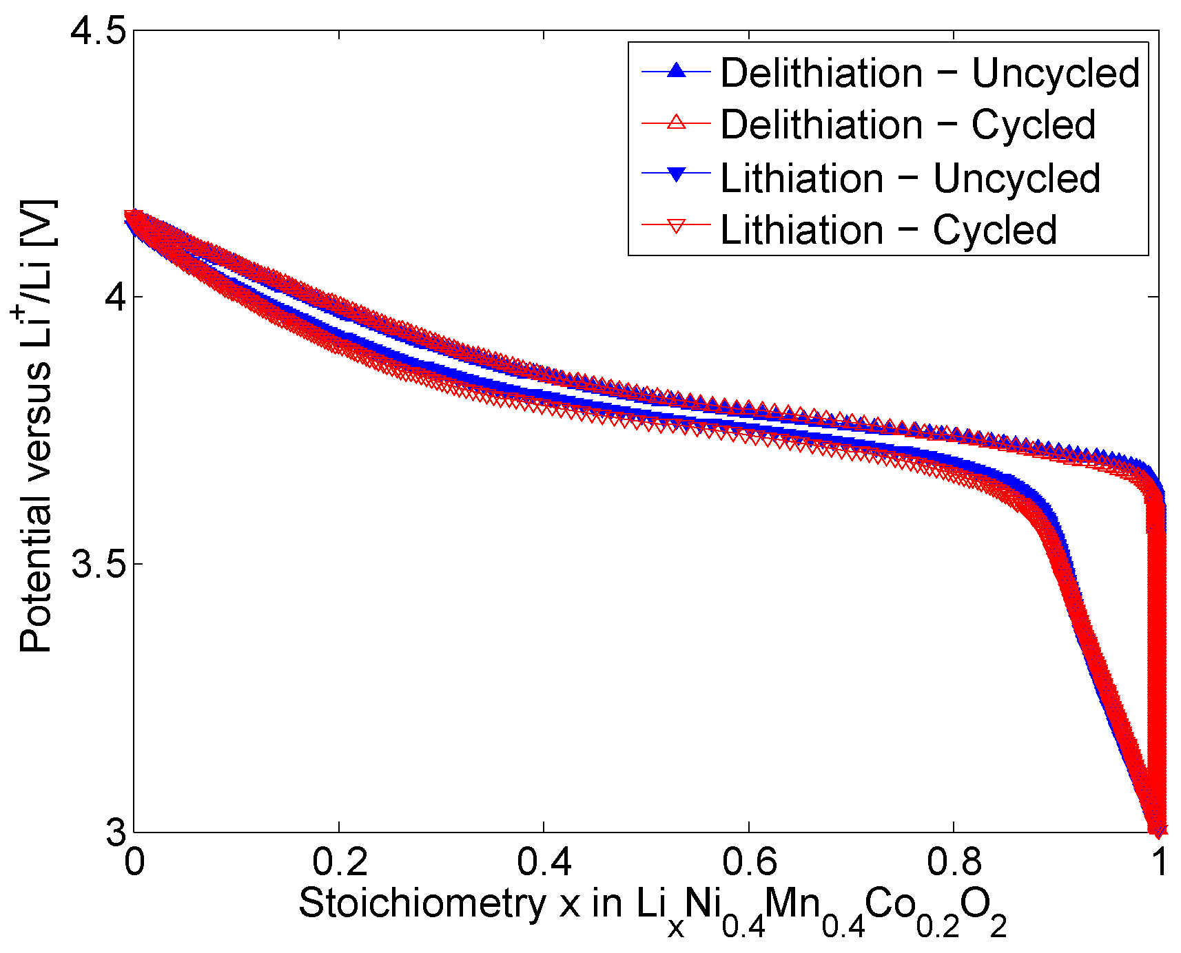
At the level of the electrodes, the measured Equilibrium Potential of the uncycled and cycled NMC positive electrodes are shown in in Figure 2. The Equilibrium Potential of the electrodes dependent on the stoichiometry are in agreement with [22,32,33]. Stoichiometry is defined by the amount of L i + intercalated in an electrode over the maximum amount of L i + that can be stored that electrode. As in Figure 2, the stoichiometry varies between 0 and 1 representing the x in L i x N i 0.4 M n 0.4 C o 0.2 . The highest Equilibrium Potential value corresponds to the lowest stoichiometry (0) of the electrode. With increasing stoichiometry, the Equilibrium Potential of the uncycled and cycled electrodes are decreasing down to 3 V during the lithiation of the electrodes. Reversely, as the delithiation of the electrodes proceeds the Equilibrium Potential of the electrodes are increasing up to 4.15 V. After long-term cycling, both loss of active material and loss of cyclable lithium are affecting the stoichiometries in the battery cells electrodes [34]. NMC electrodes exhibit lower potential near the maximum stoichiometry in the end of the lithiation process in accordance with [22,32,33]. This reflects for a faster lithiation process of cycled electrodes due to ageing. Reversely, higher potential near the minimum stoichiometry is observed for cycled electrodes due to their faster delithiation process. This behaviour leads to an increase in the hysteresis (difference between the Equilibrium Potential associated to the lithiation and the delithiation processes) of the cycled electrodes compared to uncycled electrodes.
In Figure 3 (left), the measured discharge capacity of the uncycled and cycled NMC electrodes are illustrated. The cycled electrode exhibit a discharge capacity equal to 5.67 mAh when the initially uncycled electrode show a capacity equal to 5.87 mAh. Conformingly to what expected, the cycled NMC electrode is discharging faster, leading to a lower discharge capacity than prior long-term cycling. The analysis of the incremental discharge capacity ( d Q / d V ) of both electrodes in Figure 3 (right) confirms the impact of the long-term cycling on the performances of the initially uncycled electrodes. Indeed, a decrease in the intensity of the peak in the d Q / d V curve is observed for the cycled electrode as observed in [22,32].
At the level of the negative electrodes, in Figure 4, the measured Equilibrium Potential of the uncycled and cycled Graphite electrodes are presented. As previously observed for the positive electrode and in agreement with the literature [33,35,36,37,38], the Equilibrium Potential of both uncycled and cycled electrodes are dependent on their stoichiometry. After long-term cycling, Graphite electrodes exhibit lower potential near the maximum stoichiometry in the end of the delithiation process. This reflects for a faster lithiation process of cycled electrodes due to ageing. Reversely, higher potential near the minimum stoichiometry is observed for cycled electrodes due to their faster delithiation process. These observations are in line with the behaviour of NMC electrodes measured after long-term cycling. Although, the hysteresis associated to the uncycled and cycled electrodes during their lithiation and delithiation processes is more marked for Graphite electrodes compared to NMC electrodes. This indicates for more significant ageing shown by the Graphite electrodes.
In Figure 5 (left), the measured discharge capacity of the uncycled and cycled Graphite electrodes are illustrated. The cycled electrode exhibit a discharge capacity equal to 7.07 mAh when the initially uncycled electrode show a capacity equal to 7.34 mAh. Similarly to what observed for the NMC electrodes, the cycled Graphite electrode is discharging faster, leading to a lower discharge capacity than prior long-term cycling. Although, the difference in the discharge capacity of the uncycled and cycled electrodes is more strong for Graphite electrodes compared to NMC electrodes. This also indicates for more significant ageing shown by the Graphite electrodes. The incremental discharge capacity ( d Q / d V ) curves of both electrodes, as shown in Figure 5 (right), are exhibiting three peaks (two majors and one minor) in accordance with the literature [35,36,37]. The analysis of the incremental discharge capacity ( d Q / d V ) of both electrodes in Figure 5 (right) confirms the impact of the long-term cycling on the performances of the initially uncycled electrodes. Indeed, the peaks in the d Q / d V curve of the cycled electrode exhibit lower intensity than observed for the uncycled electrode. In addition, the incremental capacity curve is seen to shift towards lower potentials. This might be explained by the faster lithiation process of the cycled compared to the uncycled electrodes as a consequence of the long-term cycling (in agreement with what suggested by Figure 4).

2.3. Thermal Characterisation

Thermal characterisation is performed at the scale of the whole fresh and aged pouch battery cells, by recording their temperature at three different locations namely at the top, middle (or center) and bottom regions as demonstrated in Figure 6.
Thermal behaviour of the battery cells basically results from the overall heat generation in the different layers inside the cells, as from the rate at which this heat can be transfered to the surroundings. It is assumed that the temperature distribution is independent of the z-direction, along the thickness of the battery cells. The thickness of the battery cells in the z-direction is fundamentally small compared to its two other dimensions (width and length) in x and y axes. Hence, the heat is propagating quickly by conduction along the thickness of the studied cells, so that the temperature distribution can be seen as uniform along the z-direction.

2.4. Numerical Simulation

In this work, numerical simulations are carried out according to an ageing and temperature dependent electrochemical-thermal modelling of the battery cells. The electrochemical simulations are performed with a pseudo two dimensional (P2D) modelling [39,40]. Wherein the electrodes are assumed to be porous materials composed of spherical particles immersed in the electrolyte. As part of physico-chemical models, electrochemical models are well documented in the literature [41,42,43]. These models are capable of accurately predicting the performance of lithium-ion batteries, which allows the battery manufacturers to optimise and improve the cell design and materials properties chosen for their products. With its wide set of physical parameters, porous electrochemical models are useful tools for design purposes of battery cells since they allow predicting and understanding the physical processes occurring inside the battery during its lifetime.
For the electrochemical modelling the internal structure of the battery is considered to be composed of multiple layers (electrodes, separator, current collectors) which is reduced (using a superposition approach) to a single unit layer made of negative current collector, negative electrode, separator, positive electrode and positive current collector.
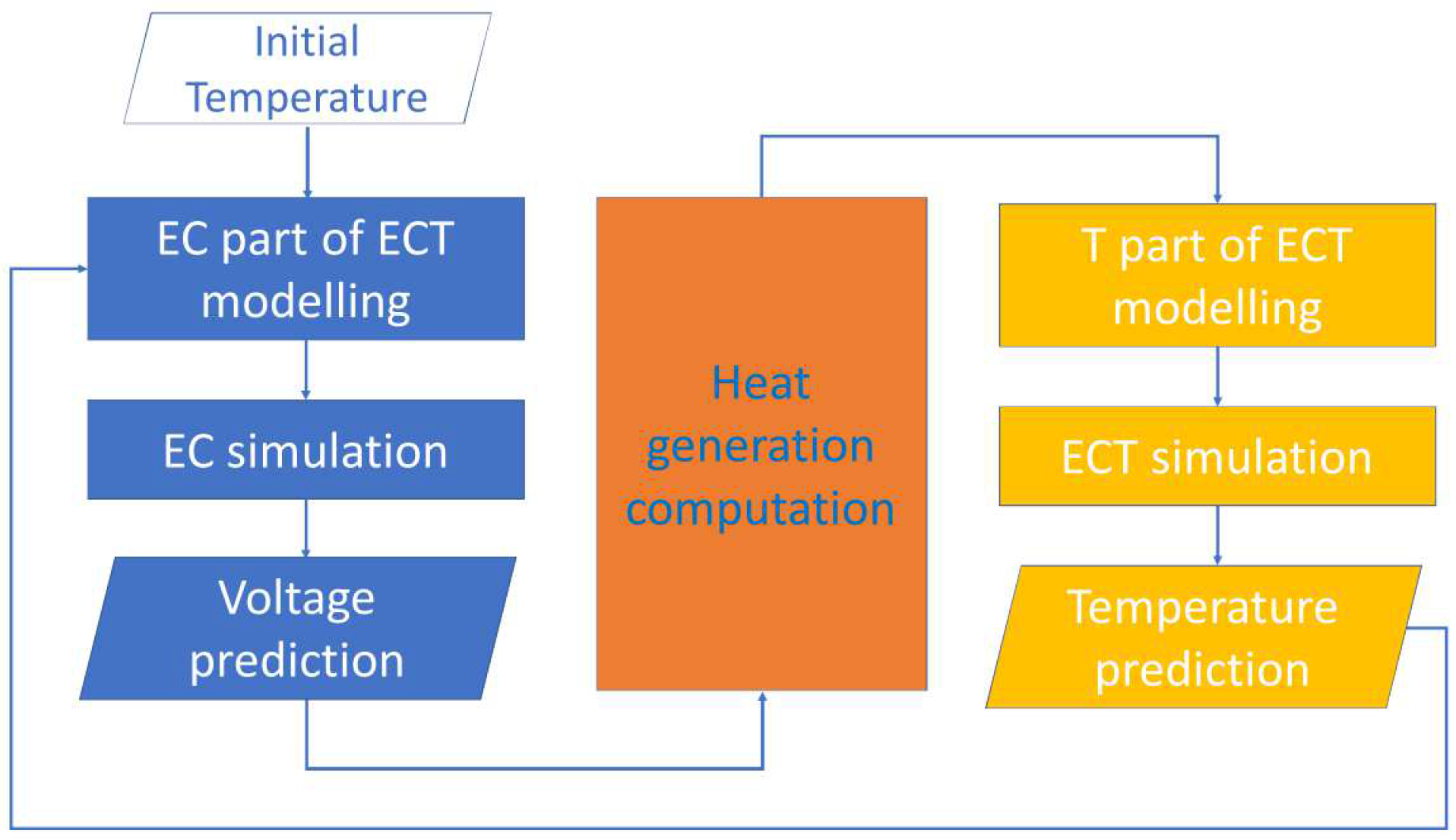
The coupling between the electrochemical (EC) and the thermal (T) parts of the developed temperature and ageing dependent electrochemical-thermal (ECT) modelling of the studied battery cells, is illustrated in Figure 7.
The heat equation which describes the heat transfer phenomenon occurring between the cell and its environment, for the coupling between both electrochemical and thermal modelling parts, is given in Equation (5):
ρ c p T t = ( k T ) + Q
where ρ represents the density, c p the heat capacity, T the temperature, k the thermal conductivity, and Q represents the heat generation.
The heat generation Q inside the cell is derived from Equation (6):
Q = j L i T ( U T ) reaction heat + j L i ( ϕ s ϕ e U ) active heat + [ σ s e f f ϕ s ϕ s + σ e e f f ϕ e ϕ e + κ D e f f l n ( c e ) ϕ e ] ohmic heat
where j L i is the transfer current due to the intercalation or deintercalation of lithium ions, ϕ s is the potential of the solid phase, ϕ e is the potential of the electrolyte phase, U is the open circuit voltage, T is the temperature, σ s e f f is the effective value of the electrical conductivity of the solid phase, σ e e f f is the effective value of the electrical conductivity of the electrolyte phase and c e represents the concentration of the electrolyte [44]. The first term in Equation (6) defines the reaction heat or the irreversible heat generation, the second term defines the reversible heat generation or active heat generation, while the third one (in brackets) defines the ohmic heat generation [45,46]. By definition, the reaction and the reversible heat generations are caused by the negative and the positive electrodes, while the ohmic heat generation comes from the electrolyte and both negative and positive electrodes.
The resulting thermo-physical properties of the whole battery cell after computation, according to Equations (A1, A2, A3 and A4) and Table A4, are summarised in Table 3.
Table A1 and Table A2 list the electrochemical parameters values associated to the uncycled and cycled porous electrodes, respectively, while Table A3 lists the electrochemical parameters values associated to the electrolyte and the separator of the studied battery cells.
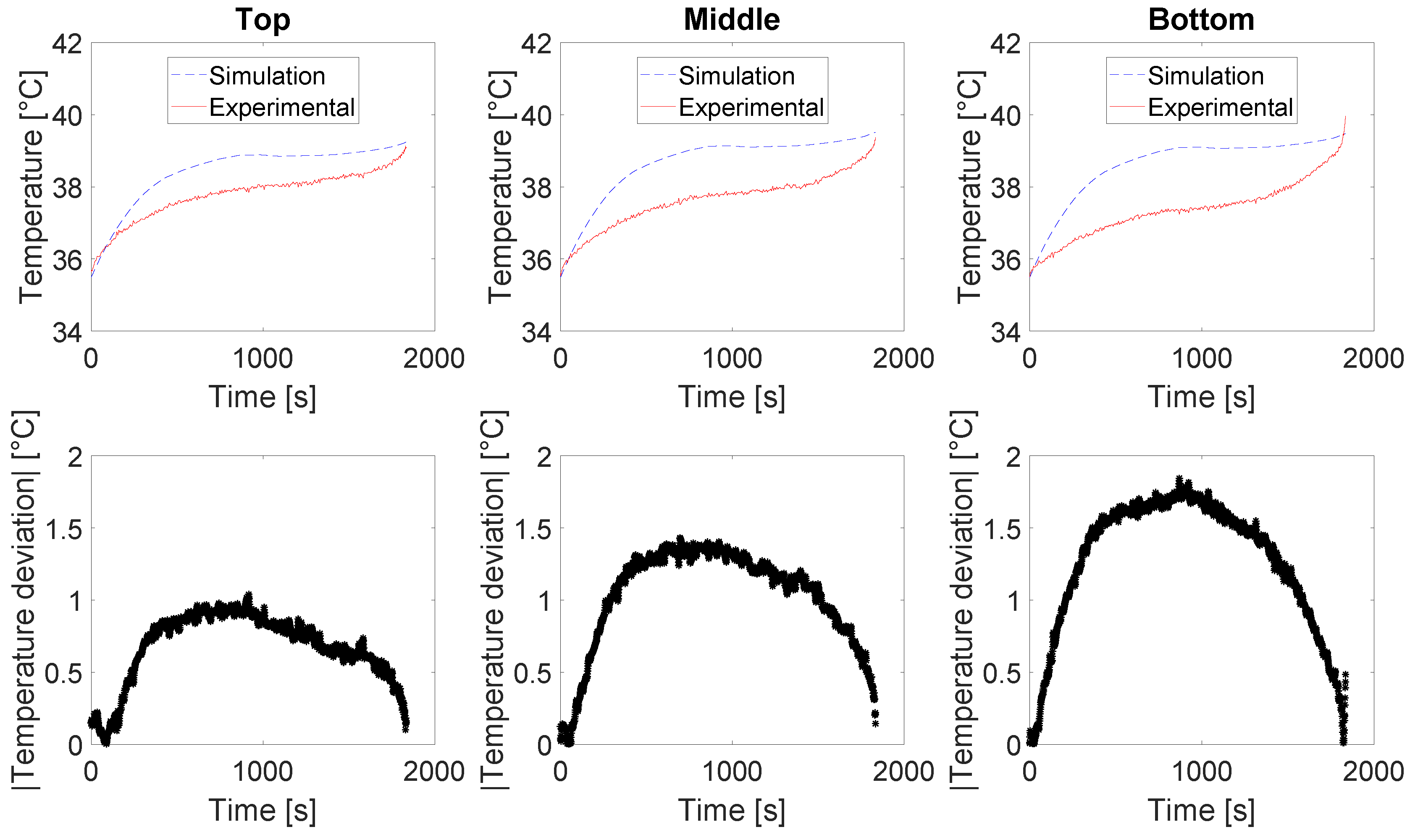
Figure 8 illustrates the different steps carried out in this research work as part of the electrochemical-thermal modelling of the fresh and aged battery cells at both room and cycling temperature. First, the domains and the geometry related to the battery cells are defined, and further associated to their respective materials properties. After discretisation by meshing of the domains, the physics and the boundary conditions associated to each domain are defined for the numerical solving of the governing equations. Last, as output of the numerical simulations, the predicted voltage and temperature of the battery cells are compared against experimental data for validation of the electrochemical-thermal modelling.
The commercial finite element software COMSOL Multiphysics® 4.3b was used for solving of the governing electrochemical and thermal differential equations. The temperature and ageing dependent modelling of the studied battery cells was achieved via the COMSOL® (Stockholm, Sweden) LiveLinkTM for MATLAB® interface. A fully coupled MUMPS direct solver was opted as linear solver with a minimum step tolerance equal to 1 × 10 4 . The mesh resolution for the discretisation of the 3D battery cells and the 1D equivalent electrochemical layer domains, consist of a total of 2163 tetrahedral elements of minimum size equal to 1.72 × 10 2 and 158 elements of 1.57 × 10 6 minimum size, respectively.

3. Results and Discussion

3.1. Experimental Characterisation—Fresh Cell

3.1.1. Voltage Response—Room and Cycling Temperatures

The voltage response of the fresh battery cell (or cell 1) measured during the discharge processes under various current rates 6 A, 20 A, 40 A (corresponding to 0.3C, 1C, 2C) at 25 °C and 35 °C are presented in Figure 9. The voltage responses in Figure 9 highlight an increase in capacity of the fresh cell while discharged at the cycling temperature. The energy barrier required for the electrochemical reaction linked to the insertion and extraction processes of L i + in the electrodes is reduced as the temperature increases. As a result, a greater amount of L i + can be displaced, resulting in greater discharge capacities exhibited by the battery cells.

3.1.2. Thermal Response—Room and Cycling Temperatures

The thermal response in terms of temperature increase of the cell 1 measured during the discharge process under various current rates 6 A, 20 A, 40 A (corresponding to 0.3C, 1C, 2C) at 25 °C and 35 °C at the top, middle and bottom regions are presented in Figure 10. The measurements were performed in a climate chamber (Clima Temperatur Systeme GmbH (CTS), Hechingen, Germany) in which the cell is subjected to forced convection. The highest temperature rises are established in the middle and bottom regions of the cell, with up to 25% increase. Although for low current rates similar evolutions are observed for both studied temperatures in the three regions, at high current rates more significant temperature rises are observed at room in comparison to the the cycling temperature. The differences in the temperature increases at the three top, middle and bottom regions indicate a non-uniform temperature distribution on the surface of the fresh cell. The temperature distribution originates from the non-uniform potential developed in the electrodes sheets leading to non-uniform current density. The heat generation being proportional to the square root of the current, is hence non-uniform and leads in turn to non-uniform temperature distribution at the surface of the battery cell. Further, differences in the temperature increase of an uncycled battery cell under room compared to the cycling temperature in Figure 10 are around 10%.

3.2. Experimental Characterisation—Aged Cell

3.2.1. Voltage Response—Room and Cycling Temperatures

The voltage response of the aged battery cell (or cell 2) measured during the discharge process under various current rates 6 A, 20 A, 40 A (corresponding to 0.3C, 1C, 2C) at 25 °C and 35 °C are presented in Figure 11. Similarly to what observed for the fresh cell, the voltage responses of the aged cell in Figure 11 highlight an increase in capacity while discharged at the cycling temperature. The energy barrier required for the electrochemical reaction to occur is reduced as the temperature increase. With a lower energy barrier associated to the insertion and extraction processes of L i + in the electrodes, a greater amount of L i + can be displaced, resulting in greater discharge capacities of the battery cells.

3.2.2. Thermal Response—Room and Cycling Temperatures

The thermal response in terms of temperature increase of the cell 2 measured during the discharge process under various current rates 6 A, 20 A, 40 A (corresponding to 0.3C, 1C, 2C) at 25 °C and 35 °C at the top, middle and bottom regions are presented in Figure 12. The measurements were performed in a climate chamber (Clima Temperatur Systeme GmbH (CTS), Hechingen, Germany) in which the cell is subjected to forced convection. Similarly to the fresh cell, the difference observed in the temperature increases at the three top, middle and bottom regions on the surface of the aged battery cell indicate for a non-uniform temperature distribution. The highest temperature rises are detected in the middle and bottom regions of the cell, with up to more than 30% increase under room temperature. The evolution of the temperature in the three regions is similar at low current rates, although more significant temperature rises are observed at high current rates under room in comparison to the the cycling temperature. These differences in temperature increases initially observed in Figure 10, are seen now in Figure 12 to be even more prominent due to the ageing of the battery cell caused by long-term cycling.
These results stress the importance of a good thermal monitoring of cycled battery cells, especially in real applications when embedded in battery modules and packs. Thermal runaway phenomenon at the scale of a battery pack is in practice often initiated by the thermal failure of a single cell, which in turns causes other cells to fail. Within a pack composed of aged cells, this phenomenon is even more likely to occur and hence critical. The strong difference up to 15% (Figure 12) in the temperature increase of a cycled battery cell under room compared to the cycling temperature, emphasises for the issues of possible mismatch in the thermal behaviour of battery cells at the level of a battery pack not being initially appropriately conditioned.

3.3. Cells Voltage and Thermal Responses Comparisons

The comparison between the voltage response of the fresh and aged cells at 25 °C and 35 °C are illustrated in Figure 13, respectively. A decrease in capacity of the aged cell while discharged is observed at both room and cycling temperature. Considering the long-term cycling under 35 °C, the capacity fade observed can be attributed to the side reactions inducing further an important loss of usable L i + and active material particles participating in the electrochemical lithiation/delithiation reactions inside the cell.
The comparison between the temperature increases of the fresh and aged cells at 25 °C and 35 °C are illustrated in Figure 14 and Figure 15, respectively. These figures highlight the impact of the choice of the temperature for assessing the thermal responses of fresh and aged cells respectively, when discharged with various currents. At both room and cycling temperatures, the aged cell exhibits more pronounced temperature rises compared to the fresh cell. After long-term cycling, the voltage of the aged cell tends to be lowered and the internal resistance tends to increase, which leads to greater heat generation and hence greater temperature rises. Further, Figure 14 and Figure 15 reveal that when assessed at the same temperature (respectively at room or cycling), the evolutions of the temperature at the surface of the battery cell prior in contrast to after long-term cycling are although not significantly differing. These differences are less in comparison to the differences observed in the thermal behaviour of the cells when assessed at different temperatures (either room/cycling or cycling/room). At both room and cycling temperatures, the maximum difference between the fresh and aged cells surface temperature evolutions being round 5%.
In the long term, results presented in Section 3.1 and Section 3.2 suggest to carry out in a systematic manner, the evaluation of batteries performances at the cycling temperature. According to this, in real applications as in automotive, it can be recommended to use the track of the temperature within the battery pack (e.g., mean) recorded by the battery management system, to define the temperature at which battery cells performances should be evaluated. In addition, room temperature can be used if needed for the comparison of battery cells performances, of same type that are though not operating at the same temperature.

3.4. Numerical Modelling

3.4.1. Voltage Predictions

As outcome of the numerical simulations, the predicted voltage response of the cell 1 (or uncycled cell) at room and cycling temperatures are illustrated in Figure 16 and Figure 17 during high constant current discharge (2C i.e., 40 A). From the comparison with the experimental measurements, the absolute value of the voltage deviations are overall less than 2%. Particularly, at the beginning and at the end of the discharge curves, highest voltage deviations can be found due to steeper slopes presented in the voltage behaviour of the battery cell. The good agreement in the simulated and the experimental voltages observed in Figure 16 and Figure 17 translates for the accurate electrochemical characterisation as for the effective implementation of the parameters estimation in the framework of the coupled electrochemical-thermal modelling at both room and cycling temperatures.
The predicted voltage response of cell 2 (or cycled cell) at room and cycling temperatures are illustrated in Figure 18 and Figure 19 during high constant current discharge (2C i.e., 40 A). From the comparison with the experimental measurements, the absolute value of the voltage deviations are overall less than 2% and 3%, respectively. Particularly, at the beginning and at the end of the discharge curve, highest voltage deviations can be found due to steeper slopes presented in the voltage behaviour of the battery cell. The good agreement in the simulated and the experimental voltages observed in Figure 18 and Figure 19 translates for the accurate electrochemical characterisation as for the effective implementation of the parameters estimation in the framework of the coupled electrochemical-thermal modelling at both room and cycling temperatures.
The slightly longer simulation time observed for the voltage curves in Figure 18, highlight the effect of the temperature on the internal battery cell electrochemical processes and further the non-negligible role of the temperature in the assessment of the battery performances during long-term cycling.

3.4.2. Temperature Predictions

As outcome of the numerical simulations, the predicted temperature behaviour of cell 1 (or uncycled cell) at room and cycling temperatures are illustrated in Figure 20 and Figure 21 during high constant current discharge (2C i.e., 40 A). From the comparison with the experimental measurements at three different locations (Top, Middle and Bottom regions), the absolute value of the temperature deviations are overall less than 1 and 2 °C, respectively. The good agreement in the simulated and the experimental data observed in Figure 20 and Figure 21 translates for the accurate electrochemical-thermal characterisation and for the effective temperature predictions delivered by the coupled electrochemical-thermal modelling of the studied battery cells at room temperature. The temperature differences in the three regions indicate for non-uniform temperature distribution taking place at the surface of the battery cell. Further, these results emphasise the need for appropriate thermal management solutions that would on the long term decrease the battery ageing, by preventing the development of temperature differences at the surface of the battery cell (i.e., hot and cold regions).
The predicted temperature behaviour of a cycled cell at room and cycling temperatures are illustrated in Figure 22 and Figure 23 during high constant current discharge (2C i.e., 40 A). Predictions of the temperature distribution under 35 are illustrated in Figure 24. With these results, the higher temperature observed at the surface of the cycled battery cell, may be attributed to the rise in internal resistance, and hence in the heat generation inside the cell due to the ageing of the cell caused by long-term cycling. From the comparison with the experimental measurements at three different locations (Top, Middle and Bottom regions), the absolute value of the temperature deviations are overall less than 1.5 and 2 °C, respectively. In view of the results regarding cell 2 (or cycled battery) cell, less temperature uniformity is observed in Figure 23 compared to the case of an uncycled cell in Figure 21. The latter observation suggest for differences in the internal resistance of the cell in the different regions. Further thermal investigations might confirm this behaviour. The good agreement in the simulated and the experimental data observed in Figure 22 and Figure 23 translates for the accurate electrochemical-thermal characterisation and for the effective temperature predictions delivered by the coupled electrochemical-thermal modelling of the studied battery cells at room temperature.

4. Conclusions

With this paper, thermal characterisation of both uncycled and cycled battery cells, is originally performed and investigated at the cycling temperature (or 35 °C), beyond the commonly studied 25 °C room temperature. By considering the cycling temperature, thermal characterisations of the battery cells are seen to more closely reflect that encountered in real cycling conditions, leading to a more objective assessment of the battery cells performances.
Experimental investigations of the temperature at the surface of the uncycled and cycled battery cells at various current rates revealed the impact of ageing, with higher temperature increases observed at the cycled battery cell surface. Temperature evolution at three different locations on the surface of the fresh battery cell namely, top, center and bottom regions also indicate for non-uniformity of the temperature distribution, which phenomenon is further accentuated for cycled battery cells that experienced long-term cycling.
Additionally, temperature and ageing dependent electrochemical-thermal modelling of the uncycled and cycled battery cells at both room and cycling temperatures were successfully achieved for high constant discharge current rates (2C i.e., 40 A), with absolute deviations less than 3% (voltage predictions) and 2 °C (temperature predictions).
In the long term, results presented with this paper suggest to carry out in a systematic manner, the evaluation of batteries performances at the cycling temperature. According to this, in real applications as in automotive, it can be recommended to use the track of the temperature within the battery pack (e.g., mean) recorded by the battery management system, to define the temperature at which battery cells performances should be evaluated. In addition, room temperature can be used if needed for the comparison of battery cells performances, of same type that are though not operating at the same temperature.

Author Contributions

O.C. and J.J. designed and performed the experiments, and further conducted the analysis of the data for the writing of the paper. R.G. and P.V.D.B. made suggestions that contributed to improve the manuscript. J.V.M. and N.O. contributed to the supervision of the research. All authors have read and approved the final manuscript.

Funding

This research was partially funded by the European Union through the NMP.2013-1 Batteries2020 project: Grant agreement GC.NMP.2013-1/GA NO608936.

Acknowledgments

We acknowledge Flanders Make for the support to our team. This research work was partially supported by the European Union through the NMP.2013-1 Batteries2020 project: Grant agreement GC.NMP.2013-1/GA NO608936.

Conflicts of Interest

The authors declare no conflict of interest.

Appendix A

Table A1 lists the electrochemical parameters values associated to the uncycled porous electrodes.
Table A1. Electrochemical parameters values: uncycled porous electrodes.
ParametersGraphiteNMC
Electrode thickness79 × 10 6 m ( a ) 70 × 10 6 m ( a )
Volume fraction of AM0.52 ( c ) 0.45 ( c )
Volume fraction of electrolyte (i.e., porosity)0.31 ( c ) 0.37 ( c )
Current collector thickness14 × 10 6 m ( a ) 21 × 10 6 m ( a )
Solid phase electrode potentialFigure 4 [V] ( a ) Figure 2 [V] ( a )
Maximum lithium ions concentration34,984 mol/m 3 ( a ) 48,900 mol/m 3 ( a ) , [47]
AM particle (equivalent) radius5.40 × 10 6 m ( a ) 3.44 × 10 6 m ( a )
L i + diffusion coefficient in the solid phase[47] [V] ( a ) [47] [V] ( a )
L i + diffusion coefficient activation Energy18.7 × 10 3 J/mol ( a ) 27.6 × 10 3 J/mol ( a )
Reaction rate constant9 × 10 13 m/s ( c ) 8.5 × 10 12 m/s ( c )
Electrode electronic conductivity100 S/m ( b ) , [48]0.6 S/m ( c )
Current collector electronic conductivity5.998 × 10 7 S/m ( b ) , [48]3.774 × 10 7 S/m ( b ) , [49]
With the subscripts ( a ) , ( b ) , ( c ) in Table A1 denoting for the origin of the parameters as follows: (a) experimentally determined; (b) literature and (c) estimated.
Table A2 lists the electrochemical parameters values associated to the cycled porous electrodes.
Table A2. Electrochemical parameters values: cycled porous electrodes.
ParametersGraphiteNMC
Electrode thickness79 × 10 6 m ( a ) 70 × 10 6 m ( a )
Volume fraction of AM0.52 ( c ) 0.45 ( c )
Volume fraction of electrolyte (i.e., porosity)0.30 ( c ) 0.37 ( c )
Current collector thickness14 × 10 6 m ( a ) 21 × 10 6 m ( a )
Solid phase electrode potentialFigure 4 [V] ( a ) Figure 2 [V] ( a )
Maximum lithium ions concentration34,795 mol/m 3 ( a ) 49,700 mol/m 3 ( a ) , [47]
AM particle (equivalent) radius5.44 × 10 6 m ( a ) 3.06 × 10 6 m ( a )
L i + diffusion coefficient in the solid phase[47] [V] ( a ) [47] [V] ( a )
L i + diffusion coefficient activation Energy80.6 × 10 3 J/mol ( a ) 46 × 10 3 J/mol ( a )
Reaction rate constant5 × 10 13 m/s ( c ) 6 × 10 12 m/s ( c )
Electronic conductivity100 S/m ( b ) , [48]0.599 S/m ( c )
Current collector electronic conductivity5.998 × 10 7 S/m ( b ) , [48]3.774 × 10 7 S/m ( b ) , [49]
With the subscripts ( a ) , ( b ) , ( c ) in Table A2 denoting for the origin of the parameters as follows: (a) experimentally determined; (b) literature and (c) estimated.
In Table A1 and Table A2, for the experimental determination of the parameters associated to the superscript (a), both NMC and Graphite electrodes sheets were recovered from the uncycled and cycled battery cells according to the procedure detailed in [47].
The electrodes thickness and the current collectors thickness were measured by means of a thickness gauge (i.e., elcometer).
Solid phase electrode potential of both Graphite and NMC electrodes were measured by charging first 18 mm diameter electrodes punches (in EL cells containers (Hamburg, Germany)) to their upper cut-off potential using a CC-CV method (C/30–0.5 C) (as referred in [47]) and discharging them subsequently to their lower cut-off voltage with C/30 (ca. 250 μ A).
Maximum lithium ions concentration in both electrodes were determined from XRD (X-ray Diffraction) experiments as referred by the procedure in [47].
Radius of active material (AM) particles in both electrodes were determined from the analysis of SEM (Scanning Electron Microscopy) micrographs as referred in [47].
L i + diffusion coefficient in the solid phase in both electrodes were determined from GITT (Galvanostatic Intermittent Titration Technique) according to the procedure detailed in [47].
The activation Energy associated to the L i + diffusion coefficient in the electrodes was determined during the discharge of the electrodes at each 10% discharge step, by means of an incremental temperature profile between 20 °C and 30 °C including 5 steps, each of 2.5 °C increment.
The volume fraction of active material (AM) and electrolyte in both electrodes, the electrochemical reaction rate constant associated to both electrodes, as well as the electronic conductivity of the NMC electrode were estimated. The estimation of these parameters was performed using a non linear least square based algorithm, which was implemented via MATLAB® as referred in [50].
The remaining parameters were referred directly to the literature as indicated by the corresponding reference(s) next to the superscript (b).
Table A3 lists the electrochemical parameters values associated to the electrolyte and the separator of the studied battery cells.
Table A3. Electrochemical parameters values: electrolyte and separator.
ParametersValue
Thickness separator24 × 10 6 m ( a )
Porosity separator0.42 ( b ) , [51]
L i + diffusion coefficient in the electrolyte1.5 × 10 10 m 2 /s ( b ) , [51]
L i + initial concentration in the electrolyte2000 mol/m 3 ( c )
Transference number of electrolyte for L i + diffusion0.38 ( b ) , [52]
With the subscripts ( a ) , ( b ) , ( c ) in Table A3 denoting for the origin of the parameters as follows: (a) experimentally determined; (b) literature and (c) estimated. The separator thickness was measured by means of a thickness gauge (i.e., elcometer). The L i + initial concentration in the electrolyte was estimated using a non linear least square based algorithm which was implemented via MATLAB® as referred in [50].
The thermo-physical properties of the electrodes of the studied battery cells are listed in Table A4.
Table A4. Thermo-physical properties of the electrodes, separators, current collectors of the NMC/Graphite type of battery cell.
Thermal ParameterValueUnit
Negative electrode
      ρ 1555[kg/m 3 ]
      C p 1437[J/kg·K]
      k T 1.04 [W/m·K]
Positive electrode
      ρ 2895[kg/m 3 ]
      C p 1270[J/kg·K]
      k T 1.58 [W/m·K]
Separator electrode
      ρ 1017[kg/m 3 ]
      C p 1978[J/kg·K]
      k T 0.34 [W/m·K]
Negative current collector
      ρ 8933[kg/m 3 ]
      C p 385[J/kg·K]
      k T 398[W/m·K]
Positive current collector
      ρ 2702[kg/m 3 ]
      C p 903[J/kg·K]
      k T 238[W/m·K]
The reported thermo-physical electrodes properties are obtained for similar electrodes in the literature [49]. The thermo-physical properties of the whole batteries are computed from those of their constitutive elements (electrodes, current collectors and separator).
The thermal capacity of each studied battery cell is defined as follows:
C p = i δ i · C p i i δ i
The internal density of each studied battery cell is defined as follows:
ρ = i δ i · ρ i i δ i
with δ i the thickness of each of the battery constitutive elements, C p i and ρ i the heat capacity and the density of each constitutive element, respectively.
Through-plane and in-plane conductivities of the battery cells are defined with Equations A3 and A4, respectively.
k z = i δ i i δ i k i
k x y = i δ i · k i i δ i
with δ i and k i the thickness and the thermal conductivity of each battery constitutive element, respectively.

References

  1. Goodenough, J.; Kim, Y. Challenges for rechargeable batteries. J. Power Sources 2011, 196, 6688–6694. [Google Scholar] [CrossRef]
  2. Armand, M.; Tarascon, J. Building better batteries. Nature 2008, 451, 652–657. [Google Scholar] [CrossRef] [PubMed]
  3. Raijmakers, L.; Danilov, D.; Van Lammeren, J.; Lammers, M.; Notten, P. Sensorless battery temperature measurements based on electrochemical impedance spectroscopy. J. Power Sources 2014, 247, 539–544. [Google Scholar] [CrossRef]
  4. Thomas, C. Transportation options in a carbon-constrained world: Hybrids, plug-in hybrids, biofuels, fuel cell electric vehicles, and battery electric vehicles. Int. J. Hydrogen Energy 2009, 34, 9279–9296. [Google Scholar] [CrossRef]
  5. Berckmans, G.; Messagie, M.; Smekens, J.; Omar, N.; Vanhaverbeke, L.; Van Mierlo, J. Cost Projection of State of the Art Lithium-Ion Batteries for Electric Vehicles Up to 2030. Energies 2017, 10, 1314. [Google Scholar] [CrossRef]
  6. Li, Z.; Chernova, N.A.; Roppolo, M.; Upreti, S.; Petersburg, C.; Alamgir, F.M.; Whittingham, M.S. Comparative Study of the Capacity and Rate Capability of LiNiy Mny Co1−2y O2 (y = 0.5, 0.45, 0.4, 0.33). J. Electrochem. Soc. 2011, 158, A516–A522. [Google Scholar] [CrossRef]
  7. Fu, C.; Li, G.; Luo, D.; Li, Q.; Fan, J.; Li, L. Nickel-Rich Layered Microspheres Cathodes: Lithium/Nickel Disordering and Electrochemical Performance. ACS Appl. Mater. Interfaces 2014, 6, 15822–15831. [Google Scholar] [CrossRef] [PubMed]
  8. Gopalakrishnan, R.; Goutam, S.; Miguel Oliveira, L.; Timmermans, J.M.; Omar, N.; Messagie, M.; Van den Bossche, P.; Van Mierlo, J. A Comprehensive Study on Rechargeable Energy Storage Technologies. ASME J. Electrochem. Energy Convers. Stor. 2017, 13, 040801. [Google Scholar] [CrossRef]
  9. Yoo, K.S.; Kang, Y.H.; Im, K.R.; Kim, C.S. Surface Modification of Li(Ni0.6Co0.2Mn0.2)O2 Cathode Materials by Nano-Al2O3 to Improve Electrochemical Performance in Lithium-Ion Batteries. Materials 2017, 10, 1273. [Google Scholar] [CrossRef] [PubMed]
  10. Burns, J.; Kassam, A.; Sinha, N.N.; Downie, L.E.; Solnickova, L.; Way, B.M.; Dahn, J.R. Predicting and Extending the Lifetime of Li-Ion Batteries. J. Electrochem. Soc. 2013, 160, A1451–A1456. [Google Scholar] [CrossRef]
  11. Smith, K.; Earleywine, M.; Wood, E.; Neubauer, J.; Pesaran, A. A comparison of Plug-In Hybrid Electric Vehicle Battery Life across Geographies and Drive Cycles. In Proceedings of the 2012 SAE World Congress and Exhibition, Detroit, MI, USA, 24–26 April 2012. [Google Scholar]
  12. De Hoog, J.; Timmermans, J.M.; Ioan-Stroe, D.; Swierczynski, M.; Jaguemont, J.; Goutam, S.; Omar, N.; Van Mierlo, J.; Van Den Bossche, P. Combined cycling and calendar capacity fade modeling of a Nickel-Manganese-Cobalt Oxide Cell with real-life profile validation. Appl. Energy 2017, 200, 47–61. [Google Scholar] [CrossRef]
  13. Rahn, C.; Wang, C. Battery Systems Engineering; John Wiley and Sons Ltd.: Chichester, UK, 2013. [Google Scholar]
  14. Shim, J.; Kostecki, R.; Richardson, T.; Song, X.; Striebel, K. Electrochemical analysis for cycle performance and capacity fading of a lithium-ion battery cycled at elevated temperature. J. Power Sources 2002, 112, 222–230. [Google Scholar] [CrossRef] [Green Version]
  15. Peabody, C.; Arnold, C.B. The role of mechanically induced separator creep in lithium-ion battery capacity fade. J. Power Sources 2011, 196, 8147–8153. [Google Scholar] [CrossRef]
  16. Behrou, R.; Maute, K. Multiscale Modeling of Non-Local Damage Evolution in Lithium-Ion Batteries. ECS Trans. 2017, 77, 1163–1177. [Google Scholar] [CrossRef]
  17. Safari, M.; Morcrette, M.; Teyssot, A.; Delacourt, C. Life-Prediction Methods for Lithium-Ion Batteries Derived from a Fatigue Approach I. Introduction: Capacity-Loss Prediction Based on Damage Accumulation. J. Electrochem. Soc. 2010, 157, A713–A720. [Google Scholar] [CrossRef]
  18. Cheng, X.B.; Zhang, R.; Zhao, C.Z.; Wei, F.; Zhang, J.G.; Zhang, Q. A Review of Solid Electrolyte Interphases on Lithium Metal Anode. Adv. Sci. 2016, 3, 1500213. [Google Scholar] [CrossRef] [PubMed]
  19. Bucci, G.; Swamy, T.; Chiang, Y.M.; Carter, W.C. Modeling of internal mechanical failure of all-solid-state batteries during electrochemical cycling, and implications for battery design. J. Mater. Chem. A 2017, 5, 19422–19430. [Google Scholar] [CrossRef] [Green Version]
  20. Behrou, R.; Maute, K. Numerical Modeling of Damage Evolution Phenomenon in Solid-State Lithium-Ion Batteries. J. Electrochem. Soc. 2017, 164, A2573–A2589. [Google Scholar] [CrossRef]
  21. Crawford, A.J.; Huang, Q.; Kintner-Meyer, M.C.; Zhang, J.G.; Reed, D.M.; Sprenkle, V.L.; Viswanathan, V.V.; Choi, D. Lifecycle comparison of selected Li-ion battery chemistries under grid and electric vehicle duty cycle combinations. J. Power Sources 2018, 380, 185–193. [Google Scholar] [CrossRef]
  22. Liu, S.; Xiong, L.; He, C. Long cycle life lithium ion battery with lithium nickel cobalt manganese oxide (NCM) cathode. J. Power Sources 2014, 261, 285–291. [Google Scholar] [CrossRef]
  23. Sarasketa-Zabala, E.; Gandiaga, I.; Martinez-Laserna, E.; Rodriguez-Martinez, L.; Villarreal, I. Cycle ageing analysis of a LiFePO4/graphite cell with dynamic model validations: Towards realistic lifetime predictions. J. Power Sources 2015, 275, 573–587. [Google Scholar] [CrossRef]
  24. De Vries, H.; Nguyen, T.T.; Op het Veld, B. Increasing the cycle life of lithium ion cells by partial state of charge cycling. Microelectron. Reliab. 2015, 55, 2247–2253. [Google Scholar] [CrossRef]
  25. Sarasketa-Zabala, E.; Gandiaga, I.; Rodriguez-Martinez, L.; Villarreal, I. Calendar ageing analysis of a LiFePO4/graphite cell with dynamic model validations: Towards realistic lifetime predictions. J. Power Sources 2014, 272, 45–57. [Google Scholar] [CrossRef]
  26. Fathabadi, H. High thermal performance lithium-ion battery module including hybrid active-passive thermal management system for using in hybrid/electric vehicles. Energy 2014, 70, 529–538. [Google Scholar] [CrossRef]
  27. Pesaran, A.A. Battery thermal models for hybrid vehicle simulations. J. Power Sources 2002, 110, 377–382. [Google Scholar] [CrossRef]
  28. Schuster, E.; Ziebert, C.; Melcher, A.; Rohde, M.; Seifert, H.J. Thermal behavior and electrochemical heat generation in a commercial 40 Ah lithium ion pouch cell. J. Power Sources 2015, 286, 580–589. [Google Scholar] [CrossRef]
  29. Lei, B.; Zhao, W.; Ziebert, C.; Uhlmann, N.; Rohde, M.; Seifert, H.J. Experimental Analysis of Thermal Runaway in 18650 Cylindrical Li-Ion Cells Using an Accelerating Rate Calorimeter. Batteries 2017, 3, 14. [Google Scholar] [CrossRef]
  30. Sabbah, R.; Kizilel, R.; Selman, J.R. Active (air-cooled) vs. passive (phase change material) thermal management of high power lithium-ion packs: Limitation of temperature rise and uniformity of temperature distribution. J. Power Sources 2008, 182, 630–638. [Google Scholar] [CrossRef]
  31. EIG C020. Available online: http://www.eigbattery.com/_eng/designer/skin/02/01_03.asp (accessed on 3 August 2018).
  32. Noh, H.; Youn, S.; Yoon, C.; Sun, Y. Comparison of the structural and electrochemical properties of layered Li[NixCoyMnz]O2(x = 1/3,0.5,0.6,0.7,0.8 and 0.85) cathode material for lithium-ion batteries. J. Power Sources 2013, 233, 121–130. [Google Scholar] [CrossRef]
  33. Gilbert, J.; Bareno, J.; Spila, T.; Trask, S.; Miller, D.; Polzin, B.; Jansen, A.; Abraham, D. Cycling Behaviour of NMC523/Graphite Lithium-Ion Cells in the 3–4.4 V Range: Diagnostic Studies of Full Cells and Harvested Electrodes. J. Electrochem. Soc. 2017, 164, A6054–A6065. [Google Scholar] [CrossRef]
  34. Dubarry, M.; Truchot, C.; Liaw, B. Synthesize battery degradation modes via a diagnostic and prognostic model. J. Power Sources 2012, 219, 204–216. [Google Scholar] [CrossRef]
  35. Zhang, S.; Xu, K.; Jow, T. Low Temperature performance of graphite electrode in Li-ion cells. Electrochim. Acta 2002, 48, 241–246. [Google Scholar] [CrossRef]
  36. Yu, P.; Popov, B.; Ritter, J.; White, R. Determination of the Lithium Ion Diffusion Coefficient in Graphite. J. Electrochem. Soc. 1999, 146, 8–14. [Google Scholar] [CrossRef]
  37. Shim, J.; Striebel, K. The dependence of natural graphite anode performance on electrode density. J. Power Sources 2004, 130, 247–253. [Google Scholar] [CrossRef] [Green Version]
  38. Takahashi, K.; Srinivasan, V. Examination of Graphite Particle Cracking as a Failure Mode in Lithium-Ion Batteries: A Model-Experimental Study. J. Electrochem. Soc. 2015, 162, A635–A645. [Google Scholar] [CrossRef] [Green Version]
  39. Doyle, M.; Fuller, T.F.; Newman, J. Modeling of Galvanostatic Charge and Discharge of the Lithium/Polymer/Insertion Cell. J. Electrochem. Soc. 1993, 140, 1526–1533. [Google Scholar] [CrossRef]
  40. Fuller, T.; Doyle, M.; Newman, J. Simulation and Optimization of the Dual Lithium Ion Insertion Cell. J. Electrochem. Soc. 1994, 141, 1–10. [Google Scholar] [CrossRef]
  41. Wees, D.; Battaglia, V.; Belanger, A. Electrochemical modeling of lithium polymer batteries. J. Power Sources 2002, 110, 310–320. [Google Scholar] [CrossRef]
  42. Tippmann, S.; Walper, D.; Balboa, L.; Spier, B.; Bessler, W. Low-temperature charging of lithium-ion cells part I: Electrochemical modeling and experimental investigation of degradation behaviour. J. Power Sources 2014, 252, 305–316. [Google Scholar] [CrossRef]
  43. Schmidt, A.; Bitzer, M.; Imre, A.; Guzzella, L. Experiment-driven electrochemical modeling and systematic parameterization for a lithium-ion battery cell. J. Power Sources 2010, 195, 5071–5080. [Google Scholar] [CrossRef]
  44. Somasundaram, K.; Birgersson, E.; Mujumdar, A. Thermal-electrochemical model for passive thermal management of a spiral-wound lithium-ion battery. Power Sources 2012, 203, 84–96. [Google Scholar] [CrossRef]
  45. Saw, L.; Ye, Y.; Tay, A. Electrochemical-thermal analysis of 18650 Lithium Iron Phosphate cell. Energy Convers Manag. 2013, 75, 162–174. [Google Scholar] [CrossRef]
  46. Ye, Y.; Shi, Y.; Tay, A. Electro-thermal cycle life model for lithium iron phosphate battery. J. Power Sources 2012, 217, 509–518. [Google Scholar] [CrossRef]
  47. Capron, O.; Gopalakrishnan, R.; Jaguemont, J.; Van Den Bossche, P.; Omar, N.; Van Mierlo, J. On the Ageing of High Energy Lithium-Ion Batteries—Comprehensive Electrochemical Diffusivity Studies of Harvested Nickel Manganese Cobalt Electrodes. Materials 2018, 11, 176. [Google Scholar] [CrossRef] [PubMed]
  48. Srinivasan, V.; Wang, C. Analysis of electrochemical and thermal behavior of li-ion cells. J. Electrochem. Soc. 2003, 150, A98–A106. [Google Scholar] [CrossRef]
  49. Taheri, P.; Yazdanpour, M.; Bahrami, M. Transient three-dimensional thermal model for batteries with thin electrodes. J. Power Sources 2013, 243, 280–289. [Google Scholar] [CrossRef]
  50. Matlab Least Square Algorithms. Available online: http://radio.feld.cvut.cz/matlab/toolbox/optim/lsqcurvefit.html (accessed on 10 August 2018).
  51. Fang, W.; Kwon, O.; Wang, C. Electrochemical-thermal modeling of automotive Li-ion batteries and experimental validation using a three-electrode cell. Int. J. Energy Res. 2010, 34, 107–115. [Google Scholar] [CrossRef]
  52. Valoen, L.; Reimers, J. Transport Properties of LiPF6-Based Li-Ion Battery Electrolytes. J. Electrochem. Soc. 2005, 152, A882–A891. [Google Scholar] [CrossRef]
Figure 1. Evolution of the discharge capacity and the State-of-Health (SoH) of the cell 2 with the number of cycles.
Applsci 08 01364 g001
Figure 2. Uncycled and cycled Nickel Manganese Cobalt (NMC) equilibrium potential versus stoichiometry.
Applsci 08 01364 g002
Figure 3. (Left) NMC potential versus discharge capacity; (Right) NMC incremental capacity during lithiation processes.
Applsci 08 01364 g003
Figure 4. Uncycled and cycled Graphite equilibrium potential versus stoichiometry.
Applsci 08 01364 g004
Figure 5. (Left) Graphite potential versus discharge capacity; (Right) Graphite incremental capacity during lithiation processes.
Applsci 08 01364 g005
Figure 6. Battery cell schematic and regions for disposition of temperature sensors.
Applsci 08 01364 g006
Figure 7. Representation of the coupling between the Electrochemical and the Thermal modelling parts. EC: Electrochemical; ECT: electrochemical-thermal.
Applsci 08 01364 g007
Figure 8. Electrochemical-thermal modelling steps.
Applsci 08 01364 g008
Figure 9. Discharge capacity at 25 °C and 35 °C of the cell 1 at different current rates.
Applsci 08 01364 g009
Figure 10. Temperature increase of the cell 1 at 25 °C and 35 °C under various current rates.
Applsci 08 01364 g010
Figure 11. Discharge capacity at 25 °C and 35 °C of the cell 2 at various current rates.
Applsci 08 01364 g011
Figure 12. Temperature increase of the cell 2 at 25 °C and 35 °C under various current rates.
Applsci 08 01364 g012
Figure 13. Discharge capacity at 25 °C and 35 °C of the fresh and aged cells at various current rates.
Applsci 08 01364 g013
Figure 14. Temperature increase at 25 °C for fresh and aged cells.
Applsci 08 01364 g014
Figure 15. Temperature increase at 35 °C for fresh and aged cells.
Applsci 08 01364 g015
Figure 16. (Upper) Uncycled cell voltage during high constant current discharge at 25 °C room temperature; (Lower) Absolute value of the voltage deviation between experimental and simulations data.
Applsci 08 01364 g016
Figure 17. (Upper) Uncycled cell voltage during high constant current discharge at 35 °C cycling temperature; (Lower) Absolute value of the voltage deviation between experimental and simulations data.
Applsci 08 01364 g017
Figure 18. (Upper) Cycled cell voltage during high constant current discharge at 25 °C room temperature; (Lower) Absolute value of the voltage deviation between experimental and simulations data.
Applsci 08 01364 g018
Figure 19. (Upper) Cycled cell voltage during high constant current discharge at 35 °C cycling temperature; (Lower) Absolute value of the voltage deviation between experimental and simulations data.
Applsci 08 01364 g019
Figure 20. (Upper) Uncycled cell surface temperature at three different locations (Top, Middle, Bottom) during high constant current discharge at 25 °C room temperature; (Lower) Corresponding absolute values of the temperature deviation between experimental and simulations data.
Applsci 08 01364 g020
Figure 21. (Upper) Uncycled cell surface temperature at three different locations (Top, Middle, Bottom) during high constant current discharge at 35 °C cycling temperature; (Lower) Corresponding absolute value of the temperature deviation between experimental and simulations data.
Applsci 08 01364 g021
Figure 22. (Upper) Cycled cell surface temperature at three different locations (Top, Middle, Bottom) during high constant current discharge at 25 °C room temperature; (Lower) Corresponding absolute values of the temperature deviation between experimental and simulations data.
Applsci 08 01364 g022
Figure 23. (Upper) Cycled cell surface temperature at three different locations (Top, Middle, Bottom) during high constant current discharge at 35 °C cycling temperature; (Lower) Corresponding absolute value of the temperature deviation between experimental and simulations data.
Applsci 08 01364 g023
Figure 24. Predicted temperature distribution at the surface of a cycled cell in the end of a high constant current discharge under 35 °C.
Applsci 08 01364 g024
Table 1. Main properties of the high energy lithium polymer EIG C020 battery cells [31].
Physical and Mechanical Characteristics
Thickness7.1 ± 0.2 mm
Lengthwithout terminals217 mm ± 1 mm
Widthwithout terminals130 mm ± 1 mm
Weight428 g
Chemical Characteristics
Positive electrodeNickel Manganese Cobalt
Negative electrodeGraphite
Electrical Characteristics
Minimum discharge voltage (1)3 V
Maximum charging voltage4.15 V
Nominal voltage3.65 V
Charging current (1)10 A (0.5 C)
Nominal capacity20 Ah
Operating Temperature[−30 °C, +55 °C]
AC impedance at 1 kHz<3 m Ω
Specific energy174 Wh/kg
Energy density370 Wh/L
( 1 ) recommended by the EIG battery manufacturer.
Table 2. Cells testings and purposes.
CellsPurpose
Cell 1Thermal characterisation at 100% SoH
Cell 2Thermal characterisation at 95% SoH
Table 3. Thermo-physical properties of the studied Nickel Manganese Cobalt(NMC)/Graphite type of battery cell.
Thermal ParameterValueUnit
ρ 1150[kg/m 3 ]
C p 1900[J/kg· K]
k26[W/m· K]

