Optical Comparison Operation for 8-Bit QPSK-Modulated Signal by Using Serially-Cascaded Delay Line Interferometer

Department of Information and Communication Systems Engineering, National Institute of Technology, Okinawa College, 905 Henoko, Nago, Okinawa 905-2192, Japan
Appl. Sci. 2018, 8(9), 1440; https://doi.org/10.3390/app8091440
Submission received: 30 July 2018
/
Revised: 16 August 2018
/
Accepted: 21 August 2018
/
Published: 23 August 2018
(This article belongs to the Section Optics and Lasers)
Abstract
:An all-optical comparator is desirable to realize large-capacity, fully-transparent, and energy-efficient communication systems, as it is considered to be a fundamental component to perform most of the operations, including packet switching, label recognition, error detection and correction, and so on. However, most of the previous studies have been confined to the on–off keying (OOK) modulation format, not phase-shift keying (PSK) modulation. In this paper, the author provides a novel optical comparator designed for quadrature PSK (QPSK)-modulated signal, which comprises a code word with 8-bit length, using a serially-cascaded delay line interferometer. The proposed comparator yields constellations having the information of a Hamming distance based on the designed code, when several patterns of QPSK signal are injected into the comparator. The paper experimentally demonstrates the feasibility of the optical comparison operation for 8-bit QPSK-modulated return-to-zero (RZ) signal at 10 Gbaud.
1. Introduction
The tremendous increase of Internet traffic requires the development of large-capacity, fully-transparent, and energy-efficient all-optical communication systems. Optical signal processing is one of the solutions to realize such a communication system, because the signal processing directly performs the required operation in the optical domain and reduces the power consumption in order to avoid optical-to-electrical/electrical-to-optical conversions. In particular, optical signal processing has been employed in several functional components, such as packet switching [1,2], label recognition [3,4], error detection and correction [5,6,7], encryption [8,9], half- and full-adders [10,11,12], correlators [13,14], equalizers [15,16], and comparators [17,18,19,20,21,22].
Among these components, the optical comparator is considered to be fundamental because it can perform most of the operations, including packet switching, label recognition, error detection and correction, etc. In this context, various optical comparators have been proposed by using the several platforms such as a semiconductor optical amplifier [17,18], a nonlinear fiber ring resonator [19], a Fabry–Perot laser diode [20], a micro ring resonator [21], and an electro-optical ring resonator [22].
On the other hand, the previous studies have been confined to on–off keying (OOK) modulation format, not phase-shift keying (PSK) modulation. The optical comparator for PSK modulation is desirable due to the requirement of coherent optical transmission for high-speed and long-haul communication. However, to our best knowledge there have been no reports of this kind of optical comparator. Previously, the author proposed a novel type of optical comparator for PSK modulation, and demonstrated the comparison operation for 4- and 6-bit length quadrature PSK (QPSK)-modulated signals [23]. In this paper, the author improves the valid number of code word to 8-bit length, and reports a newly evaluated comparison operation for 8-bit QPSK signal by using a serially-cascaded delay line interferometer (DLI) at 10 Gbaud.
2. Operating Principles
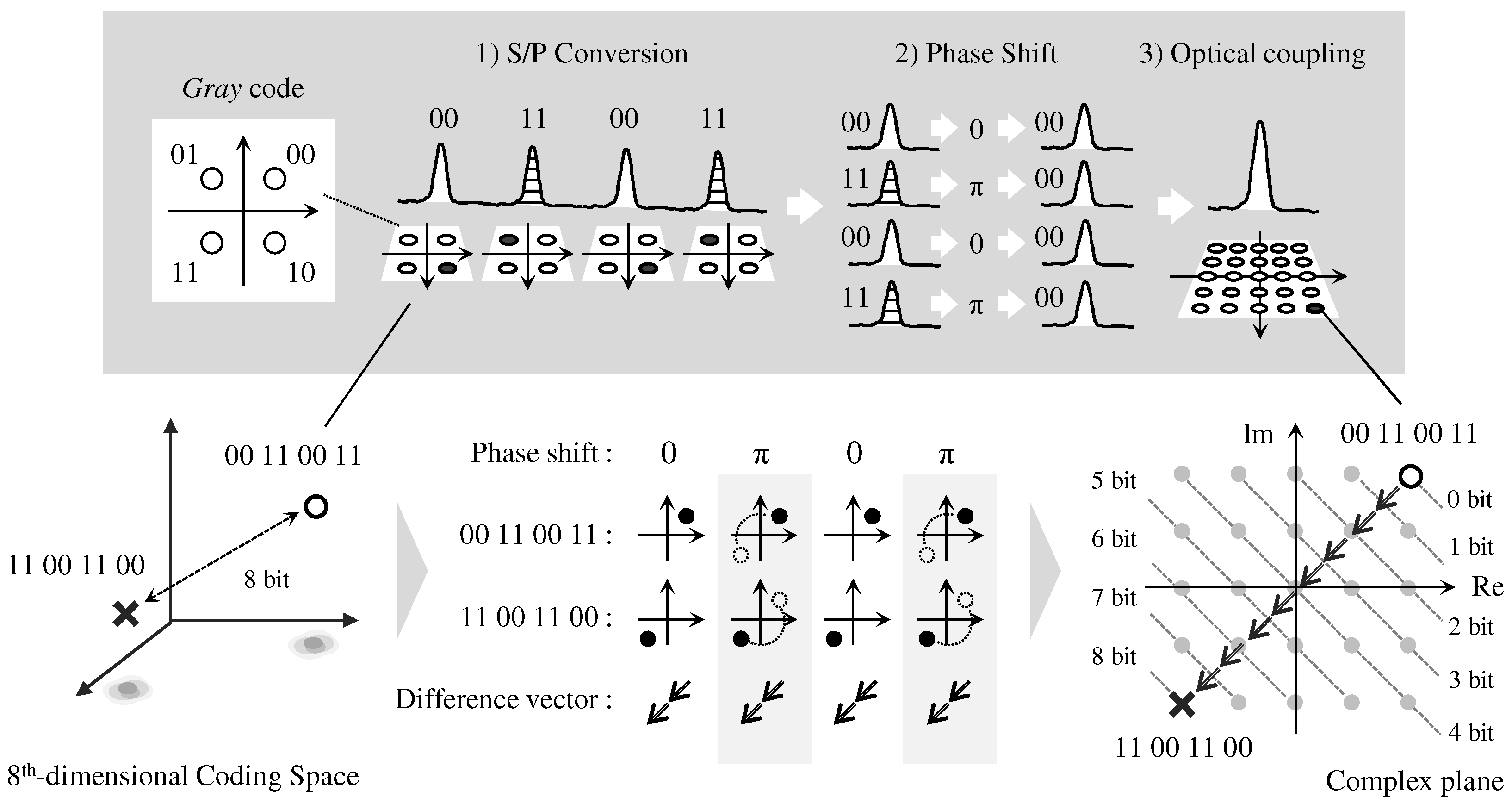
Figure 1 illustrates the operating principles of the optical comparator for QPSK modulation. The proposed comparator is defined for a particular 8-bit code which consists of four successive QPSK symbols; the designed code is named as “comparator code” in this paper. The main purpose of the comparator is to calculate comparison results based on the comparator code. When an arbitrary 8-bit code is injected into the comparator, our scheme yields an optical symbol whose constellation reflects the Hamming distance between the arbitrary 8-bit code and the comparator code. In this context, the Hamming distance is derived as:
where and are n-bit code words, and the Hamming distance provides the number of coefficients in which they differ.
The proposed comparator is designed for four successive QPSK symbols, and their constellation is given in the form of a code. In this code, two adjacent constellations differ in only one bit, and the most-significant-bit and least-significant-bit contribute to the quadrature and in-phase component in the complex plane. The proposed comparator requires three operational steps, as follows:
- S/P conversion: to convert serially-successive symbols into four parallel symbols.
- Phase shift: to rotate the phases in each parallel symbol; the amounts of the phase rotation are determined according to the comparator code to convert their original constellations into a first quadrant in each QPSK symbol, which corresponds to a “00” constellation in code.
- Optical coupling: to yield a complex symbol from four parallel symbols optically.
As an example, an optical comparator designed for a “00 11 00 11” code (e.g., a “00 11 00 11” comparator) is considered. According to the design concept, in the comparator, four phase-rotations for each QPSK symbol are set at 0, , 0, and , respectively. By the phase rotations, every constellation in “00 11 00 11” code will be converted into a “00” constellation. When a “00 11 00 11” signal is injected into the comparator, the comparator generates the coupled symbol whose constellation is located at the vector sum of four “00” constellations in the complex plane; the constellation is named as “ ” in this paper. On the other hand, when a “11 00 11 00” signal is assumed, the set of the (0, , 0, ) phase-shift contributes to rotate their constellations from (11, 00, 11, 00) to (11, 11, 11, 11). As a result, the coupled symbol has a constellation corresponding to the vector sum of four “11” constellations. In this constellation, the distance from the base constellation coincides with the Hamming distance of , because the difference vectors in each symbol, which are based on each symbol of the comparator code, can be surely aligned in a direction inclined by a angle with respect to the horizontal axis in the complex plane. Therefore, the comparator provides the constellation having the comparison result against an arbitrary 8-bit code.
3. Experimental Setup
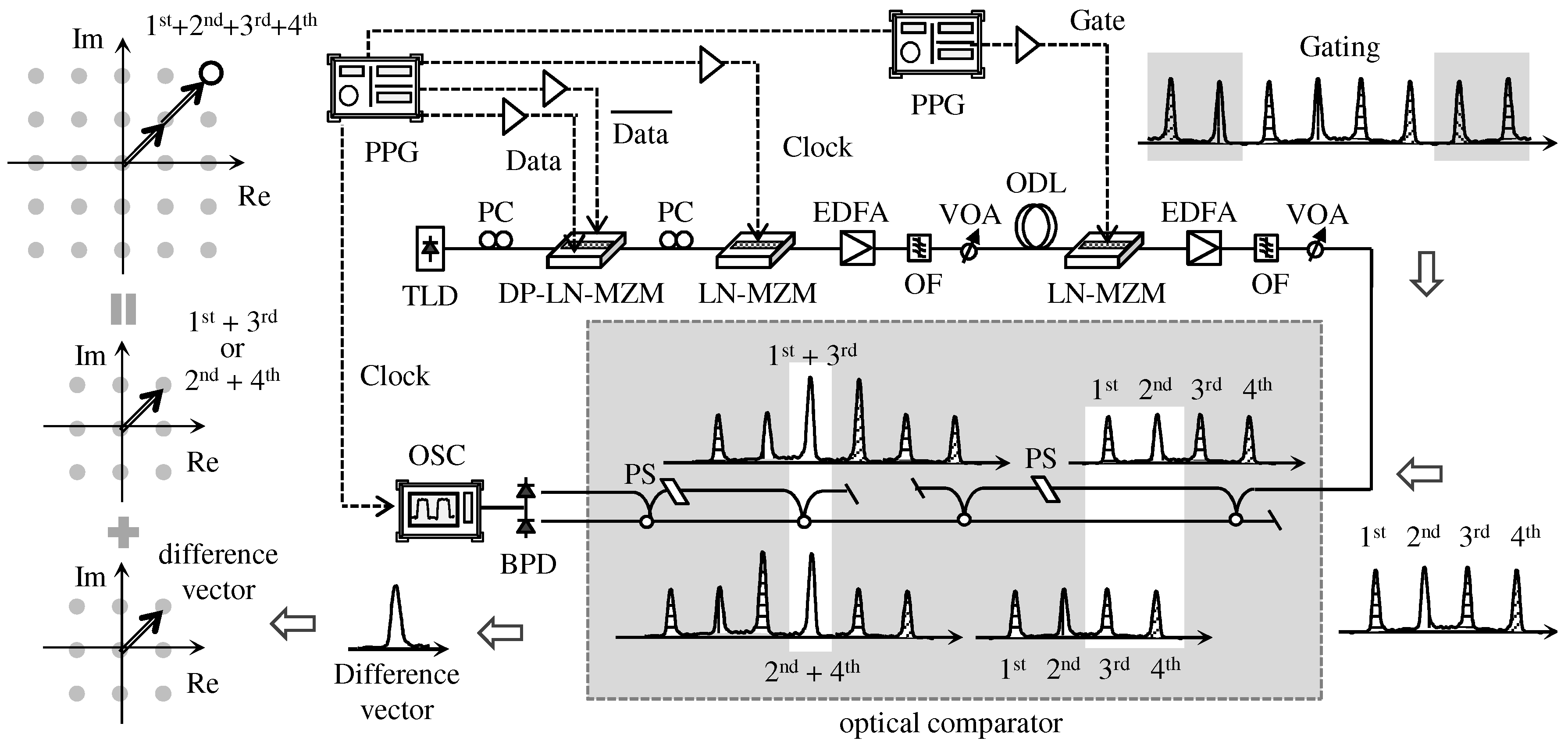
Figure 2 shows the experimental setup of an 8-bit optical comparator. The experimental setup mainly consisted of two components: (A) a QPSK signal generator with optical gate and (B) an optical comparator. The QPSK generator utilizes a tunable laser diode (TLD) (Santec, Tokyo, Japan), pulse pattern generator (PPG) (Anritsu, Kanagawa, Japan), lithium-niobate Mach-Zehnder modulator (LN-MZM) (Sumicem, Tokyo, Japan), and dual-parallel LN-MZM (Sumicem, Tokyo, Japan), respectively. In the generator, a probe light at 1550 nm was generated from the TLD, and the probe was QPSK modulated by using the dual-parallel LN-MZM and the PPG with a pseudo random binary sequence (PRBS) at 10.72 Gbaud. The QPSK signal was then return-to-zero (RZ) modulated by the second LN-MZM driven by the PPG with a 10.72 GHz clock. The optical gate consisted of an LN-MZM and a PPG. The generated QPSK RZ-signal was injected into the third LN-MZM, and four successive QPSK symbols were selected from PRBS by using the second PPG with a 400 ps gate pulse. Then, the selected symbols were injected into the following optical comparator.
The optical comparator comprised two serially cascaded DLIs. The first and second DLIs had 5 and 10 GHz of free spectrum ranges (FSRs), respectively. In the four QPSK symbols at 10 Gbaud, the first and third symbols were optically overlapped in the 5 GHz DLI as well as the second and fourth symbols. The overlapped first + third and second + fourth symbols were then overlapped in the following 10 GHz DLI. As a result, the successive QPSK symbols were converted in parallel and optically coupled, and then the coupled symbol was detected at a following balanced photo detector (BPD).
In this experiment, the author prepared four types of optical comparators to set the phase shifters in each DLI. Each DLI had only one phase shifter on one side of delay line. The optical comparators for “00 00 00 00”, “11 00 11 00”, “11 10 10 00”, and “00 10 01 00” code were arranged by utilizing sets of the (0, 0, 0, 0), (, 0, , 0), (, /2, /2, 0), and (0, /2, 3/2, 0) phase-shifts. In each DLI, the phase shifter offered 0, , , and phase-shift amounts in the condition that the applied voltage was set at 2.3, 2.8, 3.2, and 3.7 V for the 5 GHz DLI, and 0.6, 1.2, 1.8, and 2.4 V for the 10 GHz DLI, respectively. Table 1 summarizes the applied voltage of the phase shifters in each DLI against the four comparators.
4. Experimental Results
4.1. Fundamental Property
The author experimentally evaluated the fundamental properties of the optical comparator. First, the impulse response was evaluated by using an optical short-pulse. The pulse was generated by a mode-locked laser diode emitting at 1550 nm wavelength, which had a 9.2 ps full width at half maximum (FWHM). Figure 3 shows an impulse response of the comparator: (a) input pulse and (b) output pulse train. In this figure, the short pulse is separated into four parts through the two DLIs, and the four pulses appear at equal intervals of time. A 93 ps time duration between first and second pulses offered 10.72 GHz of FSR, and 199 ps (93 ps + 106 ps) time duration between first and third pulses offered 5.03 GHz of FSR.
Then, the transmission spectra were evaluated with an amplified spontaneous emission (ASE) light. Figure 4 shows the transmission spectrum of the “00 00 00 00”, “11 00 11 00”, “11 10 10 00”, and “00 10 01 00” comparators. In Figure 4a, as the “00 00 00 00” spectrum laterally shifted by 0.04 nm to a long-wavelength side, it exactly overlapped the “11 00 11 00” spectrum. The wavelength difference of 0.04 nm corresponds a half of a wavelength interval at 10 GHz (=0.08 nm/2), which is related to a phase difference at 10 GHz DLI between “00 00 00 00” and “11 00 11 00” comparators. Similarly, in Figure 4b, the “11 10 10 00” spectrum exactly overlapped the “00 10 01 00” spectrum with a 0.04 nm shift, which corresponds to a phase amount between “11 10 10 00” and “00 10 01 00” comparators.
4.2. Optical Comparison Operation
The author experimentally demonstrated an 8-bit optical comparison operation to evaluate the constellations obtained from the four comparators when several patterns of 8-bit code, consisting of four QPSK symbols, were injected into the comparators. In this experiment, the author previously evaluated the constellation of either the first + third or second + fourth symbols. Based on the situation, the coupled symbols were detected by a BPD, which gave a difference vector of the signal between the first + third and second + fourth symbols. Here, as we know the pattern of either the first + third or second + fourth symbols, the other constellation can be estimated by using the difference vector. Consequently, from the vector sum of the obtained first + third and second + fourth constellations, the constellation for the given 8-bit code was achieved.
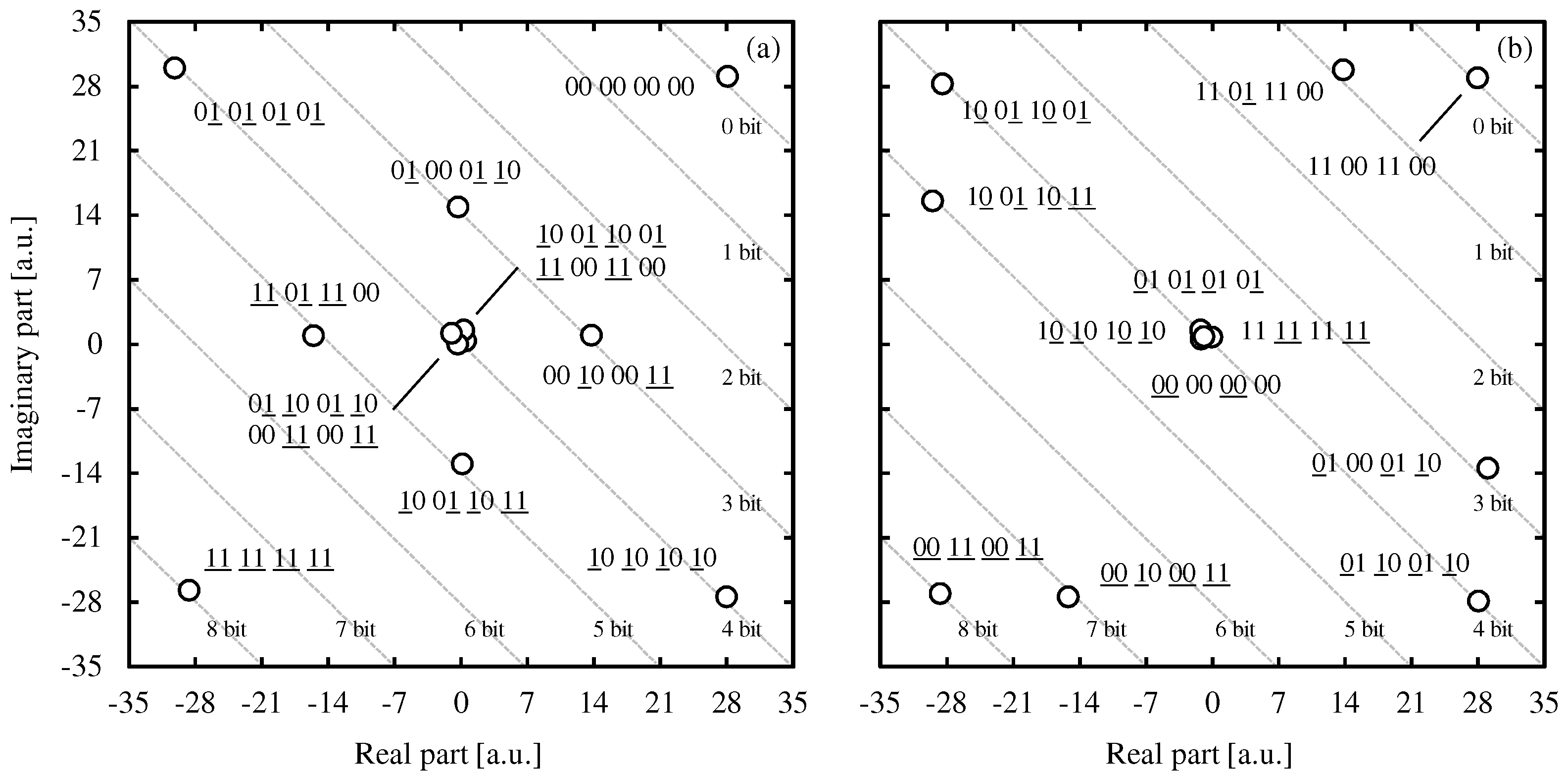
Figure 5 shows the obtained constellations of the “00 00 00 00” and “11 00 11 00” comparators. In this case, twelve 8-bit codes were injected into the two comparators, whose patterns were “00 00 00 00”, “01 00 01 10”, “00 10 00 11”, “10 01 10 01”, “11 00 11 00”, “01 10 01 10”, “00 11 00 11”, “01 01 01 01”, “10 10 10 10”, “11 01 11 00”, “10 01 10 11”, and “11 11 11 11”, respectively. In the case of the “00 00 00 00” comparator, every pattern was divided into five classes in terms of its distance of , where is a given 8-bit code. The twelve 8-bit codes were classified as follows:
- : 00 00 00 00;
- : 01 00 01 10, 00 10 00 11;
- : 10 01 10 01, 11 00 11 00, 01 10 01 10, 00 11 00 11, 01 01 01 01, 10 10 10 10;
- : 11 01 11 00, 10 01 10 11;
- : 11 11 11 11.
As in Figure 5a, all Hamming distances were accurately equal to the distance from the base-constellation in the complex plane. As an example, the “00 00 00 00” constellation corresponds to the base constellation due to its design concept. Meanwhile, the two constellations of “01 00 01 10” and “00 10 00 11”, whose Hamming distance is given by 3, were located 3-bit length away from the base constellation. Furthermore, the “11 11 11 11” constellation was located at the farthest position. The distance coincides with the Hamming distance of .
Similarly, in Figure 5b, the “11 00 11 00” comparator generates the constellations to be located in conformity with a Hamming distance based on the “11 00 11 00” code. In particular, the constellations whose patterns are similar to “11 00 11 00” were located near the base constellation, in contrast, the constellations having different patterns from “11 00 11 00” were located away from the base constellation. As an example, the “11 00 11 00” constellation, which is completely equal to the comparator code, was at the base constellation: . Additionally, the “00 11 00 11” constellation, which is completely different from the comparator code, was located at furthest position in the complex plane: .
Figure 6 shows the constellations of the “11 10 10 00” and “00 10 01 00” comparators with eleven 8-bit codes of “00 00 01 01”, “10 10 00 00”, “00 01 01 01”, “10 10 00 10”, “10 01 10 11”, “11 11 10 10”, “10 11 10 10”, “01 01 11 11”, “01 01 01 11”, “01 11 11 11”, and “11 11 11 10”. In both cases, it is shown that constellations similar to the comparator codes, which were “11 10 10 00” and “00 10 01 00”, were located at near the base constellation. Similarly, constellations different from the comparator codes were located away from the base constellation. From the results above, all constellations were at a position in conformity with the Hamming distance based on each comparator code: “11 10 10 00” and “00 10 01 00”. Therefore, it is shown that the author experimentally demonstrated the feasibility of the optical comparison operation for 8-bit code at 10 Gbaud.
5. Discussion
The important findings in this study are: (1) the optical comparator designed for a “00 00 00 00” code, which consists of a successive four QPSK symbols, yielded an optical symbol whose constellation was located in conformity with a Hamming distance based on the “00 00 00 00” code. (2) Three additional comparators were designed, whose code words were “11 00 11 00”, “11 10 10 00”, and “00 10 01 00”, and same results were obtained. Therefore, it is concluded that the proposed comparator can be designed for an arbitrary 8-bit code, and it offers the comparison result based on the designed code.
Additionally, the author will discuss the feasibility from a point of a practical view: (i) high-order modulation, (ii) code length, and (iii) nonlinear effects. According to the operating principles, the comparator can be utilized for rotationally-symmetric modulations, such as 8-PSK and 16-PSK, since all constellations in the modulations are allowed to exchange each position by phase shift. Similarly, if it is assumed that the additional DLIs are further cascaded, the length of code word can be expanded to an arbitrary bit length. Furthermore, by using an optical compensator for nonlinear effects, it is considered that the comparator can minimize the effect of nonlinear phase noise. Considering the points mentioned above, it is concluded that the proposed comparator can provide highly extensible operation for actual communication systems.
Funding
This research was supported by The Asahi Glass Foundation and The Telecommunications Advancement Foundation.
Acknowledgments
The author would like to thank Hiroyuki Uenohara of Tokyo Institute of Technology for assistance with the experimental installation and helpful discussions.
Conflicts of Interest
The author declares no conflict of interest.
Abbreviations
The following abbreviations are used in this manuscript:
| OOK | On–Off Keying |
| PSK | Phase-Shift Keying |
| QPSK | Quadrature Phase-Shift Keying |
| DLI | Delay Line Interferometer |
| TLD | Tunable Laser Diode |
| PPG | Pulse Pattern Generator |
| LN-MZI | Lithium-Niobate Mach-Zehnder Modulator |
| PRBS | Pseudo Random Binary Sequence |
| RZ | Rreturn-to-Zero |
| FSR | Free Spectrum Range |
| BPD | Balanced Photo Detector |
| FWHM | Full Width at Half Maximum |
| ASE | Amplified Spontaneous Emission |
References
- Urata, R.; Nakahara, T.; Takenouchi, H.; Segawa, T.; Ishikawa, H.; Ohki, A.; Sugiyama, H.; Nishihara, S.; Takahashi, R. 4 × 4 optical packet switching of asynchronous burst optical packets with a prototype, 4 × 4 label processing and switching sub-system. Opt. Express 2010, 18, 15283–15288. [Google Scholar] [CrossRef] [PubMed]
- Segawa, T.; Ibrahim, S.; Nakahara, T.; Muranaka, Y.; Takahashi, R. Low-Power Optical Packet Switching for 100-Gb/s Burst Optical Packets With a Label Processor and 8 × 8 Optical Switch. J. Lightw. Technol. 2016, 34, 1844–1850. [Google Scholar] [CrossRef]
- Martinez, J.M.; Herrera, J.; Ramos, F.; Marti, J. All-Optical Address Recognition Scheme for Label-Swapping Networks. IEEE Photonics Technol. Lett. 2006, 18, 151–153. [Google Scholar] [CrossRef]
- Kehayas, E.; Seoane, J.; Liu, Y.; Martinez, J.M.; Herrera, J.; Holm-Nielsen, P.V.; Zhang, S.; McDougall, R.; Maxwell, G.; Ramos, F.; et al. All-Optical Network Subsystems Using Integrated SOA-Based Optical Gates and Flip-Flops for Label-Swapped Networks. IEEE Photonics Technol. Lett. 2006, 18, 1750–1752. [Google Scholar] [CrossRef]
- Suzuki, M.; Uenohara, H. Investigation of all-optical error detection circuit using SOA-MZI-based XOR gates at 10 Gbit/s. Electron. Lett. 2009, 45, 224–225. [Google Scholar] [CrossRef]
- Aikawa, Y.; Shimizu, S.; Uenohara, H. Demonstration of All-Optical Divider Circuit Using SOA-MZI-Type XOR Gate and Feedback Loop for Forward Error Detection. J. Lightw. Technol. 2011, 15, 2259–2266. [Google Scholar] [CrossRef]
- Aikawa, Y.; Uenohara, H. Demonstration of Optical FEC Coding Scheme with Convolutional Code Consisting of a Single Source. IEEE Photonics Technol. Lett. 2017, 29, 165–168. [Google Scholar] [CrossRef]
- Kostinski, N.; Kravtsov, K.; Prucnal, P.R. Demonstration of an All-Optical OCDMA Encryption and Decryption System With Variable Two-Code Keying. IEEE Photonics Technol. Lett. 2008, 20, 2045–2047. [Google Scholar] [CrossRef]
- Fok, M.P.; Prucnal, P.R. All-optical encryption based on interleaved waveband switching modulation for optical network security. Opt. Lett. 2009, 34, 1315–1317. [Google Scholar] [CrossRef] [PubMed]
- Kim, J.H.; Byun, Y.T.; Jhon, Y.M.; Lee, S.; Woo, D.H.; Kim, S.H. All-optical half adder using semiconductor optical amplifier based devices. Opt. Commun. 2003, 218, 345–349. [Google Scholar] [CrossRef]
- Kumar, S.; Willner, A.E.; Gurkan, D.; Parameswaran, K.R.; Fejer, M.M. All-optical half adder using an SOA and a PPLN waveguide for signal processing in optical networks. Opt. Express 2006, 14, 10255–10260. [Google Scholar] [CrossRef] [PubMed]
- Poustie, A.J.; Blow, K.J.; Kelly, A.E.; Manning, R.J. All-optical full adder with bit-differential delay. Opt. Commun. 1999, 168, 89–93. [Google Scholar] [CrossRef]
- Martinez, J.M.; Herrera, J.; Ramos, F.; Marti, J. All-optical correlation employing single logic XOR gate with feedback. Electron. Lett. 2006, 42, 1–2. [Google Scholar] [CrossRef]
- Rasras, M.S.; Kang, I.; Dinu, M.; Jaques, J.; Dutta, N.; Piccirilli, A.; Cappuzzo, M.A.; Chen, E.Y.; Gomez, L.T.; Foy, A.W.; et al. A Programmable 8-bit Optical Correlator Filter for Optical Bit Pattern Recognition. IEEE Photonics Technol. Lett. 2008, 20, 694–696. [Google Scholar] [CrossRef]
- Khaleghi, S.; Yilmaz, O.F.; Chitgarha, M.R.; Tur, M.; Ahmed, N.; Nuccio, S.R.; Fazal, I.M.; Wu, X.; Haney, M.W.; Langrock, C.; et al. High-Speed Correlation and Equalization Using a Continuously Tunable All- Optical Tapped Delay Line. IEEE Photonics J. 2012, 4, 1220–1235. [Google Scholar] [CrossRef]
- Chitgarha, M.R.; Khaleghi, S.; Yilmaz, O.F.; Tur, M.; Haney, M.W.; Lan-grock, C.; Fejer, M.M.; Willner, A.E. Coherent correlator and equalizer using a reconfigurable all-optical tapped delay line. Opt. Lett. 2013, 38, 2271–2273. [Google Scholar] [CrossRef] [PubMed]
- Wang, Y.; Zhang, X.; Dong, J.; Huang, D. Simultaneous demonstration on all-optical digital encoder and comparator at 40 Gb/s with semiconductor optical amplifiers. Opt. Lett. 2007, 15, 15080–15085. [Google Scholar] [CrossRef]
- Scaffardi, M.; Lazzeri, E.; Poti, L.; Bogoni, A. All-Optical Comparator Based on Cross Gain Modulation in Semiconductor Optical Amplifiers. In Proceedings of the Optical Fiber Communication Conference/National Fiber Optic Engineers Conference (OFC/NFOEC) 2008, San Diego, CA, USA, 24–28 February 2008; p. JWA79. [Google Scholar]
- Li, P.; Sang, L.; Zhao, D.; Fan, Y.; Shore, K.A.; Wang, Y.; Wang, A. All-Optical Comparator With a Step-Like Transfer Function. J. Lightw. Technol. 2017, 35, 5034–5040. [Google Scholar] [CrossRef]
- Nakarmi, B.; Uddin, M.R.; Won, Y.H. Realization of All-Optical Digital Comparator Using Single Mode Fabry–Perot Laser Diodes. J. Lightw. Technol. 2011, 29, 3015–3021. [Google Scholar] [CrossRef]
- Yang, L.; Guo, C.; Zhu, W.; Zhang, L.; Sun, C. Demonstration of a Directed Optical Comparator Based on Two Cascaded Microring Resonators. IEEE Photonics Technol. Lett. 2015, 27, 809–812. [Google Scholar] [CrossRef]
- Weinstock, T.; Ehrlichman, Y.; Amrani, O. Electrooptical Comparator: From Formula to Implementation. J. Lightw. Technol. 2017, 35, 4056–4066. [Google Scholar] [CrossRef]
- Aikawa, Y. Optical Comparator for 4-Bit and 6-Bit QPSK-Modulated Signals by Using Optical Delayed Interferometer. IEEE Photonics J. 2018, 10, 7800711. [Google Scholar] [CrossRef]
Figure 1.
Operating principles of the optical comparator for an 8-bit quadrature phase-shift keying (QPSK) signal. In this figure, the comparator is designed for a “00 11 00 11” code to set their phase shifts at , and the working example is illustrated when a “11 00 11 00” signal is input. It is shown that the Hamming distance of corresponds to the distance of both constellations.

Figure 2.
Experimental setup of an optical comparator for 8-bit QPSK signal. In this figure, the comparator comprises a serially cascaded two delay line interferometers (DLIs), whose FSRs are 5 and 10 GHz, respectively. The comparator generates a coupled symbol from four QPSK symbols with predetermined phase rotations. BPD: balanced photo detector; DP-LN-MZM: dual-parallel lithium-niobate Mach-Zehnder modulator; EDFA: erbium-doped fiber amplifier; ODL: optical delay line; OF: optical filter; OSC: oscilloscope; PC: polarization controller; PPG: pulse pattern generator; PS: phase shifter; TLD: tunable laser diode; VOA: variable optical attenuator.

Figure 3.
Impulse response of the 8-bit optical comparator: (a) Input pulse; (b) Output of optical comparator. In this figure, the impulse is separated into four parts, and four pulses are arranged at uniform intervals. The time intervals in each pulse offered 5.03 and 10.72 GHz of FSR in each DLI.
Figure 3.
Impulse response of the 8-bit optical comparator: (a) Input pulse; (b) Output of optical comparator. In this figure, the impulse is separated into four parts, and four pulses are arranged at uniform intervals. The time intervals in each pulse offered 5.03 and 10.72 GHz of FSR in each DLI.

Figure 4.
Transmission spectra of the 8-bit optical comparator: (a) “00 00 00 00” and “11 00 11 00” comparator. (b) “11 10 10 00” and “00 10 01 00” comparator. In these figures, the “00 00 00 00” and “11 10 10 00” spectra exactly overlap the “11 00 11 00” and “00 10 01 00” spectra with 0.04 nm wavelength shift, which correspond to a phase different at 10 GHz DLI.
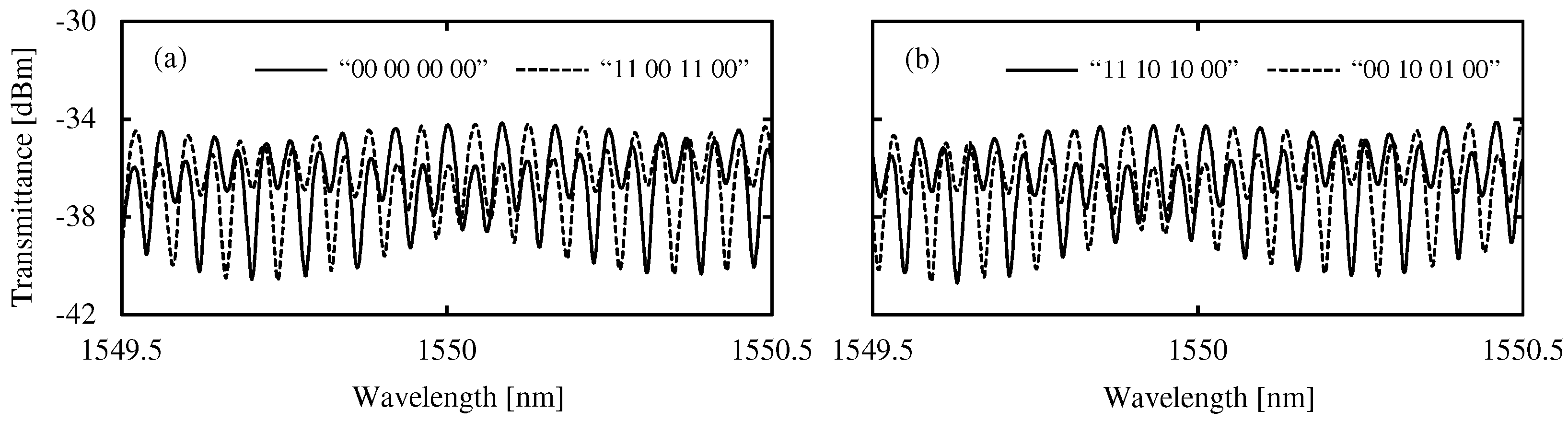
Figure 5.
Constellations of the 8-bit optical comparator: (a) “00 00 00 00” comparator. (b) “11 00 11 00” comparator. In these figures, all constellations are located in conformity with the distance based on the comparator codes “00 00 00 00” and “11 00 11 00”, respectively. The inconsistent bits with the comparator code are underlined in each comparator.

Figure 6.
Constellations of the 8-bit optical comparator: (a) “11 10 10 00” comparator. (b) “00 10 01 00” comparator. In these figures, all constellations are located in conformity with the distance based on the comparator codes “11 10 10 00” and “00 10 01 00”, respectively. The inconsistent bits with the comparator code are underlined in each comparator.


Table 1.
The applied voltages of phase shifters against four types of optical comparators.
| Comparator Code | Applied Voltage in PS (V) | Phase Shifts in Each Symbol | ||||
|---|---|---|---|---|---|---|
| 5GHz DLI | 10GHz DLI | 1st | 2nd | 3rd | 4th | |
| 00 00 00 00 | 2.3 (=0) | 0.6 (=0) | 0 | 0 | 0 | 0 |
| 11 00 11 00 | 2.3 (=0) | 1.8 (=) | 0 | 0 | ||
| 11 10 10 00 | 2.8 (=/2) | 1.2 (=/2) | /2 | /2 | 0 | |
| 00 10 01 00 | 2.8 (=/2) | 2.4 (=3/2) | 0 | /2 | 3/2 | 0 |
© 2018 by the author. Licensee MDPI, Basel, Switzerland. This article is an open access article distributed under the terms and conditions of the Creative Commons Attribution (CC BY) license (http://creativecommons.org/licenses/by/4.0/).
Share and Cite
MDPI and ACS Style
Aikawa, Y. Optical Comparison Operation for 8-Bit QPSK-Modulated Signal by Using Serially-Cascaded Delay Line Interferometer. Appl. Sci. 2018, 8, 1440. https://doi.org/10.3390/app8091440
AMA Style
Aikawa Y. Optical Comparison Operation for 8-Bit QPSK-Modulated Signal by Using Serially-Cascaded Delay Line Interferometer. Applied Sciences. 2018; 8(9):1440. https://doi.org/10.3390/app8091440
Chicago/Turabian StyleAikawa, Yohei. 2018. "Optical Comparison Operation for 8-Bit QPSK-Modulated Signal by Using Serially-Cascaded Delay Line Interferometer" Applied Sciences 8, no. 9: 1440. https://doi.org/10.3390/app8091440
Note that from the first issue of 2016, this journal uses article numbers instead of page numbers. See further details here.