Molecular Controlling the Transport Properties for Benzothiadiazole-Based Hole Transport Materials


1
Department of Applied Physics, Xi’an University of Technology, Xi’an 710054, China
2
College of Science, Northeast Forestry University, Harbin 150040, China
3
Chemical Industry and Material College, Heilongjiang University, Harbin 150080, China
4
Department of Physics, Liaoning University, Shenyang 110036, China
*
Authors to whom correspondence should be addressed.
Appl. Sci. 2018, 8(9), 1461; https://doi.org/10.3390/app8091461
Submission received: 21 July 2018
/
Revised: 11 August 2018
/
Accepted: 11 August 2018
/
Published: 25 August 2018
(This article belongs to the Special Issue Next Generation Photovoltaic Solar Cells)
Abstract
:Three experimental hole transport materials containing fluorine-substituted benzothiadiazole-based organic molecules (Jy5–Jy7) have been studied to explore the relationship between photoelectric performances and the core structures of hole transport materials (HTM). By employing density functional theory (DFT) and time-dependent density functional theory (TD-DFT), it was found that the substitution of the hydrogen atom by fluorine atom in the core structure can significantly boost the hole mobility; and the replacement of core structure from electron-withdrawing group to electron-donating group has strong influence on the increment of LUMO level energy, ability to preventing electron-backflow, molecular stability and oscillator strength of HTM molecules. We hope our investigation can provide theoretical guidance to reasonably optimize HTM molecules for perovskite solar cells.
1. Introduction
Nowadays, the continuous consumption of fossil fuels and the sustained environmental crisis have prompted people to seek for new sustainable and clean energy sources. Solar energy is an ideal candidate, not only because of its tremendous reserve, but also it can be directly converted to be electricity through solar cell devices. Recently, organic solar cells (OSC), such as conductive polymers, small molecules, fullerene-based and non-fullerene-based system [1,2,3], have attracted much attention due to the advantages of low cost, easy synthesis and structural tuning performance etc. [2,3]. Higher power conversion efficiency (PCE) and stability of OSC have also been reported [2], which provide a channel to efficient utility of solar energy in a clean and environmentally friendly way. Meanwhile, organic–inorganic halide perovskite solar cells (PVSCs) have been paid extensive attention owing to many their advantages, such as intense broad-band absorption (covering UV and near infrared regions), photo-absorption coefficients (ten times bigger than organic dyes), low-band gap (1.25 eV), long charge diffusion lengths (charge transport is about 1 μm) and high charge mobility, et al. [4,5,6] In the last year, PCE of PVSCs has made impressive progress, from 3.8% to a reported 22% [6,7], which have revolutionized the field of photovoltaic technologies. The basic structure of perovskite solar cells is usually three layers (electronic transport layer (titanium dioxide)/perovskite absorption layer/hole transport layer) [8], which are placed between substrate materials (see Supplementary Materials Figure S1). Here, the hole transport material (HTM) plays an indispensable role in PVSCs, and an ideal HTM can increase the short-circuit current density (JSC), open-circuit voltage (VOC) and have a marked impact on the stability of PVSCs [9,10]. Good HTM must indeed exhibit the following features [11,12,13,14]: firstly, a good energy match between HTM molecular orbitals (highest occupied molecular orbital (HOMO) and lowest unoccupied molecular orbital (LUMO)) and contacted interfaces for efficient charge injection; second, high hole transporting properties to reduce charge recombination; stability with characteristics in protection of corrosion and resistance of oxidation. Some HTMs have been reported using spirobifluorenes, conjugated polymers, triphenylamines, triazatruxenes and so on [11]. Although the 2,2′,7,7′-tetrakis (N,N-p-dimethoxy-phenylamino)-9,9′-spirobi fluorine (Spiro-OMe TAD) as HTM is viewed to be a most successful material, there are some shortcomings in the utility of Spiro-OMeTAD [12,13], such as cost-performance, long-term stability and low charge-carrier mobility, etc. As an alternative to Spiro-OMeTAD, carbazole-based material (X51) was designed and used as HTM owing to easy substitution with functional groups to control optical and electrical properties [13]. From the viewpoint of molecular design, a new hole transport material Jy5 was experimentally reported on by introduction of benzothiadiazole (BT). Based on HTM X51, and mono-fluorinated benzothiadiazole (BT) and difluorinated BT (FBT) have been used as core structure to design new HTM Jy6 and Jy7 [14] (the core structures of Jy5–Jy7 are represented by the red groups, and the chemical structures of them can be found in Figure 1). Experimentally, the designed Jy6 obtains high open circuit voltage (VOC) for 1.06 V, large short-circuit current density (JSC) for 21.39 mA/cm2 and outstanding fill factor (FF) up to 81%, which leads to the PCE of 18.54% for the Jy6 system.
The concept of replacing atom with thiophene and conjugated group has been well-established in the design of photovoltaic materials [15,16], and strategy of manipulation on alkoxyl-substituted benzodithiophene or conjugated bridge with electron deficient groups can improve hole mobilities and energy levels and affect the device performance because of intermolecular interactions and orientation correlations. Stimulated by the experimental report on HTM molecules [14], three new HTM molecules Jy8, Jy9 and Jy10 were designed on the basis of the structures of Jy5–Jy7. For Jy8, we employed the benzodithiophene (BDT) as the core structure (red group in Figure 1); for Jy9, dithienosilole (DTS) was used as core structure; while for Jy10, alkylthienyl-substituted benzo[1,2-b:4,5-b’]dithiophene (TBDT) was taken as core structure. For the three molecules Jy5–Jy7, the core structures are the electron-withdrawing groups, and the core structures of Jy8–Jy10 are the electron-donating groups. According to the work of Chen et al. [17], the BDT acts as electron donor and BT as electron acceptor in their investigated molecules. The work of Yun el al. [18] shows that the DTS is the electron donor, and the BT is the electron acceptor in their HTM molecule, and the TBDT was used as the electron-donating group in the HTM molecule [19]. Contrarily, for Jy5–Jy7 the core structure BT acts as the electron-withdrawing unit in molecular frame, and the introduction of fluorine has increased the electron-withdrawing ability of BT. The current aim of our investigation is to study the relationships between the photoelectric performances of HTM molecules and to reveal the influence of the electron-donating/electron-withdrawing core structures on transport ability of HTM.
2. Computational Details
The ground-state, cation and anion geometry structures of the Jy5–Jy10 have been optimized by using the density functional theory (DFT) method [20] with B3LYP functional [21] at the 6-31G(d) basis set associated with C-PCM model [22] in dichloromethane solvent. Based on the optimized structures of Jy5–Jy10, we calculated their UV-Vis absorption spectra by employing the time-dependent density functional theory (TD-DFT) method [23] with CAM-B3LYP functional [24] at 6-31G(d) level associated with C-PCM model in dichloromethane solvent. DFT calculations were used to study the excited state features of dye-sensitized solar cells (DSSCs) [25], the photo physical properties of expanded bacteriochlorins [26] and the charge transport in solar cell [27,28]. To obtain the density of state (DOS) and partial density of states (PDOS) of six investigated molecules, the Multiwfn 3.4.1 package [29] was employed. For further investigating the hole mobility of six molecules, the Marcus theory was employed [30,31,32,33,34].
3. Results and Discussion
3.1. Ground-State Geometries and Frontier Molecular Orbitals
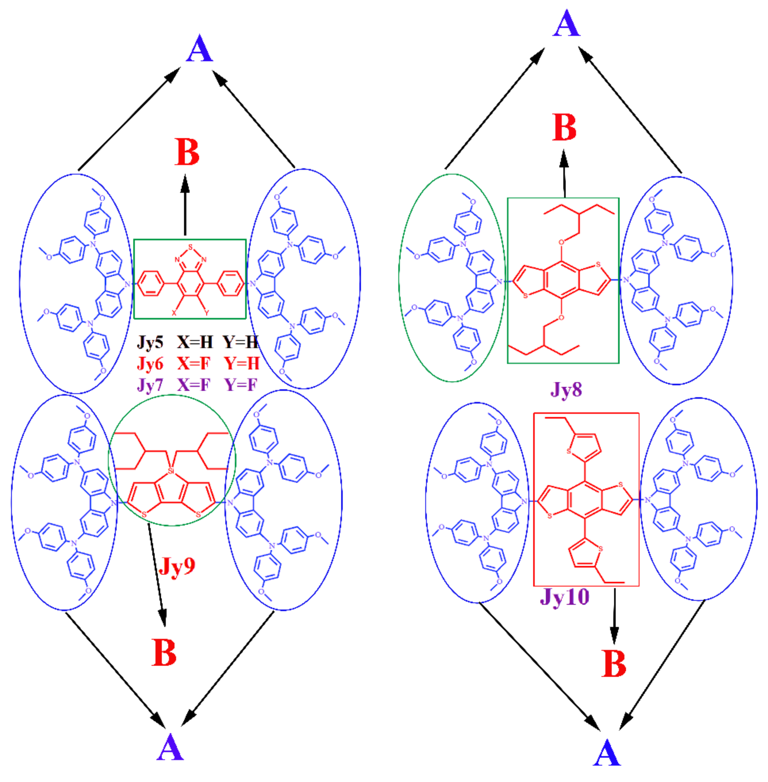
The chemical structures of three experimental molecules Jy5–Jy7 and three designed molecules Jy8–Jy10 have been presented in Figure 1. As mentioned above, the differences of six studied molecules are their core structures (represented by red groups in Figure 1). In order to clearly explain the functions of each group, we defined the core structure of each molecule as B, and defined the structure of the two sides of each molecule as A. The definition of the fragment is shown in Figure 2. By employing DFT/B3LYP/6-31G(d) with C-PCM model in dichloromethane solvent, the frontier molecular orbitals (FMOs) energy levels have been calculated, and the results have been listed in Table 1 and Figure 3.
As shown in Table 1, the HOMO level of three experimental molecules Jy5, Jy6 and Jy7 are −4.49 eV, −4.49 eV and −4.50 eV, respectively; the LUMO level of them are −2.55 eV, −2.59 eV and −2.62 eV, respectively. The energy gap of HTM can be estimated by ; therefore, the of Jy5–Jy7 are calculated to be 1.94 eV, 1.90 eV and 1.88 eV, respectively. The computational results show that both HOMO levels and LUMO levels of Jy5−Jy7 are very close, which leads to small differences in the energy gaps between the three molecules. This result shows that the introduction of fluorine in the core structures of Jy6 and Jy7 have little influence on FMOs levels and energy gaps of them. For the designed molecule Jy8, Jy9 and Jy10, the HOMO levels are −4.53 eV, −4.53 eV and −4.52 eV, respectively; the LUMO levels are −1.46 eV, −1.71 eV and −1.70 eV, respectively; and the of them are 3.07 eV, 2.82 eV and 2.82 eV, respectively. It can be seen that the HOMO levels of the three designed molecules are very close. Similarly, there are small differences between the HOMO levels of designed molecules and HOMO levels of experimental parent molecules. The molecular orbital level features can be explained from electron density distribution (Frontier molecular orbital plots) and contribution of molecular orbital (partial density of states (PDOS)) as mentioned below. For the three designed molecules, the LUMO level of Jy8 is the highest, and the LUMO levels of Jy9 and Jy10 are the same. Compared with three experimental molecules, the LUMO levels of three designed molecules have an obviously increase. This means that the substitution of the core structure from the electron-withdrawing group to the electron donating group has little effect on the HOMO level of the studied molecules, but it can significantly increase the LUMO level of the molecule. Compared with experimental molecules, the significant increases of LUMO levels of the three designed molecules lead to notable rises of energy gaps. Taking Jy5 as an example, the of Jy8, Jy9 and Jy10 are raised by 1.13 eV, 0.88 eV and 0.88 eV, respectively, when compared with Jy5.
Matching energies are very important for the occurrence of charge transfer between the different surfaces in accord with enough driving force, as shown in Figure S1 [35]. The energy diagram of the perovskite, TiO2 and six investigated HTM molecules are presented in Figure 3. As shown, the HOMO levels of six molecules are quite close, and they are all higher than the HOMO level of perovskite. The LUMO levels of the designed molecules are obviously raised, compared with the experimental molecules, and the LUMO levels of the six molecules are all higher than that of perovskite.
It is noted that the LUMO level of perovskite is slightly higher than LUMO level of TiO2, which can inject the electron from perovskite to TiO2 successfully. If the HOMO level of HTM is higher than the valence band of perovskite, the hole injection from perovskite to the HTM is advantageous [35]. Meanwhile, if the LUMO level is higher than the conduction band of perovskite, the electron backflow from perovskite to the metal electrodes will be inhibited efficaciously [35,36]. From the Figure 3, it was found that the HOMO levels of six studied molecules are all beneficial for hole injection from perovskite to them, and the LUMO levels of them can prohibit the electron-backflow effectively. Moreover, the LUMO levels of designed molecules Jy8–Jy10 are higher than those of experimental molecules Jy5–Jy7, which can allow the designed molecules to exhibit better blocking effects on electronic reflux. Six studied molecules have similar hole injection abilities, and for the abilities of preventing electron backflow, we can find the following sequence: Jy8 > Jy9 ≈ Jy10 > Jy5 > Jy6 > Jy7. The results show that the replacement of core structures for Jy5–Jy7 from hydrogen atom to fluorine atom has little influence on hole injection and electron backflow. Moreover, it is obvious that the substitution of the central structures from the electron-withdrawing group to the electron-donating group can significantly increase the ability of preventing electron-backflow of HTM molecules.
The FMO plots of molecules were shown in Figure 4. For six molecules, the electronic density of HOMO is mostly concentrated in #A groups of each molecule, and the electronic density of LUMO is mostly concentrated in #B fragments of each molecule. The characteristics of electronic density can explain the results of close energy levels, that is to say, from the electronic density distribution of HOMO (see Figure 4) it was found that the electron densities are located in the two sides of molecular backbone (there are no electron density in core region), meaning no contribution of central cores (BT, FBT and TFBT) region to the HOMO; therefore, there are closed energy levels for the three molecules (JY5–JY7). For LUMO, though electron density resides in the central region, contribution comes from BT, FBT and TFBT cores, and fluorine atom has a little influence on the LUMO. Moreover, for HOMO plots of the investigated molecules, for Jy5, Jy8 and Jy10, their electronic density of HOMO almost belongs to symmetrical characteristics in both sides; while for Jy6, Jy7 and Jy9, the HOMO electronic density distributes asymmetrically on two sides of the molecule. From the distribution of FMO, it was found that the replacement of core structure from the electron-withdrawing group to the electron-donating group will not affect the role of the core structure and the two sides of molecules. The FMOs plots confirm that the #A fragment of each molecule acts as an electron donor and that the B fragment acts as an electron acceptor.
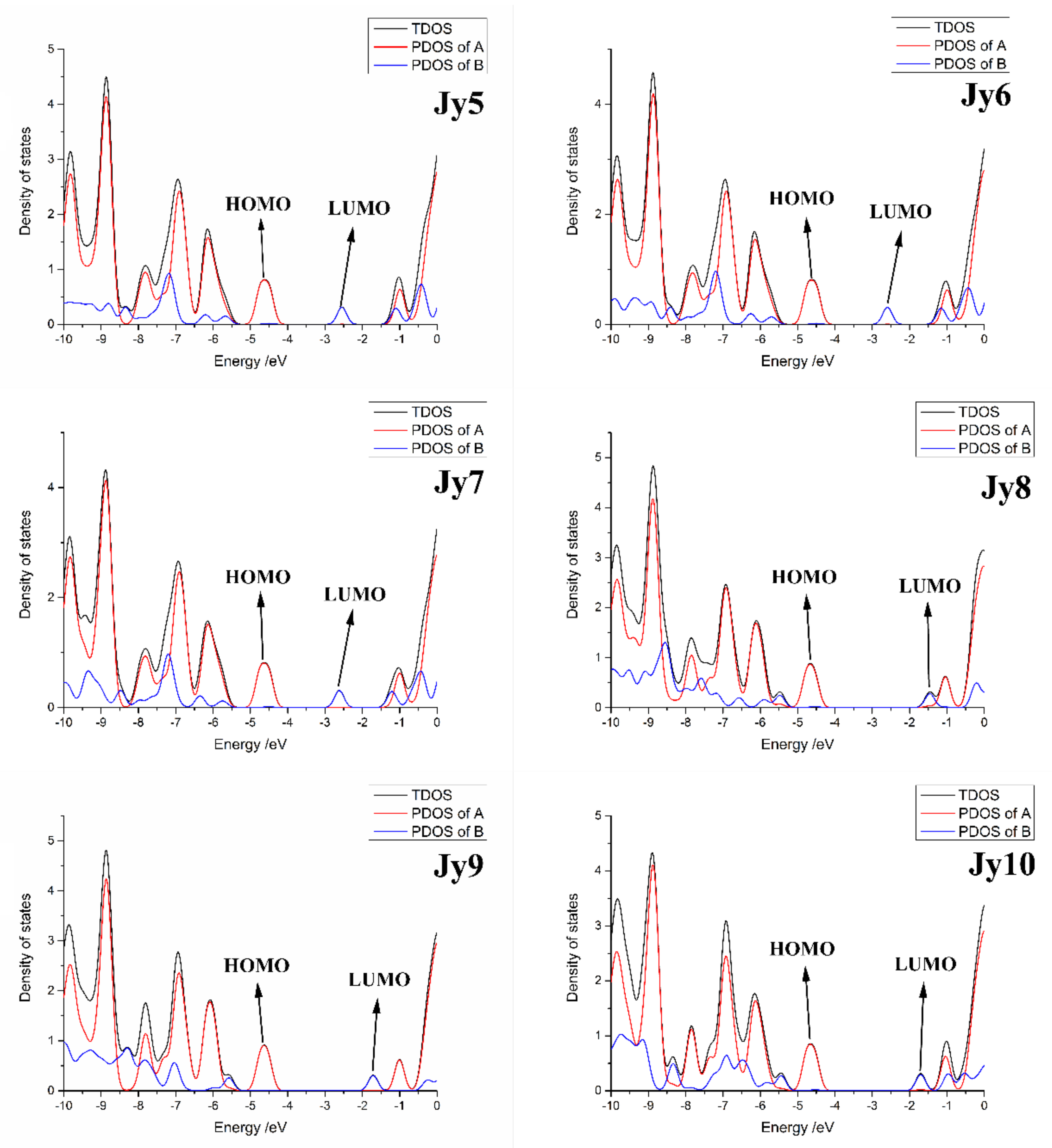
The TDOS and PDOS of the six investigated molecules have been presented in Figure 5. The black line represents the TDOS of the molecule, and the red line and blue line represents the PDOS of defined fragments #A and #B, respectively. The DOS diagram of the six molecules shows that almost all the HOMOs of each molecule are concentrated in the #A fragment, and the LUMO level is almost concentrated in the #B fragment; the PDOS of the #B fragment at the HOMO level is almost zero (central cores have no contribution to HOMO), which supporting the result of electron density distribution (see Figure 4), and the PDOS of the #A fragment at the LUMO level is the same tendency. It is also found that for each of the investigated molecules, fragment #A acts as electron donor, and then fragment B plays the role of electron acceptor.
3.2. Ionization Potentials, Electron Affinities and Absolute Harness
For organic materials, the barrier of charge transfer can be estimated by ionization potentials (IPs) and electron affinities (EAs) [27,36]. In general, the lower IP means the easier hole transfer, and the higher EA is more favorable for electron transfer [37]. Based on the optimized cation and anion geometry structures of the six molecules, we calculated their IPs, EAs and absolute hardness (), as listed in the Table 2.
The calculated IPs are 4.40 eV for Jy5, 4.39 eV for Jy6, 4.41 eV for Jy7, 4.45 eV for Jy8, 4.37 eV for Jy9 and 4.44 eV for Jy10. The six molecules have similar IPs, and among them the Jy9 has the smallest IP, and Jy8 has the biggest IP. The EAs of three experimental molecules are 2.64 eV for Jy5, 2.68 eV for Jy6 and 2.70 eV for Jy7, respectively; for three designed molecules Jy8–Jy10, the EAs of them are 1.66 eV, 1.96 eV and 1.98 eV, respectively. It can be seen that the EAs of the experimental parent molecules Jy5–Jy7 have little differences. Among the three designed molecules, the Jy8 has the smallest EA, and the EAs of Jy9 and Jy10 are adjacent values. Compared with experimental molecules, the three designed molecules have apparent decreased tendency. As mentioned above, the results show that the six studied molecules should have similar hole injection abilities; and the electron injection abilities of six molecules are in the following order: Jy8 < Jy9 ≈ Jy10 < Jy5 < Jy6 < Jy7, which means that the abilities to prevent electron-backflow is Jy8 > Jy9 ≈ Jy10 > Jy5 > Jy6 > Jy7. It was found that for both hole injection abilities and the abilities to prevent electronic backflow, the analysis of FMO and the analysis of IP/EA have the same results. Furthermore, the results also show that the substitution of core structure from electron-withdrawing group to electron-donating group has small influences on hole injection, but it will clearly boost the blocking effect on electron backflow.
Although the stability of PVSCs is related to many parameters and aspects, the absolute hardness () can be used to evaluate the stability of organic molecule, and the absolute hardness is defined by [38]:
The calculated results of have been listed in the Table 2. For experimental parent molecules Jy5–Jy7, the absolute hardness are 0.88 eV, 0.86 eV and 0.86 eV, respectively. The results show that the absolute hardness of three experimental molecules is very similar. As a result of the significant drops of EAs for designed molecules, compared with those of experimental molecules, the of Jy8–Jy10 have evidently increased tendency. As shown in Table 2, the absolute hardness of three designed molecules are 1.40 eV, 1.21 eV and 1.23 eV, respectively. The is the resistance of the chemical potential to change in the number of electrons. So that the more stable organic molecule should possess a larger absolute hardness [39]. The absolute hardness of six molecules shows that the designed molecules Jy8–Jy10 are apparently more stable than original experimental molecules Jy5–Jy7. Among six molecules, the Jy8 has the highest absolute hardness, which means that the Jy8 has the best stabilization in six studied molecules. And the stabilizations of three designed molecules are clearly better than those of experimental molecules. The stability of six molecules are in the following sequence: Jy8 > Jy9 ≈ Jy10 > Jy10 > Jy5 > Jy6 = Jy7. The calculated absolute harness shows that replacing hydrogen by fluorine in the core structure has no obvious effect on the stability of molecules. However, the replacement of the core structure from the electron-withdrawing group to electron-donating group will obviously increase the stability of molecules.
3.3. Reorganization Energy of HTM Molecules
Generally, the charge transfer characteristics of organic materials can be estimated by the reorganization energy ( and ); the lower reorganization energy means the faster charge transport, both of the hole and electron [39]. In theory, we employ the following expression to calculate the hole reorganization and the electron reorganization energy [40,41,42,43]:
In this expression, the is the energy of cation (anion) calculated with the optimized neutral molecule structure; the is the energy of cation (anion) calculated with the optimized cationic (anionic) molecule structure. Correspondingly, the is the energy of neutral molecule calculated with the optimized cationic (anionic) molecule structure; and the is the energy of neutral molecule calculated with optimized neutral molecule structure. We listed the results of calculated λh and λe in the Table 3.
The results in Table 3 show that the λh of six molecules are 0.14 eV for Jy5, 0.15 eV for Jy6, 0.15 eV for Jy7, 0.11 eV for Jy8, 0.17 eV for Jy9 and 0.11 eV for Jy10. The experimental parent molecules Jy5–Jy7 have closed hole reorganization energies. Compared with experimental molecules, the designed molecules Jy8 and Jy10 have lower λh and Jy9 has higher λh. Results show that the introduction of fluorine for Jy5–Jy7 has little influence on hole transport ability, and replacement of core structure from the electron-withdrawing group to the electron-donating group will change the hole transport ability of HTM molecules.
The λe of Jy5–Jy7 are 0.34 eV, 0.35 eV and 0.36 eV, respectively; reorganization energy of Jy8–Jy10 are 0.39 eV, 0.39 eV and 0.42 eV, respectively. Similar to the λh of experimental molecules, the λe of them are also very close. Compared with Jy5–Jy7, the designed molecules Jy8–Jy10 have slightly higher λe. Results indicate that replacing the hydrogen by fluorine in the core structure of Jy5–Jy7 has no obvious effect on electron transport ability, and replacing core structures from electron-withdrawing group to electron-donating group will slightly decrease the electron transport ability of HTM molecule.
3.4. Optical Absorption Properties
Based on the optimized geometry structures of the six molecules, we employed the TD-DFT/CAM-B3LYP/6-31G(d) to study the excited state properties and optical absorption properties of these molecules. The calculated transition energies, absorption peaks λ, major transition molecular orbitals and oscillator strength f of three experimental molecules Jy5–Jy7 have been listed in Table 4, and the three designed molecules Jy8–Jy10 have been listed in Table 5. As shown in Table 4, the absorption peaks of Jy5–Jy7 are 404.04 nm, 405.84 nm, 400.73 nm, respectively; and their corresponding oscillator strength f are 0.9012, 0.8423 and 0.7346, respectively. The absorption peaks of Jy5–Jy7 are adjacent, and the oscillator strengths of them are in the following order: Jy5 > Jy6 > Jy7. Introduction of fluorine has no obvious effect on absorption peaks, but decreases the oscillator strength of the experimental molecules. From Table 5, for designed molecules Jy8, Jy9 and Jy10, the absorption peaks of them are 343.01 nm, 349.88 nm and 355.46 nm, respectively; and their corresponding oscillator strength are 1.4740, 0.8324 and 1.3031. The absorption peaks of the designed molecules are obviously blue-shifted, and the oscillator strengths of them are significantly increased when compared with experimental molecules. It indicates that the absorption peak will make blue-shifted, and the oscillator strength will be significantly boosted by replacing the core structures of HTM molecule from electron-withdrawing group to electron-donating group. Among the six molecules, the Jy8 has the largest oscillator strength. Table 4 and Table 5 also list the transition molecule orbitals for the each excited state of each molecule. For S1 of each molecule, except for Jy9, the transition MO of S1 for other molecule is from HOMO to LUMO. The transition MO of S1 for Jy9 is from HOMO-4 to LUMO.
The simulated optical absorption spectra of the six studied molecules are shown in Figure 6. As shown in Figure 6, the optical absorption ranges of experimental molecules Jy5–Jy7 are all approximately from 300 nm to 550 nm, and the designed molecules Jy8–Jy10 are all about from 250 nm to 450 nm. It is obvious that the absorption ranges of experimental molecules are more red-shifted and broader than those of designed molecules. In addition, Figure 6 shows the absorption peaks of Jy5–Jy7 are more red-shifted than those of Jy8–Jy10. But the absorption strengths of designed molecules are clearly higher than those of the experimental molecules, which coincide with the trend of oscillator strengths for HTM molecules.
3.5. Hole Mobility Rate and Hole Mobility of HTMs
The hole mobility is one of the most crucial parameters for HTM. Incoherent hopping and coherent band mechanism are the two main types of charge transport for organic material [44]. At room temperature, the charge transport type is viewed as the incoherent hopping type, that is to say, the carriers jump from one molecule (where they localized) to adjacent molecule [40,43,44]. And the Marcus theory is widely employed to estimate the rate of hole mobility (kh) at room temperature, which can be expressed as [27,45]:
where V is the charge transfer integral, and λh is hole reorganization energy of HTM molecule, and kB is the Boltzmann constant, and T is the temperature (here we use the room temperature T = 300 K). The charge transfer rate mainly depends on the two key parameters: V and λh.
According to the Marcus–Hush two state model, the charge transfer integral V between adjacent molecules can be estimated by following formula [46]:
where the EHOMO and EHOMO-1 are the HOMO and HOMO-1 of face-to-face model in the HTM dimer.
In theory, the hole mobility is usually evaluated from the Einstein-Smoluchowski equation, which can be expressed as [47]:
Particularly, when considering just one adjacent molecule, the diffusion coefficient can be expressed as [48]:
where the kh and r are the rate of hole mobility and the centroid distance between adjacent dimer molecules, respectively. At room temperature, the hole mobility can be estimated by [27,49]:
The crucial parameters related to hole mobility of three experimental molecules Jy5–Jy7 have been listed in Table 6. From Table 6, the charge transfer integral V are 0.00016 eV for Jy5, 0.00141 eV for Jy6 and 0.01001 eV for Jy7, respectively. The hole organization energies of three molecules are quite close. The hole mobility rate of them are 2.69 × 10⁸ s−1 for Jy5, 2.01 × 10¹⁰ s−1 for Jy6, 1.01 × 10¹² for Jy7. And the hole mobility of them are 1.24 × 10⁻⁵ cm2/(V·s) for Jy5, 2.45 × 10⁻³ cm2/(V·s) for Jy6 and 1.010 × 10⁻¹ cm2/(V·s) for Jy7. Both the hole transport rate and hole mobility for Jy5–Jy7 are in the following sequence: Jy5 < Jy6 < Jy7. Jy6 configuration corresponding to the replacement of one hydrogen atom in the core structure by one fluorine atom, and Jy7 is replacing two hydrogen atoms in the core structure by two fluorine atoms. The sequence indicates that the number of fluorine atoms (which is introduced in the core structure) is related to the hole mobility rate and hole mobility. In theory, along with the introduction of the more fluorine atoms in core structure of HTM, the hole mobility rate should be faster, and hole mobility should be larger. Experimentally, the hole mobility is in the following order: Jy5 < Jy7 < Jy6. The hole mobility of Jy6 and Jy7 are larger than Jy5, which is related to the introduction of the fluorine atom in the core structure, and the reason is due to the poor film quality of Jy7 (the hole mobility of Jy7 is smaller than that of Jy6). Furthermore, see that the hole mobility rate and hole mobility are in order of Jy5 < Jy6 < Jy7 because the charge transfer integral V is in the same order. The introduction of the fluorine atoms in the core structure increases the charge transfer integral V in the molecular face-to-face dimer structures. The greater the introduced number of fluorine atoms is, the greater the charge transfer integral. The calculated results explain the reason for the increase of hole mobility for Jy6 and Jy7, and provide us with new thinking to design HTM molecules.
4. Conclusions
In this work, firstly we theoretically investigated the structure and transport properties of HTM containing fluorine-substituted benzothiadiazole-based organic molecules (Jy5–Jy7). Subsequently, by replacing the core structures of Jy5–Jy7 from electron-withdrawing group to electron-donating group, we designed three molecules Jy8–Jy10. Some crucial parameters (FMO, IP/EA, absolute hardness η, λe/λh, optical absorption and hole mobility) of HTM have been calculated with DFT/TD-DFT associated with CPCM model in dichloromethane solvent.
The results demonstrated that the replacement of hydrogen atom in the core structures by fluorine atom for Jy5–Jy7 has no obvious influence on the FMO levels, the abilities of hole injection and preventing electron-backflow, molecular stability and optical absorption peak; however, the substitute will significantly increase the hole mobility rate and hole mobility of the molecule because the introduction of the fluorine atom will obviously boost the charge transfer integral V. Furthermore, the substitution of the core structures from the electron-withdrawing group to the electron-donating group has little influence on the HOMO levels, hole injection and electron transport; but it will significantly increase the LUMO level, energy gaps, preventing ability on electron-backflow, molecular stability and oscillator strength of HTM molecule. Finally, the fine structural tuning of the core structures from the electron-withdrawing group to electron-donation group is hoped to be judicious approach for further improving the performance, which provides a possible option in designing the charge transport materials of perovskite solar cells.
Supplementary Materials
The following are available online at https://www.mdpi.com/2076-3417/8/9/1461/s1, Figure S1: Working principle of PeSCs, where the perovskite layer sandwiched by an electron transfer materials (ETM) and a hole transfer materials (HTM) as a whole is placed between a transparent electrode (FTO) and a metal electrode (Ag).
Author Contributions
Y.L., P.S. and F.M. conceived and designed this work. Q.L. developed the theoretical model and simulation program and wrote the paper. X.L. and X.C. analyzed the data.
Funding
This work was supported by the Heilongjiang Postdoctoral Grant (LBH-Z15002), China Postdoctoral Science Foundation (2016 M590270) and the National Natural Science Foundation of China (Grant Nos. 11404055, 61675165 and 11304135). Xinlan Cao thanks the college students’ innovation project of NEFU (201709000001) and college student research training Program of NEFU (KY2017001) for this support.
Conflicts of Interest
The authors declare no conflict of interest.
References
- Li, G.; Chang, W.H.; Yang, Y. Low-bandgap conjugated polymers enabling solution-processable tandem solar cells. Nat. Rev. Mater. 2017, 2, 17043. [Google Scholar] [CrossRef]
- Cheng, P.; Zhan, X.W. Stability of organic solar cells: Challenges and strategies. Chem. Soc. Rev. 2016, 45, 2544–2582. [Google Scholar] [CrossRef] [PubMed]
- Cheng, P.; Li, G.; Zhang, X.W.; Yang, Y. Next-generation organic photovoltaics based on non-fullerene acceptors. Nat. Photonics 2018, 12, 131–142. [Google Scholar] [CrossRef]
- Shan, C.; Gaoquan, S. Two-Dimensional Materials for Halide Perovskite-Based Optoelectronic Devices. Adv. Mater. 2017, 29, 1605448. [Google Scholar]
- Wolf, S.D.; Holovsky, J.; Moon, S.J.; Löper, P.; Niesen, B.; Ledinsky, M.; Haug, F.J.; Yum, J.H.; Ballif, C. Organometallic Halide Perovskites: Sharp Optical Absorption Edge and Its Relation to Photovoltaic Performance. J. Phys. Chem. Lett. 2014, 5, 1035–1039. [Google Scholar] [CrossRef] [PubMed]
- Zhao, D.W.; Yu, Y.; Wang, C.L.; Liao, W.Q.; Shrestha, N.; Grice, C.R.; Cimaroli, A.J.; Guan, L.; Ellingson, R.J.; Zhu, K.; et al. Low-bandgap mixed tin–lead iodide perovskite absorbers with long carrier lifetimes for all-perovskite tandem solar cells. Nat. Energy 2017, 2, 17018. [Google Scholar] [CrossRef]
- Yang, W.S.; Park, B.W.; Jung, E.H.; Jeon, N.J.; Kim, Y.C.; Lee, D.U.; Shin, S.S.; Seo, J.; Kim, E.K.; Noh, J.H.; et al. Iodide management in formamidinium-lead-halide–based perovskite layers for efficient solar cells. Science 2017, 356, 1376–1379. [Google Scholar] [CrossRef] [PubMed]
- Ansari, M.I.H.; Qurashi, A.; Nazeeruddin, M.K. Frontiers, opportunities, and challenges in perovskite solar cells: A critical review. J. Photochem. Photobiol. C Photochem. Rev. 2018, 35, 1–24. [Google Scholar] [CrossRef]
- Habisreutinger, S.N.; Leijtens, T.; Eperon, G.E.; Stranks, S.D.; Nicholas, R.J.; Snaith, H.J. Carbon Nanotube/Polymer Composites as a Highly Stable Hole Collection Layer in Perovskite Solar Cells. Nano Lett. 2014, 14, 5561–5568. [Google Scholar] [CrossRef] [PubMed]
- Chi, W.J.; Li, Q.S.; Li, Z.S. Exploring the electrochemical properties of hole transport materials with spiro-cores for efficient perovskite solar cells from first-principles. Nanoscale 2016, 8, 6146–6154. [Google Scholar] [CrossRef] [PubMed]
- Calil, L.; Kazim, S.; Gratzel, M.; Ahmad, S. Hole-Transport Materials for Perovskite Solar Cells. Angew. Chem. Int. Ed. 2016, 55, 14522–14545. [Google Scholar] [CrossRef] [PubMed]
- Hawash, Z.; Ono, L.K.; Qi, Y.B. Recent Advances in Spiro-MeOTAD Hole Transport Material and Its Applications in Organic–Inorganic Halide Perovskite Solar Cells. Adv. Mater. Interfaces 2018, 5, 1700623. [Google Scholar] [CrossRef]
- Xu, B.; Sheibani, E.; Liu, P.; Zhang, J.B.; Tian, H.N.; Vlachopoulos, N.; Boschloo, G.; Kloo, L.; Hagfeldt, A.; Sun, L.C. Carbazole-Based Hole-Transport Materials for Efficient Solid-State Dye-Sensitized Solar Cells and Perovskite Solar Cells. Adv. Mater. 2014, 26, 6629–6634. [Google Scholar] [CrossRef] [PubMed]
- Wu, F.; Ji, Y.; Zhong, C.; Liu, Y.; Tan, L.; Zhu, L. Fluorine-substituted benzothiadiazole-based hole transport materials for highly efficient planar perovskite solar cells with a FF exceeding 80%. Chem. Commun. 2017, 53, 8719–8722. [Google Scholar] [CrossRef] [PubMed]
- Ye, L.; Zhang, S.Q.; Huo, L.J.; Zhang, M.J.; Hou, J.H. Molecular Design toward Highly Efficient Photovoltaic Polymers Based on Two-Dimensional Conjugated Benzodithiophene. Acc. Chem. Res. 2014, 47, 1595–1603. [Google Scholar] [CrossRef] [PubMed]
- Ye, L.; Jiao, X.C.; Zhou, M.; Zhang, S.Q.; Yao, H.F.; Zhao, W.C.; Xia, A.D.; Ade, H.; Hou, J.H. Manipulating Aggregation and Molecular Orientation in All-Polymer Photovoltaic Cells. Adv. Mater. 2015, 27, 6046–6054. [Google Scholar] [CrossRef] [PubMed]
- Cheng, C.; Ming, C.; Peng, L.; Jiajia, G.; Lars, K.; Licheng, S. Application of benzodithiophene based A–D–A structured materials in efficient perovskite solar cells and organic solar cells. Nano Energy 2016, 23, 40–49. [Google Scholar] [CrossRef]
- Yun, J.H.; Park, S.; Heo, J.H.; Lee, H.S.; Yoon, S.; Kang, J.; Im, S.H.; Kim, H.; Lee, W.; Kim, B.; et al. Enhancement of charge transport properties of small molecule semiconductors by controlling fluorine substitution and effects on photovoltaic properties of organic solar cells and perovskite solar cells. Chem. Sci. 2016, 7, 6649–6661. [Google Scholar] [CrossRef] [PubMed] [Green Version]
- Liu, Y.S.; Hong, Z.R.; Chen, Q.; Chen, H.J.; Chang, W.H.; Yang, Y.; Song, T.B.; Yang, Y. Perovskite Solar Cells Employing Dopant-Free Organic Hole Transport Materials with Tunable Energy Levels. Adv. Mater. 2016, 28, 440–446. [Google Scholar] [CrossRef] [PubMed]
- Hohenberg, P.; Kohn, W. Inhomogeneous Electron Gas. Phys. Rev. 1964, 136, B864–B871. [Google Scholar] [CrossRef]
- Becke, A.D. Density-functional exchange-energy approximation with correct asymptotic behavior. Phys. Rev. A 1988, 38, 3098–3100. [Google Scholar] [CrossRef]
- Cossi, M.; Barone, V.; Mennucci, B.; Tomasi, J. Ab initio study of ionic solutions by a polarizable continuum dielectric model. Chem. Phys. Lett. 1998, 286, 253–260. [Google Scholar] [CrossRef]
- Runge, E.; Gross, E.K.U. Density-Functional Theory for Time-Dependent Systems. Phys. Rev. Lett. 1984, 52, 997–1000. [Google Scholar] [CrossRef]
- Yanai, T.; Tew, D.P.; Handy, N.C. A new hybrid exchange–correlation functional using the Coulomb-attenuating method (CAM-B3LYP). Chem. Phys. Lett. 2004, 393, 51–57. [Google Scholar] [CrossRef] [Green Version]
- Sharmoukh, W.; Hassan, W.M.I.; Gros, P.C.; Allam, N.K. Design and synthesis of new Ru-complexes as potential photo-sensitizers: Experimental and TD-DFT insights. RSC Adv. 2016, 6, 69647–69657. [Google Scholar] [CrossRef]
- Mazzone, G.; Alberto, M.E.; De Simone, B.C.; Marino, T.; Russo, N. Can expanded bacteriochlorins act as photosensitizers in photodynamic therapy? Good news from density functional theory computations. Molecules 2016, 21, 288. [Google Scholar] [CrossRef] [PubMed]
- Wang, Q.; Li, Y.Z.; Song, P.; Su, R.Z.; Ma, F.C.; Yang, Y.H. Non-Fullerene Acceptor-Based Solar Cells: From Structural Design to Interface Charge Separation and Charge Transport. Polymers 2017, 9, 692. [Google Scholar] [CrossRef]
- Alberga, D.; Mangiatordi, G.F.; Labat, F.; Ciofini, I.; Nicolotti, O.; Lattanzi, G.; Adamo, C. Theoretical Investigation of Hole Transporter Materials for Energy Devices. J. Phys. Chem. C 2015, 119, 23890–23898. [Google Scholar] [CrossRef]
- Tian, L.; Feiwu, C. Multiwfn: A multifunctional wavefunction analyzer. J. Comput. Chem. 2012, 33, 580–592. [Google Scholar]
- Deng, W.Q.; Goddard, W.A. Predictions of Hole Mobilities in Oligoacene Organic Semiconductors from Quantum Mechanical Calculations. J. Phys. Chem. B 2004, 108, 8614–8621. [Google Scholar] [CrossRef]
- Berlin, Y.A.; Hutchison, G.R.; Rempala, P.; Ratner, M.A.; Michl, J. Charge Hopping in Molecular Wires as a Sequence of Electron-Transfer Reactions. J. Phys. Chem. A 2003, 107, 3970–3980. [Google Scholar] [CrossRef]
- Marcus, R.A. On the Theory of Oxidation-Reduction Reactions Involving Electron Transfer. I. J. Chem. Phys. 1956, 24, 966–978. [Google Scholar] [CrossRef]
- Li, Y.; Xu, B.; Song, P.; Ma, F.; Sun, M. D-A-pi-A system: Light harvesting, charge transfer, and molecular designing. J. Phys. Chem. C 2017, 121, 12546–12561. [Google Scholar] [CrossRef]
- Li, Y.; Zhang, Y.; Ma, Y.; Ren, T.G.; Wang, L.; Zhang, J.L. Effects of π-conjugation on electrochemical properties within hole-transporting materials for perovskite solar cells from first principle and molecular dynamics. Org. Electron. 2017, 43, 96–104. [Google Scholar] [CrossRef]
- Ashassi-Sorkhabi, H.; Salehi-Abar, P. Design of two novel hole transport materials via replacing the core of spiro-OMeTAD with tetrathiafulvalene and tetraazafulvalene for application in perovskite solar cells. Sol. Energy 2018, 173, 132–138. [Google Scholar] [CrossRef]
- Yang, L.; Ren, A.M.; Feng, J.K.; Wang, J.F. Theoretical Investigation of Optical and Electronic Property Modulations of π-Conjugated Polymers Based on the Electron-Rich 3,6-Dimethoxy-fluorene Unit. J. Org. Chem. 2005, 70, 3009–3020. [Google Scholar] [CrossRef] [PubMed]
- Cheng, Y.; Qi, Y.; Tang, Y.; Zheng, C.; Wan, Y.F.; Huang, W.; Chen, R.F. Controlling Intramolecular Conformation through Nonbonding Interaction for Soft-Conjugated Materials: Molecular Design and Optoelectronic Properties. J. Phys. Chem. Lett. 2016, 7, 3609–3615. [Google Scholar] [CrossRef] [PubMed]
- Pearson, R.G. Absolute electronegativity and absolute hardness of Lewis acids and bases. J. Am. Chem. Soc. 1985, 107, 6801–6806. [Google Scholar] [CrossRef]
- Jin, R.; Wang, K. Rational Design of Diketopyrrolopyrrole-Based Small Moleculesas Donating Materials for Organic Solar Cells. Int. J. Mol. Sci. 2015, 16, 20326–20343. [Google Scholar] [CrossRef] [PubMed] [Green Version]
- Deng, W.Q.; Sun, L.; Huang, J.D.; Chai, S.; Wen, S.H.; Han, K.L. Quantitative prediction of charge mobilities of pi-stacked systems by first-principles simulation. Nat. Protoc. 2015, 10, 632–642. [Google Scholar] [CrossRef] [PubMed]
- Li, Y.Z.; Sun, C.F.; Song, P.; Ma, F.C.; Yang, Y.H. Tuning the electron transport and accepting ability of dyes via introducing different π-conjugated bridges and acceptors for DSSCs. ChemPhysChem 2017, 18, 366–383. [Google Scholar] [CrossRef] [PubMed]
- Liu, Q.; Lin, X.C.; Mi, L.; Gao, N.; Song, P.; Ma, F.C. Characterizations of Efficient Charge Transfer and Photoelectric Performance in the Cosensitization of Solar Cells. Appl. Sci. 2018, 8, 1122. [Google Scholar] [CrossRef]
- Yin, J.; Chaitanya, K.; Ju, X.H. Theoretical investigations of charge carrier transport in organic semiconductors of naphthalene bisimides N-substituted with alkoxyphenyl groups. Can. J. Chem. 2015, 93, 740–748. [Google Scholar] [CrossRef]
- Cornil, J.; Brédas, J.; Zaumseil, J.; Sirringhaus, H. Ambipolar Transport in Organic Conjugated Materials. Adv. Mater. 2007, 19, 1791–1799. [Google Scholar] [CrossRef]
- Li, H.; Zheng, R.; Shi, Q. Theoretical Study of Charge Carrier Transport in Organic Semiconductors of Tetrathiafulvalene Derivatives. J. Phys. Chem. C 2012, 116, 11886–11894. [Google Scholar] [CrossRef]
- Lan, Y.K.; Huang, C.I. A Theoretical Study of the Charge Transfer Behavior of the Highly Regioregular Poly-3-hexylthiophene in the Ordered State. J. Phys. Chem. B 2008, 112, 14857–14862. [Google Scholar] [CrossRef] [PubMed]
- Coropceanu, V.; Cornil, J.; Demetrio, A.; da Silva Filho, D.A.; Olivier, Y.; Silbey, R.; Brédas, J.-L. Charge Transport in Organic Semiconductors. Chem. Rev. 2007, 107, 926–952. [Google Scholar] [CrossRef] [PubMed]
- Wang, L.; Nan, G.; Yang, X.; Peng, Q.; Li, Q.; Shuai, Z. Computational methods for design of organic materials with high charge mobility. Chem. Soc. Rev. 2010, 39, 423–434. [Google Scholar] [CrossRef] [PubMed]
- Ming-Yu, K.; Hsing-Yin, C.; Ito, C. Cyanation: Providing a Three-in-One Advantage for the Design of n-Type Organic Field-Effect Transistors. Chem. Eur. J. 2007, 13, 4750–4758. [Google Scholar]
Figure 1.
Chemical structures of the three experimental molecules Jy5–Jy7 and three designed molecules Jy8–Jy10.
Figure 1.
Chemical structures of the three experimental molecules Jy5–Jy7 and three designed molecules Jy8–Jy10.

Figure 2.
The fragment’s definitions of six investigated molecules.

Figure 3.
Energy level diagram of the perovskite, TiO2 and the investigated hole transporting materials.
Figure 3.
Energy level diagram of the perovskite, TiO2 and the investigated hole transporting materials.

Figure 4.
Frontier molecular orbital plots of the HOMO and LUMO for the studied molecules in solvent calculating by density functional theory (DFT).
Figure 4.
Frontier molecular orbital plots of the HOMO and LUMO for the studied molecules in solvent calculating by density functional theory (DFT).

Figure 5.
Density of states (DOS) of the six investigated molecules. Where the black line represents the total density of states (TDOS), the red line red line represents the partial density of states (PDOS) of defined fragment A, and the blue line represents the PDOS of defined fragment B.
Figure 5.
Density of states (DOS) of the six investigated molecules. Where the black line represents the total density of states (TDOS), the red line red line represents the partial density of states (PDOS) of defined fragment A, and the blue line represents the PDOS of defined fragment B.

Figure 6.
UV-Vis absorption spectra of six investigated molecules in solution.


Table 1.
Calculated energy levels of frontier molecular orbital (highest occupied molecular orbital (HOMO) and lowest unoccupied molecular orbital (LUMO)), and the energy gaps ΔH-L of the six studied molecules.
Table 1.
Calculated energy levels of frontier molecular orbital (highest occupied molecular orbital (HOMO) and lowest unoccupied molecular orbital (LUMO)), and the energy gaps ΔH-L of the six studied molecules.
| Molecules | HOMO (eV) | LUMO (eV) | ΔH-L (eV) |
|---|---|---|---|
| Jy5 | −4.49 | −2.55 | 1.94 |
| Jy6 | −4.49 | −2.59 | 1.90 |
| Jy7 | −4.50 | −2.62 | 1.88 |
| Jy8 | −4.53 | −1.46 | 3.07 |
| Jy9 | −4.53 | −1.71 | 2.82 |
| Jy10 | −4.52 | −1.70 | 2.82 |
Table 2.
The ionization potential (IP) (eV), electron affinities (EA) (eV) and absolute hardness η (eV) of six investigated molecules.
Table 2.
The ionization potential (IP) (eV), electron affinities (EA) (eV) and absolute hardness η (eV) of six investigated molecules.
| Molecules | Jy5 | Jy6 | Jy7 | Jy8 | Jy9 | Jy10 |
|---|---|---|---|---|---|---|
| IP | 4.40 | 4.39 | 4.41 | 4.45 | 4.37 | 4.44 |
| EA | 2.64 | 2.68 | 2.70 | 1.66 | 1.96 | 1.98 |
| η | 0.88 | 0.86 | 0.86 | 1.40 | 1.21 | 1.23 |
Table 3.
The hole reorganization energies λh (eV) and electron reorganization energies λe (eV) of six investigated molecules.
Table 3.
The hole reorganization energies λh (eV) and electron reorganization energies λe (eV) of six investigated molecules.
| Molecules | Jy5 | Jy6 | Jy7 | Jy8 | Jy9 | Jy10 |
|---|---|---|---|---|---|---|
| λh | 0.14 | 0.15 | 0.15 | 0.11 | 0.17 | 0.11 |
| λe | 0.34 | 0.35 | 0.36 | 0.39 | 0.39 | 0.42 |
Table 4.
Calculated transition energies, absorption peaks λ, major transition molecular orbitals and oscillator strength f of three experimental molecules Jy5–Jy7.
Table 4.
Calculated transition energies, absorption peaks λ, major transition molecular orbitals and oscillator strength f of three experimental molecules Jy5–Jy7.
| Molecules | State | Energy (eV) | λ (nm) | Transition MO | f |
|---|---|---|---|---|---|
| Jy5 | S1 | 3.07 | 404.04 | (0.51528) H→L | 0.9012 |
| S2 | 3.32 | 373.98 | (0.67782) H-1→L | 0.0028 | |
| S3 | 3.58 | 346.08 | (0.45233) H→L | 0.0917 | |
| S4 | 3.64 | 340.52 | (0.35359) H-1→L+2 | 0.0612 | |
| S5 | 3.64 | 340.33 | (0.38410) H→L+2 | 0.0378 | |
| S6 | 3.72 | 333.54 | (0.68793) H-2→L | 0.0093 | |
| Jy6 | S1 | 3.05 | 405.84 | (0.50908) H→L | 0.8423 |
| S2 | 3.27 | 379.98 | (0.63588) H-1→L | 0.0021 | |
| S3 | 3.57 | 346.78 | (0.39596) H→L | 0.1722 | |
| S4 | 3.64 | 340.41 | (0.50734) H-1→L+2 | 0.0807 | |
| S5 | 3.64 | 340.32 | (0.40186) H→L+3 | 0.0124 | |
| S6 | 3.66 | 338.53 | (0.68005) H-3→L | 0.0122 | |
| Jy7 | S1 | 3.09 | 400.73 | (0.57491) H→L | 0.7346 |
| S2 | 3.25 | 381.79 | (0.66434) H-1→L | 0.0018 | |
| S3 | 3.62 | 342.21 | (0.36991) H-12→L | 0.2870 | |
| S4 | 3.64 | 340.56 | (0.44441) H→L+2 | 0.0320 | |
| S5 | 3.65 | 339.77 | (0.50438) H-2→L | 0.0104 | |
| S6 | 3.65 | 339.54 | (0.39980) H-1→L+3 | 0.0415 |
Table 5.
Calculated transition energies, absorption peaks λ, major transition molecular orbitals and oscillator strength f of the three designed molecules Jy8–Jy10.
Table 5.
Calculated transition energies, absorption peaks λ, major transition molecular orbitals and oscillator strength f of the three designed molecules Jy8–Jy10.
| Molecules | State | Energy (eV) | λ (nm) | Transition MO | f |
|---|---|---|---|---|---|
| Jy8 | S1 | 3.61 | 343.01 | (0.44085) H→L | 1.4740 |
| S2 | 3.66 | 339.00 | (0.47233) H→L+1 | 0.0001 | |
| S3 | 3.68 | 336.98 | (0.38674) H→L+2 | 0.2549 | |
| S4 | 3.94 | 314.85 | (0.37167) H-3→L+2 | 0.0020 | |
| S5 | 3.94 | 314.65 | (0.33494) H-2→L+1 | 0.4762 | |
| S6 | 3.96 | 313.06 | (0.59462) H-1→L | 0.0045 | |
| Jy9 | S1 | 3.54 | 349.88 | (0.58077) H-4→L | 0.8324 |
| S2 | 3.68 | 337.11 | (0.40054) H→L+2 | 0.0379 | |
| S3 | 3.68 | 336.70 | (0.43639) H-1→L+1 | 0.0335 | |
| S4 | 3.83 | 324.09 | (0.56164) H-1→L | 0.0074 | |
| S5 | 3.92 | 315.94 | (0.45648) H→L | 0.1017 | |
| S6 | 3.95 | 314.17 | (0.42169) H-2→L+1 | 0.0989 | |
| Jy10 | S1 | 3.49 | 355.46 | (0.52453) H→L | 1.3031 |
| S2 | 3.65 | 339.49 | (0.47197) H→L+1 | 0.0032 | |
| S3 | 3.66 | 338.81 | (0.46339) H→L+2 | 0.0447 | |
| S4 | 3.79 | 326.63 | (0.61019) H-1→L | 0.0001 | |
| S5 | 3.84 | 322.60 | (0.50900) H-4→L | 0.3618 | |
| S6 | 3.94 | 314.70 | (0.44812) H-2→L+1 | 0.2635 |
Table 6.
The key parameters related to hole mobility of the three experimental molecules Jy5–Jy7: Vh (eV), λh(eV), r (Å), kh (s−1) and μh (cm2/(V·s)).
Table 6.
The key parameters related to hole mobility of the three experimental molecules Jy5–Jy7: Vh (eV), λh(eV), r (Å), kh (s−1) and μh (cm2/(V·s)).
| Molecules | Jy5 | Jy6 | Jy7 |
|---|---|---|---|
| Vh (eV) | 0.00016 | 0.00141 | 0.01001 |
| λh (eV) | 0.14 | 0.15 | 0.15 |
| r (Å) | 4.65 | 7.94 | 7.19 |
| kh (s−1) | 2.96 × 10⁸ | 2.01 × 10¹⁰ | 1.01 × 10¹² |
| μh (cm2/(V·s) | 1.24 × 10⁻⁵ | 2.45 × 10⁻³ | 0.1010 |
© 2018 by the authors. Licensee MDPI, Basel, Switzerland. This article is an open access article distributed under the terms and conditions of the Creative Commons Attribution (CC BY) license (http://creativecommons.org/licenses/by/4.0/).
Share and Cite
MDPI and ACS Style
Liu, Q.; Lin, X.; Cao, X.; Song, P.; Ma, F.; Li, Y. Molecular Controlling the Transport Properties for Benzothiadiazole-Based Hole Transport Materials. Appl. Sci. 2018, 8, 1461. https://doi.org/10.3390/app8091461
AMA Style
Liu Q, Lin X, Cao X, Song P, Ma F, Li Y. Molecular Controlling the Transport Properties for Benzothiadiazole-Based Hole Transport Materials. Applied Sciences. 2018; 8(9):1461. https://doi.org/10.3390/app8091461
Chicago/Turabian StyleLiu, Qian, Xiaochen Lin, Xinlan Cao, Peng Song, Fengcai Ma, and Yuanzuo Li. 2018. "Molecular Controlling the Transport Properties for Benzothiadiazole-Based Hole Transport Materials" Applied Sciences 8, no. 9: 1461. https://doi.org/10.3390/app8091461
Note that from the first issue of 2016, this journal uses article numbers instead of page numbers. See further details here.