Energy-Efficient Optimization Design for the Multi-Color LED Based Visible Light Communication Systems under Illumination Constraints


National Digital Switching System Engineering & Technological Research Center, Zhengzhou 450000, China
*
Author to whom correspondence should be addressed.
Appl. Sci. 2019, 9(1), 1; https://doi.org/10.3390/app9010001
Submission received: 19 November 2018
/
Revised: 8 December 2018
/
Accepted: 15 December 2018
/
Published: 20 December 2018
(This article belongs to the Special Issue Smart Lighting)
Abstract
:Visible light communications (VLCs) utilizing multi-color light-emitting diodes (LEDs) can achieve a high modulation bandwidth and high-quality illumination compared with phosphor-converted LEDs, which have attracted much attention. However, the spectrum overlapping of different colors may cause the crosstalk problem, which should be considered in the practical multi-color LED-based VLC systems. Due to the ever-increasing energy consumption, the interest in an energy-saving communication technique has further increased. In this paper, in order to maximize energy efficiency, an optimization problem of the optical power allocation scheme is formulated for the multi-color LED-based VLC systems under the necessary communication requirements and illumination constraints with luminance, chromaticity, and signal to interference plus noise ratio (SINR) constraints. Simulation results indicate that the proposed optimal power allocation scheme can reduce energy consumption while satisfying the illumination and communication requirements.
1. Introduction
In the recent decades, great progress has been made in light-emitting diode (LED) manufacturing where LED lighting is replacing the traditional incandescent and fluorescent lighting due to its low energy consumption, long lifetime, and high efficiency [1,2]. Meanwhile, taking advantage of the superior modulation capability of LEDs, visible light communication (VLC) can provide data transmission and illumination simultaneously, which has become a promising complementary wireless communication technique for the traditional radio frequency (RF) due to the notable advantages of huge bandwidth, high security, and no electromagnetic interference [3,4,5]. White light illumination from LEDs can be realized by combinations of phosphors excited by blue LED emission or by the mixture of multi-color LEDs, and the latter one is regarded as a promising approach for VLC systems to provide potential high-speed data transmission and high-quality illumination compared with the phosphor-converted LEDs [6,7,8].
Essentially, VLC can provide wireless data transmission, as well as the inherent illumination function, so it is essential to meet the actual illumination requirements while achieving the communication function where the brightness and chromaticity are two basic characteristics measuring the LED lighting quality. Accordingly, many research works have been done in this field for the purpose of boosting the data rate and improving illumination quality. For the multi-color LED-based VLC system, the wavelength-division multiplexing (WDM) technique can be utilized for multiple parallel data transmission, while the receivers recover the transmitted signal of different sub-channels equipped with optical filters. In [9], the RGB LED-based WDM-VLC system has been experimentally realized with an aggregate data rate of 4.5 Gbps. Moreover, an off-line 8-Gbps data rate VLC system can be achieved based on RGBY LEDs [10]. Unfortunately, these works merely pursue a higher transmission rate, ignoring the practical illumination requirements. Recently, some works analyzed the illumination quality with brightness and chromaticity constraints while guaranteeing the communication functions. The work in [11] proposed the power and transmission rate optimization design for the LED-based color-division VLC systems under the chromaticity constraints. Utilizing RGB LEDs, the optimal constellation design was formulated subject to some practical lighting constraints in [12]. An optical power allocation scheme was proposed in [13] to maximize the multi-user sum-rate for the multi-chip LED-based VLC systems in consideration of the luminance, chromaticity, amplitude, and bit error rate constraints. However, the practical multi-color LED-based VLC system have the channel crosstalk problem due to the overlapping spectra of the LEDs and the imperfection of optical filters [14], which were ignored in the previous works. Besides, as a major source of energy consumption, the lighting energy saving problem has attracted considerable attention. Therefore, an energy-efficient VLC system should be established and deserves further research.
In this paper, the model of the multi-color LED-based VLC system is established, where the crosstalk problem among parallel channels is considered. More specifically, an optimal power allocation scheme is proposed to maximize energy efficiency via collaboratively meeting the luminance, chromaticity constraints and signal to interference plus noise ratio (SINR) requirements. It is worth noting that the chromaticity specification for LED products has been established in [15], where the chromaticity tolerance is modified to the quadrangle range to replace a fixed point in the Commission Internationale de I’Eclairage (CIE) 1931 chromaticity diagram, which provides more degrees of freedom to improve the performance of the system. Correspondingly, the optimization problem is convex, which can be solved by the efficient optimization toolbox CVX in MATLAB, which is utilized to solve convex programs. Finally, simulation results indicate that the error performance of the proposed scheme outperforms the conventional WDM-VLC model without considering the channel crosstalk problem. Meanwhile, compared with the fixed chromaticity coordinate constraint, the proposed scheme with the quadrangle range chromaticity constraint behaves more energy efficiently. Moreover, the effect of the proposed scheme under different correlated color temperatures (CCTs) is also discussed. To sum up, the performance of the proposed optimal power allocation scheme can reduce energy consumption while satisfying both the illumination and communication requirements.
The reminder of this paper is organized as the following sections: Section 2 provides the model of the multi-color LED-based VLC system considering channel crosstalk. In Section 3, the optimal power allocation scheme is proposed to maximize energy efficiency via collaboratively satisfying luminance, chromaticity constraints, and SINR requirements. In Section 4, simulations are carried out to show that the proposed scheme can achieve significant improvement for error performance and energy consumption. Finally, conclusions are made in Section 5.
2. System Model with Channel Crosstalk
For the indoor VLC system with intensity modulation and direct detection (IM/DD), a multi-color LED with N chips is employed as transmitters and N photodiodes (PDs) are employed as receivers. Thus, the information bits can be divided into N parts where each LED chip transmits the optical signals on one color. According to [14], the optical power can be regarded as the combination of two parts where the direct current (DC) power corresponding to the average intensity is responsible for illumination and the alternating current (AC) power is used to provide the variation for communication. In a sense, the source of the DC power is the DC bias, and the AC power is the modulation signal for the VLC system. Thus, the optical power of the transmitted signal can be expressed as:
where denotes the average transmitted optical power of the multi-color LED and denotes the instantaneous AC power of the modulated optical signal utilizing pulse amplitude modulation (PAM). To exploit the dynamic range of LEDs fully, the M-level PAM signal can be applied, which is normalized in the range of , where is a nonnegative value with .
Typically, the line-of-sight (LOS) path can be assumed for the indoor VLC system where the receivers remain still and the reflected light is much weaker than the direct light [16]. A multi-color LED can be modeled as a Lambertian emitter, where the optical channel gain between the color LED chip and PD can be expressed as [1]:
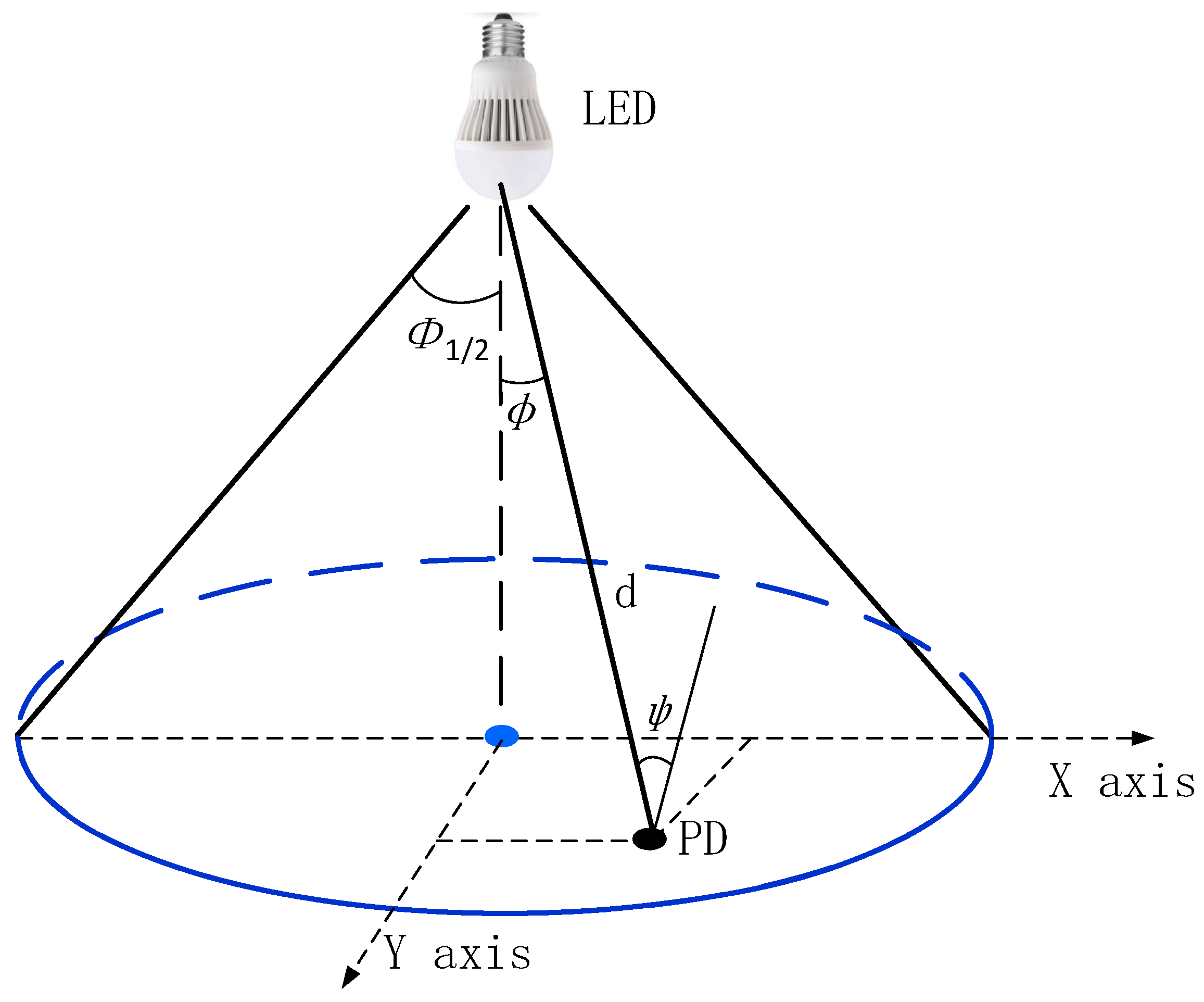
where is the angle of irradiance and is the angle of incidence. is defined as the order of the Lambertian emission with where is the semi-angle at half-power of the LED. denotes the field-of-view (FOV) of the PD. depicts the distance between the color LED chip, and PD. denotes the effective detector area of the PD. Accordingly, the optical channel model is shown in Figure 1.
Based on the analysis of [7], the spectral power distribution (SPD) for the multi-color LED with a peak wavelength and half spectral width is modeled as:
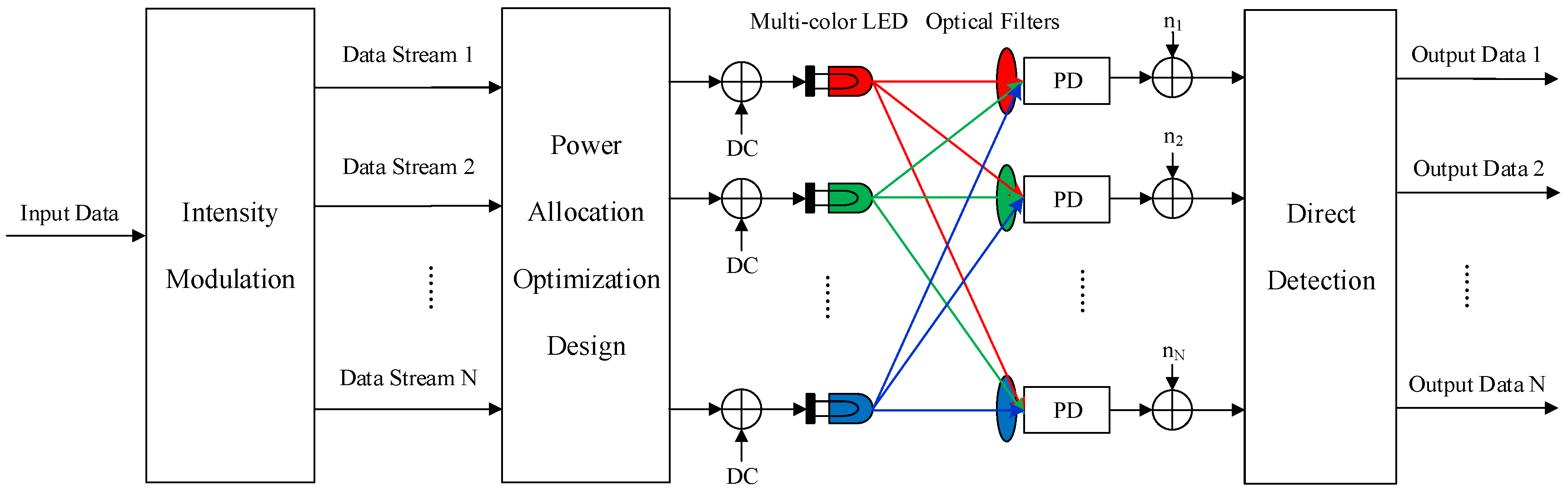
where . The spectral model of a typical red, amber, green, blue LED (RAGB-LED) is shown in Figure 2 at temperature of 300 K, where the optical channel crosstalk will be generated due to the overlapping spectra of the multi-color LED and the imperfection of the optical filters. Obviously, the received optical signal contains the desired signal and interference signal through color filters for the practical multi-color LED-based VLC system. Figure 3 shows the VLC system model considering the channel crosstalk problem, which implies that the conventional WDM-VLC system model is inappropriate. It can be seen that only the two adjacent color bands have the crosstalk problem due to their close wavelength. Thus, the color crosstalk matrix can be described as [17]:
where denotes the crosstalk coefficient. Accordingly, the matrix can be regarded as the identity matrix for the WDM-VLC system model.
At the receiver side, the received signal corrupted by the shot noise and the interference caused by crosstalk can be expressed as:
where denotes the optical/electric (O/E) conversion efficiency of the PD, denotes the channel gain matrix where is a diagonal matrix, and can be modeled as signal-independent additive white Gaussian noise (AWGN) with zero mean and noise variance [18].
With the combination of Equations (1) and (5), the received signal can be rewritten as:
After removing the DC component, the received signal can be rewritten as:
Here, we assume the receiver is interested in the data from the color chip. Accordingly, the received signal from the color LED chip can be expressed as:
3. System Design
As a major source of energy consumption, the lighting energy-saving problem has attracted considerable attention. Therefore, an energy-efficient VLC system should be established. In this section, based on the system model considering the channel crosstalk problem, an optimal power allocation scheme is proposed to maximize energy efficiency via collaboratively satisfying luminance, chromaticity constraints, and SINR requirements.
3.1. Illumination and Communication Constraints
(1) Chromaticity diagram
Chromaticity is the basic characteristic of the color perceived by human eyes. Based on CIE 1931 [19], the XYZcolor system has been established to reference tristimulus value matrix corresponding to the three kinds of cones of the human eyes, which can be modeled as:
where the color matching functions , , and denote the spectral responses of the three kinds of cones. The SPD of the multi-color LED is given by , where denotes the SPD of the color LED chip.
Accordingly, the tristimulus values can be respectively expressed as:
and:
where with for , , and the matrix can be defined as . Thus, we can get the relation between the average transmitted optical power and the tristimulus values as:
The human eye color vision is the projection of onto the plane of in the space, given by as follows [11]:
Based on the above analysis, we define , and we can have the relation between the chromaticity coordinate of mixed color in the CIE 1931 chromaticity diagram and the average transmitted optical power as:
where with .
(2) Quadrangle constraint:
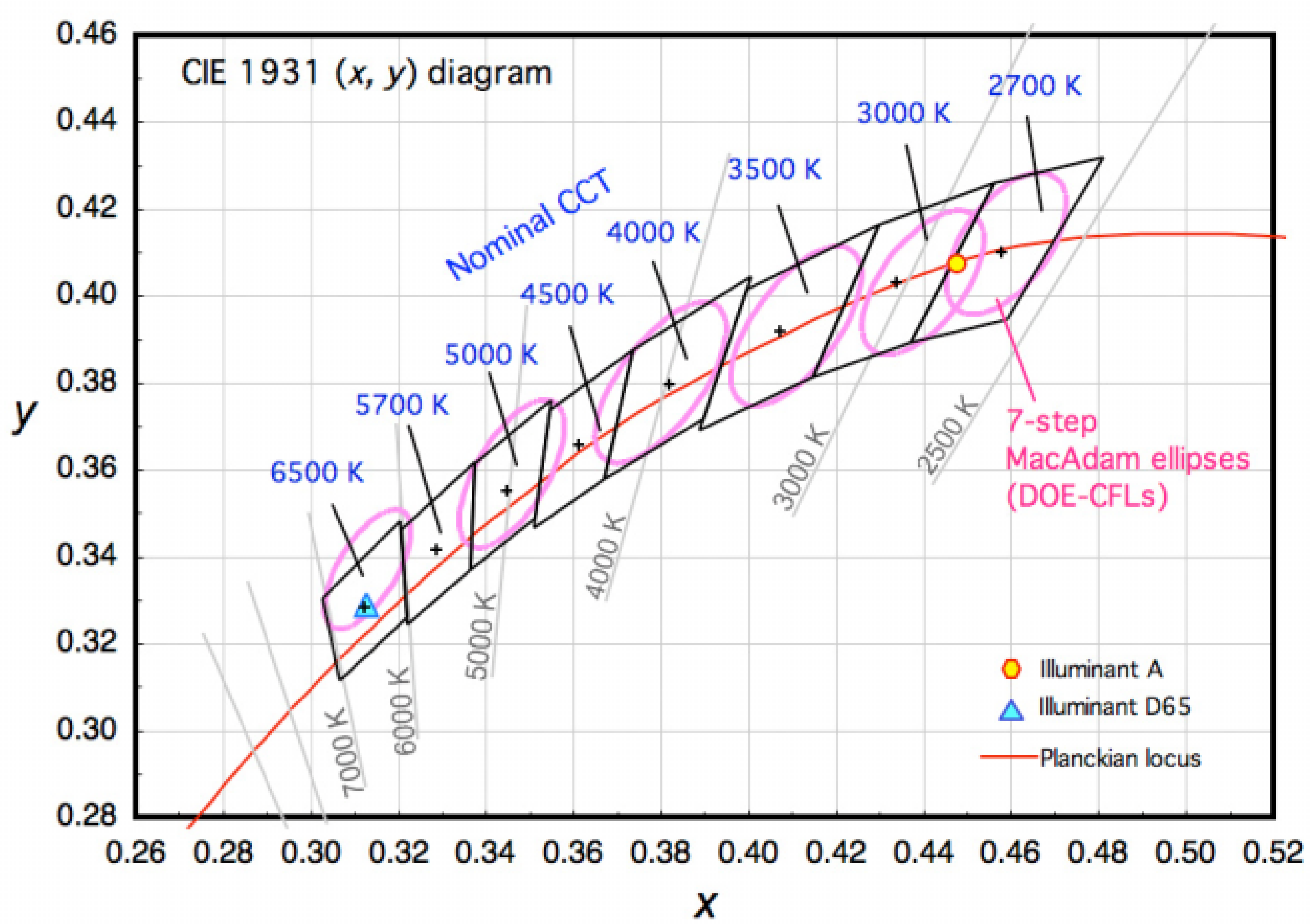
According to the CIE 1931 chromaticity diagram, each coordinate represents a certain chromaticity. It is worth noting that the chromaticity change cannot be perceived in a certain range due to the limitation of human eyes. To specify the range of chromaticity recommended for LED products, ANSI C78.377-2015 [15] has been established to modify the chromaticity tolerances in the quadrangle range instead of a fixed point in the CIE 1931 chromaticity diagram, which provides more degrees of freedom to improve the performance of the system. Table 1 lists the chromaticity coordinates of the center points and the four corners of each quadrangle range constraint for the target white color at different CCTs, which is shown in Figure 4. Therefore, the mixed white light chromaticity constraint in a specific quadrangle range can be expressed as:
where and are the coefficients determined by the quadrangle range in the chromaticity diagram with . In order to make the consistent form, Equation (15) can be rewritten as:
To simplify the expression of the quadrangle constraint (16), we denote:
where and .
(3) Luminance constraint:
Since color matching function is defined as the luminous efficiency function, the tristimulus value Y is roughly correlated with the luminous flux induced by human visual strength, which can be expressed as:
where is the conversion coefficient for the power to luminous flux (P/F). Based on Equation (11), we have the relation between the luminous flux and the average transmitted optical power as:
We define as the minimum luminance requirement, so the luminance constraint can be expressed as:
(4) Transmission power constraint:
Unlike the conventional radio frequency (RF), the minimum value of the instantaneous transmission power should guarantee nonnegativity. As the modulated PAM signal is normalized in the range of , the nonnegative constraint should satisfy:
where and is the minimum level of the transmission power.
Meanwhile, considering the nonlinearity for the LED, the transmitted signal may suffer clipping distortion once the power exceeds the maximum value, so the maximum limitation for the power is necessary. Thus, the maximum transmission power constraint is:
where is the maximum level of the transmission power.
Accordingly, combining Constraints (21) and (22), we can have the transmission power constraint as:
(5) Communication quality constraint:
The VLC technique is the combination of communication and illumination, so the communication quality needs to be satisfied, where SINR is an important factor for improving the overall system performance [20]. Based on Equation (8), the SINR constraint at the receiver can be represented as:
where , and M is the modulation order. To simplify the expression, we let . To satisfy the communication performance, we set the minimum SINR requirement of the th receiver as . Thus, the communication quality constraint can be expressed as:
After the transformation of Equation (25), we have:
For the simple expression, we let where is a nonnegative value, and . Thus, the SINR constraint can be transformed as:
where .
3.2. Problem Formulation
In this subsection, we propose a power allocation optimization design to maximize the energy efficiency under the above-mentioned illumination and communication constraints for the multi-color LED-based VLC system. Thus, the main problem can be formulated as follows:
The optimization problem (28) is determined by three elements, the average transmitted optical power distribution of the multi-color LED , the power amplitude of the modulated optical signal , and the coordinate in the chromaticity diagram . It can be observed that the objective function is the minimum value subject to several linear matrix inequalities, so the optimization problem (28) is convex at each iteration, which can be solved by the interior point algorithm. In this paper, we adopt the CVX toolbox in MATLAB to solve the convex optimization problem [21]. Therefore, the proposed scheme can be summarized as Algorithm 1.
In Algorithm 1, we first create the the initial and randomly satisfying all the constraints, and we set the decision threshold . After an amount of iterations, we can get the minimum transmission power in the loop satisfying the total transmission power . Since the values of initial and are randomly chosen, we would repeat the whole iteration procedure for times to achieve the accurate solution of .
Now, we analyze the complexity of our proposed method in Algorithm 1. The convex optimization would be solved by the CVX toolbox, which has the complexity cost of , where T denotes the inner iteration number of the interior point method [21].
| Algorithm 1: Energy-efficient optimization design. |
| Input: loop times , decision threshold Output: minimum transmission power , While (1) Create the initial , satisfying the constraints (2). Let . Set the iteration number . (2) Solve the convex problem Obj. s.t. (3) Update the value: Until , Update the value: End , |
4. Simulation Results
In this section, simulations are carried out for the practical multi-color based VLC system to testify the performance of our proposed energy-efficient power allocation scheme, where RAGB-LED was employed as the transmitter. The simulation parameters are listed in Table 2. Without loss of generality, the two-level PAM signal with was utilized for transmission.
We first compare the error performance of our proposed system model and the conventional WDM-VLC model ignoring crosstalk under different crosstalk coefficients at CCT K. As shown in Figure 5, compared with the WDM-VLC model, our proposed scheme can improve the error performance and achieve a 0.58-dB SNR gain with crosstalk coefficients at a targeted bit error rate (BER) of , while the SNR gain was 0.98 dB with . Thus, we can conclude that the proposed scheme considering crosstalk can achieve better error performance for the practical VLC system.
As for the influence of the data rate, based on a single and cascaded bridged-T amplitude equalizer, the bandwidth of the multi color chips was about 260 MHz after equalization [10]. After introducing the roll-off factor , the total data rate R can be calculated as:
where B is the bandwidth of the multi-color LED and M is the modulation order of the PAM signal. Therefore, we can conclude that higher-order modulation can achieve high data rate, while it may suffer performance loss caused by the clipping distortion.
Since Ref. [15] has been established to modify the chromaticity tolerances in the quadrangle range to replace a fixed point in the CIE 1931 chromaticity diagram, more degrees of freedom can be achieved to improve the performance of the system. Figure 6 indicates the transmitted optical power of different colors versus the luminance requirement ranging from 10–150 lm. Compared with the fixed chromaticity coordinate constraint, which is regarded as the center point of the target color, the proposed scheme with the quadrangle range chromaticity constraint behaved more energy efficiently, reducing about of the power consumption at most. We can see that the proportion of the optical power distribution for four colors kept relatively constant because of the quadrangle range constraint at low luminous flux. As the luminous flux became larger than 60 lm, the total transmission power increased with the luminance requirement, which implies that the luminance requirement became the main constraint at high luminous flux.
Since the parameters of the quadrangle range changed with the CCT values, the total transmission power under the chromaticity constraint of the quadrangle range is discussed for the different CCT values. As illustrated in Figure 7, the curves had a consistent variation tendency for different CCT values. We can see that better performance can be achieved for CCT = 4500 K at low luminous flux, while smaller CCT values were preferred at a high illumination requirement to reduce power assumption.
To sum up, the recent works still have some drawbacks for the practical multi-color LED-based VLC system. Based on the above-mentioned analysis, compared with the WDM-VLC technique without considering the crosstalk problem, the proposed scheme can maintain better error performance. Moreover, compared with the fixed chromaticity coordinate constraint scheme, the proposed optimal power allocation scheme with the quadrangle range chromaticity constraint can reduce the energy consumption while satisfying the illumination and communication requirements.
5. Conclusions
This paper has considered a multi-color LED-based VLC system where the crosstalk problem among parallel channels is taken into account to increase the practicality. Considering the necessary communication and illumination requirements, we have proposed an optimal power allocation scheme to maximize energy efficiency via collaboratively meeting the luminance, chromaticity, and SINR constraints. Simulation results have indicated that the proposed optimal power allocation scheme can achieve better error performance for considering the channel crosstalk problem. Meanwhile, lower power consumption with the quadrangle range chromaticity constraint can be achieved compared with the fixed chromaticity coordinate constraint.
Author Contributions
All authors contributed equally to writing the paper. Formal analysis, Y.Z.; funding acquisition, J.Z.; writing, original draft, Y.Z.; writing, review and editing, J.Z.
Funding
This work is supported in part by Grant No. 161100210200 from the Major Scientific and Technological fundof Henan Province, China.
Acknowledgments
The authors wish to thank the anonymous reviewers for their valuable suggestions.
Conflicts of Interest
The authors declare no conflict of interest.
References
- Komine, T.; Nakagawa, M. Fundamental analysis for visible light communication system using LED lights. IEEE Trans. Consum. Electron. 2004, 50, 100–107. [Google Scholar] [CrossRef]
- Kavehrad, M. Sustainable energy-efficient wireless applications using light. IEEE Commun. Mag. 2010, 48, 66–73. [Google Scholar] [CrossRef]
- Elgala, H.; Mesleh, R.; Haas, H. Indoor optical wireless communication: Potential and state-of-the-art. IEEE Commun. Mag. 2011, 49, 56–62. [Google Scholar] [CrossRef]
- Jovicic, A.; Li, J.; Richardson, T. Visible light communication: Opportunities, challenges and the path to market. IEEE Commun. Mag. 2013, 51, 26–32. [Google Scholar] [CrossRef]
- Grobe, L.; Paraskevopoulos, A.; Hilt, J.; Schulz, D.; Lassak, F.; Hartlieb, F.; Kottke, C.; Jungnickel, V.; Langer, K.D. High-speed visible light com- munication systems. IEEE Commun. Mag. 2013, 51, 60–66. [Google Scholar] [CrossRef]
- Steigerwald, D.A.; Bhat, J.C.; Collins, D.; Fletcher, R.M.; Holcomb, M.O.; Ludowise, M.J.; Martin, P.S.; Rudaz, S.L. llumination with solid state lighting technology. IEEE J. Sel. Top. Quant. 2002, 51, 310–320. [Google Scholar] [CrossRef]
- Ohno, Y. Spectral design considerations for white LED color rendering. Opt. Eng. 2005, 44, 333302-1–111302-9. [Google Scholar] [CrossRef]
- Dong, J.; Zhang, Y.; Zhu, Y. Convex relaxation for illumination control of multi-color multiple-input-multiple- output visible light communications with linear minimum mean square error detection. OSA Appl. Opt. 2017, 56, 6587–6595. [Google Scholar] [CrossRef] [PubMed]
- Wang, Y.; Huang, X.; Tao, L.; Shi, J.; Chi, N. 4.5-Gb/s RGB-LED based WDM visible light communication system employing CAP modulation and RLS based adaptive equalization. Opt. Express. 2015, 23, 13626–13633. [Google Scholar] [CrossRef] [PubMed]
- Wang, Y.; Tao, L.; Huang, X.; Shi, J.; Chi, N. 8-Gb/s RGBY LED-based WDM VLC system employing high-order CAP modulation and hybrid post equalizer. IEEE Photonics J. 2017, 7, 1–7. [Google Scholar] [CrossRef]
- Gong, C.; Li, S.; Gao, Q.; Xu, Z. Power and rate optimization for visible light communication system with lighting constraints. IEEE Trans. Signal Process. 2015, 63, 4245–4256. [Google Scholar] [CrossRef]
- Gao, Q.; Wang, R.; Xu, Z.; Hua, Y. DC-informative joint color-frequency modulation for visible light communications. J. Lightware Technol. 2015, 33, 2181–2188. [Google Scholar] [CrossRef]
- Jiang, R.; Wang, Z.; Wang, Q.; Dai, L. Multi-User Sum-Rate Optimization for Visible Light Communications with Lighting Constraints. J. Lightware Technol. 2016, 34, 3943–3952. [Google Scholar] [CrossRef]
- Cui, L.; Tang, Y.; Jia, H.; Luo, J.; Gnade, B. Analysis of the multichannel WDM-VLC communication system. J. Lightware Technol. 2016, 34, 5627–5634. [Google Scholar] [CrossRef]
- ANSI C78.377-2015: Electric Lamps Specifications for the Chromaticity of Solid-state Lighting Products; American National Standard Institute: Washington, DC, USA, 2015.
- Zeng, L.; O’Brien, D.C.; Minh, H.L.; Faulkner, G.E.; Lee, K.; Jung, D.; Oh, Y.J.; Won, E.T. High data rate multiple input multiple output (MIMO) optical wireless communications using white LED lighting. IEEE J. Sel. Area Commun. 2009, 27, 1654–1662. [Google Scholar] [CrossRef]
- Gao, Q.; Gong, C.; Xu, Z. Joint transceiver and offset design for visible light communications with input-dependent shot noise. IEEE Trans. Wire Commun. 2009, 27, 1654–1662. [Google Scholar] [CrossRef]
- Moser, S.M. Capacity results of an optical intensity channel with input-dependent gaussian noise. IEEE Trans. Inf. Theory 2012, 58, 207–223. [Google Scholar] [CrossRef]
- Kriss, M.A. Colorimetry: Fundamentals and Applications; John Wiley & Sons: Hoboken, NJ, USA, 2006. [Google Scholar]
- Wiesel, A.; Eldar, Y.C.; Shamai, S. Linear precoding via conic optimization for fixed MIMO receivers. IEEE Trans. Signal Process. 2005, 54, 161–176. [Google Scholar] [CrossRef]
- Grant, M. CVX: Matlab Software for Disciplined Convex Programming, version 1.21. 2008; 155–210.
Figure 1.
Optical channel model.

Figure 2.
Emission spectra of LEDs with different colors.

Figure 3.
The model of the multi-color-based VLC system.

Figure 4.
The chromaticity tolerance with the quadrangle range for LED products on the CIE 1931 chromaticity diagram.
Figure 4.
The chromaticity tolerance with the quadrangle range for LED products on the CIE 1931 chromaticity diagram.

Figure 5.
Error performance for the proposed system model and the conventional wavelength-division multiplexing (WDM)-VLC model under different crosstalk coefficients at CCT = 5000 K.
Figure 5.
Error performance for the proposed system model and the conventional wavelength-division multiplexing (WDM)-VLC model under different crosstalk coefficients at CCT = 5000 K.

Figure 6.
Transmission power of the proposed scheme with quadrangle range chromaticity tolerance and a fixed chromaticity point at crosstalk coefficients and CCT = 3000 K.
Figure 6.
Transmission power of the proposed scheme with quadrangle range chromaticity tolerance and a fixed chromaticity point at crosstalk coefficients and CCT = 3000 K.

Figure 7.
Total transmission power for different CCT values at crosstalk coefficients .


Table 1.
Coordinate of the four corners for the quadrangle constraint at different correlated color temperatures (CCTs).
Table 1.
Coordinate of the four corners for the quadrangle constraint at different correlated color temperatures (CCTs).
| CCT | Center Point | (x,y) Tolerance Quadrangle | |||
|---|---|---|---|---|---|
| A | B | C | D | ||
| 3000 K | (0.4339,0.4033) | (0.4562,0.4260) | (0.4303,0.4173) | (0.4150,0.3821) | (0.4373,0.3893) |
| 3500 K | (0.4078,0.3930) | (0.4303,0.4173) | (0.4003,0.4035) | (0.3895,0.3709) | (0.4150,0.3821) |
| 4000 K | (0.3818,0.3797) | (0.4003,0.4035) | (0.3737,0.3880) | (0.3671,0.3583) | (0.3895,0.3709) |
| 4500 K | (0.3613,0.3670) | (0.3737,0.3882) | (0.3550,0.3754) | (0.3514,0.3482) | (0.3672,0.3585) |
| 5000 K | (0.3446,0.3551) | (0.3550,0.3753) | (0.3375,0.3619) | (0.3366,0.3373) | (0.3514,0.3481) |
Table 2.
Simulation parameters utilized in the RAGB LED VLC system. O/E, optical/electric; P/F, power to luminous flux.
Table 2.
Simulation parameters utilized in the RAGB LED VLC system. O/E, optical/electric; P/F, power to luminous flux.
| Parameters | Values |
|---|---|
| Type of multi-color LED | RAGB LED |
| Room size | 5 m × 5 m × 3 m |
| LED height | 2.5 m |
| Table height | 0.85 m |
| FOV | |
| Half power angle of LED | |
| Irradiance angle | |
| Incidence angle | |
| Effective detector area of PD | 1 cm |
| O/E conversion efficiency | 0.5 A/W |
| P/F conversion efficiency | 20 lm/W |
| minimum transmission power | 1 W |
| maximum transmission power | 10 W |
| SINR requirement | 10 dB |
| Noise variance | W |
| R 664 nm | |
| A 594 nm | |
| Peak wavelength of each color | G 538 nm |
| B 465 nm |
© 2018 by the authors. Licensee MDPI, Basel, Switzerland. This article is an open access article distributed under the terms and conditions of the Creative Commons Attribution (CC BY) license (http://creativecommons.org/licenses/by/4.0/).
Share and Cite
MDPI and ACS Style
Zuo, Y.; Zhang, J. Energy-Efficient Optimization Design for the Multi-Color LED Based Visible Light Communication Systems under Illumination Constraints. Appl. Sci. 2019, 9, 1. https://doi.org/10.3390/app9010001
AMA Style
Zuo Y, Zhang J. Energy-Efficient Optimization Design for the Multi-Color LED Based Visible Light Communication Systems under Illumination Constraints. Applied Sciences. 2019; 9(1):1. https://doi.org/10.3390/app9010001
Chicago/Turabian StyleZuo, Yu, and Jian Zhang. 2019. "Energy-Efficient Optimization Design for the Multi-Color LED Based Visible Light Communication Systems under Illumination Constraints" Applied Sciences 9, no. 1: 1. https://doi.org/10.3390/app9010001
Note that from the first issue of 2016, this journal uses article numbers instead of page numbers. See further details here.