Enhancing the Viscoelastic Performance of Carbon Fiber Composites by Incorporating CNTs and ZnO Nanofillers


Department of Aerospace Engineering, Embry-Riddle Aeronautical University, Daytona Beach, FL 32114, USA
*
Author to whom correspondence should be addressed.
Appl. Sci. 2019, 9(11), 2281; https://doi.org/10.3390/app9112281
Submission received: 26 April 2019
/
Revised: 23 May 2019
/
Accepted: 27 May 2019
/
Published: 3 June 2019
(This article belongs to the Special Issue Nanocharacterization and Innovation at Nanoscale)
Abstract
:Carbon fiber reinforced plastic composites (CFRPs) possess superior elastic mechanical properties. However, CFRPs lack sufficient viscoelastic performance, such as damping and creep resistance. In an effort to improve these properties, in this study, hybrid multiscale composites with various combinations of zinc oxide nanorods (ZnO) and carbon nanotubes (CNTs) were deposited at the interface of carbon fiber laminae. The viscoelastic properties of the corresponding composites were characterized via dynamic mechanical analysis (DMA) during both temperature and frequency sweeps. The creep activation energy for each composite configuration was also calculated. The DMA temperature sweep analysis reported that the composite incorporating both ZnO and CNTs exhibited the highest improvements in all viscoelastic properties. This composite also attained better creep resistance, evident by the highest activation energy. The DMA frequency sweep analysis revealed that composites incorporating a single nanofiller improves the viscoelastic properties more than the combined nanofiller composite. Despite these improvements in the viscoelastic properties, the non-uniform dispersion and agglomerations of the nanofillers affected some of the elastic properties negatively, such as the storage modulus.
1. Introduction
Carbon fiber reinforced plastic composites (CFRPs) have manifested their superior strength and stiffness capabilities in various industries, such as aerospace, civil infrastructure, and marine and automotive transportations [1,2]. Most of these applications expose the CFRPs to loading and operating conditions that may induce vibrational oscillations. These motions are usually prominent around the natural frequencies of the system and often lead to structural damage and failure, and as such, cannot be ignored. Practically, the vibration attenuation can be carried out either passively or actively. Passive techniques use the intrinsic ability of certain materials to absorb the vibration energy (for example, via mechanical deformation in viscoelastic materials). Active methods employ sensors to attain the vibrations and actuators to suppress them in real time. Typically, these sensors and actuators are made of piezoelectric materials [3]. For fiber-reinforced composites (FRPs), vibration damping is achieved by embedding a viscoelastic matrix [4]. However, the mere addition of viscoelastic polymer lowers the strength and the modulus of the structure (per the rule of mixtures). Alternatively, in the stiffer phase, the fibers, can be tailored such that they contribute to vibration attenuation. Several approaches have been carried out to improve the fibers’ damping capabilities, including fiber surface chemical functionalization, interlaminar interface improvement by adding metal particles, surface polymerization [5], adding carbon nanofibers [6], and viscoelastic polymer particles [7].
The discovery of carbon nanotubes (CNTs) in the late 1990s has invoked the idea of utilizing nano-additives to improve the interlaminar shear stress (ILSS) of CFRPs [8]. These allotropes of carbon possess exceptionally high aspect ratios, along with high thermal and electrical conductance [9,10,11,12]. They can be grown on various substrates, including silicon and alumina [13,14]. Despite their superior mechanical and transport properties, CNTs are prone to the problems associated with agglomeration [15,16,17,18]. When dispersed in viscous media, they tend to form huge entangled colonies in random locations. Nisrin et al. [19] studied this effect at the macro scale by fabricating two layer composites with different concentrations of CNTs. In addition to CNTs)-enriched matrix, a CNT-rich sizing agent was also applied to the carbon fabric prior to the land layup vacuum bagging process used to make the composites. The results of tensile tests and fracture analysis revealed deterioration in the mechanical properties beyond certain concentrations of CNTs due to agglomeration [5,20]. To mitigate agglomeration, several studies suggested functionalization of CNTs with various carboxyl, nitrile, or fluoride groups prior to their dispersion in any matrix [21]. These chemical groups allow CNTs to act hydrophobically, thus, improving their field emission characteristics and allowing fine-tuning of their electro chemical properties.
Suhr et al. [22] conducted direct shear testing of epoxy thin films containing multi-walled carbon nanotubes (MWCNTs) and reported strong viscoelastic behavior with a 1400% increase in loss factor (damping ratio) over the baseline epoxy. Koratkar et al. [23] employed MWCNT thin films as interlayers to reinforce the interfaces between composite plies, enhancing laminate stiffness and structural damping. The flat-wise bending tests of a piezosilica composite beam with an embedded nano-film sublayer indicated up to 200% increase in the damping level and 30% increase in the baseline bending stiffness. In this research, the CNTs were densely packed on a silicon substrate before being coated with epoxy. This treatment would bring significant damping, but fabrication could be costly and difficult. In addition, the weight % of CNTs is high in this case, which may not be economical. Zhou et al. [24] fabricated composites with randomly dispersed single-walled carbon nanotube (SWCNT) addition. Analytical results showed strain-dependent damping enhancement due to stick-slip motion at the interfaces of the SWCNTs and the resin.
Other nanofillers utilized for vibration damping are zinc oxide (ZnO) nanowires. With a wurtzite structure, these nanowires possess excellent pyroelectric and piezoelectric properties, besides being semiconductors [25,26]. They also take various morphologies, such as nanorings, nanocombs, nanobelts, nanorods, nanosprings, and nanocages [27]. Methods to grow them on various substrates include CVD, electrodeposition, and hydrothermal growth [28,29,30,31,32,33]. Most of these methods require deposition of a self-seeding layer on the substrate before growth initiation. Also, the growth temperatures are high for some of these procedures, such as the case of chemical vapor deposition (CVD). Thus, hydrothermal routes are ideal for carbon fiber substrates. In this procedure, growth is carried out in the presence of zinc salts, such as zinc nitrate hexahydrate, zinc acetate, zinc chloride, or zinc acetate dehydrate [34,35,36,37,38,39]. It was also shown that hexamethylenetetramine (HMTA) plays a dual role of pH regulation and forcing the vertical growth of zinc nanorods along the c-axis by inhibiting any lateral growth [40]. It has been reported by Skandani et al. [41] that nanorods at the interface of CFRPs enhance loss modulus by 50%, thus improving the damping properties of the composite.
When damping properties are collected in abundance during dynamic mechanical analysis (DMA), these data can be utilized to predict the thermal activation energy, and thus, the creep behavior of the material. Goertzen et al. [42] examined the operating temperatures of the CFRPs used in structural pipe repair using this procedure. Industrial grade CFRPs were fabricated and cured at a temperature range between 35 and 170 °C. Calculation of the glass transition temperature, Tg, and variation under different curing and vibration conditions helped estimate safe operating temperatures for the CFRP materials during pipe maintenance. The glass transition temperature represents the threshold for deterioration of material properties, such as fracture toughness, strength, and stiffness. It was concluded that the material should be cured at higher temperatures to increase the Tg for servicing at higher temperatures. Li et al. [43] described the procedures to determine thermal activation energy of an epoxy from the Tg values obtained from the DMA results. They concluded that the data based on loss tangent was more reliable compared to the data from loss modulus for the calculation of thermal activation energy at lower frequencies. The activation energy values increased at higher frequencies. The importance of constant heating rates to systematically compensate the error resulting from the measured sample temperatures was discussed by Flynn [44]. Theoretical insight into the Arrhenius equation used for the calculation of thermal activation energy was provided in this paper. This equation, along with Gibb’s free energy approach, are frequently used to model creep [45]. Thermal activation energy is an essential parameter necessary to determine creep in all these models. Thus, determination of this parameter is crucial for modeling creep behavior in the new hierarchical composites [46].
This investigation focuses on revealing the changes in the dynamic mechanical properties and activation energy of a woven CFRP as consequences of adding CNTs and ZnO nanofillers, individually or combined, at the interface of The CFRPs. In our previous work [47], the addition of Bucky paper and ZnO nanorods was studied. The planar orientation of CNTs in Bucky paper resulted in a weak adhesion to the epoxy matrix at the interface. Thus, in the current study a different technique to deposit CNTs is adopted. In addition to the damping properties, the activation energy of each configuration of composites is estimated.
2. Synthesis
Un-sized plain-woven carbon fiber fabric (IM7-GP, 6K filaments count in a tow), provided by Hexcel Inc. (Stamford, CT, USA), was used as the primary reinforcement material. The MWCNTs from Cheap Tubes Inc. (Cambridgeport, VT, USA), with an approximate purity > 95 wt %, were used in the following experiments. They have a length range of 10–50 μm, outer diameter 20–30 nm, and inner diameter 5–10 nm.
2.1. Nanofillers Deposition
The ZnO nanorod synthesis essentially requires two procedures: seeding, and growth for them to bond to the carbon fabric substrate. Dip-coating method was employed for seeding purposes. A seeding solution was prepared with 658.4 mg of zinc acetate dehydrate (Alfa Aesar, Tewksbury, MA, USA), 600 mL of deionized (DI) water, and 80 mL of ethanol, sonicated together for 10 min. The carbon fiber substrate was dipped in this solution for five iterative cycles. Each cycle includes dipping, drying, and rinsing with ethanol. The substrate was further dried at 100 °C for 30 min after the completion of the seeding procedure.
The growth procedure involves preparing a bath of DI water, in which zinc acetate dehydrate and hexamethylenetetramine (HMTA, Alfa Aesar, Tewksbury, MA, USA) were added in adequate amounts. A homogenized mixture of zinc acetate dehydrate (15.72 g) and HMTA (10.09 g) with DI water (3600 mL) was achieved via sonication. Based on a parametric study for the time and temperature dependence of the length and diameter of nanorods, 90 °C and 8 h growth time was chosen for this experiment.
The carbon fiber fabrics with surface-grown ZnO nanorods were dried further in preparation of the deposition of CNTs. Air brush spraying technique was employed for this process. Ethanol was utilized as a solvent, while cyclohexyl-2-pyrrolidone was used a surfactant. The multiwalled CNTs (1.5% wt.) were sonicated for 30 min with ethanol to cyclohexyl-2-pyrrolidone (CHP) ratio of 80 to 20 volume%. This final suspension was sprayed over the carbon fiber substrate five times, with appropriate drying time between each iteration.
With hydrothermal and spraying techniques to grow nanorods and nanotubes, respectively, the growth is randomly scattered over the carbon fabric, as seen in Figure 1. However, the adhesion to the fabric is ensured by drying the samples for 24 h at 90 °C before making the composite. Tensile tests and fracture analysis performed for various configurations by the authors previously [48] clearly indicated an increase in the interfacial shear strength due to the addition of nanofillers.
2.2. Composites Preparation
After the growth of the designated nanofillers on the carbon fiber substrate, four configurations of three-ply composites with different treatments of the carbon fibers were fabricated, namely, carbon fiber as is (CF as is), carbon fiber with ZnO growth (CF and ZnO), carbon fiber with sprayed CNTs (CF and CNTs), and carbon fiber with both ZnO and CNTs nanofillers (CNTs and ZnO). The epoxy used was Aeropoxy TM (PTM&W Industries, Inc.; Santa Fe Springs, CA, USA). This epoxy is comprised of two components: PR2032, a Bisphenol-based resin, and PH3660, a hardener. The resin possesses medium viscosity (1650 cPs at room temperature) and is designed especially for structural production applications. It is known for smooth lamination and readily wets out fiberglass, carbon, and aramid fibers. The hardener is relatively of low viscosity (190–200 cPs at room temperature). On mixing them together in the ratio of 100:27 by weight, a viscosity of 800–875 cPs and a glass transition temperature of 91 °C are expected. This epoxy system was utilized by multiple authors to manufacture CFRPs [48,49] and nanocomposites based on SWCNTs [50], MWCNTs [16], and Bucky paper [47]. The fabrics interleaved with nanofillers were impregnated with the epoxy following the hand layup procedures. This lay-up was placed in a vacuum bag connected to a vacuum pump. A composite press (Wabash MPI, Wabash, IN, USA) was used to compress the contents of the bag at a pressure of 1.5 tons-force while curing the epoxy at 60 °C for two hours. These composites are further cured for 24 h at room temperature.
3. DMA Analysis and Thermal Activation Energy Calculation
Dynamic mechanical analysis (DMA 8000, PerkinElmer, OH, USA) allows temperature and frequency sweeps to measure dynamic viscoelastic properties at constant frequency and temperature, respectively. It gives the storage modulus, which is proportional to the energy stored, the loss modulus, which is proportional to the energy dissipated, and the ratio of loss modulus to storage modulus is defined as , which is a measure of the damping capacity of the material. The DMA 8000 allows temperature scanning up to 400 °C and frequency range up to 600 Hz ± 0.001 Hz. The force and displacement ranges are ±10 N and ±1000 μm with resolutions 0.002 N and 1 nm, respectively. The resolutions of the measured moduli are 0.0001 Pa, and for tan delta the resolution is 0.00001.
Besides the viscoelastic and damping properties, the DMA can also identify the glass transition temperature, Tg. Typically, differential scanning calorimetry (DSC) is used to measure Tg. However, according to the ASTM D4065 standard [51], the peak of loss modulus vs. temperature curve can be considered as an alternative to identify Tg for practical purposes. The tan delta vs. temperature peak can also be used for the same purpose. However, there is usually a discrepancy in the data when the comparison is made between both results. Thus, an error margin of around 25 °C is usually expected when deciding the Tg [42].
While samples can be mounted using various fixtures, three-point bending fixture was utilized in this study, as it can eliminate errors resulting from clamping the sample. A maximum displacement of 0.05 mm was used for all experiments. For the temperature scan, a temperature range from 30 °C to 170 °C was considered to provide a reliable fit to the Arrhenius equation used for the calculation of thermal activation energy. In the most basic form, this equation is given by:
where is the rate constant, is the pre-exponential factor, is the activation energy, is the gas constant and is the absolute temperature [44]. For viscoelastic analysis, this equation is modified to calculate activation enthalpy, , by the time-temperature superposition principle. The or loss modulus peaks at different frequencies are superimposed on a logarithmic time axis, where they are shifted by a factor of [43]. Thus, the original equation is modified as:
where and are analogous to and , respectively. Due to the change in frequency, is calculated as follows:
Applying logarithmic of either sides of the above equation,
where . The final equation for can be rearranging the terms in the above equation as:
This equation infers that the slope of the curve vs. gives for polymers using dynamic mechanical analysis. To reduce errors due to increasing temperature in this equation, constant heating rates of 2 °C min−1 were used [44].
To compare the damping characteristics of the different composites’ configurations, temperature and frequency sweeps were performed for each configuration. The dimensions of the samples were in the range of 2.0 in × 0.20 in × 0.024 in. For the temperature sweep, a constant frequency of 1 Hz, temperature range of 30 to 170 °C, constant heating rate of 2 °C min−1, and a maximum displacement of 0.05 mm were chosen as experimental parameters. For the frequency sweep, a constant temperature of 30 °C, frequency range of 1 to 100 Hz, and maximum displacement of 0.05 mm were chosen as experimental parameters. This was followed by temperature sweeps of all four configurations at four different constant frequencies: 1 Hz, 3.16 Hz, 10 Hz, and 100 Hz. Additionally, ln(f) vs. 1/Tg graphs were plotted to calculate for each configuration by both loss modulus and tan delta Tg peaks.
4. Results and Discussion
4.1. Temperature Sweep
The viscoelastic properties for the different composites’ configurations from the temperature sweep at a frequency of 1 Hz are plotted in Figure 2. As mentioned earlier, the glass transition temperature, Tg, can be found from either the first inflection point of the storage modulus curve or the peak of loss modulus, or the peak of the curve. During glass transition, the polymer molecular segments absorb heating energy and begin to move. However, the presence of the nanofillers diminishes the available space that would allow the molecular movement, thus more energy (and higher temperature) is needed to go around these hurdles.
As seen in Table 1, there are significant differences between the Tg values calculated from , vis-a-vis those calculated from the loss modulus peaks. When the tanδ curves were considered, the composite configuration with both CNTs and ZnO achieved the highest value for Tg at 82 °C. A similar trend was not observed from the loss modulus curves. The configuration with raw carbon fibers is seen to have the highest value of Tg at 73.3 °C.
As seen in Table 2, the addition of nano-fillers significantly improves the values. The highest increase of 11% was observed when both CNTs and ZnO were deposited at the interface of the carbon fabrics layers. This can be clearly seen in Figure 2a. This trend was not observed when only CNTs were added to the interface, which could be attributed to poor dispersion of CNTs in the sample, as seen in the SEM micrograph of Figure 1c. This agglomeration can result in early delamination or poor mechanical characteristics. This might also be a consequence of CHP utilized for the dispersion of CNTs [52]. There is a possibility these groups form bonds with epoxy and effect the cross-linking of resin with the fiber.
In the presence of ZnO and CNTs, both loss and storage moduli show a significant improvement of 16% and 26%, respectively, as shown in Table 2. These trends are shown in Figure 2b,c. This implies that the composite exhibits improvement in both viscous and elastic properties. This trend was not observed for composites comprising individual fillers where they exhibited considerable drop in both moduli. This can be attributed to the diminishing space for molecular movements due to the high density of nanofillers in the sample that has both nanofillers. The composites with individual fillers demand a uniform distribution of nanorods or nanotubes to show improvement in this aspect. The values for comparison of storage modulus from Figure 2c are taken at 60 °C (below the glass transition temperature). As the storage moduli curve transitions from glassy state to the rubbery plateau state, the differences in values for various configurations become negligible.
4.2. Frequency Sweep
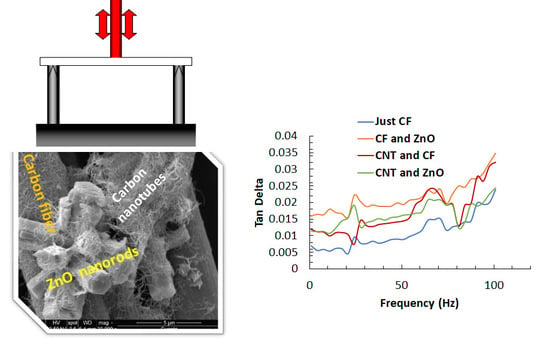
As seen in Figure 3a,b, the and the loss moduli followed similar trends as the frequency increases from 1 Hz to 100 Hz. In general, the values increased with increasing frequency. Peaks were seen around 25 Hz, 70 Hz, and 100 Hz for all the configurations. The was improved from values ranging 45–85% for various nanofillers additions when compared to the raw carbon fiber sample, as shown in Table 3. The loss modulus values showed an increase of values ranging 32–70%. This implies enhanced damping due to the increase in interfacial surface area resulting from high aspect ratios of CNTs and ZnO nanorods. The ZnO nanorods were reported to exhibit enhanced damping capabilities in the presence of a polymer due to dissipation by friction between the matrix and ZnO, and due to the electromechanical coupling [41]. The numbers also indicate that at higher frequencies, the addition of just one nanofiller is more advantageous than adding both ZnO and CNTs for better dissipation capabilities.
Figure 3c shows that the storage moduli are almost independent of frequency for all the configurations. However, there is a negative peak at around 70 Hz. This peak indicates these composites might see a degradation in performance when operated at this frequency. Also, there is a significant decrease in the values of storage moduli for the composites with nanofillers when compared to the raw fiber composite, as seen in Table 3 and Figure 3c. This might be due to their exposure to high moisture levels during the hydrothermal growth of ZnO nanorods and the agglomeration during spraying of CNTs.
4.3. Effect of Frequency on Glass Transition Temperature
For the calculation of activation energy, Tg values at different frequencies are necessary. In general, as the frequency increases, Tg increases. This trend is signified by the right-biased shift of the plots in Figure 4a,b. The shifts in Tg range from 16–28 °C when the frequency is varied between 1 Hz to100 Hz, as seen in Figure 4a. The value of peak also slightly increases at higher frequencies. Similarly, Tg differences ranging from 10–20 °C are noted in loss modulus curves shown in Figure 4b. The peak values of loss modulus also slightly increase with an increase in frequency.
As seen in Figure 4c, the storage modulus values tend to increase with frequency. At 100 Hz, the values are much higher than those at lower frequencies. Also, significant noise was observed in the data after passing the corresponding glass transition temperature at this frequency. However, these trends hold for this configuration, where just CNTs are embedded as nanofillers. For other configurations, though the Tg increases with frequencies, fluctuations were noticed in the peaks of tan delta and loss modulus curves. The storage modulus values after the rubbery plateau, which is around 100 °C, are largely independent of temperature and frequency changes. The slight shift of the storage modulus curves to the left as the frequency increases indicates that the glass transition depends on the frequency, as reported before [53]. Glassy to rubbery transitions shift to higher temperatures at higher frequencies. The shift to higher temperatures is a direct consequence of time–temperature equivalence. As the frequency is increased, the time allowed for molecular motion is decreased, increasing the possibility of shorter timescale motions. Hence, the polymer responds more as if it were at a lower temperature than a sample run at a lower frequency but the same temperature. Consequently, higher temperatures are required for a sample to achieve an equivalent mechanical state at higher frequencies, and the transitions shift to higher temperatures.
4.4. Calculation of Thermal Activation Energy (ΔH)
From the analysis discussed in Section 3, the slope of ln(f) vs. 1/Tg curve gives the value of . The Tg values were obtained by the peaks of the loss modulus and the peaks of the tan delta curves at different frequencies for each configuration. From the variation of the Tg from the storage modulus or tan delta curves as a function of the frequency, transition maps can be compiled using Equation (5). Since the locus of the transition maps are straight lines, as seen in Figure 5, an activation energy for the phenomena responsible for the viscoelastic behavior can be estimated.
As shown in Figure 5, linear approximation was used to estimate the slope of the curves for all configurations. Equation (5) was used to calculate for each sample using both methods. These results are displayed in Table 4, where values for vary from 0.83–0.96 kJ/mol. In general, the samples with nanofillers seem to show an improvement in when compared to raw composite sample. The highest value of was seen in the samples that have just CNTs as nanofillers, reporting a value of 0.96 kJ/mol. The difference between both the methods is not profound, as seen in Table 4. The creep rate is related to the thermal activation energy (i.e.; change in activation enthalpy) by the following relation:
where is the Arrhenius constant, is the applied stress, is the stress is the activation enthalpy (also known as activation energy), R is the gas constant, and is the absolute temperature [46]. This equation implies that the creep rate is exponentially and inversely related to the activation energy. Hence, as seen in Table 4, the improvement in the activation energy significantly decreases the creep rate of the hierarchical composites. For example, assuming all the parameters are the same in Equation (6) and varying from 0.85 for CF sample to 0.96 for the CF and CNTs sample will drop the creep strain rate by 20%.
5. Conclusions
Four different configurations of triple ply composites were prepared and characterized for their damping properties. Temperature analysis showed about 11%, 16%, and 26% improvement in tan delta, loss modulus, and storage modulus, respectively, when both CNTs and ZnO nanorods co-exist in the composite. An evident trend for Tg variation cannot be seen when various nanofillers were added. However, it can be concluded that all the configurations have a Tg between 70–83 °C. Also, a significant variation in Tg of 11% between loss modulus and tan delta peaks was noted. The anticipated trend was to see an increase in glass transition when adding a nanofiller, as the nanofiller will increase the resistance of the chain movement. However, as several other articles stated, the bundling effect of CNTs often led to a decrease in the Tg of an epoxy. Allaoui and Bounia [54] surveyed the results of 15 different investigations and have shown that that there is no clear trend to how MWCNTs affect the Tg, and they attributed these inconclusive results to agglomeration, use of different solvents or dispersants in CNTs, and deviation in the degree of curing.
Frequency analysis indicated that the addition of a single nanofiller is more advantageous when operated above 60 Hz. Tan delta improved from 48–85% with the addition of various nanofillers, while loss modulus improved from 30–70% due to the additives. There is a significant drop in storage modulus due to the absorbed moisture during the growth step.
Also, the effect of frequency on the various damping variables was investigated. In general, all three viscoelastic parameters tend to increase with higher frequency. The value for Tg also shifts towards the right side of the graphs as frequency increases. These values were used to calculate the slope of existing linear relation between the frequency and Tg. This was followed by the calculation of for all four configurations. No significant variations were seen between loss modulus and tan modulus results. The values for increased due to the addition of nanofillers, the highest being the composite with CNTs as nanofillers. This study provides proof that ZnO and CNTs as interfacial nanofillers are essential for enhancing the damping properties and decreasing the creep rate in CFRPs. However, efforts are being made for more uniform patterns of these nanofillers on carbon fabric. This can help in establishing more profound trends in changes with the addition of nanofillers.
Author Contributions
S.A. carried out the growth of ZnO nanorods and deposition of CNTs, manufacturing, and DMA characterization of the hybrid composites. M.A.-H. guided this research, developed the technique for growth of ZnO on carbon fibers, and assisted in manufacturing and characterization of the hybrid composites.
Funding
This research received no external funding.
Acknowledgments
M.A.-H. gratefully acknowledges the support from Embry-Riddle Aeronautical University Accelerated Research Imitative (ARI) grant.
Conflicts of Interest
The authors declare no conflict of interest.
References
- Siochi, E.J.; Harrison, J.S. Structural nanocomposites for aerospace applications. MRS Bull. 2015, 40, 829–835. [Google Scholar] [CrossRef] [Green Version]
- Fitzer, E. Technical Status and Future Prospects of Carbon Fibres and their Application in Composites with Polymer Matrix (CFRPs); Springe: Berlin, Germany, 1985; pp. 3–45. [Google Scholar]
- Raja, S.; Prathap, G.; Sinha, P.K. Active vibration control of composite sandwich beams with piezoelectric extension-bending and shear actuators. Smart Mater. Struct. 2002, 11, 63–71. [Google Scholar] [CrossRef]
- Gibson, R.F.; Chen, Y.; Zhao, H. Improvement of Vibration Damping Capacity and Fracture Toughness in Composite Laminates by the Use of Polymeric Interleaves. J. Eng. Mater. Technol. 2001, 123, 309–314. [Google Scholar] [CrossRef]
- Kuttner, C.; Hanisch, A.; Schmalz, H.; Eder, M.; Schlaad, H.; Burgert, I.; Fery, A. Influence of the Polymeric Interphase Design on the Interfacial Properties of (Fiber-Reinforced) Composites. ACS Appl. Mater. Interfaces 2013, 5, 2469–2478. [Google Scholar] [CrossRef] [PubMed]
- Hudnut, S.W.; Chung, D.D.L. Use of submicron diameter carbon filaments for reinforcement between continuous carbon fiber layers in a polymer-matrix composite. Carbon 1995, 33, 1627–1631. [Google Scholar] [CrossRef]
- Dutra, R.C.L.; Soares, B.G.; Campos, E.A.; Silva, J.L.G. Hybrid composites based on polypropylene and carbon fiber and epoxy matrix. Polymer 2000, 41, 3841–3849. [Google Scholar] [CrossRef]
- Gan, Y.X. Effect of Interface Structure on Mechanical Properties of Advanced Composite Materials. Int. J. Mol. Sci. 2009, 10, 5115–5134. [Google Scholar] [CrossRef] [PubMed]
- Saito, R.; Dresselhaus, G.; Dresselhaus, M.S. Physical Properties of Carbon Nanotubes; Imperial College Press: London, UK, 1998. [Google Scholar]
- Thostenson, E.T.; Ren, Z.; Chou, T.-W. Advances in the science and technology of carbon nanotubes and their composites: A review. Compos. Sci. Technol. 2001, 61, 1899–1912. [Google Scholar] [CrossRef]
- Terrones, M. Science and Technology of the Twenty-First Century: Synthesis, Properties, and Applications of Carbon Nanotubes. Ann. Rev. Mater. Res. 2003, 33, 419–501. [Google Scholar] [CrossRef]
- Sinnott, S.B.; Andrews, R. Carbon Nanotubes: Synthesis, Properties, and Applications. Crit. Rev. Solid State Mater. Sci. 2001, 26, 145–249. [Google Scholar] [CrossRef]
- Thanh, Q.N.; Jeong, H.; Kim, J.; Kevek, J.W.; Ahn, Y.H.; Lee, S.; Minot, E.D.; Park, J.Y. Transfer-Printing of As-Fabricated Carbon Nanotube Devices onto Various Substrates. Adv. Mater. 2012, 24, 4499–4504. [Google Scholar] [CrossRef] [PubMed]
- Baughman, R.H.; Zakhidov, A.A.; de Heer, W.A. Carbon Nanotubes—The Route Toward Applications. Science 2002, 297, 787–792. [Google Scholar] [CrossRef] [PubMed]
- Siddiqui, N.A.; Li, E.L.; Sham, M.L.; Tang, B.Z.; Gao, S.L.; Mäder, E.; Kim, J.K. Tensile strength of glass fibres with carbon nanotube–epoxy nanocomposite coating: Effects of CNT morphology and dispersion state. Compos. Part A Appl. Sci. Manuf. 2010, 41, 539–548. [Google Scholar] [CrossRef]
- Tehrani, M.; Safdari, M.; Al-Haik, M.S. Nanocharacterization of creep behavior of multiwall carbon nanotubes/epoxy nanocomposite. Int. J. Plast. 2011, 27, 887–901. [Google Scholar] [CrossRef]
- Soliman, E.; Al-Haik, M.; Taha, M.R. On and off-axis tension behavior of fiber reinforced polymer composites incorporating multi-walled carbon nanotubes. J. Compos. Mater. 2012, 46, 1661–1675. [Google Scholar] [CrossRef]
- Tehrani, M.; Boroujeni, A.Y.; Hartman, T.B.; Haugh, T.P.; Case, S.W.; Al-Haik, M.S. Mechanical characterization and impact damage assessment of a woven carbon fiber reinforced carbon nanotube–epoxy composite. Compos. Sci. Technol. 2013, 75, 42–48. [Google Scholar] [CrossRef]
- Abdelal, N.R.; Al-Saleh, M.H.; Irshidat, M.R. Utilizing Vacuum Bagging Process to Prepare Carbon Fiber/CNT-Modified-epoxy Composites with Improved Mechanical Properties. Polym.-Plast. Technol. Eng. 2018, 57, 175–184. [Google Scholar] [CrossRef]
- Johannesson, T.; Sjöblom, P.; Seldén, R. The detailed structure of delamination fracture surfaces in graphite/epoxy laminates. J. Mater. Sci. 1984, 19, 1171–1177. [Google Scholar] [CrossRef]
- Van Hooijdonk, E.; Bittencourt, C.; Snyders, R.; Colomer, J.F. Functionalization of vertically aligned carbon nanotubes. Beilstein J. Nanotechnol. 2013, 4, 129–152. [Google Scholar] [CrossRef] [PubMed] [Green Version]
- Suhr, J.; Koratkar, N.; Keblinski, P.; Ajayan, P. Viscoelasticity in carbon nanotube composites. Nat. Mater. 2005, 4, 134–137. [Google Scholar] [CrossRef]
- Koratkar, N. Multifunctional structural reinforcement featuring carbon nanotube films. Compos. Sci. Technol. 2003, 63, 1525–1531. [Google Scholar] [CrossRef]
- Zhou, X.; Shin, E.; Wang, K.W.; Bakis, C.E. Interfacial damping characteristics of carbon nanotube-based composites. Compos. Sci. Technol. 2004, 64, 2425–2437. [Google Scholar] [CrossRef]
- Fu, Y.Q.; Luo, J.K.; Du, X.Y.; Flewitt, A.J.; Li, Y.; Markx, G.H.; Walton, A.J.; Milne, W.I. Recent developments on ZnO films for acoustic wave based bio-sensing and microfluidic applications: A review. Sens. Actuators B Chem. 2010, 143, 606–619. [Google Scholar] [CrossRef]
- Li, L.; Yang, H.; Yu, J.; Chen, Y.; Ma, J.; Zhang, J.; Song, Y.; Gao, F. Controllable growth of ZnO nanowires with different aspect ratios and microstructures and their photoluminescence and photosensitive properties. J. Cryst. Growth 2009, 311, 4199–4206. [Google Scholar] [CrossRef]
- Wang, Z.L. Zinc oxide nanostructures: Growth, properties and applications. J. Phys. Condens. Matter 2004, 16, R829–R858. [Google Scholar] [CrossRef]
- Yang, J.; Wang, Y.; Kong, J.; Jia, H.; Wang, Z. Synthesis of ZnO nanosheets via electrodeposition method and their optical properties, growth mechanism. Opt. Mater. 2015, 46, 179–185. [Google Scholar] [CrossRef]
- Yang, Y.; Chen, H.; Zhao, B.; Bao, X. Size control of ZnO nanoparticles via thermal decomposition of zinc acetate coated on organic additives. J. Cryst. Growth 2004, 263, 447–453. [Google Scholar] [CrossRef]
- Khan, M.F.; Ansari, A.H.; Hameedullah, M.; Ahmad, E.; Husain, F.M.; Zia, Q.; Baig, U.; Zaheer, M.R.; Alam, M.M.; Khan, A.M.; et al. Sol-gel synthesis of thorn-like ZnO nanoparticles endorsing mechanical stirring effect and their antimicrobial activities: Potential role as nano-antibiotics. Sci. Rep. 2016, 6, 27689. [Google Scholar] [CrossRef]
- Chang, P.C.; Fan, Z.; Wang, D.; Tseng, W.Y.; Chiou, W.A.; Hong, J.; Lu, J.G. ZnO Nanowires Synthesized by Vapor Trapping CVD Method. Chem. Mater. 2004, 16, 5133–5137. [Google Scholar] [CrossRef]
- Lyu, S.C.; Zhang, Y.; Ruh, H.; Lee, H.J.; Shim, H.W.; Suh, E.K.; Lee, C.J. Low temperature growth and photoluminescence of well-aligned zinc oxide nanowires. Chem. Phys. Lett. 2002, 363, 134–138. [Google Scholar] [CrossRef]
- Wu, J.J.; Liu, S.C. Low-Temperature Growth of Well-Aligned ZnO Nanorods by Chemical Vapor Deposition. Adv. Mater. 2002, 14, 215–218. [Google Scholar] [CrossRef]
- Akgun, M.C.; Kalay, Y.E.; Unalan, H.E. Hydrothermal zinc oxide nanowire growth using zinc acetate dihydrate salt. J. Mater. Res. 2012, 27, 1445–1451. [Google Scholar] [CrossRef]
- Lin, Y.; Ehlert, G.; Sodano, H.A. Increased Interface Strength in Carbon Fiber Composites through a ZnO Nanowire Interphase. Adv. Funct. Mater. 2009, 19, 2654–2660. [Google Scholar] [CrossRef]
- Demes, T.; Ternon, C.; Riassetto, D.; Stambouli, V.; Langlet, M. Comprehensive study of hydrothermally grown ZnO nanowires. J. Mater. Sci. 2016, 51, 10652–10661. [Google Scholar] [CrossRef]
- Ghosh, S.; Gomathi, A.; Rao, C.N.R. Stable Dispersions of Metal Oxide Nanowires and Nanoparticles in Water, Dimethylformamide and Toluene. J. Nanosci. Nanotechnol. 2009, 9, 5214–5222. [Google Scholar] [CrossRef] [PubMed]
- Hung, C.H.; Whang, W.T. A novel low-temperature growth and characterization of single crystal ZnO nanorods. Mater. Chem. Phys. 2003, 82, 705–710. [Google Scholar] [CrossRef]
- Tak, Y.; Yong, K.J. Controlled growth of well-aligned ZnO nanorod array using a novel solution method. J. Phys. Chem. B 2005, 109, 19263–19269. [Google Scholar] [CrossRef] [PubMed]
- Strano, V.; Urso, R.G.; Scuderi, M.; Iwu, K.O.; Simone, F.; Ciliberto, E.; Spinella, C.; Mirabella, S. Double Role of HMTA in ZnO Nanorods Grown by Chemical Bath Deposition. J. Phys. Chem. C 2014, 118, 28189–28195. [Google Scholar] [CrossRef]
- Alipour Skandani, A.; Masghouni, N.; Case, S.W.; Leo, D.J.; Al-Haik, M. Enhanced vibration damping of carbon fibers-ZnO nanorods hybrid composites. Appl. Phys. Lett. 2012, 101, 73111. [Google Scholar] [CrossRef] [Green Version]
- Goertzen, W.K.; Kessler, M.R. Dynamic mechanical analysis of carbon/epoxy composites for structural pipeline repair. Compos. Part B Eng. 2007, 38, 1–9. [Google Scholar] [CrossRef]
- Li, G.; Lee-Sullivan, P.; Thring, R.W. Determination of activation energy for glass transition of an epoxy adhesive using dynamic mechanical analysis. J. Therm. Anal. Calorim. 2000, 60, 377–390. [Google Scholar] [CrossRef]
- Flynn, J.H. Temperature dependence of the rate of reaction in thermal analysis;The Arrhenius equation in condensed phase kinetics. J. Therm. Anal. 1990, 36, 1579–1593. [Google Scholar] [CrossRef]
- Gray, V.; Whittaker, M. A Discussion of Non-Constant Creep Activation Energy. J. Mater. Sci. Eng. 2017, 6, 372. [Google Scholar]
- Weertman, J. Theory of Steady-State Creep Based on Dislocation Climb. J. Appl. Phys. 1955, 26, 1213–1217. [Google Scholar] [CrossRef]
- Ayyagari, S.; Al-Haik, M.; Rollin, V. Mechanical and Electrical Characterization of Carbon Fiber/Bucky Paper/Zinc Oxide Hybrid Composites. J. Carbon Res. 2018, 4, 6. [Google Scholar] [CrossRef]
- Al-Haik, M.S.; Hussaini, M.Y.; Garmestani, H. Prediction of nonlinear viscoelastic behavior of polymeric composites using an artificial neural network. Int. J. Plast. 2006, 22, 1367–1392. [Google Scholar] [CrossRef]
- Al-Haik, M.S.; Garmestani, H.; Savran, A. Explicit and implicit viscoplastic models for polymeric composite. Int. J. Plast. 2004, 20, 1875–1907. [Google Scholar] [CrossRef]
- Garmestani, H.; Al-Haik, M.S.; Dahmen, K.; Tannenbaum, R.; Li, D.; Sablin, S.S.; Hussaini, M.Y. Polymer-Mediated Alignment of Carbon Nanotubes under High Magnetic Fields. Adv. Mater. 2003, 15, 1918–1921. [Google Scholar] [CrossRef]
- ASTM Dynamic Mechanical Properties: Determination and Report of Procedures. In Standard Practice for Plastics; ASTM International: West Conshohocken, PA, USA, 2011.
- Pramanik, C.; Gissinger, J.R.; Kumar, S.; Heinz, H. Carbon Nanotube Dispersion in Solvents and Polymer Solutions: Mechanisms, Assembly, and Preferences. ACS Nano 2017, 11, 12805–12816. [Google Scholar] [CrossRef]
- Chartoff, R.P.; Menczel, J.D.; Dillman, S.H. Dynamic Mechanical Analysis. In Thermal Analysis of Polymers: Fundamentals and Applications; Menczel, J.D., Prime, R.B., Eds.; John Wiley & Sons, Inc.: Hoboken, NJ, USA, 2009. [Google Scholar]
- Allaoui, A.; Bounia, N.E. How carbon nanotubes affect the cure kinetics and glass transition temperature of their epoxy composites? A review. eXPRESS Polym. Lett. 2009, 3, 588–594. [Google Scholar] [CrossRef]
Figure 1.
Scanning electron microscope (SEM) micrographs of various nanofillers on carbon fiber at different magnifications: (a,b) surface grown ZnO nanorods; (c,d) CNTs sprayed on carbon fiber; and (e,f) both ZnO nanorods and CNTs together.
Figure 1.
Scanning electron microscope (SEM) micrographs of various nanofillers on carbon fiber at different magnifications: (a,b) surface grown ZnO nanorods; (c,d) CNTs sprayed on carbon fiber; and (e,f) both ZnO nanorods and CNTs together.

Figure 2.
Evolution of the different composites’ viscoelastic properties in temperature sweep analysis at 1 Hz of various composites’ configurations. (a) Tan delta, (b) Loss modulus, and (c) Storage modulus.
Figure 2.
Evolution of the different composites’ viscoelastic properties in temperature sweep analysis at 1 Hz of various composites’ configurations. (a) Tan delta, (b) Loss modulus, and (c) Storage modulus.


Figure 3.
The viscoelastic properties evolution of the different composites in frequency sweep analysis at 30 °C. (a) Tan delta, (b) Loss modulus, and (c) Storage modulus.
Figure 3.
The viscoelastic properties evolution of the different composites in frequency sweep analysis at 30 °C. (a) Tan delta, (b) Loss modulus, and (c) Storage modulus.

Figure 4.
The viscoelastic properties of the various composites’ configurations under frequency sweep at 30 °C. (a) Tan delta, (b) Loss modulus, and (c) Storage modulus.
Figure 4.
The viscoelastic properties of the various composites’ configurations under frequency sweep at 30 °C. (a) Tan delta, (b) Loss modulus, and (c) Storage modulus.


Figure 5.
Variation of Tg as measured by tan delta peak curves (left column) and loss modulus curves (right column) for the different composites’ configurations. (a,b) Just CF composite configuration. (c,d) CF and ZnO composite configuration. (e,f) CF and CNTs composite configuration. (g,h) The CNT and ZnO composite configuration.


Table 1.
Comparison of glass transition temperature of the different composites’ configurations. CF: Carbon fiber; CNT: Carbon nanotubes; ZnO: Zinc Oxide nanorods.
Table 1.
Comparison of glass transition temperature of the different composites’ configurations. CF: Carbon fiber; CNT: Carbon nanotubes; ZnO: Zinc Oxide nanorods.
| Configuration | Loss Modulus Peak (Tg) in °C | Tan Delta Peak (Tg) in °C | Difference % |
|---|---|---|---|
| Just CF | 73.37 | 77.2 | 5 |
| CF and ZnO | 73.28 | 79.33 | 7.6 |
| CNT and CF | 71.5 | 76.88 | 7.0 |
| CNT and ZnO | 72.77 | 82.06 | 11.3 |
Table 2.
Comparison of the performance of the various composites’ configurations with respect to the composite based on CF under temperature sweep.
Table 2.
Comparison of the performance of the various composites’ configurations with respect to the composite based on CF under temperature sweep.
| Configuration | Change in Tan Delta (Peak Values, %) | Change in Loss Modulus (Peak Values, %) | Change in Storage Modulus (at 60 °C, %) |
|---|---|---|---|
| CF and ZnO | 10.04 | −18.26 | −25.95 |
| CNT and CF | −9.82 | −25 | −26.44 |
| CNT and ZnO | 10.98 | 15.53 | 25.51 |
Table 3.
Comparison of the viscoelastic performance of the various composite configurations with respect to a composite based on CF under frequency sweep.
Table 3.
Comparison of the viscoelastic performance of the various composite configurations with respect to a composite based on CF under frequency sweep.
| Configuration | Change in Tan Delta (at 61 Hz, %) | Change in Loss Modulus (at 61 Hz, %) | Change in Storage Modulus (at 61 Hz, %) |
|---|---|---|---|
| CF and ZnO | 84.88 | 54.15 | −16.62 |
| CNT and CF | 77.98 | 68.68 | −5.22 |
| CNT and ZnO | 47.69 | 32.45 | −10.32 |
Table 4.
Activation energy (ΔH) values for the different composite configurations.
| Configuration | ΔH from tanδ Peaks (kJ/mol) | ΔH from Loss Modulus Peaks (kJ/mol) |
|---|---|---|
| Just CF | 0.85 | 0.83 |
| CF and ZnO | 0.86 | 0.80 |
| CF and CNTs | 0.96 | 0.88 |
| CNTs and ZnO | 0.87 | 0.84 |
© 2019 by the authors. Licensee MDPI, Basel, Switzerland. This article is an open access article distributed under the terms and conditions of the Creative Commons Attribution (CC BY) license (http://creativecommons.org/licenses/by/4.0/).
Share and Cite
MDPI and ACS Style
Ayyagari, S.; Al-Haik, M. Enhancing the Viscoelastic Performance of Carbon Fiber Composites by Incorporating CNTs and ZnO Nanofillers. Appl. Sci. 2019, 9, 2281. https://doi.org/10.3390/app9112281
AMA Style
Ayyagari S, Al-Haik M. Enhancing the Viscoelastic Performance of Carbon Fiber Composites by Incorporating CNTs and ZnO Nanofillers. Applied Sciences. 2019; 9(11):2281. https://doi.org/10.3390/app9112281
Chicago/Turabian StyleAyyagari, Suma, and Marwan Al-Haik. 2019. "Enhancing the Viscoelastic Performance of Carbon Fiber Composites by Incorporating CNTs and ZnO Nanofillers" Applied Sciences 9, no. 11: 2281. https://doi.org/10.3390/app9112281
Note that from the first issue of 2016, this journal uses article numbers instead of page numbers. See further details here.