A High Resolution XUV Grating Monochromator for the Spectral Selection of Ultrashort Harmonic Pulses


1
National Research Council Institute of Photonics and Nanotechnologies, 35131 Padova, Italy
2
Department of Information Engineering, University of Padova, via Gradenigo 6/B, I-35131 Padova, Italy
*
Author to whom correspondence should be addressed.
†
These authors contributed equally to this work.
Appl. Sci. 2019, 9(12), 2502; https://doi.org/10.3390/app9122502
Submission received: 15 May 2019
/
Revised: 16 June 2019
/
Accepted: 18 June 2019
/
Published: 19 June 2019
(This article belongs to the Special Issue Ultrafast Laser Pulses)
Abstract
:A new monochromator with high spectral resolution in the extreme ultraviolet (XUV) has been developed for high-order laser harmonics selection. The system has three optical elements—a cylindrical (or spherical) focusing mirror, a uniform-line-spaced plane grating, and a plane mirror. The last element is required to maintain the focus on a fixed vertical slit when the grating subtended angle is changed in order to minimize the spectral defocusing aberration. The parameters of the focusing mirror are determined to introduce a coma that compensates for the coma given by the grating. The possibility of using two interchangeable gratings made the set-up optimized for a broad energy range of 12–50 eV. As a design test case, the set-up has been applied to a selection of the discrete spectral lines emitted by a gas-discharge lamp as the XUV source, obtaining a resolving power E/E > 3000.
1. Introduction
The recent upgrade of high-harmonic (HH) generation in gases towards repetition rates of 50–100 kHz (10–200 J pulse energy), obtained with conventional Ti:Sapphire fs laser amplifiers, allowed a reduction of the single-pulse photon flux with the benefit of reduced experimental data acquisition time, and mitigates undesired phenomena such as photoelectron space-charge effects revealed during time-resolved pump–probe experiments on solid samples [1,2,3]. Moreover, a recently used solution adopted an amplified Yb-doped fiber laser system operating at MHz repetition rates to seed an fs enhancement cavity, able to emit almost monochromatic pulses [4,5,6]. Although the obtained intrinsic narrow-bandwidth allows time-resolved angle-resolved photo-emission spectroscopy (TR-ARPES) studies of transition metals and other materials with small lattice constants (such as graphene), a bandwidth as low as few tens of meV is required to discern the electronic structure. This property can be achieved by means of synchrotron beamline setups [7] or plasma lamps [8] and can be extended to HHs generation with high-repetition laser drivers. The tunability requirement among different harmonics in a broad spectral range, i.e., from 10 to 100 eV can be satisfied with a grating monochromator as the output coupler at generation side.
For these purposes, a grating monochromator with high energy resolution, i.e., below 20 meV bandwidth, has been realized using an innovative cost-effective design. Different from low-resolution monochromators for HHs [9], in addition to the exit slit, an entrance slit is provided in order to have a reliable energy calibration almost independent from the source alignment [10,11].
Spherical-grating monochromators (SGM) made up of a single optical element are widely adopted for third-generation synchrotron sources, achieving resolving powers greater than 104 [12,13]. In the SGM configuration, the grating-to-exit-slit distance can be varied to achieve focus and the grating subtended angle is fixed, constantly maintaining the efficiency behavior of the system. Microscopy applications need to achieve focus at fixed entrance and exit arms, therefore SGM are made up of a preliminary plane mirror before the spherical grating between the entrance and exit slit in order to change the subtended angle and avoid defocusing [14]. The configuration presents some limitations given by the fact that optimum efficiency is reached at one wavelength for each grating, and as for the standard SGM it has the problems of a limited tuning range per grating.
Plane grating monochromators (PGM) require a more complex optical design, i.e., the use of one or more additional mirrors [15,16]. The resolving power decreases in a slower way with the increasing energy with respect to the SGM, that is proportional to E1/2. Moreover, the subtended angle falls rapidly as the photon energy decreases, which is a required condition for maximizing the efficiency and obtaining a wide tuning of the subtended angles. Different solutions have been adopted from the original SX700 system proposed by Petersen which performs subtended-angle control and exit-slit focusing by means of, respectively, a plane mirror placed before and a focusing mirror (ideally elliptical) placed after a constant line-space (CLS) plane grating [17]. Some of them are—a CLS grating plus a rotating concave (spherical) mirror [18], a variable line-space (VLS) grating plus a fixed concave mirror [19], and a VLS grating plus a rotating–translating plane mirror [20]. The requirement of VLS gratings or elliptical mirrors, for which parameters have to be specifically conceived for the application, make these layouts unfeasible with standard optics.
In this paper, we demonstrate the use of an optical configuration which originates from the variable-line-spaced (VLS) grating monochromator, that uses a plane VLS grating illuminated by the light converging from a concave focusing mirror and diffracts the radiation toward the exit slit. Even if only two optical elements are required, it uses a VLS grating—for which parameters have to be specifically designed to keep the spatial and spectral focus fixed on the slit plane and to perform high-order aberrations correction at a specific wavelength—therefore, it is a very expensive component. In order to obtain a cost-effective design, the configuration has been modified for use with standard plane gratings, i.e., a plane grating is illuminated by the light converging from a focusing mirror. Here, similar to PGM, the spectral focus is kept on the exit slit plane by changing the grating subtended angle, by means of an additional plane mirror. Once the spectral focusing has been achieved, the main aberration introduced by the grating is the coma. In the present design, the geometrical parameters of the focusing mirror are chosen to have the coma from the grating compensated by the opposite coma given by the focusing mirror, which is specially used in a very asymmetrical configuration [21].
Minimization of aberrations, resolution, and throughput performances of the realized three-elements configuration are presented, demonstrating the good performance of the monochromator despite of the use of simple optical components, which are available on the market with high optical quality, although at modest prices.
2. Monochromator Design and Realization
2.1. Optical Design
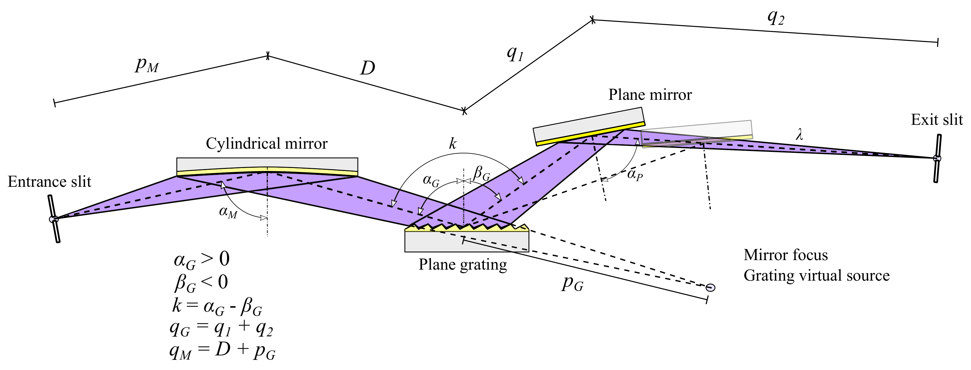
The monochromator covers a broad spectral range through the selection of one among two or more interchangeable plane gratings (PGs), illuminated along the direction perpendicular to the grooves by the converging rays coming from a focusing cylindrical mirror (CM). The diffracted light is then reflected by a plane mirror (PM) toward a vertical exit slit acting as the filtering element. The PM optic can translate and rotate—this is required to maintain the spectral focus at the same position of the slit plane when the grating subtended angle is changed. A schematic layout of the design is shown in Figure 1. The realized configuration only cares for the tangential focus (i.e., on the plane of the spectral dispersion) provided by the CM. In the sagittal direction (i.e., perpendicular to the tangential one) the rays are assumed to be collimated by a preliminary mirror, as explained in Section 4.
For each wavelength of interest, tangential aberrations on the focal plane must be minimized to obtain a high resolution. The condition to have the spectral focus on the slit plane is
where and are the grating incidence and diffraction angles, respectively. This condition must be fulfilled for each wavelength within the spectral interval of operation and can be expressed in terms of the grating subtended angle as
where is the groove density, m is the internal diffraction order (), and and are, respectively, the entrance and exit arms of the PG, as reported in Figure 1.
From Equation (2), the subtended angle k is calculated for each wavelength of interest and changed by translating the PM along an axis parallel to the beam output direction and rotating it around an axis passing through its center, as reported in Figure 2b. The variation of the length of due to the translation of the plane mirror, i.e., the variation of the distance between the grating and the exit slit is almost negligible at grazing incidence.
Tangential coma is the second main undesired aberration once the spectral defocusing has been corrected. This specific design allowed us to select the entrance arm of the CM to have the coma given by the grating compensated by the coma that is specifically introduced by the mirror. Reference [21] shows that the condition for coma compensation at the specific wavelength is given by
where D is the mirror-to-grating distance, and and are the grating incidence and diffraction angles at the wavelength , respectively. The coefficient is given by
The output bandwidth at full-width-at-half-maximum (FWHM) is defined as
where is the exit slit aperture. The optimal condition for no loss of flux is obtained by the following relation between the entrance and exit slits apertures
where the three multiplication factors which give the projection of the entrance slit to the exit slit plane are, respectively: The mirror magnification , the grating magnification , and the grating anamorphic factor .
2.2. Parameter Selection
The design has been demonstrated in the 12–50 eV region. Two gold-coated gratings manufactured by Newport-Richardson Gratings™ were used, respectively, with 600 gr/mm () and 1200 gr/mm (), both of them with nominal blaze angle. The coma-correction energies were 20.6 eV (60 nm) and 41.3 eV (30 nm), respectively, for G1 and G2. The subtended angle at was selected equal to .
Further parameters, such as the grating output arm , the mirror-to-grating distance D, and the CM incidence angle were selected to satisfy both spectral bandwidth (Section 3.3) and compact realization requirements. Monochromator parameters are reported in Table 1.
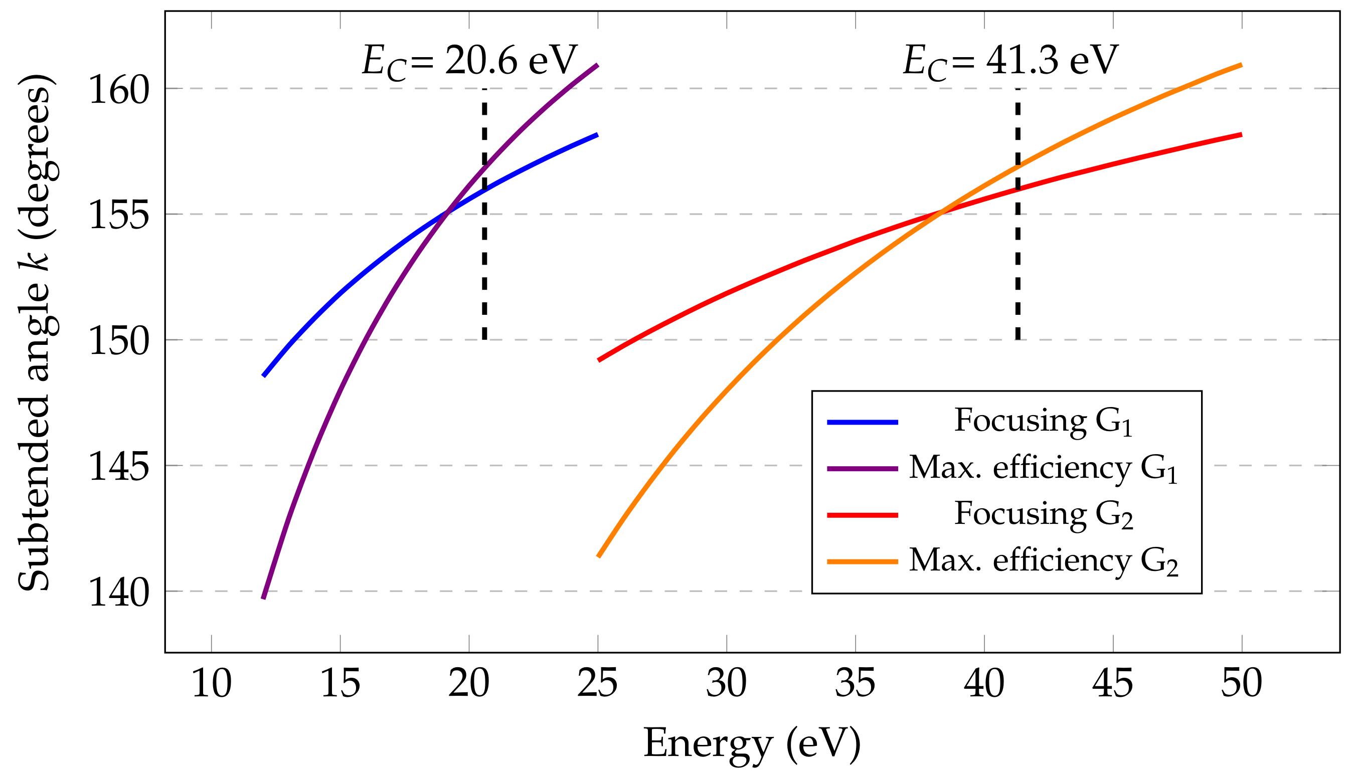
Once the geometrical design was defined, the subtended angles (reported in Figure 3) and the FWHM energy bandwidth were calculated, from Equations (2) and (6), respectively, for the entire spectral range of the two gratings.
The entrance slit width was set to about 35 ± 3 m, which is the typical width of a HHs source, with the laser focused tightly to reach sufficient intensity to ionize the gas [22].
3. Characterization Results
3.1. Spectral Characterization
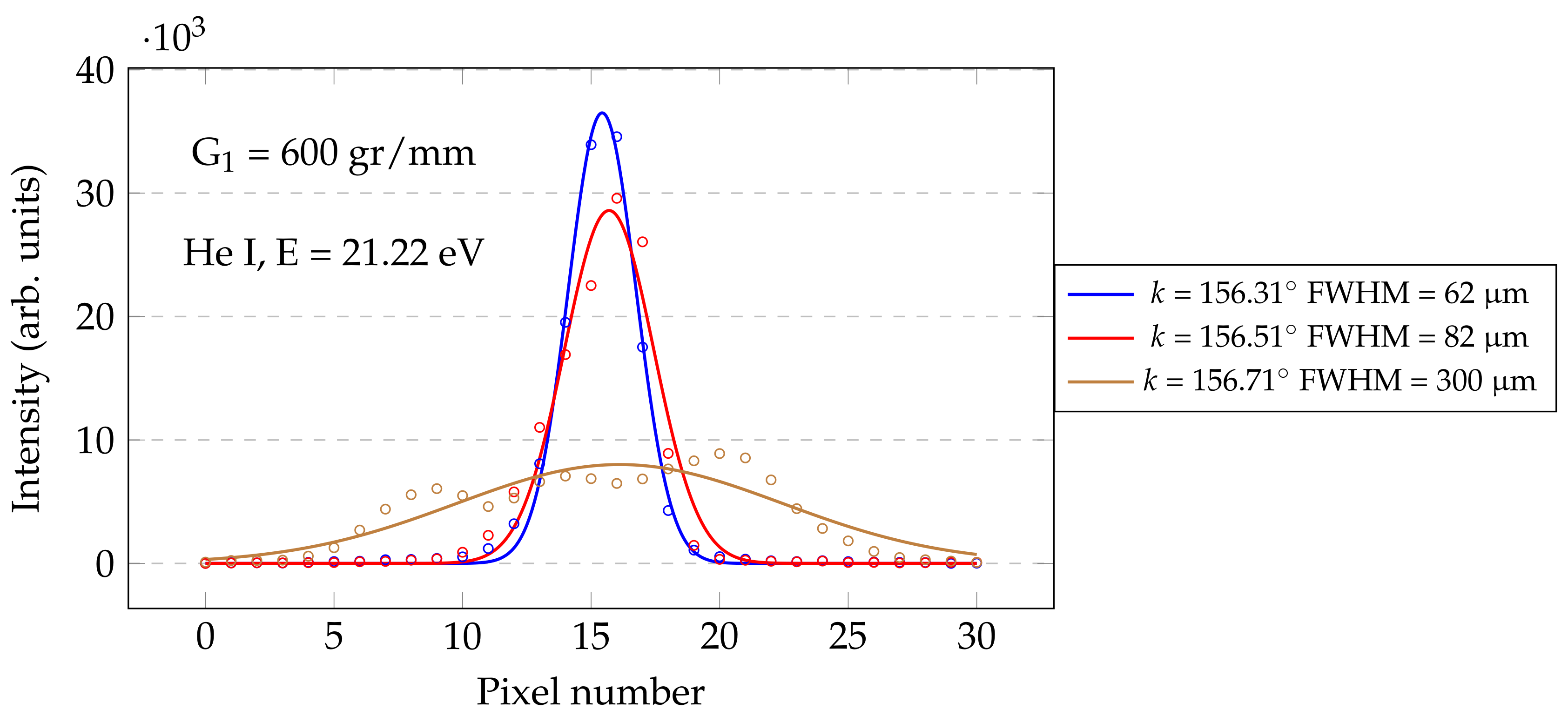
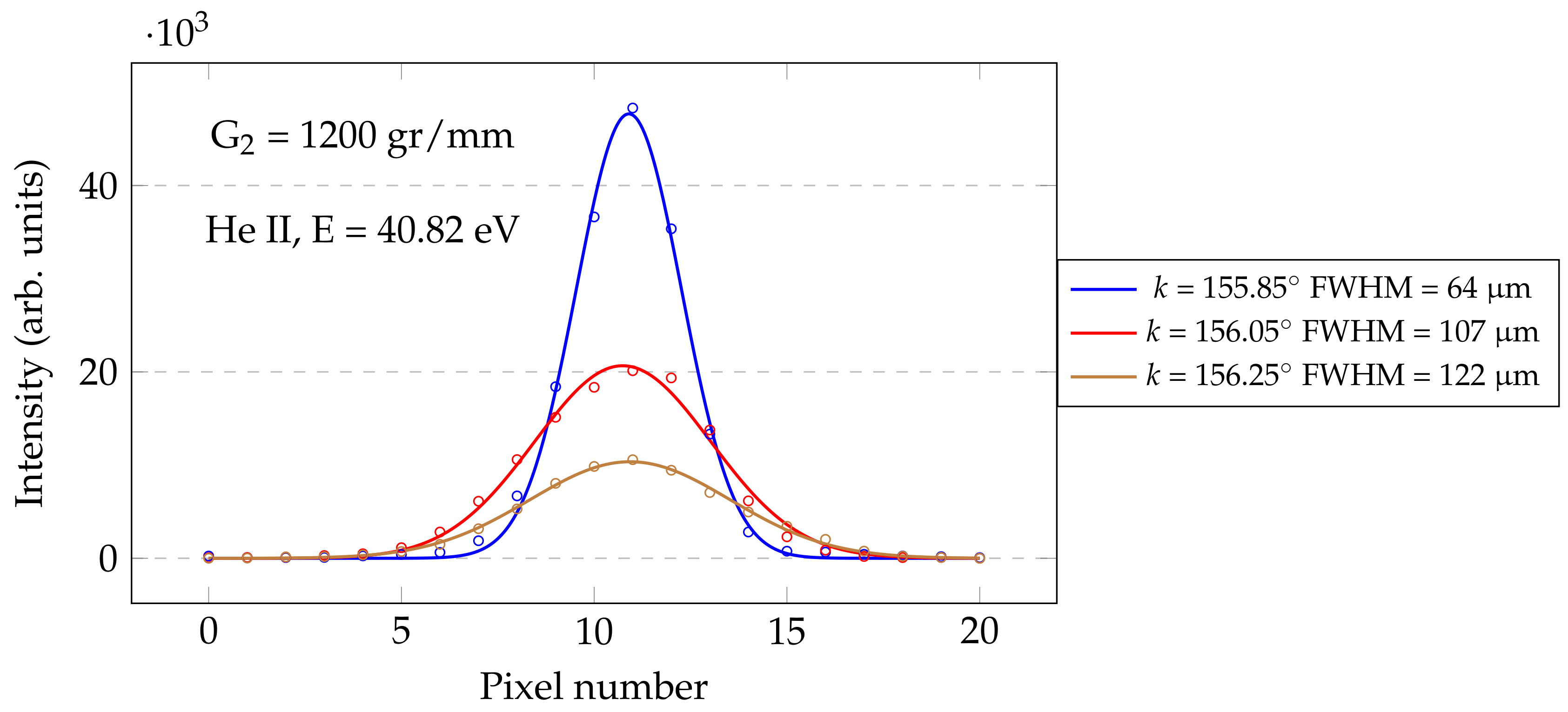
The spectral characterization of the monochromator was performed using the discrete emission lines in the 12.4–50 eV energy range of a gas-discharge lamp (filled with different noble gases—He, Ne, and Ar). A vacuum level of mbar was maintained inside the monochromator chamber, even when the gas-discharge lamp was turned on. All the measurements were performed using a cooled CCD camera detector (Princeton Instruments PIXIS) with low read-out noise ( rms), placed in the image plane, i.e., with the exit slit completely open, in a spectrometer fashion. The CCD format was pixels, with 20 m × 20 m pixel size, determining the resolution of the detection. The evaluation of the tangential defocusing aberration was performed by a Gaussian interpolation of the acquired CCD spectral image, before and after a variation of k from its nominal position (associated to a specific photon energy) of 0.2° and 0.4°. In Figure 4 and Figure 5, the emission lines of He I (1s2 → 1s2p) at 21.22 eV and He II (1s → 2p) at 40.82 eV are shown.
By applying Equation (6), we calculate an image width of 58 m with a 35 m entrance slit in the entire spectral range. The expression accounts for only the entrance slit magnification and not for residual aberrations. The typical width of the spectral lines at the optimum angle is in the range 60–65 m, confirming the correction of defocusing and coma given by the design. The residual mismatch between theoretical and measured values is mainly due to the uncertainty on the width of the entrance slit.
3.2. Comparison with Simulations
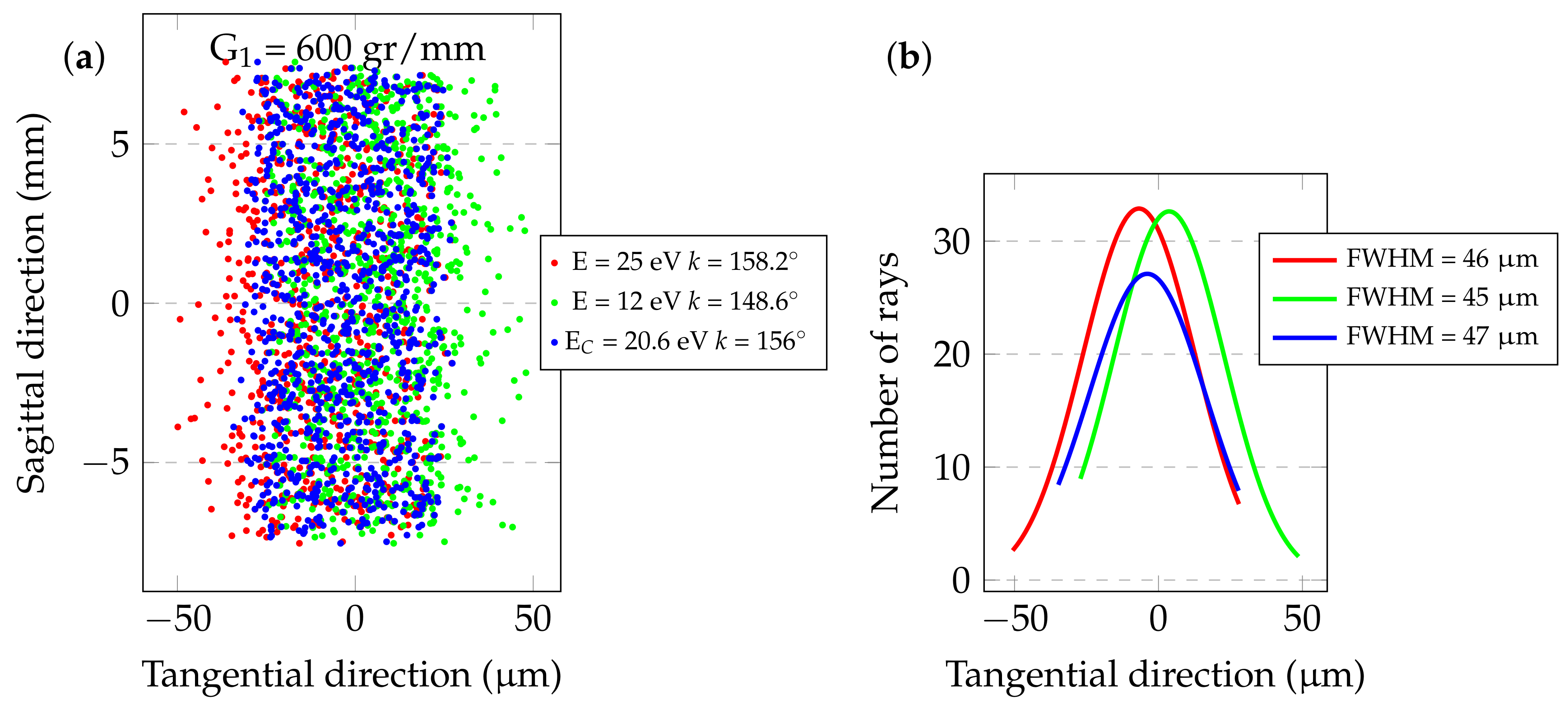
A comparison between the obtained CCD image widths in the tangential direction and the ray-tracing simulation results [23], performed with a source placed immediately before the entrance slit (assuming an angular half-divergence of 2.5 mrad × 2.5 mrad), has been performed. From Equation (5), this configuration allows for maintaining a constant value for the entrance slit magnification on the image plane within the entire spectral range. Therefore, only aberrations are responsible of a change in the image width when changing the energy. When we are not selecting , we have no defocusing, therefore the main aberration to consider is the tangential coma.
As represented in Figure 6, at the two edge energies of G1 some coma appears, as can be seen from the slightly asymmetrical images at 12 eV and 25 eV, although the width at FWHM is almost constant.
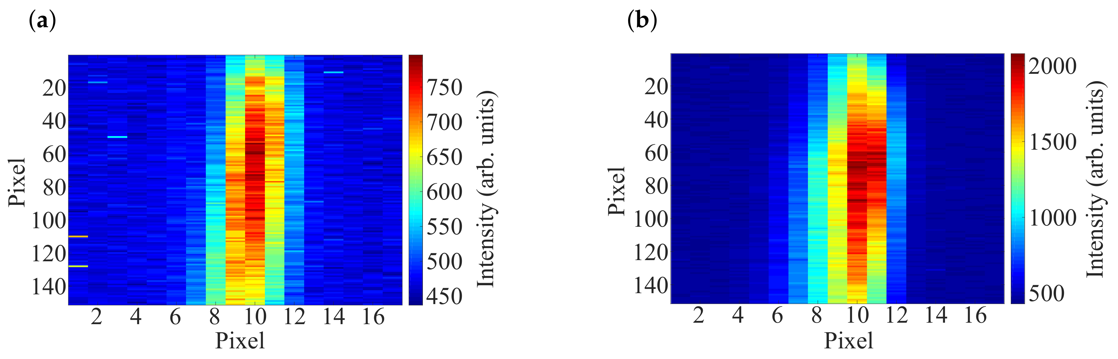
In Figure 7, the CCD acquired images at 13.48 eV (Ar II), and 21.22 eV (He I) emission lines are reported for the same grating. Coma aberration is not evident.
3.3. Resolution of the Instrument
The output bandwidth of a monochromator depends on both the widths of the entrance and exit slit. As the exit slit width is decreased, the effective bandwidth will generally decrease. If the exit slit is narrower than the projection of the entrance slit, the exit-slit-width will not reduce the bandwidth appreciably. This situation is undesirable in that diffracted energy is lost (the peak relative intensity is low) since the exit slit is too narrow to collect all of the diffracted light at once. The opposite situation is also undesirable, since the FWHM is excessively large (or, similarly, an excessively wide band of wavelengths is accepted by the wide slit). Therefore, the situation is optimal when the exit slit width matches the width of the spectral image, the relative intensity is maximized while the FWHM is minimized.
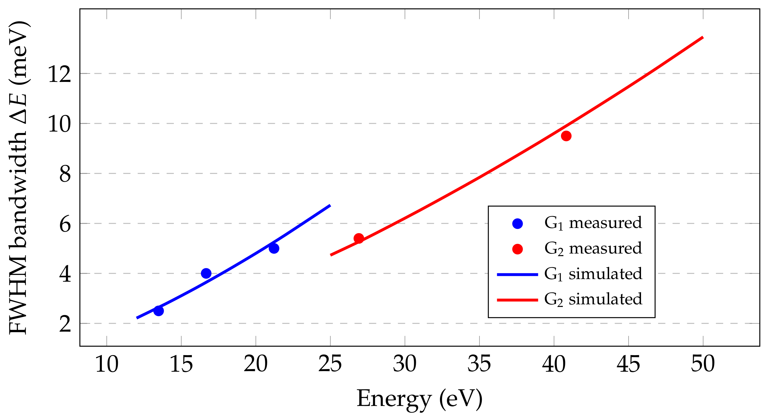
The measured spectral widths are reported in Table 2 and Figure 8 for the discrete spectral lines emitted by the source. The resulting spectral bandwidth is below 10 meV, with a ∼60 m wide projection of the entrance slit. The measured values are best fitted assuming a 37 m wide input slit, which is well within the uncertainty of the slit mounting.
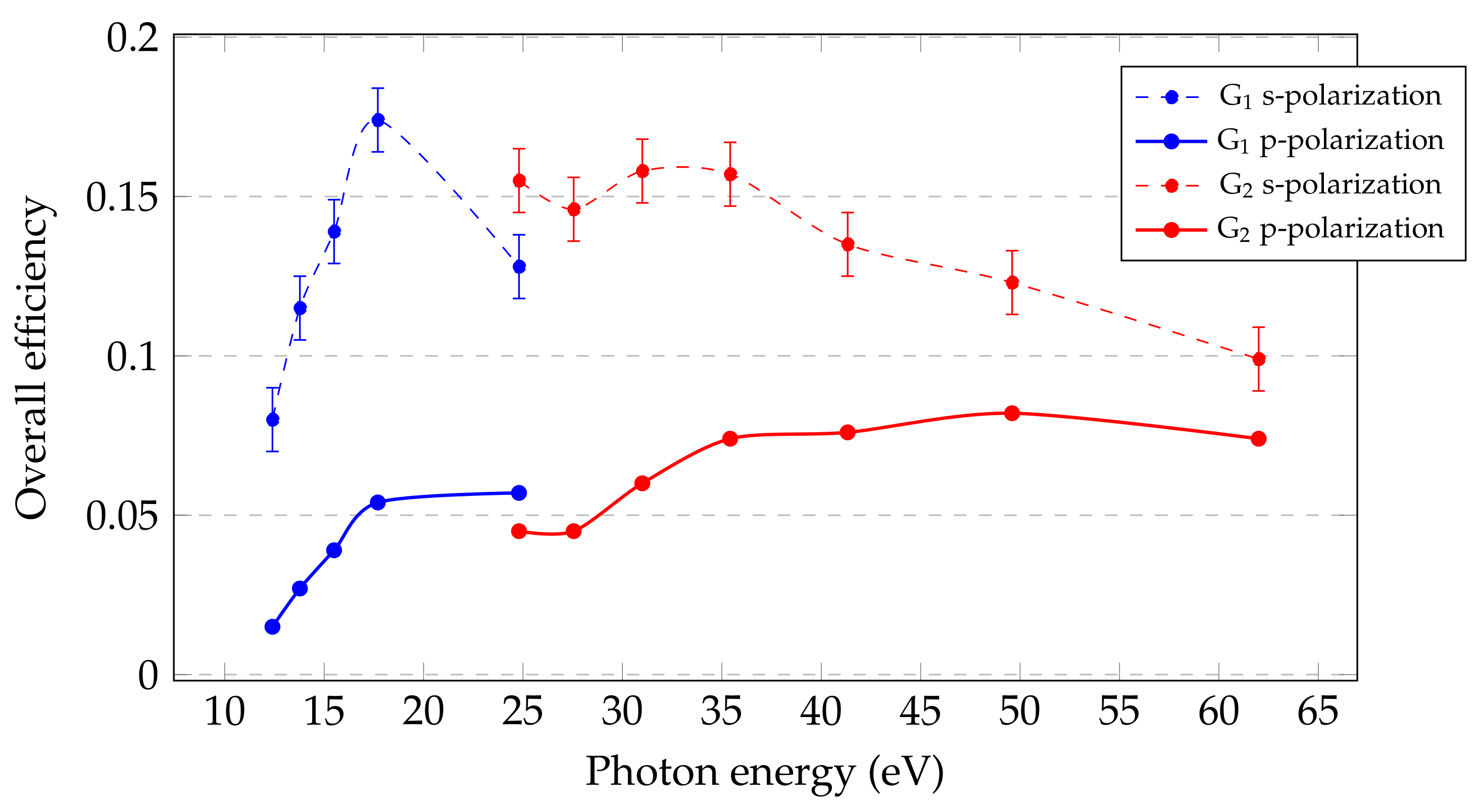
3.4. Overall Efficiency
The efficiencies of the optical elements of the configuration (i.e., focusing mirror, plane grating, and plane mirror) were measured in the 12–62 eV region at the Circular Polarization (CiPo) beamline at ELETTRA Synchrotron [24]. The total efficiency of the instrument, defined as the product of the grating diffraction efficiency and the mirrors reflectivity was measured. As shown in Figure 9, the efficiency of the monochromator for s-polarized light is in the 8–15% (in percentage) range. The efficiency of gratings is between 13–27%. The theoretical efficiency for p-polarized light was obtained by combining simulations with s-polarization experimental results. During the measurements, for each photon energy, the two gratings performed the spectral selection at the subtended angle k for which the tangential defocusing is corrected. In order to retrieve the efficiency, the optics were positioned on an X-ray reflectometer [25] which was installed at the output of the beamline.
Given that the grating was used at a variable subtended angle, the loss of efficiency due to the introduction of the additional plane mirror was almost recovered because it was maintained close to the blaze condition of maximum efficiency during the full wavelength scan (as represented in Figure 3).
4. Application to HHs Selection
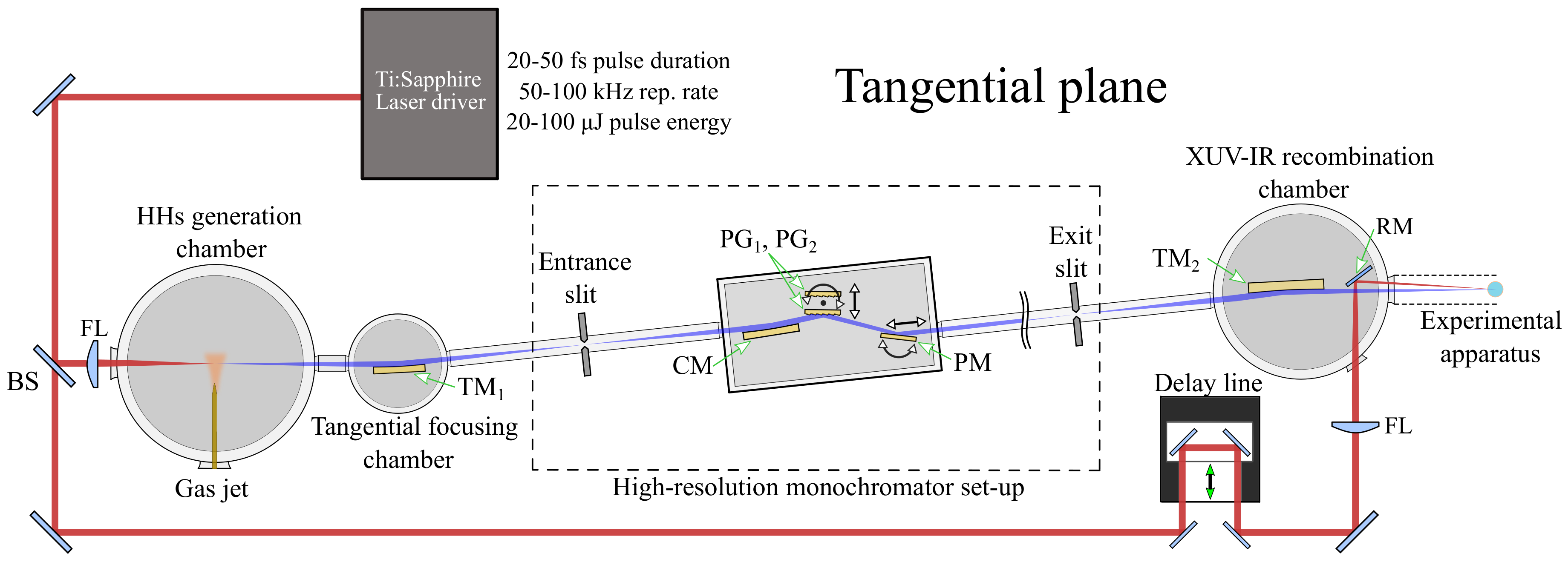
As schematized in Figure 10, the high vacuum chamber containing the entire monochromator set-up, made up of three optical elements, can be used for high-resolution applications dedicated to pump-probe IR-XUV experiments. After HHs gneration, a preliminary toroidal mirror TM1 with equal entrance and exit arms (1:1 configuration) in order to minimize aberrations, was used for the XUV-beam focusing on the entrance slit in the tangential (dispersion) direction. Similarly, after the monochromator exit slit, the toroidal mirror TM2 in the XUV-IR recombination chamber acts as a focusing mirror to the experimental apparatus. The output arm has to be long enough to accommodate such a chamber. In addition, this mirror is operated in the 1:1 configuration. The total length of the high-resolution monochromator set-up (between entrance and exit slit) is about 3 m. The focus in the plane parallel to the slits, i.e., the sagittal plane, is assured by a suitable choice of the sagittal radii of the two toroidal mirrors—the first mirror TM1 collimates the source beam in the vertical direction and the second mirror TM2 focuses it. These mirrors are assumed to be operated at incidence angles grater than 86° in order to have high reflectivity and high insensitivity to the polarization of the incoming light. The arms are chosen typically equal to 700 mm for both mirrors, in order to avoid a degradation of TM1 caused by a high XUV flux.
5. Conclusions
The performance of a three-elements grazing-incidence monochromator designed for high spectral resolution HHs experiments are presented. The optical configuration uses a plane grating illuminated by the light converging from a concave focusing mirror. The set-up maintains the spectral focus in a fixed position on the output-slit-plane by changing the subtended angle on the grating. The realized monochromator works in the 12–50 eV region. An output bandwidth lower than 10 meV has been achieved in the whole region of operation. When compared with synchrotron PGMs, for which the working range is between 60–410 eV, comparable performances in terms of resolution (5000–20,000) and efficiency have been obtained. The peculiarity of this design is related to the cost-to-benefit ratio. Since all the optical components used in the monochromator are available on the market with high optical quality and modest prices, the configuration can be useful for cost-effective instrumentation, both on synchrotron beamlines and on novel laboratory-based applications using HHs sources at high-repetition rates.
Author Contributions
N.F. wrote the paper and performed the ray-tracing simulations; L.P. conceived the optical configuration and coordinated all the activities; N.F., F.F., and P.M. performed the instrument characterization.
Acknowledgments
The results presented in the paper have been partially funded by Extreme Light Infrastructures (ELI) funds of the Italian Ministry for Education, University and Research. The authors would like to thank Carlo Spezzani for his support on the efficiency measurements performed at ELETTRA Synchrotron.
Conflicts of Interest
The authors declare no conflict of interest.
References
- Corder, C.; Zhao, P.; Bakalis, J.; Li, X.; Kershis, M.D.; Muraca, A.R.; White, M.G.; Allison, T.K. Ultrafast extreme ultraviolet photoemission without space charge. Struct. Dyn. 2018, 5, 054301. [Google Scholar] [CrossRef] [PubMed]
- Buss, J.H.; Wang, H.; Xu, Y.; Maklar, J.; Joucken, F.; Zeng, L.; Stoll, S.; Jozwiak, C.; Pepper, J.; Chuang, Y.; et al. A setup for extreme-ultraviolet ultrafast angle-resolved photoelectron spectroscopy at 50-kHz repetition rate. Rev. Sci. Instrum. 2019, 90, 023105. [Google Scholar] [CrossRef] [PubMed]
- Nie, Z.; Turcu, I.C.E.; Li, Y.; Zhang, X.; He, L.; Tu, J.; Ni, Z.; Xu, H.; Chen, Y.; Ruan, X.; et al. Spin-ARPES EUV Beamline for Ultrafast Materials Research and Development. Appl. Sci. 2019, 9, 370. [Google Scholar] [CrossRef]
- Yost, D.C.; Schibli, T.R.; Ye, J. Efficient output coupling of intracavity high-harmonic generation. Opt. Lett. 2008, 33, 1099–1101. [Google Scholar] [CrossRef] [PubMed]
- Zhao, Z.; Ozawa, A.; Kuwata-Gonokami, M.; Kobayashi, Y. Efficient high harmonics generation by enhancement cavity driven with a post-compressed FCPA laser at 10 MHz. High Power Laser Sci. Eng. 2018, 6, E19. [Google Scholar] [CrossRef]
- Hädrich, S.; Klenke, A.; Rothhardt, J.; Krebs, M.; Hoffmann, A.; Pronin, O.; Pervak, V.; Limpert, J.; Tünnermann, A. High photon flux table-top coherent extreme-ultraviolet source. Nat. Photonics 2014, 8, 779–783. [Google Scholar] [CrossRef] [Green Version]
- Torelli, P.; Sacchi, M.; Cautero, G.; Cautero, M.; Krastanov, B.; Lacovig, P.; Pittana, P.; Sergo, R.; Tommasini, R.; Fondacaro, A.; et al. Experimental setup for high energy photoemission using synchrotron radiation. Rev. Sci. Instrum. 2005, 76, 023909. [Google Scholar] [CrossRef]
- Harter, J.W.; King, P.D.C.; Monkman, E.J.; Shai, D.E.; Nie, Y.; Uchida, M.; Burganov, B.; Chatterjee, S.; Shen, K.M. A tunable low-energy photon source for high-resolution angle-resolved photoemission spectroscopy. Rev. Sci. Instrum. 2012, 83, 113103. [Google Scholar] [CrossRef] [Green Version]
- Frassetto, F.; Fabris, N.; Miotti, P.; Poletto, L. Design Study of Time-Preserving Grating Monochromators for Ultrashort Pulses in the Extreme-Ultraviolet and Soft X-Rays. Photonics 2017, 4, 14. [Google Scholar] [CrossRef]
- Padmore, H.A.; Howells, M.R.; McKinney, W.R. Grazing-Incidence Monochromators for Third-Generation Synchrotron Radiation Sources. In Vacuum Ultraviolet Spectroscopy II; Samson, J.A., Ederer, D.R., Eds.; Elsevier: Amsterdam, The Netherlands, 1999; pp. 21–54. [Google Scholar]
- Underwood, J.H. Spectrographs and Monochromators Using Varied Line Spacing Gratings. In Vacuum Ultraviolet Spectroscopy II; Samson, J.A., Ederer, D.R., Eds.; Elsevier: Amsterdam, The Netherlands, 1999; pp. 55–72. [Google Scholar]
- Hoffmann, S.V.; Søndergaard, C.; Schultz, C.; Li, Z.; Hofmann, P. An undulator-based spherical grating monochromator beamline for angle-resolved photoemission spectroscopy. Nucl. Instr. Meth. Phys. Res. Sect. A 2004, 523, 441–453. [Google Scholar] [CrossRef]
- Poletto, L.; Tondello, G. Spherical-grating monochromator with a variable-line-spaced grating for synchrotron radiation. Appl. Opt. 2000, 39, 5671–5678. [Google Scholar] [CrossRef] [PubMed]
- Peatman, W.B.; Bahrdt, J.; Eggenstein, F.; Reichardt, G.; Senf, F. The exactly focusing spherical grating monochromator for undulator radiation at BESSY. Rev. Sci. Instrum. 1995, 66, 2801–2806. [Google Scholar] [CrossRef]
- Malcolm, R.H. Plane grating monochromators for synchrotron radiation. Nucl. Instrum. Methods 1980, 177, 127–139. [Google Scholar] [Green Version]
- Petersen, H.; Senf, F.; Schäfers, F.; Bahrdt, J. Monochromators for the undulator U49 at the BESSY II storage ring. Rev. Sci. Instrum. 1995, 66, 1777–1779. [Google Scholar] [CrossRef]
- Petersen, H. The Plane Grating and Elliptical Mirror: A New Optical Configuration for Monochromators. Opt. Commun. 1982, 40, 402–406. [Google Scholar] [CrossRef]
- Lu, L.; Cocco, D.; Jark, W. Simple plane grating monochromator for synchrotron radiation. Nucl. Instr. Meth. Phys. Res. Sect. A 1994, 339, 604–609. [Google Scholar]
- Hettrick, M.C.; Bowyer, S. Varied line-space gratings: new designs for use in grazing incidence spectrometers. Appl. Opt. 1983, 22, 3921–3924. [Google Scholar] [CrossRef] [PubMed]
- Itou, M.; Harada, T.; Kita, T. Soft x-ray monochromator with a varied-space plane grating for synchrotron radiation: design and evaluation. Appl. Opt. 1989, 28, 146–153. [Google Scholar] [CrossRef]
- Poletto, L.; Frassetto, F. Cost-effective plane-grating monochromator design for extreme-ultraviolet application. Appl. Opt. 2018, 57, 1202–1211. [Google Scholar] [CrossRef]
- Chen, M.-C.; Gerrity, M.R.; Backus, S.; Popmintchev, T.; Zhou, X.; Arpin, P.; Zhang, X.; Kapteyn, H.C.; Murnane, M.M. Spatially coherent, phase matched, high-order harmonic EUV beams at 50 kHz. Opt. Express 2009, 17, 17376–17383. [Google Scholar] [CrossRef]
- Del Rio, M.S.; Canestrari, N.; Jiang, F.; Cerrina, F. SHADOW3: a new version of the synchrotron X-ray optics modelling package. J. Synchrotron Radiat. 2011, 18, 708–716. [Google Scholar] [CrossRef] [PubMed]
- Desiderio, D.; Difonzo, S.; Dlviacco, B.; Jark, W.; Krempasky, J.; Krempaska, R.; Lama, F.; Luce, M.; Mertins, H.C.; Placentini, M.; et al. The elettra circular polarization beamline and electromagnetic elliptical wiggler insertion device. Synchrotron Radiat. News 1999, 12, 34–38. [Google Scholar] [CrossRef]
- Sacchi, M.; Spezzani, C.; Torelli, P.; Avila, A.; Delaunay, R.; Hague, C.F. Ultrahigh-vacuum soft X-ray reflectometer. Rev. Sci. Inst. 2003, 74, 2791. [Google Scholar] [CrossRef]
Figure 1.
Tangential layout of the monochromator referred to the dispersion (spectral plane). The cylindrical mirror focus is placed after the grating. In order to maintain the final focal point at the same position, a variation of the grating subtended angle and the related translation and rotation of the plane mirror are required.

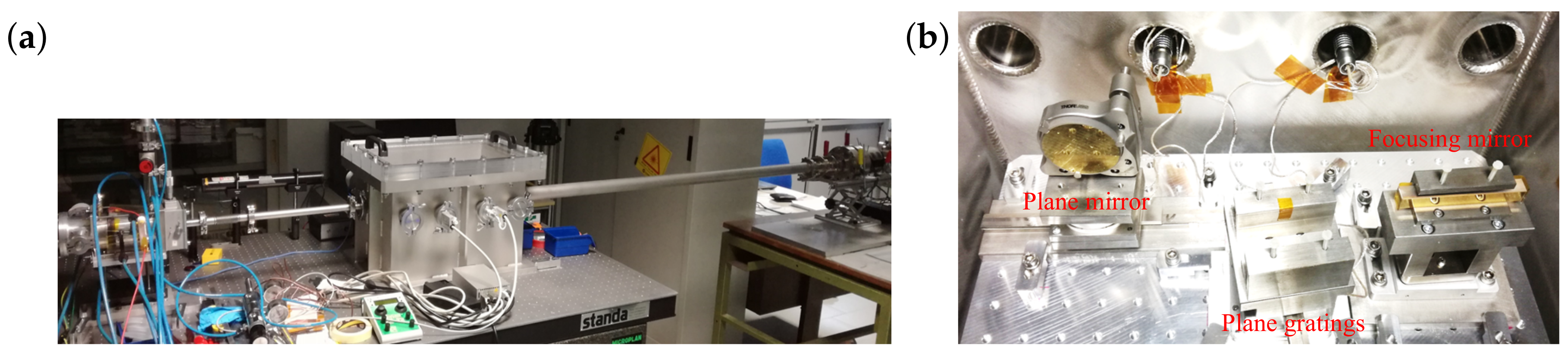
Figure 2.
(a) External and (b) internal view of the three-elements monochromator vacuum chamber.

Figure 3.
Comparison between the subtended angles for focusing condition and maximum efficiency.

Figure 4.
Line profile for k variation of 0.2 and 0.4 at 21.22 eV, grating.

Figure 5.
Line profile for k variation of 0.2 and 0.4 at 40.82 eV, grating.

Figure 6.
Ray-tracing results of the entrance slit projected to the output for the values given in Table 1 (G1 grating). (a) Image shape for three different energies and (b) width in the tangential direction.
Figure 6.
Ray-tracing results of the entrance slit projected to the output for the values given in Table 1 (G1 grating). (a) Image shape for three different energies and (b) width in the tangential direction.

Figure 7.
Acquired CCD images at the image plane of two emission lines selected by the G1 grating. (a) 13.48 eV; and (b) 21.22 eV.
Figure 7.
Acquired CCD images at the image plane of two emission lines selected by the G1 grating. (a) 13.48 eV; and (b) 21.22 eV.

Figure 8.
Full-width-at-half-maximum (FWHM) bandwidth measured on the exit slit plane (dot-points) and theoretical best-fit assuming a 37 m entrance slit (solid lines).
Figure 8.
Full-width-at-half-maximum (FWHM) bandwidth measured on the exit slit plane (dot-points) and theoretical best-fit assuming a 37 m entrance slit (solid lines).

Figure 9.
Experimental total efficiency of the monochromator for s-polarized light (dashed) and theoretical for p-polarized light (solid). For each measurement, the subtended angle has been selected to satisfy the tangential focus condition.
Figure 9.
Experimental total efficiency of the monochromator for s-polarized light (dashed) and theoretical for p-polarized light (solid). For each measurement, the subtended angle has been selected to satisfy the tangential focus condition.

Figure 10.
Top-view schematic representing the insertion of the high-resolution monochromator within a high-repetition rate beamline dedicated to pump–probe experiments. The system includes a laser system and optics, the XUV beamline, and the IR delay-line. BS, beam splitter; FL, piano-convex focusing lens; TM1, tangential focusing and sagittal collimating toroidal mirror; CM, tangential focusing cylindrical mirror; PG1-PG2, interchangeable rotating plane gratings; PM, rotating–translating plane mirror; TM2, tangential focusing and sagittal focusing toroidal mirror; RM, IR recombination mirror.


Table 1.
Parameters of the monochromator.
| Entrance Slit Dimensions | 35 μm × 1 mm | ||||
|---|---|---|---|---|---|
| Focusing Mirror | Gratings G1 − G2 | Plane Mirror | |||
| 675 mm | 363 mm | range | 60–200 mm | ||
| 478 mm | 2070 mm | range | 1870–2010 mm | ||
| k range | – | – | |||
| (tang. radius) | 10,700 mm | G groove density | 600 gr/mm | ||
| G1 energy range | 12–25 eV | ||||
| G2 groove density | 1200 gr/mm | ||||
| G2 energy range | 25–50 eV | ||||
| D | 115 mm | ||||
Table 2.
Widths of the spectral lines measured on the exit slit plane.
| Energy (eV) | Grating Type | WOUT (m) | (meV) |
|---|---|---|---|
| 13.48 | G1 | 60 | 2.5 |
| 16.67 | G1 | 70 | 4.0 |
| 21.22 | G1 | 60 | 5.0 |
| 26.91 | G2 | 65 | 5.4 |
| 40.82 | G2 | 60 | 9.5 |
© 2019 by the authors. Licensee MDPI, Basel, Switzerland. This article is an open access article distributed under the terms and conditions of the Creative Commons Attribution (CC BY) license (http://creativecommons.org/licenses/by/4.0/).
Share and Cite
MDPI and ACS Style
Fabris, N.; Miotti, P.; Frassetto, F.; Poletto, L. A High Resolution XUV Grating Monochromator for the Spectral Selection of Ultrashort Harmonic Pulses. Appl. Sci. 2019, 9, 2502. https://doi.org/10.3390/app9122502
AMA Style
Fabris N, Miotti P, Frassetto F, Poletto L. A High Resolution XUV Grating Monochromator for the Spectral Selection of Ultrashort Harmonic Pulses. Applied Sciences. 2019; 9(12):2502. https://doi.org/10.3390/app9122502
Chicago/Turabian StyleFabris, Nicola, Paolo Miotti, Fabio Frassetto, and Luca Poletto. 2019. "A High Resolution XUV Grating Monochromator for the Spectral Selection of Ultrashort Harmonic Pulses" Applied Sciences 9, no. 12: 2502. https://doi.org/10.3390/app9122502
Note that from the first issue of 2016, this journal uses article numbers instead of page numbers. See further details here.