1. Introduction and Fundamental Considerations
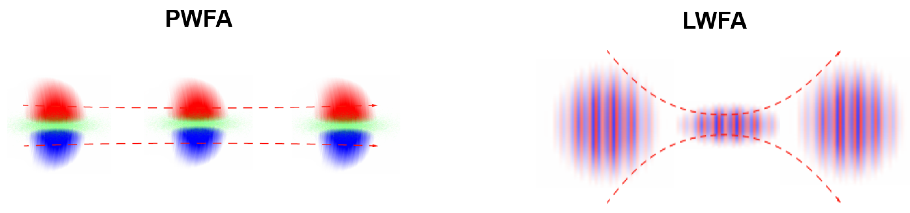
Laser-driven wakefield accelerators (LWFA) and electron-driven plasma wakefield accelerators (PWFA) rely on similar concepts [
1]. An intense laser or electron beam driver propagates through a plasma, and, based on its typically mainly transverse forces, plasma electrons are kicked out of the path of the driver beam, not unlike how a snowplough operates. However, unlike with a snowplough, these electrons then feel the re-attractive forces of the plasma ions, which have four orders of magnitude more mass than the electrons and therefore can be assumed quasistatic in first approximation. This transient charge separation follows the driver beam through the plasma and generates a co-moving plasma oscillation wave with more or less spherical geometry. The length of the arising bubble (LWFA) or blowout (PWFA) structure is determined by the plasma electron density
and the plasma wavelength
, which is solely dependent on
and where
c is the speed of light,
is the vacuum permittivity, and
is the electron mass and
e the elementary charge. In the ideal case, the driver beam length
or laser pulse duration
fits into half of the plasma wavelength such that
, because then, as with a harmonic oscillator such as a pendulum, the excitation is strongest because the driver excites the plasma wave just until the zero-crossing of the oscillatory movement. In terms of the plasma wave number
, this desirable relation between driver length
and plasma wave number
can be expressed as
.
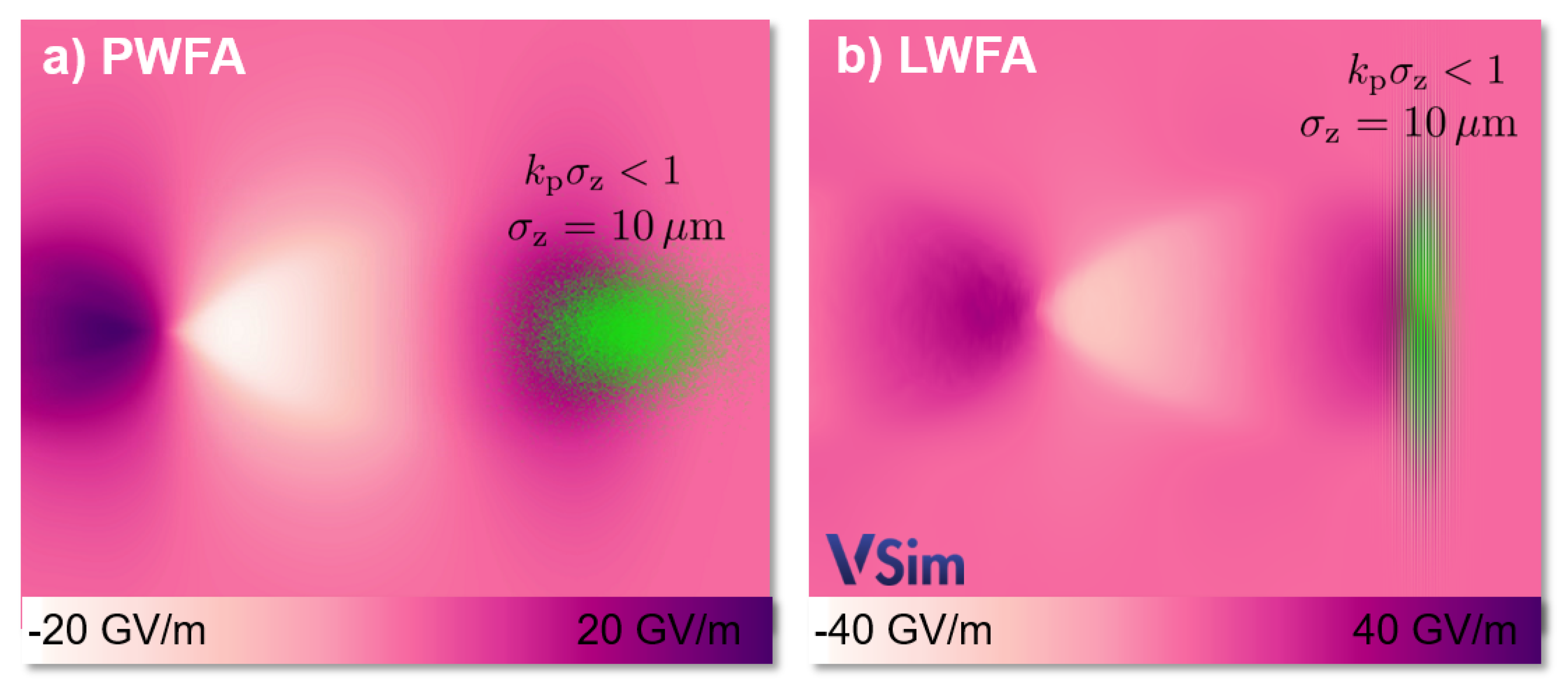
Figure 1 visualizes (based on particle-in-cell simulations with the code VSim [
2]) how the driver (green) excites a plasma blowout/bubble with large accelerating and decelerating fields up to tens of GV/m (color-coded).
Here, the plasma density is
, the corresponding plasma wavelength
m, and the plasma skin depth
m. The width of the driver pulse is in both cases set to
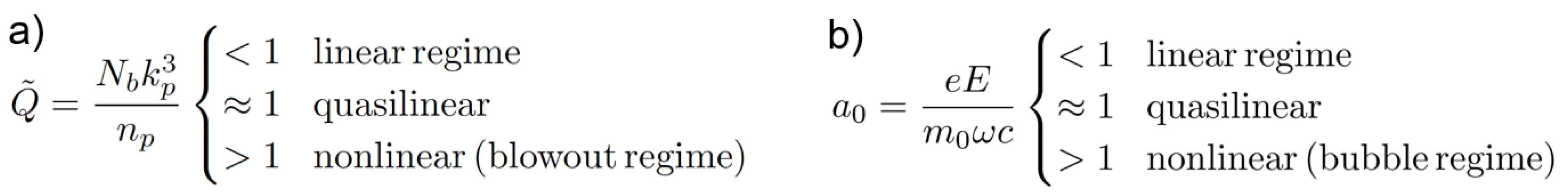
m. The strength of the driver is characterized by the dimensionless electron beam charge
and the dimensionless laser light amplitude
, respectively. Here, the dimensionless light amplitude, defined by the ratio of electric field
E and frequency
, amounts to
. The dimensionless beam charge [
3], which is defined by the ratio of the beam electron density per cubic skin depth
and the background plasma density
, where
is the classical electron radius, which is also set to
, since the values of
and
define the interaction regime of LWFA and PWFA, respectively (see
Figure 2).
Notably, the plasma density is not relevant for the type of LWFA interaction, just the laser frequency and intensity, whereas, for PWFA, . The background of this is that a particle beam has unipolar fields, while a quickly oscillating laser pulse can penetrate plasma up to the critical density , which amounts to for a typical Ti:sapphire laser pulse.
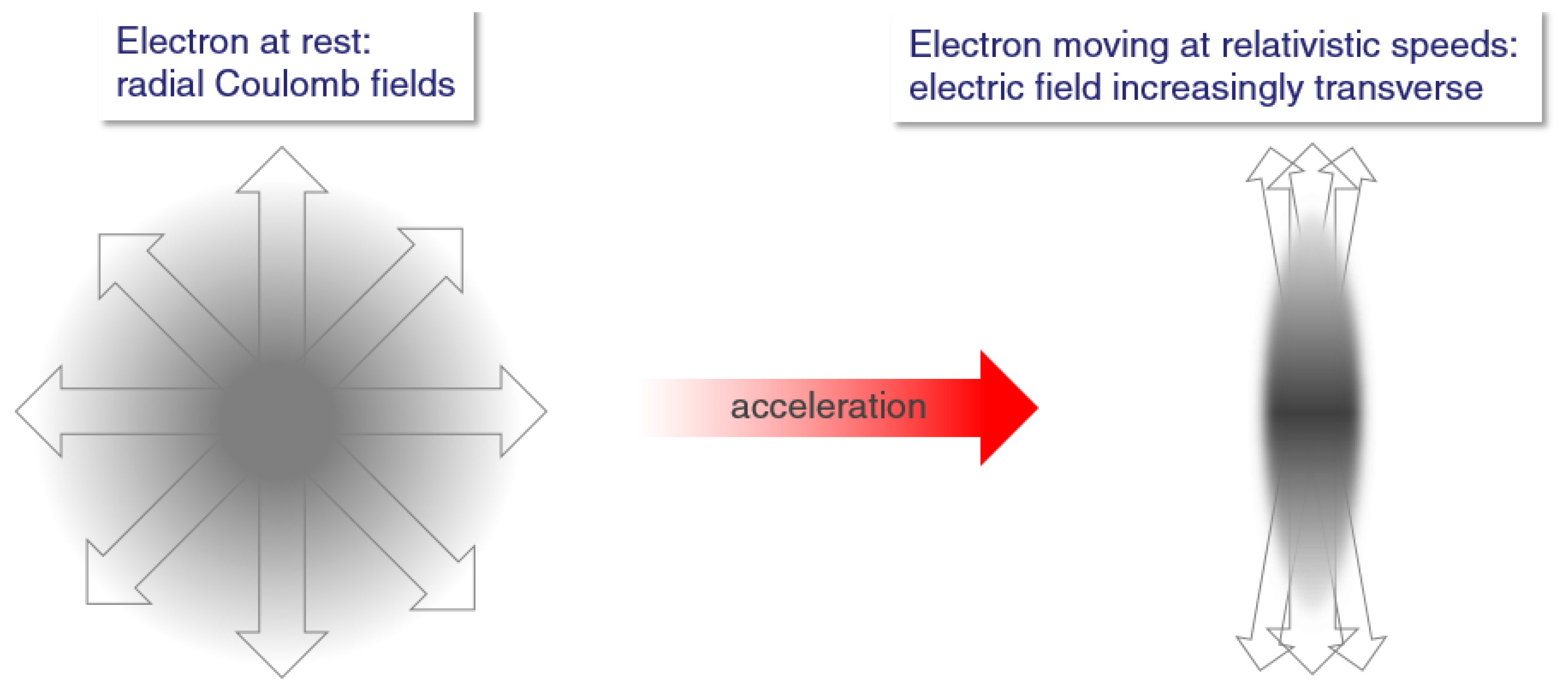
To excite the longitudinally trailing plasma wave, it is required to push plasma electrons mainly in the transverse direction as efficiently as possible. While a point charge (or an ensemble of point charges) has a radial Coulomb electric field distribution , a Lorentz transformation of the electric fields yields , such that the electric field (more accurately ) of a relativistically moving electron is mainly transversal, scaling with the Lorentz factor . For the magnetic field , we have and . The case of an electron bunch interacting with plasma is much more complex, as magnetic self-fields, return currents, etc. have to be taken into account.
Figure 3 visualizes the transverse field of an electron driver in the lab frame. The Coulomb force
of an electron bunch on plasma electrons is unipolar and scales linear with the perceived electric field. This is highly suitable in order to expel electrons off axis and to set up a plasma wave.
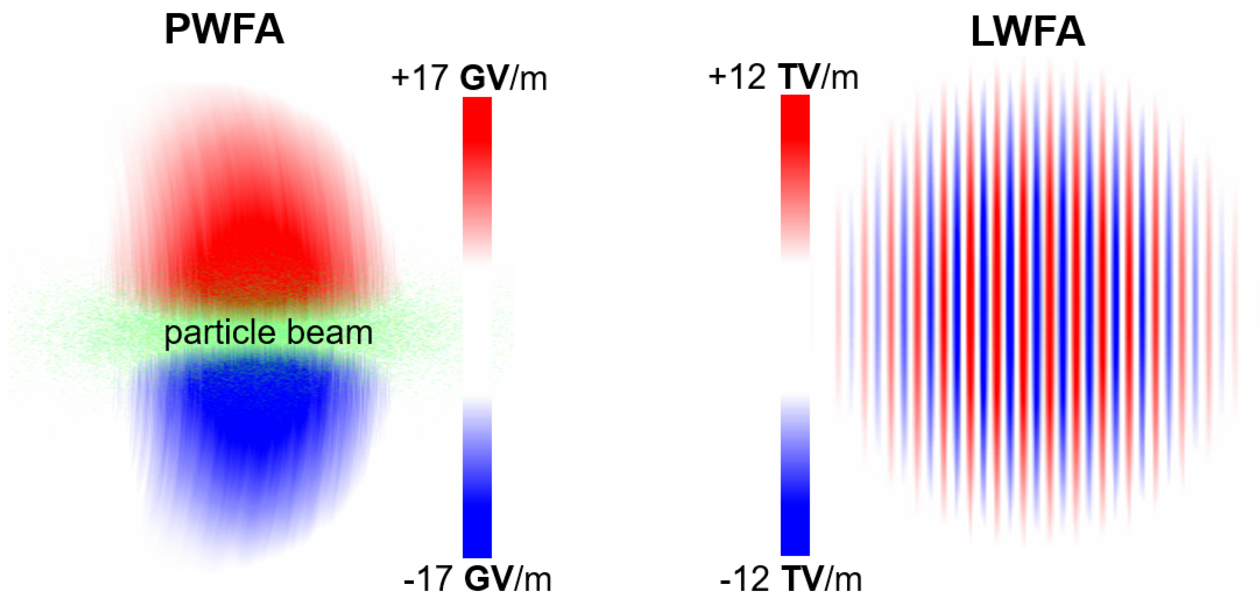
This is an important difference to laser drivers, where the electric field is not unipolar, but oscillates and puts the plasma electrons into a quiver motion. Hence, the plasma electron expulsion of electrons is achieved by means of the pondermotive force
, which scales with the gradient of the electric field squared or intensity
I. As a result, the electric fields which produce a similarly strong plasma wake excitation are orders of magnitude lower for an electron bunch PWFA driver when compared to a laser pulse LWFA driver,
. This fundamental difference is visualized in
Figure 4, showing that the electric fields of an electron bunch driver as used for
Figure 1 are three orders of magnitude lower than for a correspondingly strong laser driver as used for
Figure 1. This has important implications, in particular for the choice of media and injection mechanisms.
Now, in a bunch of particles instead of only one electron, space charge forces will make the bunch diverge, and lengthen. However, as regards lengthening or “dephasing”
of a bunch over an acceleration distance
L of a sufficiently relativistic and monoenergetic beam
such that
, the lengthening
is typically very small. While bunch lengthening is typically negligible even over meter-scale distances in vacuum, energy transfer and thus deceleration of a drive beam in plasma leads to increasing
and therefore to significant lengthening, up to the point where drive beam electrons can slow down so much that they fall back and travel from the decelerating into the accelerating phase of the blowout [
4].
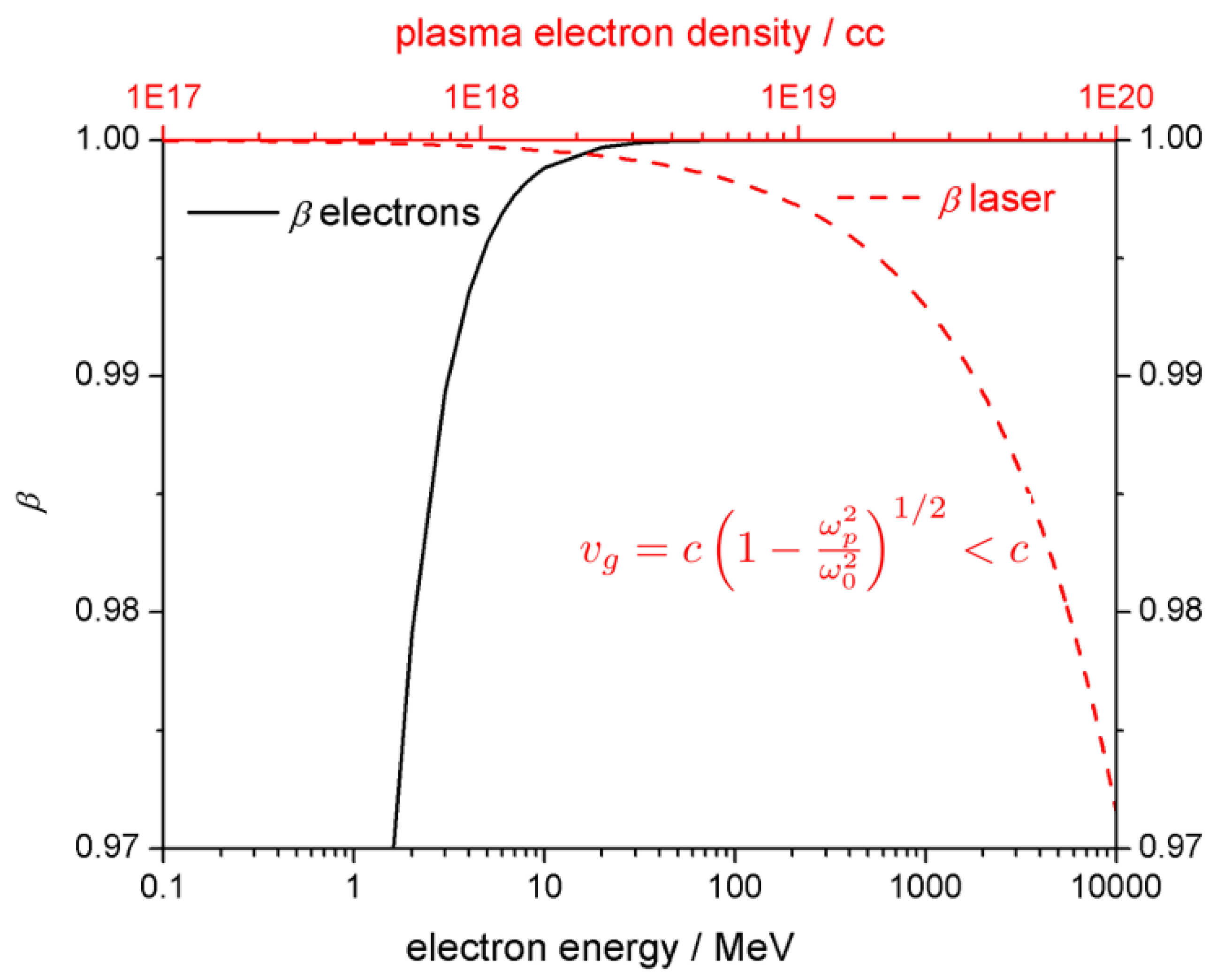
For laser pulses drivers, we have a fundamentally different situation. While an electromagnetic wave propagates with the speed of light in vacuum, in plasma the group velocity of a laser pulse is
, thus is dependent on the plasma density
via
.
Figure 5 compares velocities of electrons and laser pulses in terms of corresponding
. The energy of an electron
, and, e.g., for an electron with a kinetic energy of 0.5 MeV, the corresponding
and
, whereas, for an electron at 5 MeV, its Lorentz factor is
and
, which is already close to the speed of light.
This has an importance consequence, namely that, in LWFA, accelerated electrons will outrun the laser driver. They therefore move from the accelerating field phase in the back of the bubble forward into the decelerating field in the first part of the bubble, which limits the useful acceleration distance and hence energy gain. It is interesting to note that, as pointed out above, in LWFA, the wake excitation strength is independent of the plasma density, but the acceleration distance is, whereas in contrast in PWFA the wake excitation strength is dependent on the plasma density, but the acceleration distance is not. This is why PWFA, a sufficiently intense and energetic driver provided, can harness phase-constant, tens of GV/m-scale (or higher) accelerating fields over meter-scale distance, and hence realize tens of GeV energy gains in a single stage.
Another important aspect that arises from the different wake velocities in LWFA and PWFA regards injection and dark current, respectively. While in PWFA, due to practically negligible dephasing, the wake velocity equals the driver velocity such that for a 10 GeV driver beam, the wake velocity of the plasma wave is that of the driving laser beam such that 10–100 for typical plasma densities. A consequence of this is that electron injection and bunch generation via self-injection or other mechanisms is considerably easier to achieve in LWFA than in PWFA, while in turn it is easier to keep PWFA dark-current-free by excluding unwanted self-injection mechanisms. The general trapping condition for injected electrons is that the injected electrons have to catch up with the plasma wave such that . The Hamiltonian is the sum of a kinetic energy term and the potential energy. If injected electrons are assumed to be initially at rest, this means the electrostatic wakefield potential energy in the wave frame needs to be larger than the required electron kinetic energy . The reduced threshold for injection due to lower in LWFA is helpful if aiming at producing electron bunches on the fly, but makes it more difficult to avoid dark current, and in turn the higher threshold for injection makes it is more difficult to produce electron bunches on the fly in PWFA, but on the other hand is advantageous in order to realize a robust, dark-current free system.
As regards divergence and diffraction, both electron beams and the laser pulses expand hyperbolically when propagating in the forward direction
z. A Gaussian laser pulse focused to a spot size
exhibits diffraction following
. Similarly, for an electron beam focused to a spot size
, the transverse evolution is
. However, while the Rayleigh length
of a typical high-power Ti:sapphire laser pulse with central wavelength
m is tunable only via the spot size, which in turn needs to be small in order to yield high intensity for a given laser power, the beta function
of an electron pulse can not only be tuned via the spot size
, but also via the electron
and normalized emittance
. More importantly, it is also much larger for typical values of
and normalized emittance
. For example, for the same spot size of laser and electron beam
m, the Rayleigh range is
m for Ti:sapphire pulses, while
cm for a typical electron beam energy of 1 GeV, which corresponds to
, and a typical normalized emittance of the drive beam of
mrad. This dramatically different length over which an electron driver beam and laser pulse, respectively, stay compact, is sketched in
Figure 6. This is another main reason PWFA can straightforwardly realize substantially longer acceleration distances, and hence energy gains in a single stage, than LWFA.
It should be noted that self-focusing or active guiding, e.g., in a transversely parabolic density channel, can extend the effective Rayleigh range and hence the obtainable diffraction-limited acceleration distance of an LWFA driver pulse substantially. For an electron beam driver, there is a contribution to the divergence due to intra-bunch space charge forces. The radial Lorentz force of a particle inside the bunch is and the electric field within an (infinitely) long bunch with uniform density is given by Gauss’ law as and the magnetic field by Faraday’s law as . With , this yields . This means that transverse forces are limited, and also that for a witness bunch which is produced in a plasma wave (both driven by lasers as well as by particle beams) the transverse space charge forces quickly decrease during acceleration as . For a highly relativistic () bunch propagating in vacuum, the current-induced pinching magnetic field balances the Coulomb space charge repulsion.
However, when propagating in plasma, the repulsive electron bunch space charge forces can be shielded by the plasma electrons, such that in total a net focusing force arises due to the magnetic field. To some extent, this “plasma lens” is the equivalent of relativistic self-focusing in LWFA. In some analogy to the classification of laser propagation through plasma, one differentiates between an underdense plasma lens, where the beam density , and an overdense plasma lens where the plasma density is so high that . The underdense plasma lens, a case in the nonlinear interaction regime, is straightforward because it simply means that the plasma electrons are expelled from the vicinity of the electron beam and thus a uniform ion background shields the space charge of the beam, and the focusing strength scales linearly with ambient plasma density in principle without spherical aberrations. The head of the bunch, and depending on plasma skin depth and width and length of the bunch other parts of the bunch may not be seeing a fully uniform pure ion background. In the overdense plasma lens, the electron bunch space charge is only a small perturbation and the collective shielding by plasma electrons takes place locally and is proportional to the local bunch density. For example, in the case of a typical Gaussian electron bunch with density distribution , the peak bunch density in the center and thus the focusing strength is much larger than farther outside, which results in spherical aberrations. It helps if the bunch is long compared to the skin depth of the plasma such that , and if the beam is narrow such that .
In summary, the above considerations reveal a high degree of complementarity of LWFA and PWFA. Main features and considerations of employing laser pulses and electron beam pulses for plasma wakefield acceleration are:
Electron bunches drive plasma waves efficiently due to unidirectional fields, already at comparably low bunch self-field values such as few GV/m to tens of GV/m.
Laser pulses require large electric fields, typically in the TV/m range, to excite plasma waves via the ponderomotive force due to their oscillating field structure.
Laser pulses are very efficient to tunnel ionize matter and hence to provide plasma, due to the high peak electric laser pulse fields.
Electron bunches are not efficient for ionizing matter because of the low electric self-fields.
Electron bunches propagate with approximately the speed of light even in plasma, whereas dephasing is a fundamental problem in LWFA. This allows much longer, and phase constant acceleration to be realized in PWFA.
Electron bunches are stiff and expand transversally much less than a laser pulse of typical parameters diffracts, which allows much longer acceleration distances in PWFA.
Laser pulses quickly diffract when focused strongly, which allows the generation of locally confined hot spots for tunneling ionization and electron release.
LWFA allow various injection mechanisms, supported by the low wake velocities due to the laser pulse group velocity, but are for the same reason prone to unwanted self-injection and dark current.
Injection thresholds for PWFA are comparably high, due to the high wake velocities of dephasing free systems, but, on the other hand, PWFA for the same reason allows realizing dark-current free systems.
LWFA can be realized in ultracompact, lab-scale setups, but not yet at highest repetition rates and stability.
Linac-driven PWFA requires large facilities, but can provide bunches with high stability at high repetition rate.
LWFA inherently generates beams with very high currents, but not extremely low energy spreads, both due to the small plasma cavity sizes and large field gradients.
These features, advantages and disadvantages of LWFA and PWFA are highly complementary.
2. Hybrid Combinations of LWFA and PWFA
The complementary features of laser beams, particle beams and LWFA and PWFA can be exploited. For example, using a laser pulse to pre-ionize the plasma for a PWFA stage is an obvious method to harness both the ability of laser pulses to tunnel ionize at comparably low intensities, and to make use of the long, dephasing-free acceleration distances achievable by PWFA. However, there are many other interesting hybrid permutations, and combinations of hybrid building blocks, which are more complicated than LWFA or PWFA alone, but allow achieving extremely high electron beam quality and tunability. A fundamental subset result of the above discussion and comparison of features of LWFA and PWFA is that:
High-current electron beams are ideal drivers for plasma waves.
Laser pulses are ideal to produce dense, high current electron bunches in compact setups.
It is therefore a very attractive option to design and optimize an LWFA stage such that the electron output can be harnessed to drive an attached PWFA stage. This principle has been suggested to exploit purposefully in [
4], where “Monoenergetic Energy Doubling in a Hybrid Laser-Plasma Wakefield Accelerator” was proposed. A more or less sharp transition from LWFA to PWFA may occur also in a single plasma stage [
5,
6,
7] when dephasing is reached and/or when laser pulse power depletion and/or diffraction sets in.
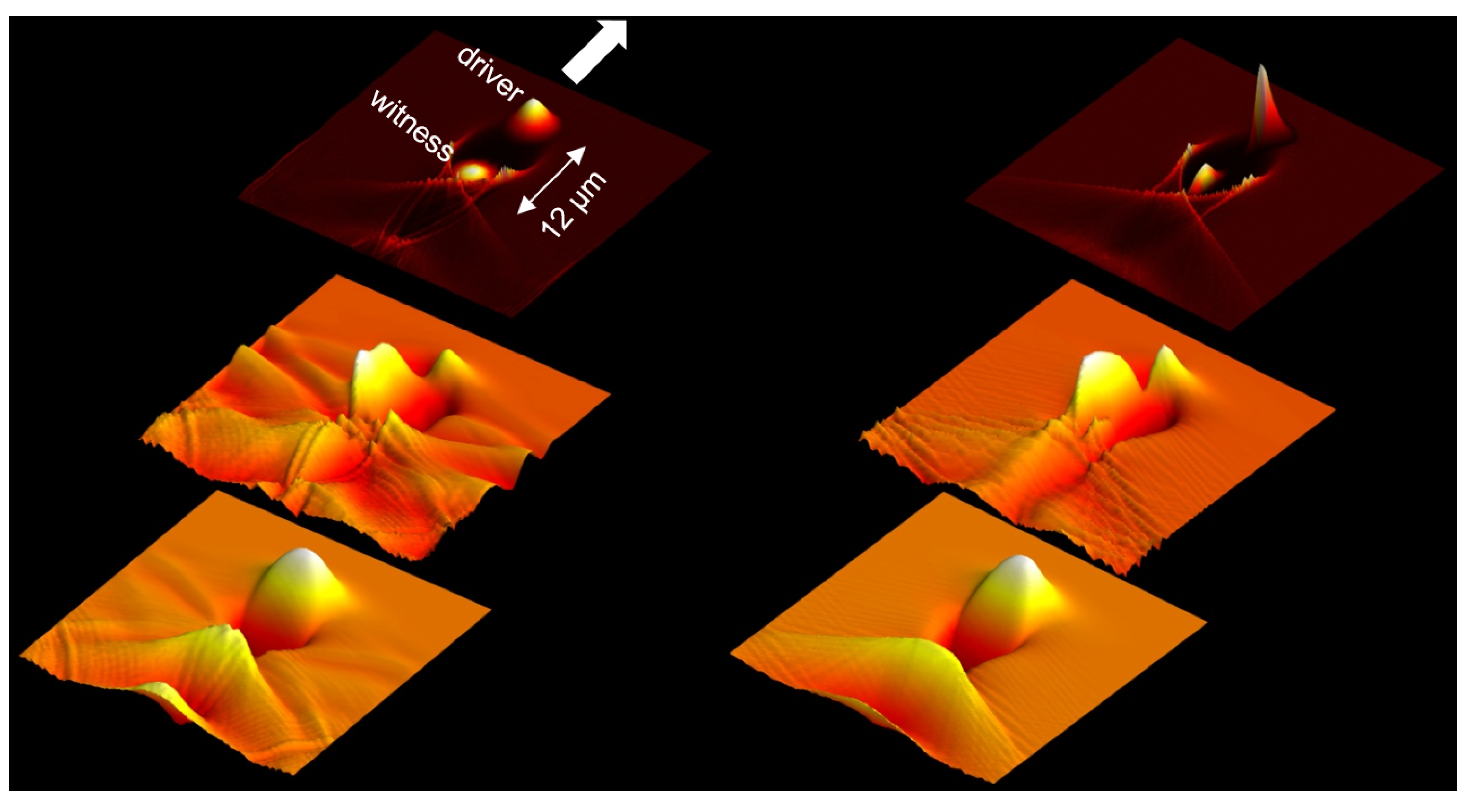
Figure 7 shows, based on PIC-simulations with OOPIC, how an electron double bunch from an LWFA stage is energy boosted in a driver-witness type PWFA stage.
The key requirement for an electron bunch to drive a strong PWFA wakefield stage is its current. The energy spread of electron beam drivers is less important, because as described above for sufficiently relativistic electrons the phase slippage or bunch lengthening is small and not a primary concern. On the contrary, it is well-known that in a process called BNS damping [
8] an energy spread can suppress instabilities such as the beam breakup (BBU) instability and hosing. While the energy transfer of the drive beam to the plasma will introduce an energy spread even if initially perfectly monoenergetic, it helps if the drive beam has a significant energy spread right from the beginning of the PWFA process [
9]. This is a feature which LWFA can realize very well: produce inherently ultrashort, multi-kA electron bunches [
10,
11,
12] with significant energy spreads in very compact setups. Significant energy spread of LWFA electron output is a drawback or even showstopper for example for demanding applications such as the free-electron laser, but in contrast, for PWFA, the significant energy spread can be even an asset.
Experimentally, plasma beam dumps via collective deceleration [
13]—a signature of energy transfer from driver beam to plasma and as such a first step in the direction of hybrid LWFA-PWFA—has been observed in a setup with two gas jets [
14]. Passive plasma lensing has also been shown experimentally in a similar setup [
15]. This is important, because one of the drawbacks of LWFA-generated electron bunches (in fact, of any plasma wakefield-accelerated electron bunch) is the typically large divergence with which they leave the plasma stage. This means that: (a) the divergence has to be reduced during the extraction process from the LWFA stage as much as possible; and (b) the electron beam needs to be captured by a transport line soon after the first stage. Long down-ramps which allow adiabatic extraction of the electron beam help with regard to Point (a), and with regard to Point (b) passive plasma lensing as in [
15] can be exploited during the transition from LWFA to PWFA [
16]—a highly attractive option, because at the same time it pinches the electron beam, which in turn increases its
and hence strengthens the interaction with the plasma. Other options are active plasma lenses, or if possible, capture by strong permanent magnet quadrupoles.
To control LWFA-PWFA staging, and to extend the acceleration distance in the PWFA stage, e.g., in view of head erosion, the PWFA stage needs to be preionized. In [
15], the diffracting remnant of the LWFA laser pulse was used—as long as one does not exceed the dephasing limit, this laser pulse fraction arrives in the PWFA stage earlier than the LWFA-generated electron beam and can tunnel ionize the gas in the PWFA stage. The laser remnant intensity has to exceed the tunneling ionization threshold, but should also not be too high, otherwise the plasma electrons are heated. Selective full ionization of hydrogen, but not helium, was observed in [
15]. However, the laser pulse diffraction of the remnant laser pulse cannot be mitigated, and the distance over which suitable ionization is achieved is limited. The laser intensity at this point is below the relativistic self-focusing threshold, so that this mitigation mechanism is not present. On the contrary, ionization defocusing may play a significant role, which further reduces the length over which the LWFA remnant pulse may be useful for ionizing the PWFA stage. Long-range preionization, for example with an axilens in counterpropagating geometry as suggested in [
17], is required over and beyond an initial ionization distance provided by the LWFA remnant, in order to fully unlock the long acceleration distances which PWFA enables.
Next to acceleration as a goal, hybrid LWFA-PWFA systems do also allow to investigate various basic PWFA-specific features and challenges in compact setups, such as PWFA plasma dynamics and ion motion [
18] or may allow innovative light sources applications [
1,
19].
In addition to huge energy gains in single accelerator stages, the low electric fields of the PWFA driver allows realizing a unique set of electron injection methods, such as plasma photocathodes also known as Trojan Horse [
20,
21], wakefield-induced ionization (WII) injection [
22], and optical density downramp injection also known as plasma torch [
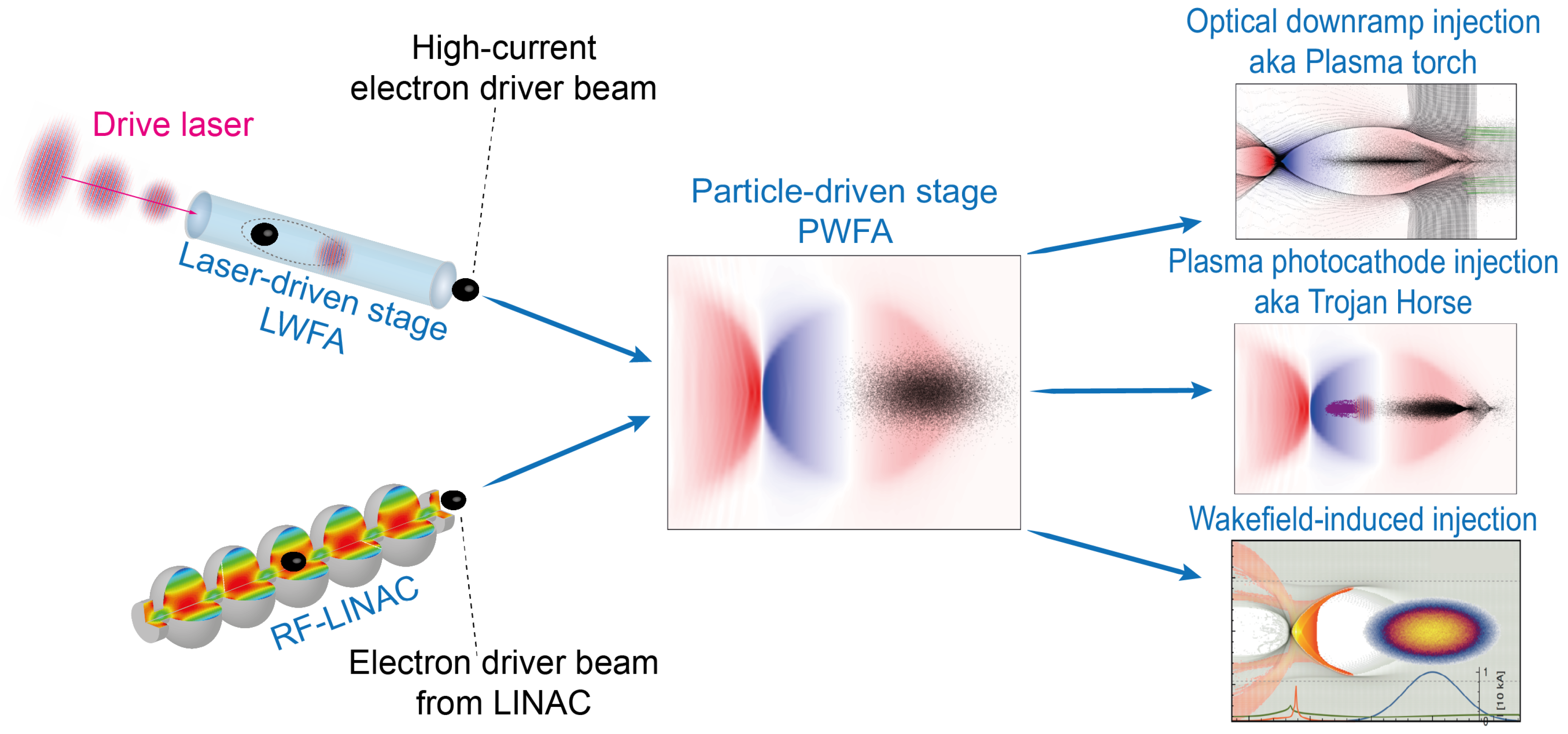
23]. These methods allow boosting the quality of electron bunches by many orders of magnitude, and therefore may pave the way to high performance key applications, such as for hard X-ray light sources or for potential building blocks for high energy physics research.
Figure 8 summarizes various options of injection on the right hand side. The central gateway building block here is PWFA, either driven by electron beams from linacs, or from LWFA.
In the following, the three injection methods are discussed briefly. In addition to the general idea of utilizing LWFA-generated bunches for PWFA, these are currently explored in the Strathclyde/DESY-led Work Package 14: “Hybrid Laser-electron-beam driven acceleration” of EuPRAXIA, the EU H2020 design study for a European Plasma Research Accelerator with eXcellence In Applications (2015–2019). Hybrid LWFA-PWFA and the Trojan Horse method, specifically, has been supported by RadiaBeam Technology’s US DOE-funded “Plasma Photocathode Beam Brightness Transformer for Laser-Plasma Wakefield Accelerators” (2013–2016) in a Strathclyde–RadiaBeam–UCLA-centered collaboration. Here, the work was broken down into the plasma photocathode research on the one hand, which was developed within the “E210: Trojan Horse PWFA” experimental programme (2012–2017) at the SLAC FACET linac, and R&D on the exploitation of LWFA-generated electron bunches for PWFA on the other hand.
Figure 8 visualizes the underlying conceptual approaches. A high-current electron beam, either coming from a linac, or from an LWFA stage, drives a PWFA stage, in which ionization injection based methods may generate electron beams of superior brightness, boosted energy, etc. These approaches are more complex when compared to single-stage LWFA, as well as linac-driven PWFA. However, they offer both compactness and high quality output beams, and are increasingly seen as pathway towards substantially higher beam quality from lab-scale accelerators as an alternative to conventional methods of bunch generation, which have limits that arise from fundamental principles. Schematically, one may draw a parallel to how many modern high power lasers operate: just as in state-of-the-art Ti:sapphire lasers green pump laser pulses are used to generate infrared laser pulses of much higher power and eventually, intensity, electron beams of already high density are used to generate electron bunches of much higher phase space density and brightness with the approaches sketched below.
2.1. Plasma Torch—All Optical Density Downramp Injection
Density downramp injection is an attractive method of bunch generation both for LWFA and PWFA, as it can realize localized and tunable injection of electrons into the plasma wave. It relies on a localized elongation of the plasma cavity on the plasma density downrampp, which facilities injection and trapping of plasma electrons into the plasma cavity. Density downramp injection is a state-of-the-art injection method for LWFA, where modern implementations even allow increasingly stable generation even of double bunches [
24], which could be used, e.g., for electron energy afterburners [
4]. While the use of a sharp density downramp for localized injection had been first suggested for PWFA [
25], it has not been realized for PWFA until recently in context of the E210 collaboration at SLAC FACET (to be published). One reason for this is the much poorer availability of PWFA driver beams when compared to high-power laser pulses for LWFA. Another one is the higher Lorentz factor
of electron beam driven plasma waves compared to LWFA, which increases the threshold of injection as pointed out above, and a further one is the general practical complexity and difficulty when generating downramps hydrodynamically, in particular in multi-component gas mixtures. However, in such multi-component mixtures with gases with lower and higher ionization thresholds, or in PWFA which relies on self-ionization of the supporting gas/plasma medium, plasma downramps can be generated optically, as suggested in [
23,
26]. In this approach, the plasma density spike and downramp are generated by an additional laser pulse, which generates plasma in the path of the electron beam driver by tunneling ionization of a gas component with higher ionization threshold. For example, in a hydrogen–helium gas mixture, preionized hydrogen can be used to support the wakefield, and helium with its substantially higher ionization threshold is ionized by a laser pulse which generates a plasma column or “plasma torch” perpendicular to the driver electron beam path on top of the preionized hydrogen.
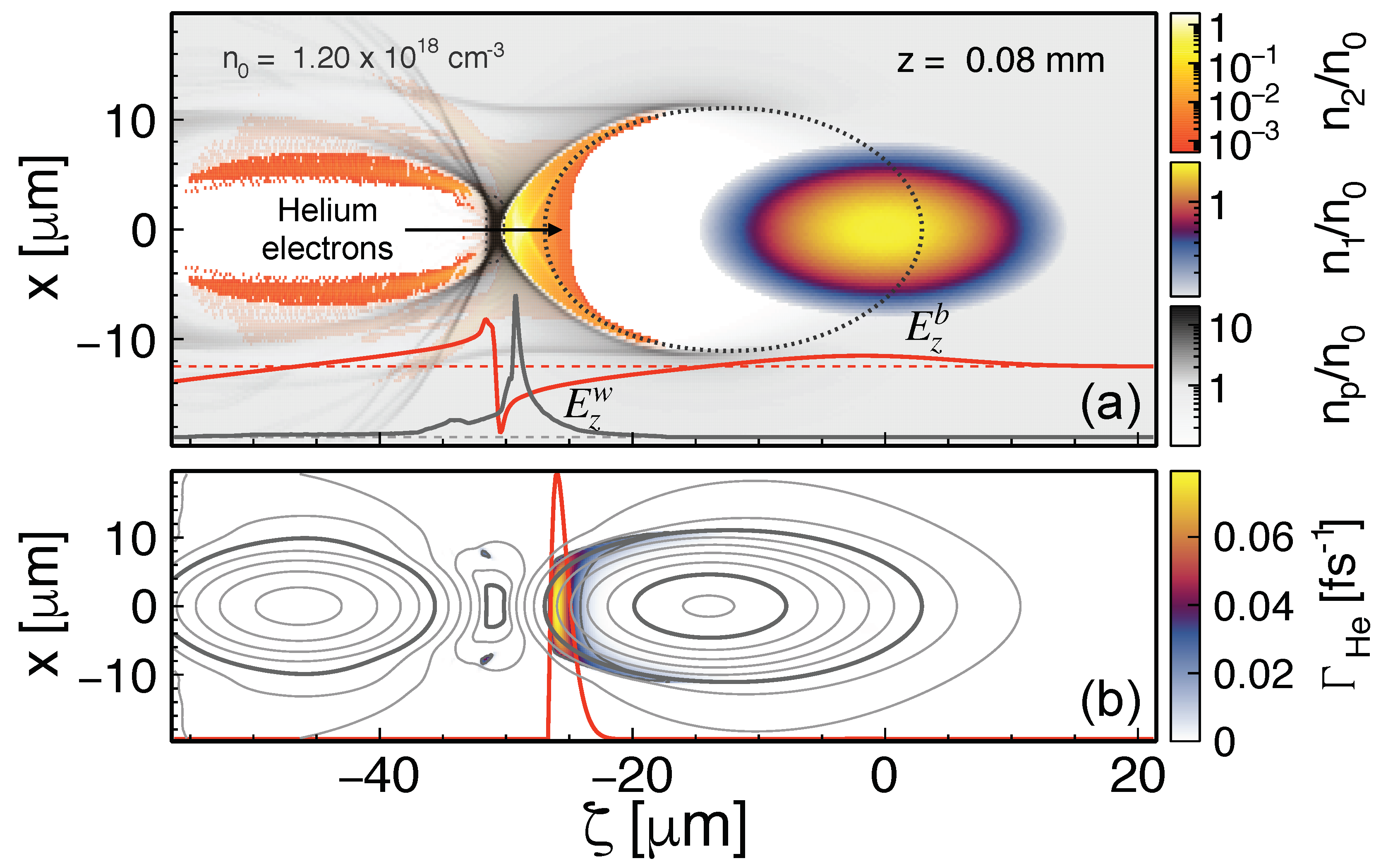
Figure 9 visualizes this approach by particle-in-cell simulations with the code VSim. The electron beam driver (black) propagates to the right through a hydrogen plasma channel, and encounters a perpendicular helium plasma torch (grey black). This plasma torch constitutes sharp local plasma density up- and downramps, and, when the electron beam driver arrives, this leads to a local distortion of the plasma wave such that plasma electrons are robustly injected at the desired position in the laboratory frame. Tuning of the laser pulse parameters and helium density allows exploring and optimizing [
27] this all-optically-triggered plasma downramp injection in a wide parameter range, including the production of high-brightness electron witness beams.
Owing to the extremely steep density downramp gradients, which this method allows to produce, injection can be achieved with comparably low driver beam currents of the order of 1 kA. Timing of the plasma torch injection method is uncritical, because the plasma torch filament, being generated by a laser pulse just above the ionization threshold, is rather cold and does not change much over a wide timing window of at least tens of ps, ultimately until recombination sets in. It is important to emphasize that the laser pulse required to generate the optical density spike can be of sub-mJ class for typical pulse durations of tens of femtoseconds, as the intensity required to tunnel ionize even helium sufficiently, the element with highest (first) ionization threshold, for Ti:sapphire lasers amounts to few . At these intensities and corresponding power levels, laser pulses are far more manageable than those with relativistic intensities such as required for LWFA. The feasibility of this approach is therefore very high, and as regards laser pulse management substantially less demanding than, e.g., double laser pulse and/or staged LWFA approaches. The required laser pulse powers to generate suitable plasma torches is even borderline within reach of fibre or thin disc laser systems. Shaping of the transverse laser pulse intensity profile, in combination with large tunability of the gas ratio, allows to produce plasma density spikes and downramps in a wide parameter range, including also very high charge beams, and with possibly very high stability. As with conventional downramp injection methods, the injected electron beam population is automatically produced on axis and therefore automatically aligned with the driver beam, which is an advantage of this injection method. As with other downramp injection methods, the injection rate is not only dependent on the shape of the downramp, but also on the strength and shape of the driver pulse and the corresponding wakefield strength and blowout sheath trajectories, which may vary from shot-to-shot in particular when using electron output from LWFA as drivers, which at present shows substantial shot-to-shot variations. This coupling is a disadvantage of this otherwise highly doable and attractive method. A first realization of this method—and at the same time the first realization of any downramp injection scheme in PWFA—has been achieved during the E210 programme at SLAC FACET (to be published). Once the necessary infrastructure was installed, the plasma torch downramp injection could be established within few days of beamtime in a reliable manner, which confirms the expectation of high feasibility of this method as implied by theory.
2.2. Trojan Horse—Plasma Photocathode Injection
The Trojan Horse [
28], also known as plasma photocathode injection method, is related to plasma torch injection. However, here the laser pulse needs to arrive very shortly after the electron beam driver, such that additional electrons via ionization of the higher ionization threshold medium are released approximately in the center of the blowout. Then, these electrons, which initially have negligible residual momentum due to the low laser intensity, are then rapidly accelerated in the forward direction by the plasma wakefield, which allows realizing particularly low emittance values. This can be achieved in various geometries between driver electron beam and release laser [
20], e.g., in perpendicular or collinear geometry [
21].
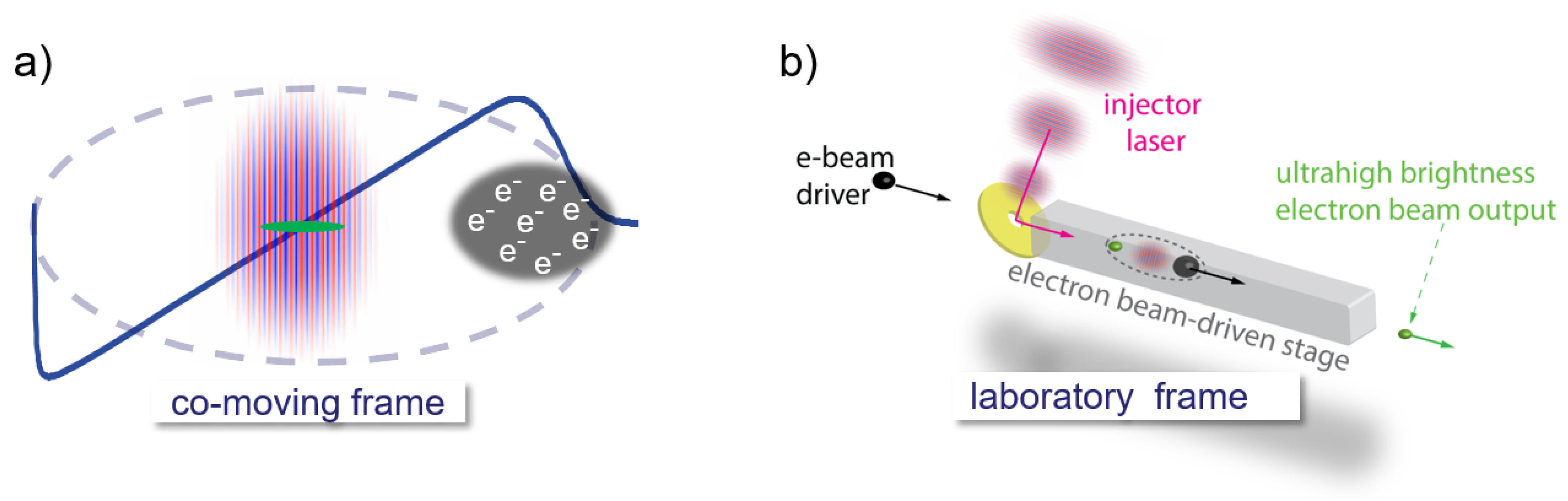
Figure 10 visualizes for collinear geometry how the process works in co-moving (left) frame and laboratory frame (right). The laser pulse focuses to intensities exceeding the ionization threshold of the higher ionization threshold medium (e.g., helium) in the center of the electron beam driven blowout, and releases helium electrons, represented by the green ellipse, at arbitrary position within the blowout. The center of the blowout is particularly interesting, because here the longitudinal wakefield is zero and the corresponding trapping potential is maximized: electrons released here harness the full accelerating field of the wakefield, which optimizes the use of the driver-excited wakefield for trapping. It is also an ideal position because here, longitudinal and transverse plasma wakefields are zero, and hence the laser-controlled release rate of helium electrons is completely decoupled from the wakefield excitation process. The witness bunch generation is therefore much more decoupled from drive beam jitter than in other schemes. One can also release with transverse longitudinal offset at other positions within the blowout, simply by shifting the release laser pulse with respect to the wakefield center. If one releases farther away from the center, however, transverse and longitudinal plasma wakefields may have to be taken into account for the tunneling ionization rates as superposition of laser and plasma wakefields. Because the trapping potential parabolic shape is flat at its maximum in the middle of the blowout, this position is also robust against longitudinal (i.e., timing) jitter of the release laser pulse. This may be important in context of linac-driven Trojan Horse, where there is no intrinsic synchronization between electron and laser beam. Finally, the center blowout position is also favourable because it allows to realize a robust dark-current free PWFA, when the trapping region is confined to the area around the center of the blowout [
29].
The plasma photocathode therefore allows uniquely tunable electron bunch generation. As regards obtainable beam quality, the key advantage is that the release laser pulse requires intensities just above the ionization threshold of comparably low ionization levels. In practice, e.g., a Ti:sapphire laser pulse at an intensity of
is sufficient to liberate electrons from helium, similar as for plasma torch injection. The ponderomotive force of such a laser pulse is comparably low, which in turn means that the residual transverse momentum of the released electrons is low—the released electrons are not transversally pushed out by the laser pulse, but simply remain on axis, fall back and catch up with the plasma wave. This is in contrast to LWFA, where the laser pulse
has to be intense enough to expel electrons off axis, and to excite the plasma wave. The low residual transverse momentum of electrons released by the plasma photocathode process is crucial, because it means the thermal emittance of produced electrons is very small [
21,
30].
The release laser can in principle be realized at arbitrary frequency [
20,
28], e.g., frequency-multiplied. This could be useful because then the electric field
which is needed for tunneling ionization is reached at a lower laser intensity, due to the
scaling with the normalized light amplitude
. Therefore, if operating at frequency-doubled laser light, i.e., at
nm,
can be decreased by a factor of 2, which further reduces the residual transverse momentum and thermal emittance contribution. The use of higher frequency light also has impact on the minimum obtainable spot size of a Gaussian laser pulse, and on the Rayleigh length, which has to be taken into account when calculating thermal emittance and phase mixing. However, at higher frequencies, multi-photon-ionization becomes relevant [
31], which may limit the range of applicability of shorter wavelength injector pulses, and of all-optical two-colour variations such as mentioned in [
32,
33] and explored in [
34]. The latter approaches have a different set of challenges and limitations, e.g., as regards dephasing (in particular for longer wavelength
driver pulses due to
) and diffraction of the driver beam, practical limitations in context of drive beam laser availability, tunability and parameter range, and may require gas-dynamic confinement of the high-ionization threshold component as in [
34].
Key advantages of the Trojan Horse method are:
The far-reaching decoupling of wakefield excitation from laser-based ionization injection with low-power laser pulses offers robustness and tunability, including use of different gas species for wakefield excitation and injection, respectively.
The unprecedented range of emittance and brightness of the obtainable electron beam: A key factor here is the residual transverse momentum of the released electrons, which means the (thermal) emittance scales with laser spot size and the normalized release laser amplitude
[
21,
30].
Because electrons can be released in the center of the blowout, a minimum drive beam current of 5–6 kA is sufficient to allow for trapping. Such currents are straightforwardly obtainable as output from LWFA systems. Such an LWFA-PWFA-TH system constitutes a triple-hybrid approach, as it would make use of the laser system for generating the electron beam driver in LWFA, for preionization of the PWFA stage, and for witness bunch generation.
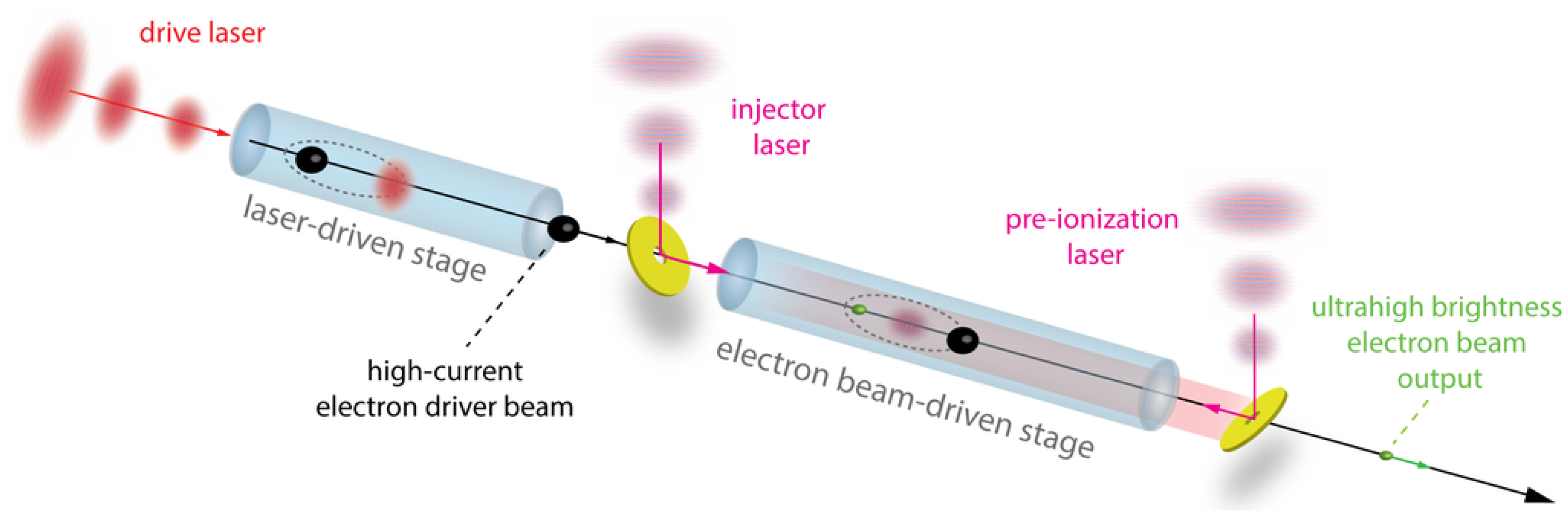
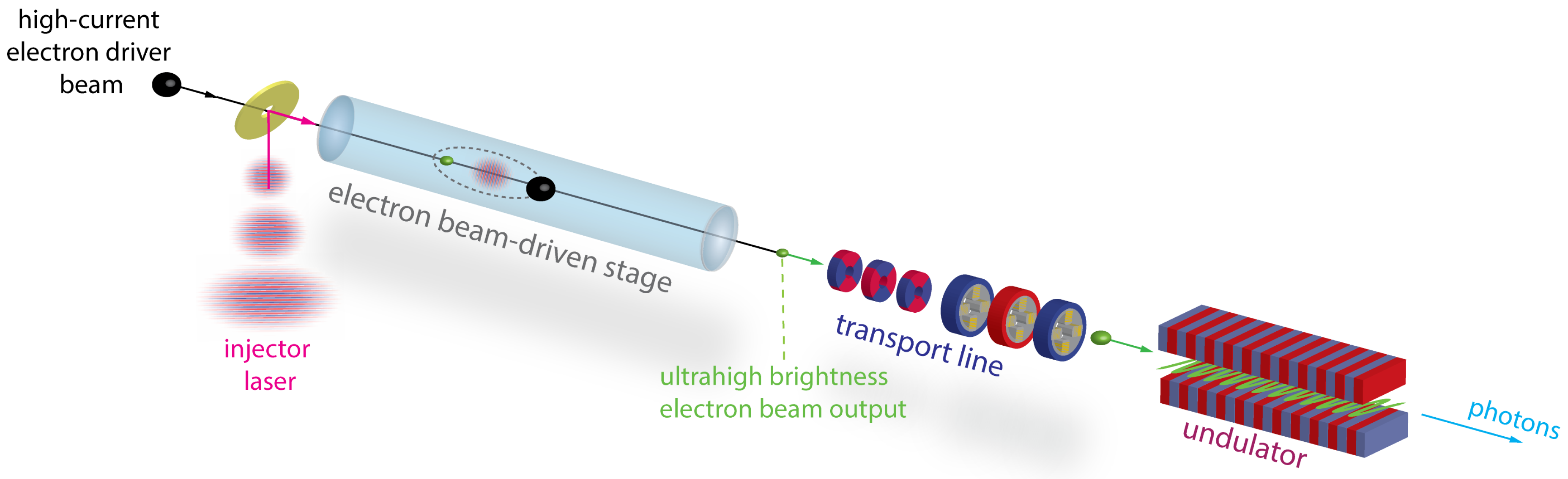
Figure 11 visualizes this potential setup. The preionization laser here is focused by an axilens and applied in counter-propagating geometry to allow a well-defined and wide plasma channel, and the plasma photocathode release laser has intrinsic synchronization with the electron drive beam—this hybrid setup therefore harnesses fully the advantages of being initially LWFA-driven.
Trojan Horse allows for tens of nm-rad scale normalized emittance values, kA-scale currents and hence in combination for unprecedented 5D-brightness. By employing tailored beam loading mechanisms [
17], the energy spread of the produced electron bunches can potentially be controlled and reduced to sub-0.01% values in one and the same plasma stage. This is important, as this reduces the challenges associated with extraction and transport of electron beams from the plasma stage and for beam quality and emittance preservation substantially. A low energy spread is also crucial for key applications, e.g., for photon science drivers.
It should be noted that the added level of complexity of hybrid LWFA-PWFA in various configurations when compared to, e.g., single-stage LWFA must not be confused with limited feasibility! On the contrary, the Trojan Horse scheme, which promises highest output beam quality and tunability, is composed such that the individual building blocks are all well controllable due to threshold effects: The preionization of the PWFA stage requires deploying laser pulse intensity sufficient to ionize the low ionization threshold component such as hydrogen, and excess intensity does not change the produced local plasma yield once 100% of the hydrogen is ionized. This acts as a bandpass filter against shot-to-shot laser intensity jitter.
Further, by operating at low plasma densities and hence large blowouts, the release position of electrons inside the blowout can be very stable and tunable: for example, for a blowout of
m size, the center of the blowout can be hit reliably with better than 1% stability shot-by-shot when assuming a plasma photocathode laser vs. electron driver beam time-of-arrival (and pointing) jitter of <30 fs. A sensitivity analysis of realistic timing, pointing and laser intensity jitter (to be published) confirms the expectation that near-constant charge bunches with tens of nmrad normalized emittance values and corresponding ultrahigh brightness values can stably be achieved shot-by-shot. When operating at such reduced plasma densities, the accelerating fields still amount to tens of GV/m, and next to injection stability the moderate fields are also advantageous because the reduced field gradient inside the blowout leads to a reduced residual energy spread [
17]. While
fs laser-electron beam timing stability can be reached at state-of-the-art linac-driven FEL facilities, using a split-off laser pulse from the LWFA system in the hybrid approach can assumedly be delivered with a synchronization stability at or better than the 1-fs level.
In the hybrid LWFA-PWFA variant, at present the major sources of shot-to-shot-jitter of the LWFA output are pointing, energy, energy spread, charge and current. However, energy spread and energy jitter is rather uncritical for any of the hybrid approaches for reasons discussed above, and as regards driver current jitter, the Trojan Horse scheme has unique advantages due to the injection process being to a large degree decoupled from a varying wakefield strength and shape shot-by-shot. Even if the drive beam current jitters substantially from shot-to-shot, and as a direct consequence the excited wakefield strength, the plasma photocathode-produced witness beam charge is completely independent from this, as it is only a function of the laser pulse and high-ionization-threshold medium (e.g., helium) density. Due to the parabolic shape of the trapping potential around the center of the blowout and the corresponding longitudinal electric wakefield, this laser-gated injection process has a further auto-stabilizing function even in case of drive beam shot-to-shot jitter. The approach therefore combines prospects for highest beam quality with ultrahigh tunability as well as potentially very high stability compared to other plasma wakefield approaches. The first demonstration of (linac-driven) Trojan Horse could be realized at SLAC FACET in the E210 programme, using plasma torch injection as a stepping stone (to be published). This was realized under boundary conditions of incoming beam jitter as well as blowout size which have been rather unfavourable and will be much improved e.g., for SLAC FACET-II, which confirms and fosters expectations as regards controllability and impact of this method in the future.
2.3. Wakefield-Induced Ionization—WII
The wakefield-induced ionization (WII) injection method [
22] exploits PWFAs operating at a high transformer ratio in order to induce ionization and trapping of high-quality electron bunches from and into the extreme accelerating fields of the plasma wake. These electrons originate from wakefield-induced ionization over an atomic species with appropriate ionization threshold, which is doped into the background plasma in a short axial region of the plasma target.
Electrons from the dopant species not only need to be ionized by the accelerating wakefields, but they also need to be trapped by the wakefields before they reach the end of the blowout cavity. This establishes a necessary condition for trapping which can be expressed in terms of the difference in wakefield potential between the initial and final phase positions of the electrons within the plasma wake [
35], i.e.,
, where
is the normalized wakefield potential, related to the longitudinal wakefields by
. Thus, the generated wakefields must be strong enough to generate a maximum difference in
greater than one. This imposes a constraint on the peak current of the drive beam, which needs to be at least
. This is a fundamental limit on the current of the drive beam required to generate a wakefield capable of trapping electrons originated from ionization [
36].
In particular for WII injection, the drive beams need an even higher peak current (around
or higher), in order to generate a stronger wakefield capable of trapping within a shorter phase range. However, high-current drive beams could also induce ionization over the dopant species by means of its space charge fields, if they are narrow enough. Therefore, in order to avoid ionization from the fields of the beam, it is necessary to start the WII injection process with a relatively wide drive beam. In this way, the trapped electrons will be originated by WII only, thereby constraining the final phase-space volume occupied by the witness beam, and, consequently, increasing its final quality. Remarkably, starting the plasma-wakefield generation process with a relatively wide drive beam also allows for largely improved stability of the PWFA system [
37].
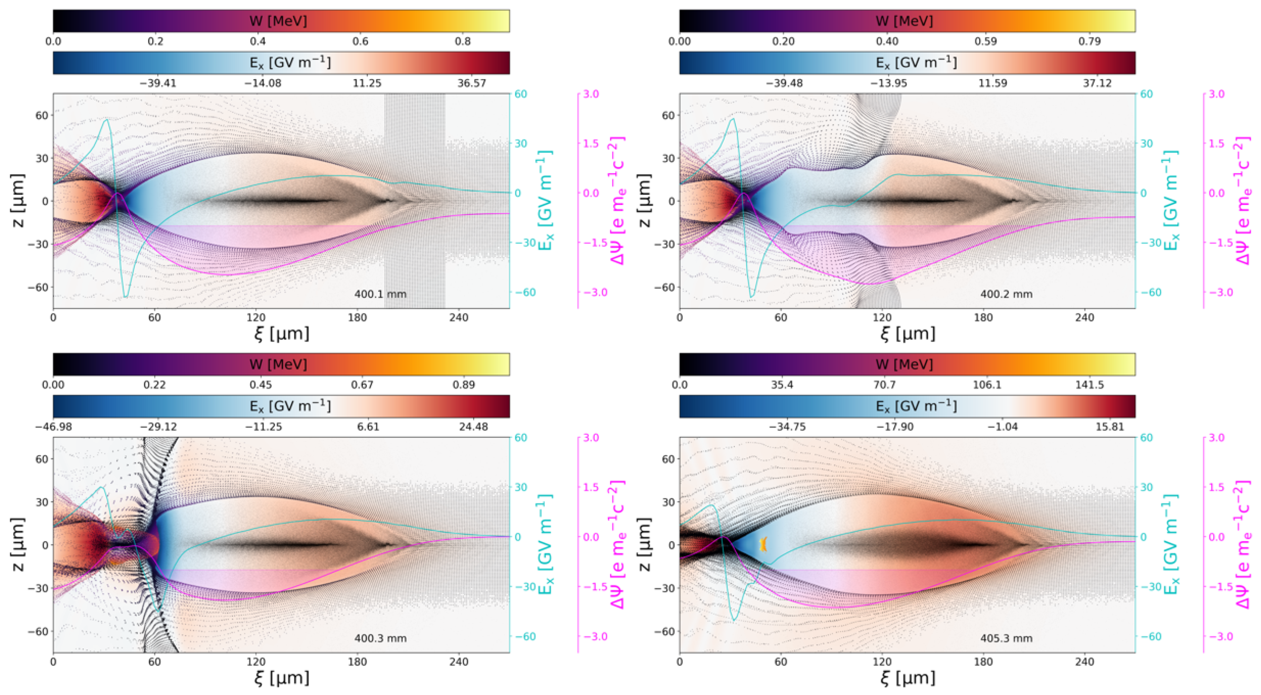
Figure 12 shows an example of WII injection performed with the PIC code OSIRIS [
38] in 3D Cartesian geometry, and considering a drive beam with similar parameters to those attainable in the FLASHForward experiment [
36]. In the simulation, a Gaussian drive beam with a peak current of
, a longitudinal (rms) size of
, a transverse (rms) size of
is initialized with an average energy of
. The total charge of the beam is
. In
Figure 12, the drive beam is traversing a homogeneous plasma at the resonant density
. The plasma is doped with neutral helium at
concentration. Near the end of the blowout cavity the accelerating wakefields are high enough to ionize completely the first electronic level of helium (
Figure 12b). From the total phase-space volume of ionized electrons, only the ones closer to the axis can be trapped within the blowout, provided that a difference in potential
can be asymptotically reached at the same time that the acquired transverse oscillation amplitude is smaller than the radial extent of the blowout at the final phase position
. This constrains the initial phase-space volume of the trapped electrons to a thin disc centered on axis which extends up to a radial position
. An upper estimate of the normalized transverse emittance of the so-injected witness bunch can be given in terms of the initial transverse extent of this disc
[
39], i.e.,
[
36]. Since typically
is smaller than one, a practical rule of thumb to scale the final normalized emittance of the WII-injected witness beams as a function of the plasma density can be given as
.
WII injection also allows for beam-loading optimization [
40]. The magnitude of the current profile of the injected beams can be controlled by adjusting the concentration of the dopant species in a similar fashion to how it is done in LWFAs with ionization injection [
12]. The magnitude of the current profile required for a minimal time correlated energy spread along the witness bunch is higher for higher transformer ratio cases [
36]. Therefore, since WII injection requires of a high-transformer ratio by design, the witness beams needs a high current (few tens of kiloamps) for an optimal beam-loading, and, consequently, for a low correlated energy spread [
36].
In summary, WII injection allows for the production of high current, low energy spread and low emittance electron beams, which can be accelerated to double or thrice the initial energy of the drive beam, all in a conceptually particularly simple setup.
Utilizing LWFA-generated electron beams to perform a PWFA with WII injection has unique advantages:
Electron beams from LWFAs can be of high current, reaching peaks of around
and beyond [
12]. Thus, they fulfill the essential requirement to enable WII injection in the PWFA stage. Other typical features of LWFA beams such as a ∼10% relative energy spread or a relatively high normalized emittance of ∼5
m are even beneficial to use them as drivers, given the enhanced stabilization that they provide to the PWFA system [
9,
37].
WII injection is triggered by the wakefields themselves, and therefore, there is no need for a precise time synchronization of external components, such as lasers, to enable injection. Moreover, the WII injection method is insensitive to the jittering of the pointing angle of the electron beam emerging from the previous LWFA.
Electron beams from LWFAs are typically of short duration, 10–20
[
12]. This means that the corresponding resonant density reaches values near
. At these densities the produced witness beams feature normalized emittances values below
and sub-fs duration.
It is best for the performance of WII injection to have relatively wide drive beams entering the plasma stage in order to avoid injection from the drive beam fields and to provide improved stability [
37]. This means that LWFA to PWFA staging with WII injection can tolerate a certain drift in vacuum of the highly divergent electron beam from LWFA. This simplifies the LWFA to PWFA setup as there is potentially no need of beam optics between stages to transport and refocus the LWFA beam into the PWFA stage.

 ,
, 


