Article

Skew Quadrupole Effect of Laser Plasma Electron Beam Transport

by
Driss Oumbarek Espinos
1,2,3,
Amin Ghaith
1,3,
Thomas André
1,
Charles Kitégi
1,
Mourad Sebdaoui
1,
Alexandre Loulergue
1,
Fabrice Marteau
1,
Frédéric Blache
1,
Mathieu Valléau
1,
Marie Labat
1,
Alain Lestrade
1,
Eléonore Roussel
4,
Cédric Thaury
5,
Sébastien Corde
5,
Guillaume Lambert
5,
Olena Kononenko
5,
Jean-Philippe Goddet
5,
Amar Tafzi
5,
Victor Malka
5,6 and
Marie-Emmanuelle Couprie
1,*
1
Synchrotron SOLEIL, Saint-Aubin, 91192 Gif-sur-Yvette, France
2
Graduate School of Engineering, Osaka University, 2-8 Yamadaoka, Suita, Osaka 565-0871, Japan
3
Université Paris-Saclay, Doctoral School PHENIICS, 91190 Paris, France
4
CNRS, UMR 8523, PhLAM—Physique des Lasers Atomes et Molécules, Université Lille, F-59000 Lille, France
5
LOA, Ecole Polytechnique, ENSTA ParisTech, CNRS, Université Paris-Saclay, 826 Bd des Maréchaux, 91762 Palaiseau CEDEX, France
6
Departement of Physics of Complex Systems, Weizmann Institute of Science, Rehovot 761001, Israel
*
Author to whom correspondence should be addressed.
Appl. Sci. 2019, 9(12), 2447; https://doi.org/10.3390/app9122447
Submission received: 6 February 2019 / Revised: 27 May 2019 / Accepted: 10 June 2019 / Published: 14 June 2019
(This article belongs to the Special Issue Laser-Driven Particle Acceleration)

Abstract

:
Laser plasma acceleration (LPA) capable of providing femtosecond and GeV electron beams in cm scale distances brings a high interest for different applications, such as free electron laser and future colliders. Nevertheless, LPA high divergence and energy spread require an initial strong focus to mitigate the chromatic effects. The reliability, in particular with the pointing fluctuations, sets a real challenge for the control of the dispersion along the electron beam transport. We examine here how the magnetic defects of the first strong quadrupoles, in particular, the skew terms, can affect the brightness of the transported electron beam, in the case of the COXINEL transport line, designed for manipulating the electron beam properties for a free electron laser application. We also show that the higher the initial beam divergence, the larger the degradation. Experimentally, after having implemented a beam pointing alignment compensation method enabling us to adjust the position and dispersion independently, we demonstrate that the presence of non-negligible skew quadrupolar components induces a transversal spread and tilt of the beam, leading to an emittance growth and brightness reduction. We are able to reproduce the measurements with beam transport simulations using the measured electron beam parameters.

1. Introduction

In laser plasma acceleration (LPA) [1], an ultra short laser pulse generates a plasma wave with relativistic phase velocity arising from the ponderomotive force of the pulse. Particles can be accelerated with electric fields up to three orders of magnitude (>100 GeV/m) [2] larger than conventional radio frequency accelerators, motivating the development of shorter accelerators for high energy physics and light source applications. Along with the high power laser development thanks to chirped pulse amplification [3], significant electron beam acceleration was achieved [4,5,6,7,8] at the beginning of this century. LPA can provide accelerating gradients from a few hundreds of MeV to several GeV per cm and reasonable beam characteristics (typical current of a few kiloamperes, relative energy spread of the order of 1 % , and a normalized emittance of the order of 1 π mm mrad) [9,10,11,12,13,14,15,16,17,18,19,20,21]. However, all these “best” performances are usually not achieved simultaneously and depend on the chosen configuration. Different methods have been proposed to control the plasma wave and electrons injection. The colliding pulse regime [9,22] high-quality electron bunch with low energy spread can have tuneable energy by changing the laser collision position. Density ramp injection [23] generates well-collimated, short electron bunches with narrow energy spread. Ionization injection [24,25,26], with a simple and robust setup and a stable injection mechanism, allows for stable performance over multiple hours of operation, as well as easy tuning of beam parameters through modification of the gas characteristics.
LPA, now capable of generating electron beams of several GeV [19,27], with fs duration [12], excellent emittance at the plasma-vacuum interface (∼1 mm mrad), and high peak current (1–10 kA) within the cm scale, drives a large interest for different applications such as future colliders [28], light sources (undulator radiation [29], and free electron laser (FEL) [30,31,32,33,34,35]). LPA has to move from the new acceleration concept to prove that the devices can be operated as an accelerator. For such a purpose, the electron beam along a transport line has to be controlled. Specific requirements appear for different applications. For example, the collider application requires being able to stage LPA accelerators, but so far, the energy step is still limited [36,37] since the transport between the different stages is very challenging. The feasibility of observation of undulator radiation was demonstrated [38,39,40,41] after a first electron beam strong focus, but without evidencing the full properties as currently achieved on the synchrotron radiation light source, which would make it attractive for user applications. For the FEL application, proper beam parameters should be provided in the undulator for the amplification to be possible, requiring a specific phase space manipulation.
The application of conventional accelerator techniques for the transport are not straightforward in the LPA case. The characteristics of the beams in longitudinal and transverse phase spaces are very different. In the longitudinal phase space, whereas the conventional accelerators typically operate at ultra-low energy spread, the LPA exhibits ultra-short electron bunches that are likely to be lengthened along the transport. In the transverse phase space, the LPA appears as a diverging (mrad) point source, whereas the conventional accelerator operates with typically 10–100 μ m divergence. Consequently, the chromatic effects associated with the divergence and the energy spread, which are generally negligible on conventional accelerators, appear to play a major role and complicate the transport, where a significant emittance growth can occur [42,43,44,45]. Strategies are proposed to mitigate this, such as an adiabatic matching section [46], tailoring focusing profiles [47] or creating a decreasing plasma gradient after the source [48]. Another robust approach consists of capturing the electron beam right after the source via strong focusing magnetic fields as close as possible to the plasma–vacuum interface with conventional accelerator techniques (e.g., the use of FODO with quadrupoles) [34,49,50]. The required gradient in a compact device is challenging. Plasma lenses (APL) [51,52,53,54] are promising [55], but their use in experiments that run for couple of weeks adds an additional level of risk. Because of the expertise gained in accelerator facilities, the use of permanent magnet quadrupoles (PMQs) appears to be slightly more robust in respect of APL. The required gradient level corresponds to values achieved for prototype systems [49,56,57,58,59,60,61,62,63,64,65,66,67,68] rather than quadrupoles produced in large amounts. Moreover, special care has to be taken for the design of these PMQs, in particular for their multipolar content in order to minimize the beam spot size while avoiding chromatic aberration effects dominance [56,69]. As compared to a single pass conventional accelerator, the situation gets more complex due to the combination of chromatic effects and multipoles. In addition, reliability, in particular with the pointing fluctuations, sets a real challenge for the control of the dispersion along the electron beam transport, and there are still very few experiments reporting on a controlled LPA beam transport. A transport preserving the source electron beam properties all along a line has not yet been achieved. A first approach to controlling the electron beam along a transport line downstream to an undulator on the COXINEL line [41] was enabled thanks to a beam pointing alignment strategy, enabling us to separately adjust the beam dispersion and position.
In this paper, we investigate how the skew components of the first high gradient quadrupoles required to tackle with chromatic effects can affect the brightness of the transported electron beam with electron beam simulations in the case of the COXINEL line. We examine how the electron beam dynamics is distorted when a skew component is added. We show that the higher the initial beam divergence, the larger the degradation. Experimentally, under conditions of proper electron beam transport, we evidence that non-negligible skew quadrupolar components induce a transversal spread and tilt of the beam, leading to an emittance growth and brightness reduction. We also reproduce the measurements with beam transport simulations using the measured electron beam parameters.

2. Emittance Growth Issues on LPA

2.1. Theoretical Approach

The peak brightness [70], a proper figure of merit for most LPA based applications, is defined as:
B = 2 I π 2 ϵ g , z ϵ g , x ,
where the peak current I and the beam transverse geometrical emittance ϵ g , z and ϵ g , x appear as key characteristics. Calculating the propagation on a simple model composed of a drift of length L, followed by a quadrupole of strength k = 1 / L to compensate the divergence, and tilted by θ , gives for the emittance:
ϵ g , x 2 ϵ g , x , i 2 + 4 θ 2 σ x , i 2 σ z , i 2 L 2 + L 2 σ x , i 4 σ γ 2 ,
where ϵ g , x , i 2 = ( < x 2 > < x 2 > < x x > 2 ) [42] is the initial emittance and σ x , i , σ z , i and σ γ the horizontal and vertical divergence and energy spread, respectively. The second and third term are the tilt and chromatic [71] emittance, respectively, both largely amplified by the beam divergence. For θ , σ x , i , σ z , i = 1 mrad, σ γ = 1%, ϵ g , x , i = 0.2 mm.mrad, and L = 200 mm, the usual distance between source and the quadrupole, the tilt term gives a value of 0.14 mm.mrad and the chromatic term 0.7 mm.mrad, which shows the how these two terms dominate the emittance evolution for mrad divergences.We define the normalized emittance, which is most commonly used, as the emittance normalized by the mean relativistic factor < γ > according to relation 15 in [42].

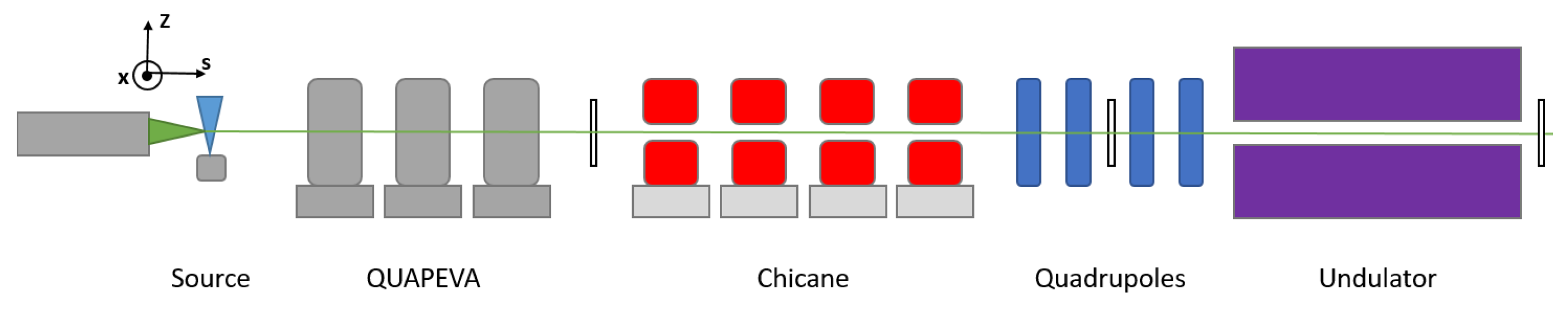
2.2. Experimental Test Bench: The COXINEL Line

The influence of the skew components of the first quadrupoles was tested on the LPA-based COXINEL line [67,72,73,74], designed for FEL. For such a purpose, the relative energy spread (RMS) σ γ over one coherent length should be less than σ γ < ρ , with ρ as the Pierce parameter [75]. This requirement becomes an issue since relative energy spreads of percentage level have been measured for LPA beams [13], so until more improvements are made in LPA systems, these beams have to be first modified to satisfy the FEL condition and transported to the undulator. Mitigations rely in decompressing the beam in a magnetic chicane [41,44,76,77,78] enabling us to reduce the slice energy spread to acceptable levels for FEL, or by using a transverse gradient undulator (TGU) [79,80] that generates a linear transverse dependence of the undulator field associated to dispersion, introducing a transverse displacement with the energy according to the undulator resonance condition for a particular undulator gradient. The TGU minimizes the energy spread effect, leading to an improvement of FEL gain and radiation power.
Figure 1 shows the sketch of the COXINEL line. Electrons were produced and accelerated by a Titanium:Sapphire laser focused on a gas jet. A triplet of permanent magnets quadrupoles with tunable gradient (QUAPEVA [57,58]) positioned 5 cm from the source handles the bit of mrad initial divergence of the electron beam via a strong magnetic field, insuring a proper beam focusing. Then, a demixing chicane consisting of four electro-magnetic dipoles accompanied with a removable and adjustable slit placed in the middle stretches the beam longitudinally, sorts electrons by energy, and then selects the energy of interest via the slit. A second set of four electromagnetic quadrupoles (EMQs) enables a beam to focus into a cryo-ready undulator of 107 periods. In addition, scintillating screens enable measuring the beam size and shape at different locations along the line [67]. The coordinate system shown in Figure 1 uses x as the horizontal direction, z as the vertical one, and s as the longitudinal one.
A laser system at “Salle Jaune” of Laboratoire d’optique Appliquée was used for the LPA source. The titanium:sapphire (Ti:Sa)-based laser system provides a linearly polarized light in the horizontal direction, 800 nm, 30 fs (FWHM), 30 TW pulse to the interaction chamber where it is focused into a spot of 20 μ m (FWHM) in a supersonic jet with a millimeter scale nozzle of gas mixture composed of 99% helium and 1% of nitrogen. LPA is operated in the ionization injection configuration for its robustness and relatively high charge. The electron beam generated by LPA is firstly characterized with a removable electron spectrometer, located at 355 mm from the gas jet. The spectrometer uses a permanent magnet dipole of 1.1 T field and 100 mm long to horizontally disperse the beam, a lanex screen, and a CCD camera with a spectral resolution of 2.7% and 3.8% between 50 MeV and 280 MeV. The electron beam is then monitored with a first beam imager positioned 64 cm from the LPA source and mounted on a motorized stage. The imager is composed of a lanex scintillating screen protected by a 75 μ m black ionized aluminum foil, a pair of lenses, and a CCD camera (scA640-70gm Basler scout with a resolution of 150 μ m). The ratio r = σ x σ z of the horizontal beam size σ x to the vertical one σ z measured on the imager is assumed to be equal to the horizontal to vertical divergence ratio. From the electron spectrometer, the vertical divergence is measured, and thus, the horizontal divergence. The COXINEL test experiment enables providing different values of the initial electron beam divergences and of the skew angle of the first strong focusing particles.

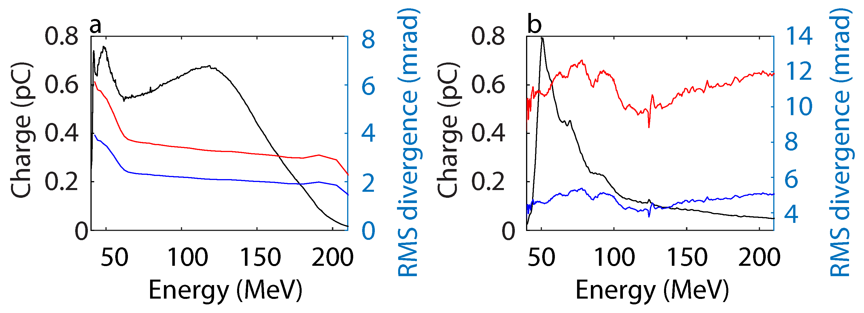
2.3. The Two Electron Beam Initial Conditions

Typical beams are generated in a 50–300 MeV range, with 1.5–5 mrad (RMS) vertical initial divergence. The total beam charge is up to 200 pC distributed over the entire electron energy range. However, the energy range of interest is 176 ± 0.1% MeV (corresponding to an inhomogeneous bandwidth inferior to the natural bandwidth of the first harmonic [81]) where only a small fraction of the charge is contained. Figure 2 presents the measured beam energy distribution and divergences: low (Figure 2a) and high divergence (Figure 2b). Both cases differ in terms of the initial vertical divergence (2 versus 5 mrad), divergence ratio (1.56 versus 2.35), and charge density (at the energy of interest close to 0.3 pC/MeV vs. 0.1 pC/MeV). Both energy distributions span over a broad range of energies, which translates into a huge energy spread. Thus, with the necessity of the chicane with a slit, the transport line is set up so the energy of interest 176 MeV is perfectly transported and most of the other energies will be cut at the slit. Consequently, most of the beam charge is lost, while the charge of 176 MeV will be transported. The shot-to-shot pointing variation on the first beam imager for the data set of Figure 2a is 2.62 mrad in the horizontal direction and 0.49 mrad in the vertical direction. ϵ x , i , ϵ z , i = 0.2 mm mrad and the initial bunch lentgh σ s , i = 1 μ m (Table 1) has been extracted from the LPA particle in cell (PIC) simulations of the source setup used.

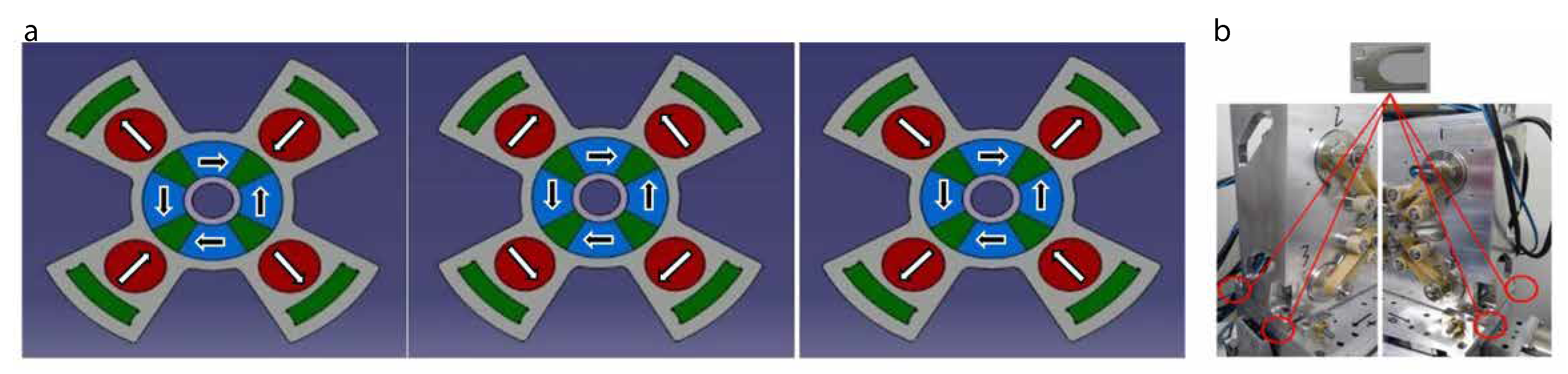
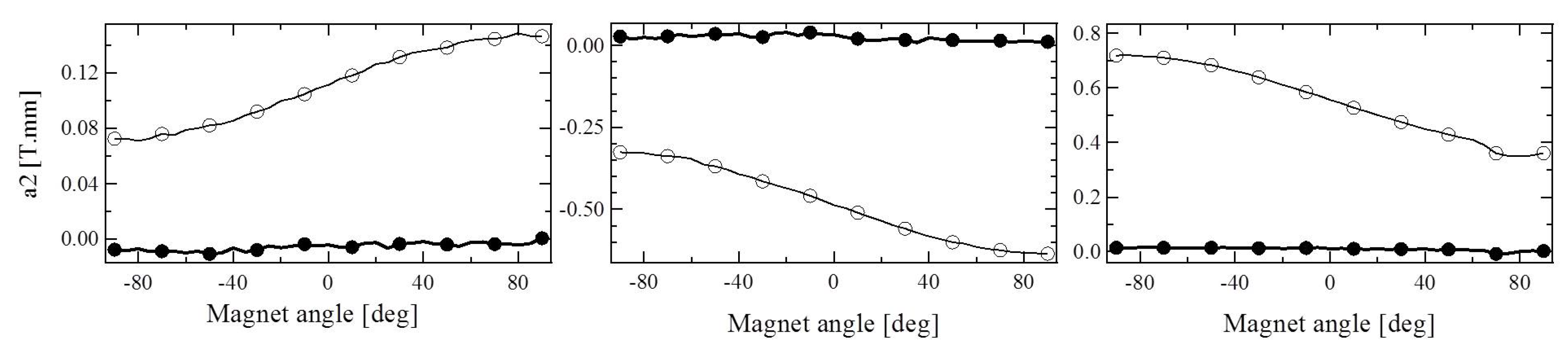
2.4. QUAPEVA: The Two Skew Quadrupolar Components Configurations of the First Strong Focusing Quadrupoles

The quadrupole local field is given by B ( c ) = n = 1 ( B n + i A n ) c n 1 r 0 n 1 [82], with n as the multipolar order, the complex number c = x + i z , B n the normal multipolar, A n the skew component, and r 0 the radius. The quadrupoles comport the desired normal terms ( B 2 ), and unwanted components such as skew contributions ( A 2 ) and higher order multipoles. Integrated components are defined as a n = A n · d l and b n = B n · d l , with l as the longitudinal direction. QUAPEVA is composed of two quadrupoles embedded in one mechanical structure [57] (see Figure 3): a first Halbach hybrid structure with four Nd 2 Fe 14 B permanent magnets (PM) (high remanence field (∼1.26 T) and coercivity (1830 kA/m)) and four iron–cobalt alloy magnetic poles, and a second one composed of four PM cylinders with a radial magnetic moment orientation, which produces a variable gradient by the rotation around their axis. Four Fe–Co alloys are placed behind the cylinders to shield the magnetic field and redirect the lines into the core. The magnetic system is built into a dedicated aluminum support frame in order to maintain the elements in their positions due to the strong generated magnetic force. This design guarantees a gradient higher than 100 T/m with a large tunability, i.e., greater than 30%, alongside small harmonic components ( b 6 / b 2 < 3%) for a bore radius of 6 mm, with magnetic lengths from 26 mm up to 100 mm to provide different integrated strengths. Because of the inherent uncertainty of the assembly process on the positions of the central Halbach ring, the QUAPEVA design is subject to the present default skew quadrupole contribution. After construction, the measured QUAPEVA multipolar terms using a stretched wire [83] (Table 2) present a non-negligible skew quadrupole contribution. The dodecapolar term ( b 6 ) relative to the main quadrupolar term ( b 2 ) is between 2% and 2.3% for the three QUAPEVAs. The QUAPEVA transverse magnetic center offset error is limited to ±10 μ m [57]. The skew real component a 2 can be characterized by an angle (see Table 2), defined as:
θ = 1 2 a r c t a n ( a 2 b 2 ) .
The skew quadrupole components, arising from the roll angle in the QUAPEVA, are corrected by introducing a small metallic plate (called shim) as thick as 500 μ m between the QUAPEVA and the base as shown in Figure 3b. The measured skew quadrupolar term a 2 for the triplet used at COXINEL has been reduced by more than a factor of 10 by compensating the roll angle (see Table 2, Figure 4).

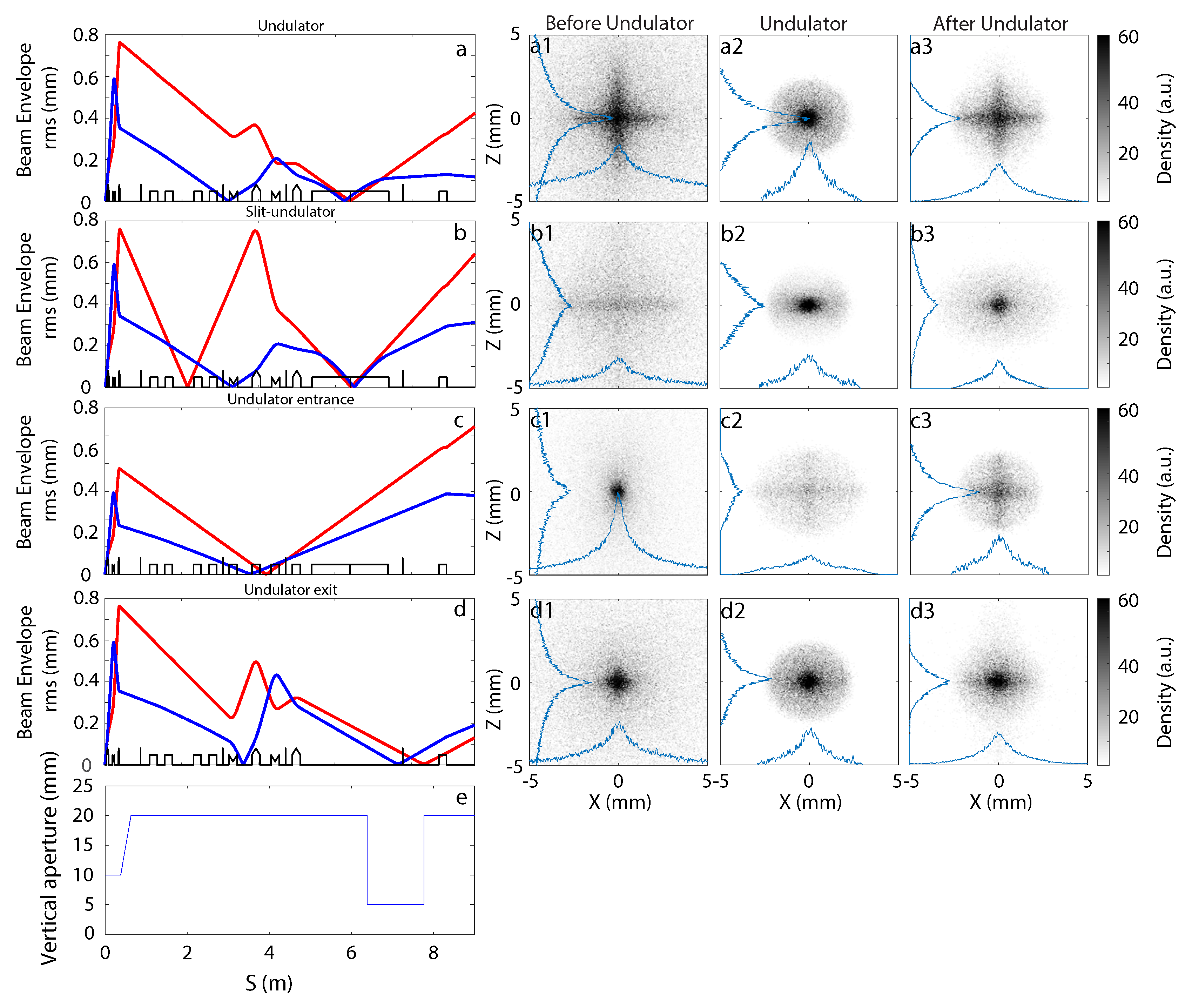
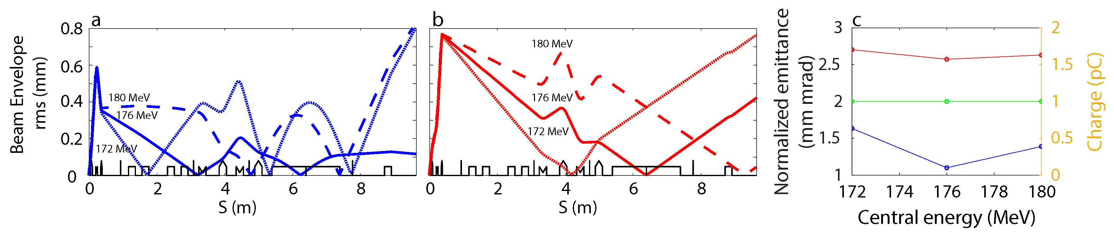
3. Electron Beam Transport for Ideal Magnetic Elements

The electron beam transport is modeled up to the second order with BETA [84], where using a multiparticle tracking code, based on sympletic mapping, the electron beam is tracked in a 6D phase space which describes position, momenta, and energy at any location along the line. The product of the different matrix elements of the line (drift, quadrupole, dipole, etc.) by a particle array gives the 6D phase space of the particle [72]. The code was benchmarked on COXINEL with ASTRA [73,85], ELEGANT [86], and OCELOT [87]. The distribution of electron charge versus energy and the vertical divergence per energy slice are extracted and used as initial beam parameters for the transport code. Transport simulations were tested with ϵ x , i , ϵ z , i = 0.5 mm.mrad and ϵ x , i , ϵ z , i = 1 mm.mrad, and the variations of the beam parameters are close to the simulations variations as well as for σ s , i = 0.5 μ m and σ s , i = 5 μ m.
Figure 5 shows the optics configurations (Figure 5a–d) and the associated beam transverse shape observed on the screen located at the entrance, center, and exit of the undulator (Figure 5a1–d3). The envelope is modeled using a 176 ± 0.3 MeV flat-top energy distribution electron beam with σ z , i = 2 mrad (RMS) and σ x , i = 3.12 mrad (RMS), while the transverse shape on the screens is simulated for the low divergence beam case (see Figure 2, Table 1) and the magnetic elements settings given in Table 3. In Figure 5a (“undulator” optics), the focus is set for both axes in the undulator, while in Figure 5b (“slit-undulator” optics), the beam is first focused horizontally onto a slit and then both vertically and horizontally focused on the undulator center. In Figure 5c (“undulator-entrance” optics), the focus is set onto the screen located at the undulator entrance (the associated transverse distribution exhibits a tiny spot there, while the beam size increases at the undulator exit). In Figure 5d (“undulator-exit” optics), the beam is well focused at the exit of the undulator. Figure 5e presents the vertical aperture along the trasport line: 10 mm in the QUAPEVAs, 20 mm in the vacuum pipe, 5 mm in the undulator.
Figure 6a,b presents the envelope evolution with the “Undulator” optics for a flat-top distribution for different energies: The nominal energy (176 MeV) electrons are focused at the center of the undulator, while the lower energy (172 MeV) (resp. higher energy (180 MeV)) ones are focused before (after) the undulator. The chromatic dependence induces a cross shape on the focus spot at the screen before and after the undulator (Figure 5a1,a3), due to the various energies being focused at different horizontal and vertical positions instead of the center of the undulator. Figure 6c shows the emittance and the charge at the undulator center for different energies. The emittance is minimum at 176 MeV, in which the optics has been designed. The vertical (horizontal) emittance increases by a factor of 1.5 (1.05) for 172 ± 0.3 MeV and by a factor of 1.26 (1.02) for 180 ± 0.3 MeV. No charge is lost in any of the three cases.

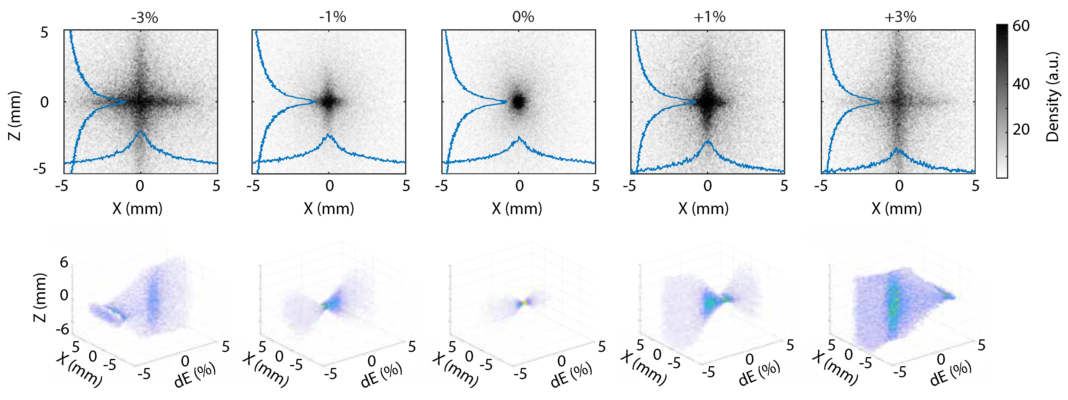
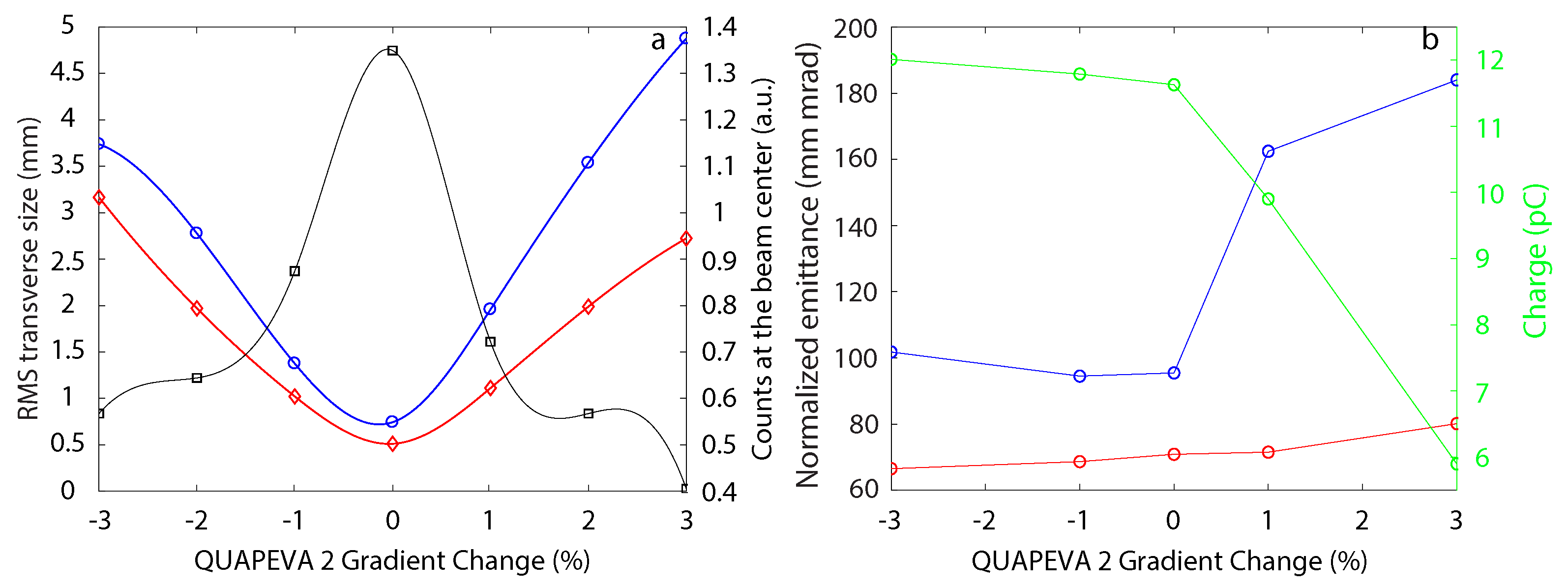
Beam Shape Dependence on QUAPEVA 2 Gradient

The influence of the gradient change of the strongest QUAPEVA (the second one) is investigated in Figure 7, where the evolution of the beam transverse distribution at the undulator entrance versus the QUAPEVA 2 gradient is presented for the “undulator-entrance” optics (see Figure 5c). For the reference setting gradient, the beam displays a vertically and horizontally focused spot on the screen, especially for the energies around 176 ± 1 MeV. For the larger gradient, the vertical–horizontal position per energy plot indicates that the high energies get vertically focused, while the central and lower energies are focused in the horizontal plane. In consequence, the pattern observed on the screen exhibits a cross shape. By decreasing the gradient, the opposite occurs, the lower energies being the ones focused vertically and the rest being focused horizontally as appreciated in the vertical–horizontal position per energy plot. The width and density in the cross arms are uneven due to the difference in electron density per energy (see Figure 2).
Figure 8a shows the maximum vertical and horizontal RMS beam sizes and the peak intensity at the center of the beam for the different gradients with the “undulator entrance” optics. When the beam is not properly focused (+1%), the beam size increases, and the intensity is reduced by a factor of two. Figure 8b presents the effectiveness of the transport at the undulator center versus QUAPEVA 2 gradient in the case of the “undulator” optics. When the gradient is reduced, the charge arriving at the center of the undulator is slightly increased because the lower energy electrons are focused on the horizontal plane avoiding the loss due to the vertical aperture of the undulator. When the gradient is increased by 3%, the charge is halved because of high energy electron loss (see Figure 2b) on the undulator vertical aperture (see Figure 5e). The horizontal emittance slightly changes from −3% to +3%, and the vertical one grows by a factor of 1.5 for the 1% case.

4. Effect of the QUAPEVA Skew and Initial Beam Conditions on the Electron Beam Transport

As observed in Equation (2), in a single quadrupole system, the second term which depends on the transverse divergence and the rotation of the quadrupole quickly dominates over ϵ g , i . The emittance behavior through the line in relation to the skew quadrupole component (angle) of the first QUAPEVA triplet and to the initial divergence σ x , i is here investigated at the undulator entrance and exit using the specific optics enabling us to focus the beam on those particular screens and the phase–space distribution of the beam.

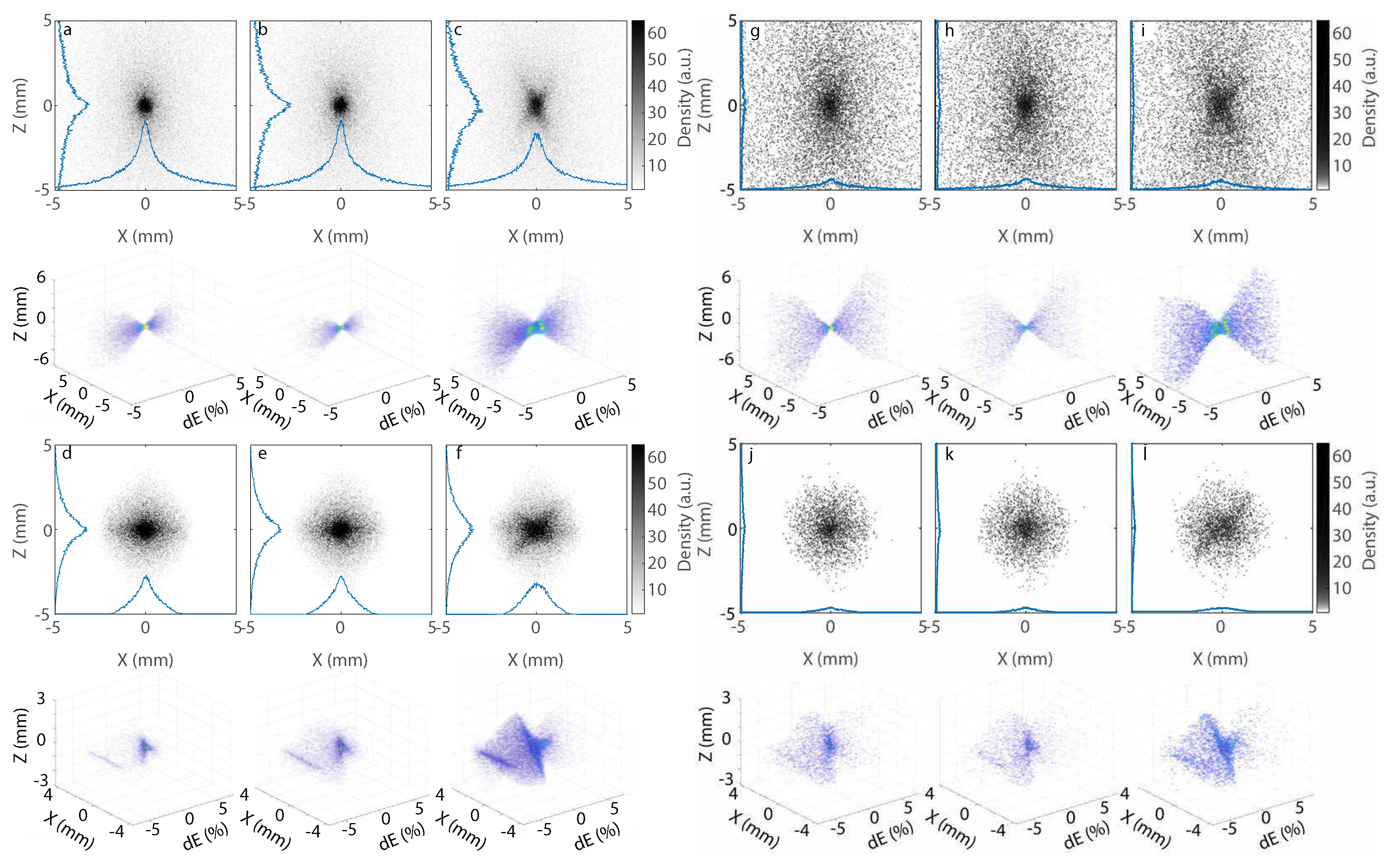
4.1. Variation of Skew Quadrupole Component

In the case of a low initial divergence electron beam (see Figure 2a, Table 1) for an ideal quadrupole ( a 2 = 0), the RMS beam size is 0.52 ± 0.02 mm and 0.80 ± 0.10 mm horizontallly and vertically, respectively (see Figure 9a). When a small skew quadrupole term (Table 2) is added (Figure 9b), the beam remains well centered and focused (RMS beam size of 0.52 ± 0.05 mm and 0.72 ± 0.08 mm horizontallly and vertically, respectively). For high a 2 (Table 2) (see Figure 9c), the beam exhibits a tilted cross shape, resulting from the change of gradient angle (see Equation (3)).
For a low value of a 2 , the beam size at the undulator entrance (see Table 4) is slightly smaller horizontally and larger vertically than for an ideal quadrupole ( a 2 = 0). A substantial decrease in intensity occurs when a 2 is enhanced to the high a 2 value at the undulator entrance. After the undulator, the intensity and beam sizes (Table 4) for null and low a 2 are close. Figure 9g–l presents simulations using an input beam with a divergence three times larger and smaller charge density for the energy of interest (high divergence beam case of Figure 2b and Table 1). For a 2 = 0 (see Figure 9g), the beam is well focused. For a slight increase of a 2 (Table 2), the beam remains similarly focused. A larger increase of a 2 (Table 2) (see Figure 9i) leads to a tilted cross. Figure 9j–l shows a reduction of intensity resulting from electron beam loss along the reduced vertical aperture. The transport becomes much less efficient for higher initial divergence. The corresponding intensities and beam sizes for the different cases are shown in Table 4. The beam size for larger a 2 at the undulator entrance is higher than in the low divergence case. However, the size is closer to those of the null and low a 2 cases at the undulator exit. For a low divergence beam, the intensity drops to 0.8 (0.5) at the screen before (after) the undulator for the high a 2 value. In the high divergence case, the highest intensity achieved is 0.2 (0.14) for the low (high) a 2 case and decreases until 0.14 (0.11) at the undulator exit. For a high divergence beam (see Figure 2), the charge arriving to the undulator is a small fraction of the initial one.

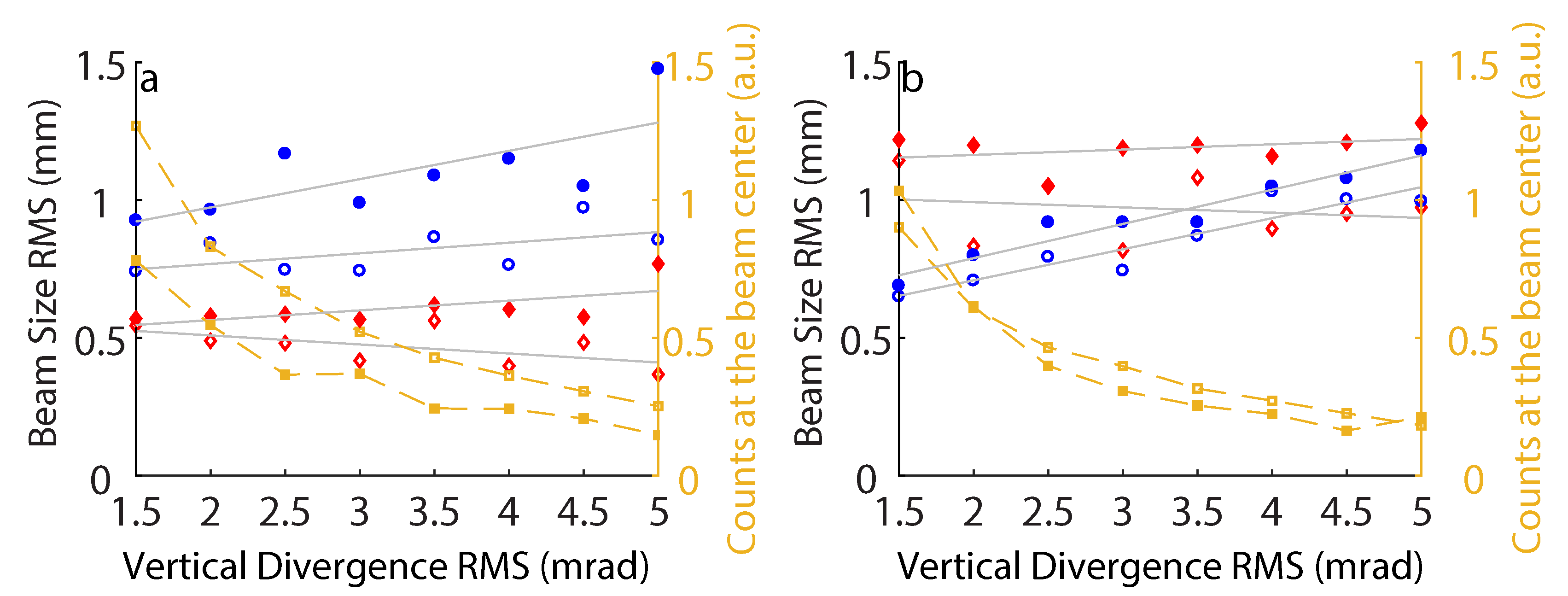
4.2. Variation of Initial Divergence
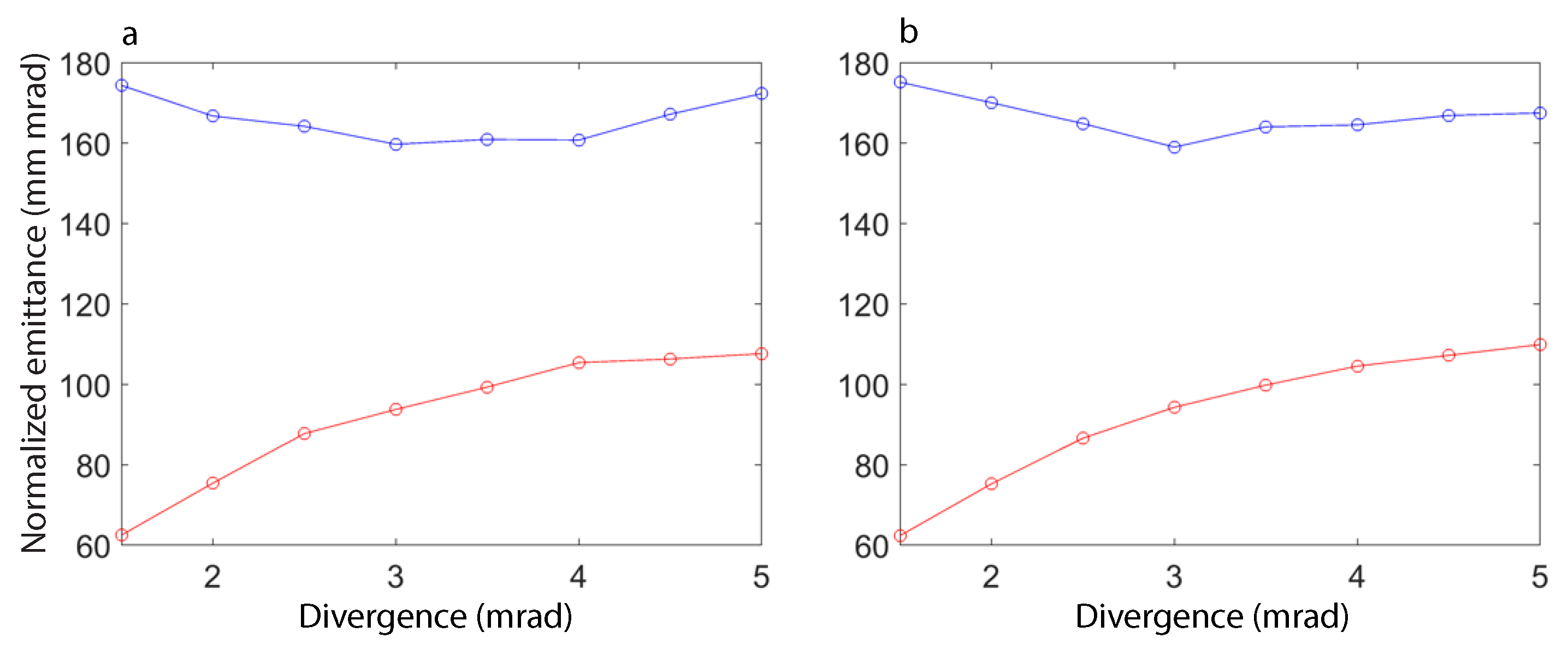
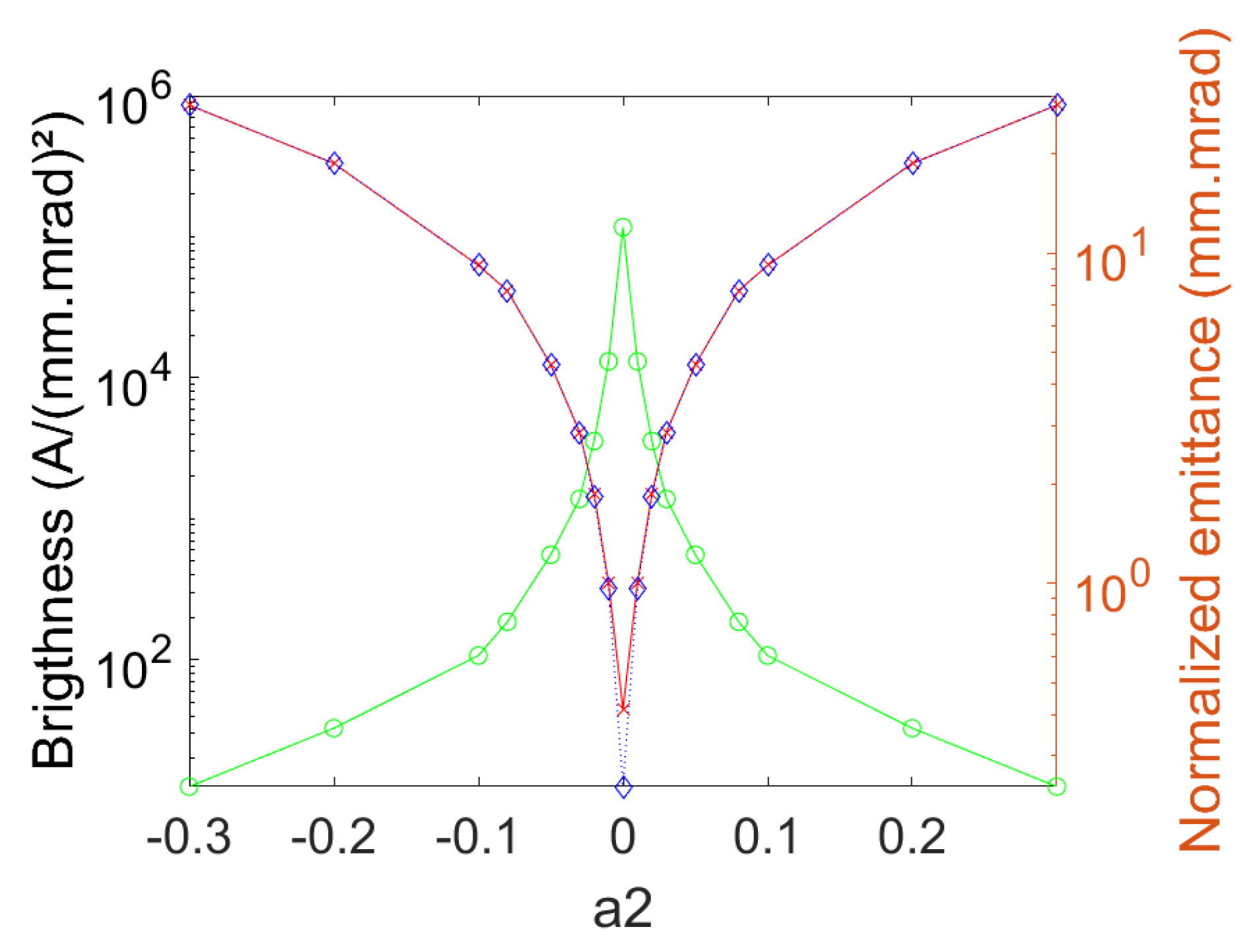
To investigate further the influence of the initial electron beam characteristics, the dependance of the transport on the σ z , i , while keeping the ratio between the vertical and horizontal divergence constant, is analyzed in Figure 10. For low a 2 (Figure 10a) at the undulator entrance, when the initial divergences grows, σ x remains similar, while σ z increases slightly and the charge decreases. When the beam is transported at the undulator exit (Figure 10b), the behavior is similar, with a larger growth of σ z . For high a 2 (Figure 10a) in the undulator entrance, σ z and σ x increase. The charge at 1.5 mrad divergence is much lower than for the low a 2 case and reaches the same level as for 3 mrad. When the beam exits the undulator (Figure 10b), both beam sizes increase, and the charge dependence is similar to the low a 2 case. The contribution of the skew term becomes more significant for larger initial divergence values, and thus, the beam size and resulting 2D emittance growth could be mitigated with electron beams presenting a small initial divergence.
The horizontal emittance at the undulator center increases with the divergence (see Figure 11a,b), going from 62 mm.mrad (62 mm.mrad) for σ z = 1.5 mrad to 107 mm.mrad (110 mm.mrad) for σ z = 5 mrad for the low (high) a 2 skew term. The vertical emittance decreases until σ z = 3 mrad and then starts to increase by a small amount, because of particle loss on the vertical aperture of the undulator associated to the increase of the divergence.

4.3. Brightness

Figure 12 shows the transversal beam shape versus a 2 at the undulator center. For a 2 = 0, the beam (see Figure 12a) is focused (beam horizontal size 0.67 mm and vertical size 0.37 mm RMS). For the low a 2 , the beam (see Figure 12b) is slightly defocused (beam horizontal size 0.73 mm and vertical size 0.38 mm RMS). For the high a 2 , the beam (see Figure 12c) exhibits a vertical and horizontal focusing redistribution per energy of the beam and a small tilt. The total beam emittance at the center of the undulator (see Table 5) increases by a small amount from a 2 = 0 ( ϵ x = 103 mm.mrad ϵ z = 30 mm.mrad) to low a 2 ( ϵ x = 119 mm.mrad ϵ z = 35 mm.mrad), with a factor 1.2 (1.16) horizontally (vertically), while keeping the charge at 2.82% of the initial beam one, which corresponds to a ±7 MeV slice around the reference energy thanks to the slit that cuts the useless electron energies. For the high a 2 , the increase is more important, the horizontal (vertical) emittance gets larger by a factor of 2.73 (6.71) from the low a 2 case, achieving ϵ x = 328 mm.mrad ϵ z = 234 mm.mrad, and the charge decreases to 1.4% of the initial beam one. Table 5 shows the emittance and charge for a “monochromatic” 176 ± 0.1 MeV slice of a flat top beam of central energy 176 MeV and σ γ = ±5%, at the center of the undulator. The emittance increases quickly with the presence of the a 2 skew term. From a 2 = 0 to low a 2 , an increase of 10 (4.7) of the horizontal (vertical) emittance takes place, and for the high a 2 skew term, an additional increase by a factor 1.7 (5.7) horizontally (vertically) occurs, attaining an emittance value of 8.29 mm.mrad horizontally and 6.56 mm.mrad vertically from the 0.48 mm.mrad and 0.24 mm.mrad value of emittance for the a 2 = 0 case. The emittance of the “monochromatic” 176 MeV is 2 orders of magnitude lower than the total beam emittance, showing that the chromatic effects dominate the total beam emittance behavior.
Figure 13 shows the horizontal and vertical emittance at the undulator center of an initial flat-top energy distribution electron beam versus energy spread. From the monochromatic beam ( σ γ = 0) to =5% energy spread, the emittance has a linear dependence versus energy spread, as shown in the chromatic term (see Equation (2)), with a slope of 12.4 mm.mrad/% (2.9 mm.mrad/%) in the horizontal (vertical) plane. ϵ x ( ϵ z ) increases to 63.8 mm.mrad (15.3 mm.mrad) for a σ γ = 5% spread. For σ γ larger than 1%, the chromatic emittance starts to dominate. For σ γ higher than 5%, ϵ x starts to converge around 74 mm.mrad and ϵ z to increase faster, because the lower and higher energies vertically defocus at the undulator and are thus cut by its physical aperture.
Table 5 shows the brightness calculated with Equation (1) for the total beam (with σ s of 980 ± 100 μ m) and the “monochromatic” beam (with σ s of 5.4 ± 0.2 μ m). Hence, the peak brightness is dominated by the horizontal and vertical emittance: As the emittance rapidly grows for high a 2 , the brightness decreases in a similar rate. For the total beam, the brightness decreases by a factor of 1.4 (42.8) from a 2 = 0 to the low a 2 case (high a 2 case). The total beam brightness is only substantially changed for the high a 2 term. For the 176 MeV “monochromatic” beam, the brightness decreases by a factor 51 (486) from a 2 = 0 to the low (high) a 2 case. Even the existence of a low a 2 term affects dramatically the slice brightness.
Figure 14 shows the brightness and horizontal emittance at the undulator center for a “monochromatic” 176 ± 0.1 MeV beam of 0.1 ± 0.02 pC with the ’slit-undulator’ optics while changing the skew component of QUAPEVA2 and considering the others ideal. For a 2 = 0, the emittance from the source to the center of the undulator is 0.41 mm.mrad and 0.28 mm.mrad horizontally and vertically, respectively. By increasing a 2 to ±0.03, the horizontal (vertical) emittance increases by a factor of 68 (116), reaching a value of 28 mm.mrad, following a linear dependence versus a 2 , as expected from the second term of Equation (2). σ s goes from 5.3 × 10 3 μ m for a 2 = 0 to 6.7 × 10 3 μ m for a 2 = ±0.3. Due to the small variations of σ s and charge, the brightness depends mainly on the emittance, so between a 2 = 0 and a 2 = 0.01, the brightness decreases by a factor of 9.

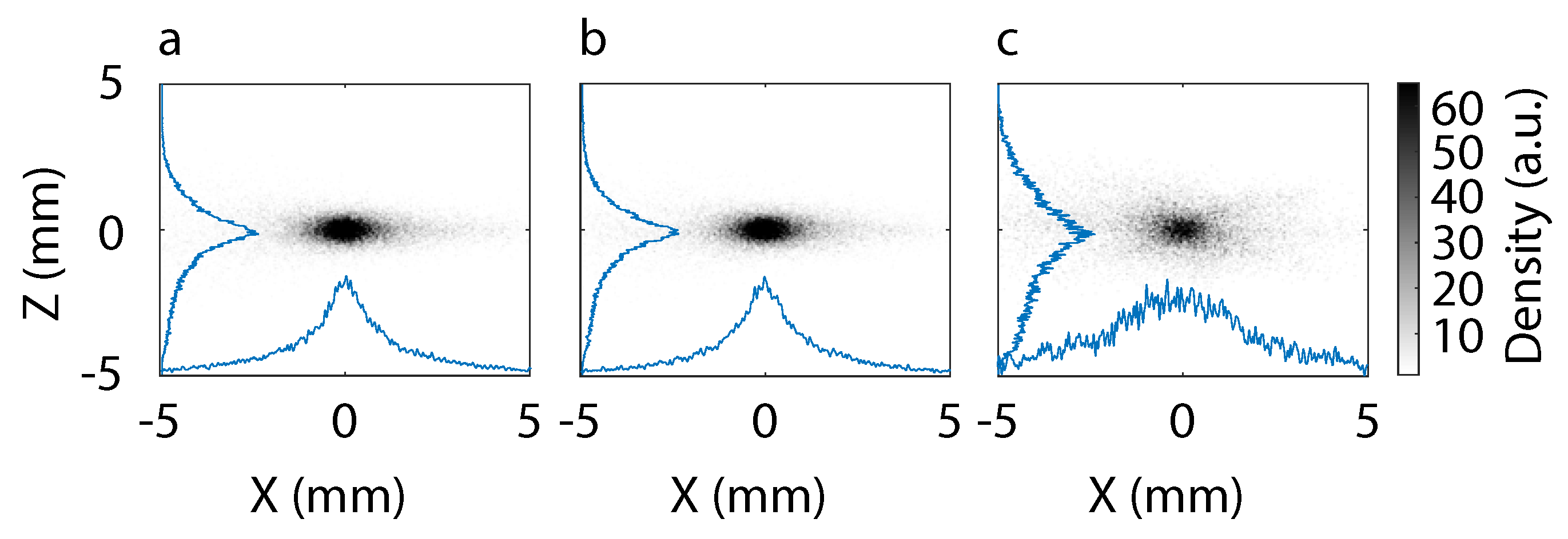
5. Measured Electron Beam Transport in Presence of Skew Quadrupolar Components of the First Triplet

The QUAPEVAs tunability gives a high capability to adjust the COXINEL line to the variations that the laser–plasma system undergoes during the experiments. During experiments, pointing variations with respect to the reference beam path of the LPA beam appearing can be compensated throughout the displacement of the magnetic center of the QUAPEVAs [41] using a response matrix method.
Figure 15a,b compares the measurements at the undulator entrance and simulation. The RMS beam sizes ( σ x = 0.52 mm σ z = 0.64 mm) are similar to the simulated ones ( σ x = 0.52 mm σ z = 0.65 mm). The slight difference may arise from the uncertainty of the initial distribution. A change of 6 T/m in QUAPEVA 2 from the configuration of Figure 15c,d causes the horizontal and vertical focusing redistribution, leading to a cross shape (see Figure 15c). The characteristic cross due to the gradient of QUAPEVA 2 is well reproduced in simulation (see Figure 15d). Figure 15e,f compares measurements and simulations at the undulator exit and shows similar experimental ( σ x = 0.77 mm σ z = 0.50 mm) and simulation RMS beam size ( σ x = 0.74 mm σ z = 0.35 mm).
Figure 16 compares measured and simulated transverse beam profiles at the undulator entrance. Similar round shapes are observed (Figure 16a,b), corresponding to a tight focus. The RMS experimental ( σ x = 1.31 mm σ x = 1.58 mm) and simulated ( σ x = 0.87 mm σ x = 2.32 mm) beam sizes differ slightly, probably because of an improper initial electron beam distribution. The cross shape with a tilt observed during measurements (Figure 16c,d) is well reproduced by simulations. A good agreement between measurements and simulations is also found on the beam slopes at the undulator exit (see Figure 16e,f). The cross pattern is rotated to the opposite side with respect to Figure 16c,d, because of the focusing effect of the undulator.

6. Conclusions

The behavior of the beam to different QUAPEVA gradients and a 2 terms was studied in the cases of a low and a high initial divergence beams analytically and through simulation and measurements. We show that the chromatic range of the beam makes it sensitive to the gradient of the QUAPEVA, especially QUAPEVA 2, the strongest one. Even small variations of the QUAPEVA 2 gradient cause an important horizontal and vertical focus position redistribution for each energy, leading to a characteristic cross shape pattern on the screen. For a given value of the skew component a 2 , this cross shape pattern becomes tilted, and the increase of the initial divergence enhances the effects: When the initial divergence is increased, the beam sizes increase, and the total charge decreases more strongly the higher the a 2 skew term. The emittance linear dependence on the QUAPEVA angle and energy spread found in the simulations is consistent with the chromatic and rotation terms of Equation (2). The emittance growth and the charge change lead to an important loss of slice and total beam brightness, harmful for FEL and possible future particle collider applications. Future improvements in the laser system will be able to increase the stability of the LPA system stability, and the use of different LPA schemes could improve the charge on the reference electron energy and also improve the initial electron energy distribution by reducing the energy spread.

Author Contributions

The line was designed by A.L. with M.-E.C. and M.L. and modeled by T.A., A.L. (Alexandre Loulergue), and E.R. S.C., J.-P.G., G.L., O.K., V.M., C.T. and A.T. worked on the laser based electron acceleration. The theoretical analysis was done by A.L. (Alexandre Loulergue) with D.O.E. Equipments were prepared by F.M., F.B., C.K., A.G. and M.-E.C. for the QUAPEVA, M.-E.C., A.G., C.K., F.M., and M.V. for the magnetic elements and the undulator, and T.A., M.-E.C., A.L. (Alain Lestrade), M.S. and M.L. for the diagnostics. Data were analyzed by T.A., S.C., A.G., M.-E.C., D.O.E., A.L. (Alexandre Loulergue), E.R., and C.K., T.A., S.C., M.-E.C., J.-P.G., D.O.E., A.G., G.L., A.L. (Alexandre Loulergue), M.L., and E.R. worked on the experiment. The paper was written by D.O.E., A.G., A.L. (Alexandre Loulergue), and M.-E.C.

Funding

This work was partially supported by the European Research Council for the Advanced Grants COXINEL (340015, PI: M.-E.C.) and X-Five (339128, PI: V.M.), EuPRAXIA design study (6538782), the Fondation de la Cooperation scientifique (QUAPEVA-2012-058T), the Agence Nationale de la Recherche [projet Blanc DYNACO 2010-042301], the Agence Nationale de la Recherche through the LABEX CEMPI (ANR-11-LABX-0007), the Ministry of Higher Education and Research, Hauts de France council, and European Regional Development Fund (ERDF) through the Contrat de Projets Etat-Region (CPER Photonics for Society P4S).

Acknowledgments

The authors acknowledge SOLEIL staff for their support and in particular, the Magnestism and Insertion device group, J. L. Lancelot, F. Forest, O. Cosson at Sigmaphi for the joint development of the QUAPEVA magnets, C. Benabderrahmane (ESRF) for the QUAPEVA, and J. Chavanne, G. Le Bec, C. Vallerand for the magnetic measurement bench at LAL.

Conflicts of Interest

The authors declare no conflict of interest.

References

  1. Tajima, T.; Dawson, J.M. Laser electron accelerator. Phys. Rev. Lett. 1979, 43, 267. [Google Scholar] [CrossRef]
  2. Esarey, E.; Schroeder, C.; Leemans, W. Physics of laser-driven plasma-based electron accelerators. Rev. Mod. Phys. 2009, 81, 1229–1285. [Google Scholar] [CrossRef]
  3. Strickland, D.; Mourou, G. Compression of amplified chirped optical pulses. Opt. Commun. 1985, 55, 447–449. [Google Scholar] [CrossRef]
  4. Geddes, C.; Toth, C.; Van Tilborg, J.; Esarey, E.; Schroeder, C.; Bruhwiler, D.; Nieter, C.; Cary, J.; Leemans, W. High-quality electron beams from a laser wakefield accelerator using plasma-channel guiding. Nature 2004, 431, 538–541. [Google Scholar] [CrossRef] [PubMed]
  5. Faure, J.; Glinec, Y.; Pukhov, A.; Kiselev, S.; Gordienko, S.; Lefebvre, E.; Rousseau, J.-P.; Burgy, F.; Malka, V. A laser-plasma accelerator producing monoenergetic electron beams. Nature 2004, 431, 541–544. [Google Scholar] [CrossRef] [PubMed]
  6. Mangles, S.; Murphy, C.D.; Najmudin, Z.; Thomas, A.G.R.; Collier, J.L.; Dangor, A.E.; Divall, E.J.; Foster, P.S.; Gallacher, J.G.; Hooker, C.J.; et al. Monoenergetic beams of relativistic electrons from intense laser-plasma interactions. Nature 2004, 431, 538–541. [Google Scholar] [CrossRef]
  7. Malka, V.; Faure, J.; Glinec, Y.; Pukhov, A.; Rousseau, J.P. Monoenergetic electron beam optimization in the bubble regime. Phys. Plasmas 2005, 12, 56702–56709. [Google Scholar] [CrossRef]
  8. Leemans, W.; Nagler, B.; Gonsalves, A.; Toth, C.; Nakamura, K.; Geddes, C.; Esarey, E.; Schroeder, C.; Hooker, S. GeV electron beams from a centimetre-scale accelerator. Nat. Phys. 2006, 2, 696–699. [Google Scholar] [CrossRef]
  9. Faure, J.; Rechatin, C.; Norlin, A.; Lifschitz, A.; Glinec, Y.; Malka, V. Controlled injection and acceleration of electrons in plasma wakefields by colliding laser pulses. Nature 2006, 444, 737–739. [Google Scholar] [CrossRef]
  10. Lu, W.; Tzoufras, M.; Joshi, C.; Tsung, F.S.; Mori, W.B.; Vieira, J.; Fonseca, R.A.; Silva, L.O. Generating multi-GeV electron bunches using single stage laser wakefield acceleration in a 3D nonlinear regime. Phys. Rev. Spec. Top. Accel. Beams 2007, 10, 061301–061312. [Google Scholar] [CrossRef]
  11. Cipiccia, S.; Islam, M.R.; Ersfeld, B.; Shanks, R.P.; Brunetti, E.; Vieux, G.; Yang, X.; Issac, R.C.; Wiggins, S.M. Gamma-rays from harmonically resonant betatron oscillations in a plasma wake. Nat. Phys. 2011, 7, 867–871. [Google Scholar] [CrossRef]
  12. Lundh, O.; Lim, J.; Rechatin, C.; Ammoura, L.; Ben-Ismail, A.; Davoine, X.; Gallot, G.; Goddet, J.-P.; Lefebvre, E.; Malka, V.; et al. Few femtosecond, few kiloampere electron bunch produced by a laser–plasma accelerator. Nat. Phys. 2011, 7, 219–222. [Google Scholar] [CrossRef]
  13. Rechatin, C.; Faure, J.; Ben-Ismail, A.; Lim, J.; Fitour, R.; Specka, A.; Videau, H.; Tafzi, A.; Burgy, F.; Malka, V. Controlling the phase-space volume of injected electrons in a laser-plasma accelerator. Phys. Rev. Lett. 2009, 102, 164801. [Google Scholar] [CrossRef] [PubMed]
  14. Geddes, C.G.R.; Nakamura, K.; Plateau, G.R.; Toth, C.; Cormier-Michel, E.; Esarey, E.; Schroeder, C.B.; Cary, J.R.; Leemans, W.P. Plasma-density-gradient injection of low absolute-momentum-spread electron bunches. Phys. Rev. Lett. 2008, 100, 215004. [Google Scholar] [CrossRef] [PubMed]
  15. Kalmykov, S.; Yi, S.; Khudik, V.; Shvets, G. Electron self-injection and trapping into an evolving plasma bubble. Phys. Rev. Lett. 2009, 103, 135004. [Google Scholar] [CrossRef]
  16. Faure, J.; Rechatin, C.; Lundh, O.; Ammoura, L.; Malka, V. Injection and acceleration of quasimonoenergetic relativistic electron beams using density gradients at the edges of a plasma channel. Phys. Plasmas 2010, 17, 083107. [Google Scholar] [CrossRef] [Green Version]
  17. Pollock, B.; Clayton, C.; Ralph, J.; Albert, F.; Davidson, A.; Divol, L.; Filip, C.; Glenzer, S.; Herpoldt, K.; Lu, W.; et al. Demonstration of a narrow energy spread, 0.5 GeV electron beam from a two-stage laser wakefield accelerator. Phys. Rev. Lett. 2011, 107, 045001. [Google Scholar] [CrossRef]
  18. Corde, S.; Thaury, C.; Lifschitz, A.; Lambert, G.; Phuoc, K.T.; Davoine, X.; Lehe, R.; Douillet, D.; Rousse, A.; Malka, V. Observation of longitudinal and transverse self-injections in laser-plasma accelerators. Nat. Commun. 2013, 4, 1501. [Google Scholar] [CrossRef] [Green Version]
  19. Leemans, W.; Gonsalves, A.; Mao, H.S.; Nakamura, K.; Benedetti, C.; Schroeder, C.; Tóth, C.; Daniels, J.; Mittelberger, D.; Bulanov, S.; et al. Multi-GeV electron beams from capillary-discharge-guided subpetawatt laser pulses in the self-trapping regime. Phys. Rev. Lett. 2014, 113, 245002. [Google Scholar] [CrossRef]
  20. Weingartner, R.; Raith, S.; Popp, A.; Chou, S.; Wenz, J.; Khrennikov, K.; Heigoldt, M.; Maier, A.R.; Kajumba, N.; Fuchs, M.; et al. Ultralow emittance electron beams from a laser-wakefield accelerator. Phys. Rev. Spec. Top. Accel. Beams 2012, 15, 111302. [Google Scholar] [CrossRef]
  21. Thaury, C.; Guillaume, E.; Lifschitz, A.; Phuoc, K.T.; Hansson, M.; Grittani, G.; Gautier, J.; Goddet, J.P.; Tafzi, A.; Lundh, O.; et al. Shock assisted ionization injection in laser-plasma accelerators. Sci. Rep. 2015, 5, 16310. [Google Scholar] [CrossRef] [PubMed] [Green Version]
  22. Esarey, E.; Hubbard, R.; Leemans, W.; Ting, A.; Sprangle, P. Electron injection into plasma wakefields by colliding laser pulses. Phys. Rev. Lett. 1997, 79, 2682–2685. [Google Scholar] [CrossRef]
  23. Bulanov, S.; Naumova, N.; Pegoraro, F.; Sakai, J. Particle injection into the wave acceleration phase due to nonlinear wake wave breaking. Phys. Rev. E 1998, 58, R5257. [Google Scholar] [CrossRef]
  24. Audet, T.; Hansson, M.; Lee, P.; Desforges, F.; Maynard, G.; Dobosz Dufrénoy, S.; Lehe, R.; Vay, J.L.; Aurand, B.; Persson, A.; et al. Investigation of ionization-induced electron injection in a wakefield driven by laser inside a gas cell. Phys. Plasmas 2016, 23, 023110. [Google Scholar] [CrossRef] [Green Version]
  25. Osterhoff, J.; Popp, A.; Major, Z.; Marx, B.; Rowlands-Rees, T.; Fuchs, M.; Geissler, M.; Hörlein, R.; Hidding, B.; Becker, S.; et al. Generation of stable, low-divergence electron beams by laser-wakefield acceleration in a steady-state-flow gas cell. Phys. Rev. Lett. 2008, 101, 085002. [Google Scholar] [CrossRef] [PubMed]
  26. McGuffey, C.; Thomas, A.; Schumaker, W.; Matsuoka, T.; Chvykov, V.; Dollar, F.; Kalintchenko, G.; Yanovsky, V.; Maksimchuk, A.; Krushelnick, K.; et al. Ionization induced trapping in a laser wakefield accelerator. Phys. Rev. Lett. 2010, 104, 025004. [Google Scholar] [CrossRef] [PubMed]
  27. Wang, X.; Zgadzaj, R.; Fazel, N.; Li, Z.; Yi, S.; Zhang, X.; Henderson, W.; Chang, Y.-Y.; Korzekwa, R.; Tsai, H.-E.; et al. Quasi-monoenergetic laser-plasma acceleration of electrons to 2 GeV. Nat. Commun. 2013, 4, 1988. [Google Scholar] [CrossRef] [PubMed] [Green Version]
  28. Schroeder, C.; Esarey, E.; Geddes, C.; Benedetti, C.; Leemans, W. Physics considerations for laser-plasma linear colliders. Phys. Rev. Spec. Top. Accel. Beams 2010, 13, 101301. [Google Scholar] [CrossRef] [Green Version]
  29. Molodozhentsev, A.; Pribyl, L. ELI Eectron Beam Line for Laser-plasma-driven Undulator X-ray Source. In Proceedings of the IPAC2016, Busan, Korea, 8–13 May 2016. [Google Scholar]
  30. Madey, J.M. Stimulated emission of bremsstrahlung in a periodic magnetic field. J. Appl. Phys. 1971, 42, 1906–1913. [Google Scholar] [CrossRef]
  31. Kondratenko, A.; Saldin, E. Generating of coherent radiation by a relativistic electron beam in an ondulator. Part. Accel. 1980, 10, 207–216. [Google Scholar]
  32. Huang, Z.; Kim, K.J. Review of X-ray free-electron laser theory. Phys. Rev. Spec. Top. Accel. Beams 2007, 10, 034801. [Google Scholar] [CrossRef]
  33. Couprie, M.E. New generation of light sources: Present and future. J. Electron Spectrosc. Relat. Phenom. 2014, 196, 3–13. [Google Scholar] [CrossRef] [Green Version]
  34. Grüner, F.; Becker, S.; Schramm, U.; Eichner, T.; Fuchs, M.; Weingartner, R.; Habs, D.; Meyer-ter-Vehn, J.; Geissler, M.; Ferrario, M.; et al. Design considerations for table-top, laser-based VUV and X-ray free electron lasers. Appl. Phys. B 2007, 86, 431–435. [Google Scholar] [CrossRef] [Green Version]
  35. Nakajima, K. Compact X-ray sources: Towards a table-top free-electron laser. Nat. Phys. 2008, 4, 92–93. [Google Scholar] [CrossRef]
  36. Steinke, S.; Van Tilborg, J.; Benedetti, C.; Geddes, C.G.R.; Schroeder, C.B.; Daniels, J.; Swanson, K.K.; Gonsalves, A.J.; Nakamura, K.; Matlis, N.H.; et al. Multistage coupling of independent laser-plasma accelerators. Nature 2016, 530, 190–193. [Google Scholar] [CrossRef]
  37. Hosokai, T.; Zhidkov, A.; Yamazaki, A.; Mizuta, Y.; Uesaka, M.; Kodama, R. Electron energy boosting in laser-wake-field acceleration with external magnetic field B 1 T and laser prepulses. Appl. Phys. Lett. 2010, 96, 121501. [Google Scholar] [CrossRef]
  38. Fuchs, M.; Weingartner, R.; Popp, A.; Major, Z.; Becker, S.; Osterhoff, J.; Cortrie, I.; Zeitler, B.; Hörlein, R.; Tsakiris, G.D.; et al. Laser-driven soft-X-ray undulator source. Nat. Phys. 2009, 5, 826–829. [Google Scholar] [CrossRef] [Green Version]
  39. Anania, M.P.; Clark, D.; van der Geer, S.B.; de Loos, M.J.; Isaac, R.; Reitsma, A.J.W.; Welsh, G.H.; Wiggins, S.M.; Jaroszynski, D.A. Transport of ultra-short electron bunches in a free-electron laser driven by a laser-plasma wakefield accelerator. In Conference on Harnessing Relativistic Plasma Waves as Novel Radiation Sources from Terahertz to X-rays and Beyond; International Society for Optics and Photonics: Bellingham, WA, USA, 2009; p. 735916. [Google Scholar]
  40. Lambert, G.; Corde, S.; Phuoc, K.T.; Malka, V.; Ismail, A.B.; Benveniste, E.; Specka, A.; Labat, M.; Loulergue, A.; Bachelard, R.; et al. Progress on the generation of undulator radiation in the UV from a plasma-based electron beam. In Proceedings of the 34th International Free-Electron Laser Conference, Nara, Japan, 16–31 August 2012; p. 2. [Google Scholar]
  41. André, T.; Andriyash, I.A.; Loulergue, A.; Labat, M.; Roussel, E.; Ghaith, A.; Khojoyan, M.; Thaury, C.; Valléau, M.; Briquez, F.; et al. Control of laser plasma accelerated electrons for light sources. Nat. Commun. 2018, 9, 1334. [Google Scholar] [CrossRef]
  42. Floettmann, K. Some basic features of the beam emittance. Phys. Rev. Spec. Top. Accel. Beams 2003, 6, 034202. [Google Scholar] [CrossRef] [Green Version]
  43. Floettmann, K. Erratum: Some basic features of the beam emittance. Phys. Rev. Spec. Top. Accel. Beams 2003, 6, 079901. [Google Scholar] [CrossRef]
  44. Antici, P.; Bacci, A.; Benedetti, C.; Chiadroni, E.; Ferrario, M.; Rossi, A.R.; Lancia, L.; Migliorati, M.; Mostacci, A.; Palumbo, L.; et al. Laser-driven electron beamlines generated by coupling laser-plasma sources with conventional transport systems. J. Appl. Phys. 2012, 112, 044902. [Google Scholar] [CrossRef]
  45. Migliorati, M.; Bacci, A.; Benedetti, C.; Chiadroni, E.; Ferrario, M.; Mostacci, A.; Palumbo, L.; Rossi, A.R.; Serafini, L.; Antici, P.; et al. Intrinsic normalized emittance growth in laser-driven electron accelerators. Phys. Rev. Spec. Top. Accel. Beams 2013, 16, 011302. [Google Scholar] [CrossRef]
  46. Floettmann, K.; Paramonov, V.V. Beam dynamics in transverse deflecting rf structures. Phys. Rev. Spec. Top. Accel. Beams 2014, 17, 024001. [Google Scholar] [CrossRef]
  47. Dornmair, I.I.; Dornmair, K. Floettmann, and AR Maier. Phys. Rev. Spec. Top. Accel. Beams 2015, 18, 041302. [Google Scholar] [CrossRef]
  48. Li, X.; Chancé, A.; Nghiem, P.A.P. Preserving emittance by matching out and matching in plasma wakefield acceleration stage. Phys. Rev. Accel. Beams 2019, 22, 021304. [Google Scholar] [CrossRef] [Green Version]
  49. Mihara, T. A Super Strong Permanent Magnet Quadrupole for the Final Focus in a Linear Collider; Technical Report; SLAC National Accelerator Lab.: Menlo Park, CA, USA, 2018. [Google Scholar]
  50. Ghaith, A.; Kitegi, C.; André, T.; Valléau, M.; Marteau, F.; Vétéran, J.; Blache, F.; Benabderrahmane, C.; Cosson, O.; Forest, F.; et al. Tunable high gradient quadrupoles for a laser plasma acceleration based FEL. Nucl. Instrum. Methods Phys. Res. Sect. A Accel. Spectrom. Detect. Assoc. Equip. 2018, 909, 290–293. [Google Scholar] [CrossRef]
  51. Hosokai, T.; Kando, M.; Dewa, H.; Kotaki, H.; Kondo, S.; Hasegawa, N.; Nakajima, K.; Horioka, K. Optical guidance of terrawatt laser pulses by the implosion phase of a fast Z-pinch discharge in a gas-filled capillary. Opt. Lett. 2000, 25, 10–12. [Google Scholar] [CrossRef]
  52. Thaury, C.; Guillaume, E.; Döpp, A.; Lehe, R.; Lifschitz, A.; Phuoc, K.T.; Gautier, J.; Goddet, J.-P.; Tafzi, A.; Flacco, A.; et al. Demonstration of relativistic electron beam focusing by a laser-plasma lens. Nat. Commun. 2015, 6, 6860. [Google Scholar] [CrossRef]
  53. Van Tilborg, J.; Steinke, S.; Geddes, C.; Matlis, N.; Shaw, B.; Gonsalves, A.; Huijts, J.; Nakamura, K.; Daniels, J.; Schroeder, C.; et al. Active plasma lensing for relativistic laser-plasma-accelerated electron beams. Phys. Rev. Lett. 2015, 115, 184802. [Google Scholar] [CrossRef]
  54. Pompili, R.; Anania, M.; Bellaveglia, M.; Biagioni, A.; Bini, S.; Bisesto, F.; Brentegani, E.; Castorina, G.; Chiadroni, E.; Cianchi, A.; et al. Experimental characterization of active plasma lensing for electron beams. Appl. Phys. Lett. 2017, 110, 104101. [Google Scholar] [CrossRef]
  55. Van Tilborg, J.; Barber, S.; Benedetti, C.; Schroeder, C.; Isono, F.; Tsai, H.E.; Geddes, C.; Leemans, W. Comparative study of active plasma lenses in high-quality electron accelerator transport lines. Phys. Plasmas 2018, 25, 056702. [Google Scholar] [CrossRef] [Green Version]
  56. Lim, J.; Frigola, P.; Travish, G.; Rosenzweig, J.; Anderson, S.; Brown, W.; Jacob, J.; Robbins, C.; Tremaine, A. Adjustable, short focal length permanent-magnet quadrupole based electron beam final focus system. Phys. Rev. Spec. Top. Accel. Beams 2005, 8, 072401. [Google Scholar] [CrossRef] [Green Version]
  57. Marteau, F.; Ghaith, A.; N’Gotta, P.; Benabderrahmane, C.; Valléau, M.; Kitegi, C.; Loulergue, A.; Vétéran, J.; Sebdaoui, M.; André, T.; et al. Variable high gradient permanent magnet quadrupole (QUAPEVA). Appl. Phys. Lett. 2017, 111, 253503. [Google Scholar] [CrossRef]
  58. Ghaith, A.; Kitegi, C.; Andre, T.; Valleau, M.; Marteau, F.; Veteran, J.; Blache, F.; Benabderrahmane, C.; Cosson, O.; Forest, F.; et al. Tunable High Gradient Quadrupoles For A Laser Plasma Acceleration Based FEL. arXiv 2017, arXiv:1712.03857. [Google Scholar] [CrossRef]
  59. Mihara, T.; Iwashita, Y.; Kumada, M.; Evgeny, A.; Spencer, C.M. Super strong permanent magnet quadrupole for a linear collider. IEEE Trans. Appl. Supercond. 2004, 14, 469–472. [Google Scholar] [CrossRef]
  60. Iwashita, Y.; Mihara, T.; Antokhin, E.; Kumada, M.; Aoki, M. Permanent magnet quadrupole for final focus for linear collider. In Proceedings of the IEEE 2003 Particle Accelerator Conference, Portland, OR, USA, 12–16 May 2003; Volume 4, pp. 2198–2200. [Google Scholar]
  61. Cesar, D.; Maxson, J.; Musumeci, P.; Sun, Y.; Harrison, J.; Frigola, P.; O’Shea, F.; To, H.; Alesini, D.; Li, R. Demonstration of single-shot picosecond time-resolved MeV electron imaging using a compact permanent magnet quadrupole based lens. Phys. Rev. Lett. 2016, 117, 024801. [Google Scholar] [CrossRef]
  62. Zhou, Z.; Tang, C.; Rui, T.; Du, Y.C.; Li, F.; Gai, W.; Huang, W. Compact High Energy Electron Radiography System Based on Permanent Magnet Quadrupole. In Proceedings of the 8th International Particle Accelerator Conference (IPAC’17), Copenhagen, Denmark, 14–19 May 2017. [Google Scholar]
  63. Eichner, T.; Grüner, F.; Becker, S.; Fuchs, M.; Habs, D.; Weingartner, R.; Schramm, U.; Backe, H.; Kunz, P.; Lauth, W. Miniature magnetic devices for laser-based, table-top free-electron lasers. Phys. Rev. Spec. Top. Accel. Beams 2007, 10, 082401. [Google Scholar] [CrossRef] [Green Version]
  64. Mihara, T.; Iwashita, Y.; Kumada, M.; Spencer, C.M. Variable permanent magnet quadrupole. IEEE Trans. Appl. Supercond. 2006, 16, 224–227. [Google Scholar] [CrossRef]
  65. Iwashita, Y.; Mihara, T.; Kyoto, U.; Uji, K.; Kumada, J.M.; NIRS, C.; Spencer, J.C. Super strong adjustable permanent magnet quadrupole for the final focus in a linear collider. In Proceedings of the 10th European Particle Accelerator Conference (EPAC), Edinburgh, UK, 26–30 Junuary 2006; Volume 6, pp. 2550–2552. [Google Scholar]
  66. Gottschalk, S.C.; Taylor, D.J. Magnetic and engineering analysis of an adjustable strength permanent magnet quadrupole. In Proceedings of the 2005 IEEE Particle Accelerator Conference, Knoxville, TN, USA, 16–20 May 2005; pp. 2122–2124. [Google Scholar]
  67. Couprie, M.; Labat, M.; Evain, C.; Marteau, F.; Briquez, F.; Khojoyan, M.; Benabderrahmane, C.; Chapuis, L.; Hubert, N.; Bourassin-Bouchet, C.; et al. An application of laser–plasma acceleration: Towards a free-electron laser amplification. Plasma Phys. Control. Fusion 2016, 58, 034020. [Google Scholar] [CrossRef]
  68. Easton, M.J.; Li, H.; Lu, Y.; Zhu, J.; Pfister, P.D. Permanent-magnet quadrupoles for an interdigital H-mode drift tube linear accelerator: Optimization code and adjustable magnet design. Phys. Rev. Accel. Beams 2018, 21, 122401. [Google Scholar] [CrossRef]
  69. Rosenzweig, J.; Chen, P. Beam optics of a self-focusing plasma lens. Phys. Rev. D 1989, 39, 2039–2045. [Google Scholar] [CrossRef] [Green Version]
  70. Lejeune, C.; Aubert, J. Emittance and brightness: Definitions and measurements. Appl. Charged Part. Opt. 1980, 1, 159–259. [Google Scholar]
  71. Mostacci, A.; Bellaveglia, M.; Chiadroni, E.; Cianchi, A.; Ferrario, M.; Filippetto, D.; Gatti, G.; Ronsivalle, C. Chromatic effects in quadrupole scan emittance measurements. Phys. Rev. Spec. Top. Accel. Beams 2012, 15, 082802. [Google Scholar] [CrossRef]
  72. Labat, M.; Loulergue, L.; André, T.; Andriyash, I.; Ghaith, A.; Khojoyan, M.; Marteau, F.; Valleau, M.; Briquez, F.; Benabderrahmane, C. Robustness of a plasma acceleration based Free Electron Laser. arXiv 2018, arXiv:1806.10848. [Google Scholar] [CrossRef]
  73. Khojoyan, M.; Briquez, F.; Labat, M.; Loulergue, A.; Marcouillé, O.; Marteau, F.; Sharma, G.; Couprie, M.E. Transport studies of LPA electron beam towards the FEL amplification at COXINEL. Nucl. Instrum. Methods Phys. Res. Sect. A 2016, 829, 260–264. [Google Scholar] [CrossRef] [Green Version]
  74. André, T.; Andriyash, I.; Basset, C.; Benabderrahmane, C.; Berteaud, P.; Bielawski, S.; Bonnin, S.; Bouvet, F.; Briquez, F.; Cassinari, L.; et al. First electron beam measurements on coxinel. In Proceedings of the 7th International Particle Accelerator Conference (IPAC’16), Busan, Korea, 8–13 May 2016; pp. 712–715. [Google Scholar]
  75. Bonifacio, R.; Pellegrini, C.; Narducci, L.M. Collective instabilities and high-gain regime in a free electron laser. Opt. Commun. 1984, 50, 373–378. [Google Scholar] [CrossRef] [Green Version]
  76. Maier, A.; Meseck, A.; Reiche, S.; Schroeder, C.; Seggebrock, T.; Gruener, F. Demonstration scheme for a laser-plasma-driven free-electron laser. Phys. Rev. X 2012, 2, 031019. [Google Scholar] [CrossRef]
  77. Couprie, M.E.; Loulergue, A.; Labat, M.; Lehe, R.; Malka, V. Towards a free electron laser based on laser plasma accelerators. J. Phys. B 2014, 47, 234001. [Google Scholar] [CrossRef]
  78. Loulergue, A.; Labat, M.; Evain, C.; Benabderrahmane, C.; Malka, V.; Couprie, M.E. Beam manipulation for compact laser wakefield accelerator based free-electron lasers. New J. Phys. 2015, 17, 023028. [Google Scholar] [CrossRef]
  79. Huang, Z.; Ding, Y.; Schroeder, C.B. Compact X-ray free-electron laser from a laser-plasma accelerator using a transverse-gradient undulator. Phys. Rev. Lett. 2012, 109, 204801. [Google Scholar] [CrossRef]
  80. Liu, T.; Zhang, T.; Wang, D.; Huang, Z. Compact beam transport system for free-electron lasers driven by a laser plasma accelerator. Phys. Rev. Accel. Beams 2017, 20, 020701. [Google Scholar] [CrossRef]
  81. Dattoli, G.; Renieri, A.; Torre, A. Lectures on the Free Electron Laser Theory and Related Topics; World Scientific: Singapore, 1993. [Google Scholar]
  82. Madur, A. Contribution à la Métrologie Magnétique des Multipôles D’accélérateurs: Les Quadrupôles du Synchroton SOLEIL; Vandoeuvre-les-Nancy, Institut National Polytechnique de Lorraine: Nancy, France, 2006. [Google Scholar]
  83. Lebec, G.; Chavanne, J.; Penel, C. Stretched-wire Measurements of Small Bore Multipole Magnets. Phys. Rev. Spec. Top. Accel. Beams 2012, 15. [Google Scholar] [CrossRef]
  84. Payet, J.; Chance, A.; Loulergue, A.; Ropert, A.; Meot, F.; Filhol, J.M.; Laclare, J.-L.; Farvacque, L.; Aniel, T. BETA Code; CEA: Saclay, France, 2001. [Google Scholar]
  85. Flöttmann, K.; Astra, A. A Space Charge Tracking Algorithm. ASTRA, 2007. Available online: http://www.desy.de/~mpyflo/ (accessed on 1 February 2019).
  86. Borland, M. Elegant: A Flexible SDDS-Compliant Code for Accelerator Simulation; Technical Report; Argonne National Lab.: Lemont, IL, USA, 2000.
  87. Agapov, I.; Geloni, G.; Tomin, S.; Zagorodnov, I. OCELOT: A software framework for synchrotron light source and FEL studies. Nucl. Instrum. Methods Phys. Res. Sect. A Accel. Spectrom. Detect. Assoc. Equip. 2014, 768, 151–156. [Google Scholar] [CrossRef]
Figure 1. COXINEL transport line scheme. Left to right: Laser pulse focused on a gas jet (blue), triplet of QUAPEVAs (grey), first screen for electron beam profile measurement (white), chicane (red), a second set of electro-magnetic quadrupoles (blue), screen before and after the undulator (white), and cryo-ready undulator (purple).
Applsci 09 02447 g001
Figure 2. Initial beam electron distribution (black), vertical (blue), and horizontal (red) divergence. (a) Low divergence beam (average over a set of 20 distributions), (b) high divergence beam (single-shot).
Applsci 09 02447 g002
Figure 3. (a) QUAPEVA magnetic design with different orientation of the cylindrical magnets: maximum (left), intermediate (middle), minimum gradient (right). (b) Mechanical shims applied to one of the QUAPEVAs to compensate for the skew terms.
Applsci 09 02447 g003
Figure 4. Skew quadrupolar term ( a 2 ) measured with the stretched wire, before (∘) and after (•) correction, for the QUAPEVA triplet: 26 mm (left), 40.7 mm (middle), and 44.7 mm (right), r 0 = 4 mm.
Applsci 09 02447 g004
Figure 5. Simulation of the horizontal (red) and vertical (blue) (relative energy spread (RMS)) beam envelope of the optics (a) “undulator”, (b) “slit-undulator”, (c) “undulator-entrance”, and (d) “undulator-exit” along the line for a flat-top energy spectrum beam of 176 ± 0.3 MeV, with σ z , i = 2 mrad RMS and σ x , i = 3.12 mrad RMS. Transversal distribution of the electron beam at the undulator entrance (a1d1), center (a2d2), and exit (a3d3) for the low divergence beam case (parameters of Figure 2a and Table 1) associated with the corresponding magnetic elements settings given in Table 3. Transport line elements representation (black) with screens (vertical line), dipoles (rectangle), and focusing (rectangle with indentation) and defocusing quadrupoles (triangle on top). (e) Vertical aperture along the longitudinal direction of the transport line.
Applsci 09 02447 g005
Figure 6. Simulated vertical (a) horizontal (b) RMS beam envelope along the line. (c) Vertical (blue) and horizontal (red) normalized emittance at the undulator center and total beam charge (green). Case of flat-top beams of 180 ± 0.3 MeV (dashed line), 176 ± 0.3 MeV (solid line), and 172 ± 0.3 MeV (dotted line), with the “Undulator” optics, an σ z , i = 2 mrad RMS and σ x , i = 3.12 mrad RMS, charge of 1 pC, ϵ x , i , ϵ z , i = 0.2 mm.mrad.
Applsci 09 02447 g006
Figure 7. Electron beam transverse shape (top) and corresponding vertical–horizontal position per energy (bottom) at the undulator exit for the relative gradient change of QUAPEVA 2 of ±3, ±1, and 0%. Case of “undulator entrance” optics with the low divergence beam distribution (Figure 2a and Table 1), ϵ x , i , ϵ z , i = 0.2 mm.mrad, σ z , i = 2 mrad, σ x , i = 3.12 mrad.
Applsci 09 02447 g007
Figure 8. (a) Horizontal (⋄) and vertical () RMS beam size and counts at the center of the beam (□) for the “undulator entrance” optics (each point averaged over 5 repetitions of the simulation) and (b) beam vertical () and horizontal (∘) normalized emittance and total charge () at the undulator center for the optics ’undulator’, for the relative gradient change of QUAPEVA 2 using the low divergence initial beam distribution (Figure 2a and Table 1) with σ z , i = 2 mrad, σ x , i = 3.12 mrad, and ϵ x , i = ϵ z , i = 0.2 mm.mrad.
Applsci 09 02447 g008
Figure 9. Electron beam transversal shape and vertical–horizontal position per energy at the screens before (ac,gi) and after (df,jl) the undulator for low (b,e,h,k), high (c,f,i,l), and null (a,d,g,j) a 2 terms (values of Table 2). (af) Low divergence electron beam distribution (Figure 2a) with σ z , i = 2 mrad, σ x , i = 3.12 mrad, and ϵ x , i , ϵ z , i = 0.2 mm.mrad (see Table 1). (gl) High divergence electron beam distribution (Figure 2b) with an initial σ z , i = 5 mrad, σ x , i = 11.75 mrad, and ϵ x , i , ϵ z , i = 0.2 mm.mrad (see Table 1). Transport with the “undulator entrance” optics and “undulator exit” optics.
Applsci 09 02447 g009
Figure 10. Counts at the center of the beam (), horizontal (⋄), and vertical () beam RMS size versus initial divergence for the low (void symbols) and high (filled symbols) skew (Table 2) for the electron distribution of Figure 2a, Table 1, (a) before and (b) after the undulator with the “undulator-entrance” optics and “undulator-exit” optics, respectively. Each point averaged over 5 repetitions of the simulation.
Applsci 09 02447 g010
Figure 11. Vertical (blue) and horizontal (red) normalized emittance versus the initial vertical divergence at the undulator center for the low (a) and high (b) skew case (Table 2) with the low divergence electron distribution (see Figure 2a, Table 1) and the “undulator” optics.
Applsci 09 02447 g011
Figure 12. Simulated transversal beam shape at the undulator center for (a) a 2 = 0, the (b) low and (c) high a 2 (Table 2). ’Slit-undulator’ optics (slit open to 3.2 mm corresponding to a slice of 176 ± 7 MeV). Initial low divergence beam distribution of Figure 2a with σ z , i = 2 mrad, σ x , i = 3.12 mrad ϵ z , i , ϵ x , i = 0.2 mm.mrad.
Applsci 09 02447 g012
Figure 13. Simulated horizontal (red) and vertical (blue) normalized emittance of the electron beam at the undulator center for the low a 2 skew terms (Table 2) and the optics “slit-undulator” without slit using flat-top electron beams for different energy spread with 176 MeV central energy, σ z , i = 2 mrad, σ x , i = 3.12 mrad, and ϵ z , i , ϵ x , i = 0.2 mm.mrad.
Applsci 09 02447 g013
Figure 14. Brightness () of the electron beam at the center of the undulator versus QUAPEVA 2 a 2 skew term and horizontal (x) and vertical () normalized emittance in log scale. Simulation using a “monochromatic” 176 ± 0.1 MeV beam with σ z , i = 2 mrad and σ x , i = 3.12 mrad, a charge of 0.1 ± 0.02 pC, ϵ z , i , ϵ x , i = 0.2 mm.mrad, transported with the “slit-undulator” optics and the slit in the chicane open to 3.2 mm.
Applsci 09 02447 g014
Figure 15. Transverse beam shape at the undulator entrance: measurements (a,c,e) and simulations (b,d,f) with the low skew a 2 case (Table 2), σ z , i = 2 mrad and σ x , i = 3.12 mrad, ϵ z , i , ϵ x , i = 0.2 mm.mrad. (a,b) “Undulator entrance” optics, QUAPEVA 1: 103.27 T/m, QUAPEVA 2: −115.65 T/m, QUAPEVA 3: 94.94 T/m, (c,d) QUAPEVA 1: 103.27 T/m, QUAPEVA 2: −121.99 T/m, QUAPEVA 3: 94.94 T/m. (e,f) With the “slit-undulator” optics, a horizontal pointing of 5 mrad and the slit in the chicane closed at 1 mm (177 ± 2 MeV). Shot-to-shot pointing for (a,c,e): 0.005 ± 0.01 mrad, −0.09 ± 0.06 mrad, and 0.17 ± 0.49 mrad (0.03 ± 0.02 mrad, 0.10 ± 0.08 mrad, −0.18 ± 0.01 mrad) in the horizontal (vertical) direction.
Applsci 09 02447 g015
Figure 16. Transverse beam shape at the undulator entrance: measurements (a,c,e) and simulations (b,d,f). Simulations done with the high skew a 2 case (Table 2), ϵ z , i , ϵ x , i = 0.2 mm.mrad. (a,b) With σ z , i = 2 mrad, σ x , i = 4.7 mrad and the “Undulator entrance” optics. (c,d) With σ z , i = 2 mrad, σ x , i = 4.7 mrad and the “Undulator” optics. (e,f) With σ z , i = 2.5 mrad, σ x , i = 5.9 mrad and the “Undulator exit” optics. Shot-to-shot pointing for (a,c,e): 0.85 ± 0.03 mrad, 0.13 ± 0.15 mrad, and 0.07 ± 0.02 mrad (−0.03 ± 0.05 mrad, −0.03 ± 0.04 mrad, 0.18 ± 0.04 mrad) in the horizontal (vertical) direction.
Applsci 09 02447 g016
Table 1. Initial input beam parameters.
Initial ParameterSymbolValueUnit
Case Low Divergence CaseHigh Divergence Case
Emittance ϵ x , i ϵ z , i 0.20.2mm.mrad
Ratio 1.562.35
Vertical divergence at 176 MeV σ z , i 2.05mrad (RMS)
Horizontal divergence at 176 MeV σ x , i 3.1211.75mrad (RMS)
Bunch longitudinal length σ s , i 10 6 10 6 m (RMS)
ChargeQ100100pC
Number of macro particlesN 10 6 10 6
Table 2. Multipolar terms before (high skew terms case) and after (low skew terms case) correction.
High Skew Term CaseLow Skew Term Case
Magnetic Lengtha2a6b2b6Angle (mrad)a2a6b2b6Angle (mrad)
26 mm0.073−0.00310.9510.1923.3−0.007−0.0110.9470.186−0.3
40.7 mm−0.325−0.01717.4750.326−90.027−017.4480.3290.7
44.7 mm0.3620.012−19.181−0.363−9.40.003−0.004−19.148−0.3570.05
Table 3. Magnetic elements characteristics per optics configuration.
OpticsQUAPEVAs
(QAP)
Chicane
Dipoles
Electro-Magnetic
Quadrupoles (QEM)
Unit ComponentGradient
T/m
B Field
T
Gap
mm
Current
A
r56
mm
Gradient
T/m
QAP1QAP2QAP3 QEM1QEM2QEM3QEM4
“Undulator”+102.68−101.14+89.100.242546.54.3−0.520.85−1.230.46
“Slit-undulator”+104.1−103+96.430.242546.54.3−0.014.70−4.400.29
“Undulator entrance”+102.8−101.2+90.260.242546.54.30000
“Undulator exit”+102.41−100.74+89.780.242546.54.3−1.741.26−1.360.41
Table 4. Counts at the center of the beam, RMS horizontal and vertical beam size for the different skew cases and beam distributions on the screen before and after the undulator. Each point averaged over 5 repetitions of the simulation.
Skew TermLow Divergence BeamHigh Divergence Beam
σ x , RMS (mm) σ z , RMS (mm)Beam Center Counts (a.u.) σ x , RMS (mm) σ z , RMS (mm)Beam Center Counts (a.u.)
Undulator entrance (“undulator-entrance” optics)
a 2 = 00.520.801.000.631.080.20
Low0.510.721.160.601.200.20
High0.631.010.780.981.980.14
Undulator exit (“undulator-exit” optics)
a 2 = 00.950.730.760.920.990.17
Low0.950.760.750.851.010.14
High1.220.830.501.310.970.11
Table 5. Horizontal and vertical normalized emittance and charge percentage arriving of the electron beam at the undulator center for a 2 = 0, low and high a 2 (Table 2) cases. Simulation using the low divergence initial beam distribution (Figure 2a), 176 MeV “monochromatic” beam with σ z , i = 2 mrad, σ x , i = 3.12 , initial charge 100 pC, mrad ϵ z , i , ϵ x , i = 0.2 mm.mrad, transported with the “slit-undulator” optics (slit closed to 3.2 mm corresponding to a slice of 176 ± 7  MeV). Each point averaged over 5 repetitions of the simulation.
Total Beam176 MeV “Monochromatic” Beam
Skew Term ϵ x , RMS
(mm.mrad)
ϵ z , RMS
(mm.mrad)
Charge
%
Brightness
(A/(mm.mrad))2
ϵ x , RMS
(mm.mrad)
ϵ z , RMS
(mm.mrad)
Charge
%
Brightness
(A/(mm.mrad))2
a 2 = 0103302.826.200.480.240.33.6 × 10 6
Low a 2 case119352.794.564.831.140.37.0 × 10 4
High a 2 case3282341.370.148.296.560.37.4 × 10 3

