1. Introduction
Digital image correlation (DIC) is one of a number of optical full-field technologies used to measure the shape and deformation characteristics of a wide range of materials. The theory and principles of DIC can be read in various publications [
1,
2]. Due to the multi-faceted nature of DIC systems, there are numerous variables that can introduce errors into the measurement chain, which can be grouped into two categories: measurement quality (imaging hardware, lighting, etc.) and the correlation principle (algorithm, processing variables, speckle pattern, etc.) [
3].
All DIC systems require a
system calibration to be performed before a measurement can commence and numerous articles have been published outlining the best practice [
4,
5,
6,
7,
8,
9,
10]. A system calibration enables image points on the camera’s CCD to be transformed to the corresponding 3D coordinates of that point and determines imaging parameters such as lens distortion, camera positions, and orientations [
11]. The quality of the calibration process is usually reported by means of a calibration score, which is typically based on the difference between the reconstructed point and the extracted point [
6]. This score, however, does not indicate the uncertainty in a subsequent strain measurement as it does not take into account correlation errors.
Numerous studies have attempted to investigate each error source in isolation; a study by Haddadi used a combination of experimental and numerical techniques to decouple sources of error, including the environment, lighting, speckle pattern, subset size, grid pitch, translations, and rotations of the sample [
3]. Testing was based on the rigid-body motion of an undeformed sample, where measured strain was equated to measurement error as, theoretically, it should have been zero. Strain errors of up to 5 × 10
−3 were reported for each source. The method used by Haddadi has the benefit of being simple; however, it does not take into account any errors associated with the distortion of subsets during large deformations.
The focus of this study, however, is to develop an applied experimental method that will enable a DIC practitioner to perform a traceable full-field measurement calibration to evaluate a particular equipment setup in a real-world environment related to their specific application. Even though a number of 2D and 3D DIC systems are commercially available and there has been considerable growth in the use of DIC, the procedures for calibrating DIC systems for full-field strain measurement have lagged behind [
12]. Recent initiatives have led to the publication of A Good Practices Guide for Digital Image Correlation [
10], which considers the influence of variance errors and bias errors on measurement uncertainty. The guide recommends computing spatial and temporal standard deviations of the quantity of interest from images of a static, undeformed test piece to quantify variance errors. It also suggests a number of options for investigating bias errors by analysing the rigid body motion of the test piece, but it acknowledges that these approaches are not sufficient to fully evaluate all bias errors. This is because the quantification of bias errors requires the true value of a quantity of interest to be known [
10].
A
measurement calibration is used to understand the performance of a measurement system through the comparison of measurements made against a reliable, calibrated source [
12]. Calibrations can be used to explore the influence of variables in the measurement process on the accuracy of a measurement. Understanding these influences improves confidence in the reliability of both singular and comparative measurements, as well as supporting the refinement of experimental design. The challenges faced in the creation of experimental calibration methodologies for optical techniques include controlling the uniformity and intensity of strain fields [
13], establishing a traceable calibration measurement, and calibrating measurements that are both full-field and dynamic [
14].
In recent years, several attempts have been made to address this need through the employment of a traceable ‘reference material’ or ‘material measure’ suitable for a range of different optical measurement systems. Calibration is achieved through the comparison of optically measured deformations and theoretical predictions. A number of material measures have been proposed for evaluating both static, in-plane strains [
15] and out-of-plane displacements during dynamic loading [
16,
17]. In all cases, however, a metallic material measure was used, which significantly limits the maximum strains and displacements that can be evaluated. Given the range of applications for which DIC is used, it would be beneficial to be able to evaluate strains associated with much larger deformations.
An alternative approach to creating a physical material measure is to apply artificial deformations to a reference image. One method is to use an image from an experiment as the reference image as this provides a genuine representation of a real speckle pattern. Synthetic patterns have also been created using software packages as this technique allows greater control of speckle characteristics [
13,
18]. Either the real or synthetic image is then deformed artificially in a known manner, although care needs to be taken to minimize additional errors introduced through the transformation procedure, such as the interpolation technique [
19]. This approach has been successfully used to assess errors due to the correlation principle [
20], but a physical embodiment of the deformed images would be required to evaluate a complete system. Fazzini et al. [
21] attempted to do this by presenting synthetic images on an LCD screen that were then captured by a stereo camera system; however, any errors introduced in the presentation of the images are unknown.
The aim of this paper is to create an experimental method to enable a traceable measurement calibration to be established for a complete DIC system in a real-world environment. The proposed method will enable the calibration of full-field measurements of large deformations. Although surface deformations can occur in three dimensions, due to the difficulties in creating traceable non-planar strain states, this method will focus on calibrating for in-plane deformations only.
2. Materials and Methods
2.1. DIC System
The 3D-DIC system used in this work was the ARAMIS system from GOM (Braunschweig, Germany) employing two Photron (Tokyo, Japan) SA1.1 monochrome high-speed video cameras in a stereo arrangement. The use of a 3D system is recommended, even for planar test pieces undergoing planar deformation, to avoid the introduction of errors due to misalignment of the test piece [
10]. The Photron cameras have a 1024 × 1024 pixel resolution, with a pixel dimension of 20 × 20 µm. High-speed cameras were not a necessity for this study, but were used due to availability. Titanar lenses with a fixed focal length of 50 mm were attached to each camera.
2.2. Material Measure Design
The basis of a calibration is to compare a known input with a measured output which, in a DIC application, involves measuring a set of defined deformation states. In order to establish confidence in the values delivered by the calibration methodology, the defined deformations against which measurements are compared must have a known accuracy. This is usually known through a traceability chain; a series of measurement standards that allow the accuracy of a measurement to be traced back, via a hierarchy of calibrations, to a national or international standard [
14].
A material measure is “a device intended to reproduce or supply, in a permanent manner, values of a given quantity” [
22]; in this case, deformation values. The material measure facilitates a meaningful measurement calibration by being traceable back to a suitable standard level, i.e., the inaccuracy of the material measure is known. The final uncertainty measurement that is obtained through a calibration is the sum of the inaccuracy of the material measure, plus the uncertainty contributions that are a result of the measurement process.
Strain, which is the quantity that will be used to reflect deformation, is derived from a relative change in length and DIC essentially measures length changes to compute strain; length, therefore, is the obvious measurement chain for traceability [
12], especially for large deformations.
DIC systems make measurements by tracking a number of surface points created from subsets within the digital images of a surface undergoing a deformation. A non-periodic stochastic pattern, referred to as a ‘speckle pattern’, is usually applied to the surface of interest to create suitable intensity fields for data point creation and to aid in the unique correspondence of subsets between images. This pattern adheres to and deforms with the surface during deformation and measurements are thus derived from relative movements of the surface pattern.
The synthetic speckle pattern approach was deemed the most appropriate as it enabled full control of speckle characteristics and the pattern could be deformed in a known manner to create multiple stages of deformation. The patterns were printed onto separate rigid boards to produce high-resolution material measures that could be imaged individually by the DIC sensors; the stages of the deformation could be precisely controlled and, more importantly, measured and traced.
2.3. Pattern Creation
To determine the dimensions of the speckle pattern, its features, and the print resolution, the area of the object plane sampled by each pixel on the camera sensor needed to be established. A target field of view of approximately 360 × 360 mm at the centre of the measurement volume was specified, which could be achieved using the optical parameters provided in
Table 1.
Based on the pixel resolution (1024 × 1024) of the camera’s charge-coupled device (CCD) and the target field of view, it was determined that each pixel at the image plane (CCD) would sample approximately 0.35 × 0.35 mm (0.12 mm
2) at the object plane; a plane parallel to the image plane at the centre of the measurement volume. Pattern features were defined to be a minimum of four times this area (≈0.49 mm
2), so as to be oversampled to achieve an accurate measurement of deformations [
23]. The print resolution used to print a single feature of 0.12 mm
2 was established to be approximately 72 dots per inch (dpi) (2.84 dpmm), hence a 2 × 2 pixel block, at this resolution, would achieve the pattern feature with an area of 0.49 mm
2.
Speckle patterns were created using a custom Matlab (Mathworks, USA) code that allowed the definition of pattern size, number and size of pattern features, and the greyscale value range of the pixels for each feature created. A pattern was created at a size of 200 × 200 pixels, as shown in
Figure 1, which, at 72 dpi, equated to a ‘test specimen’ of approximately 70.55 × 70.55 mm at the reference stage prior to deformation.
2.4. Pattern Deformation
To aid in accurate deformation of the pattern, the resolution of the pattern image was increased by a factor of ten using Adobe Photoshop image editing software (Adobe, San Jose, CA, USA). The result was that every original individual pixel comprised a 10 × 10 block of identical smaller pixels, each pixel with dimensions of 0.012 × 0.012 mm (≈0.049 mm2), requiring a printing resolution of 720 dpi (28.3 dpmm).
Deformation stages of 0%, 10%, 20%, 30%, 40%, and 50% strain were created by deforming the created pattern in the vertical direction using the image editing software. To induce a simulated deformation, the size of the image was increased and then resampled after it had been resized. To create the 10% strain state, for example, the image size was increased in the vertical direction by 10% from 70.56 mm to 77.62 mm and the number of pixels was increased by 200 pixels from 2000 pixels to 2200 pixels.
Resampling was conducted using the ‘nearest neighbour’ interpolation algorithm within the software, meaning the cumulative effect of deforming each 10 × 10 pixel block by 10% increased the size of each original speckle feature by exactly one new pixel in the direction of deformation. Therefore, the exact deformation across the entire pattern could be maintained, whilst remaining within the acceptable limits of printing technology.
2.5. Embodiment
The patterns for each deformation stage were incorporated into a speckle pattern board (SPB) design, shown in
Figure 2. The SPB included calibration lines around the perimeter of the image, added after ‘deformation’ in the imaging software, to facilitate the calibration of each board and circular markers for alignment. A complete set of SPBs are included as
Supplementary Files. The SPB designs were printed on 100% cotton Hahnemühle fine art paper (308 g/sqm) with a matt finish using an Epson (Suwa, Japan) 11,880 inkjet printer containing UltraChrome Pro inks at 1440 dpi, twice the new pattern resolution, to attain a high print accuracy.
2.6. Material Measure Calibration
The material measure SPB panels for every deformation stage were calibrated through the measurement of the speckle pattern dimensions using a SmartScope Flash 200 multi-sensor optical measuring machine (OMM) (Rochester, NY, USA). The OMM had been calibrated with traceability by the National Institute of Standards and Technology (N.I.S.T), with the length measurement error being a function of the length measured (L), defined as
Ten separate measurements of the total pattern length were made along the axis of deformation for each deformation stage panel and an average pattern length was calculated, shown in
Table 2. OMM measurements were corrected for the machine error, calculated using Equation (1) for each stage.
The results showed that each pattern appeared to be printed slightly longer than designed, by approximately 0.1–0.2 mm. It was necessary, therefore, to determine if the error was cumulative across the whole pattern, so that deformation values could be adjusted accordingly for the actual printed lengths.
The standard deviations for the pattern length measurements (
Table 2) demonstrated that the metrology system was able to measure the pattern length to a high level of repeatability. However, inevitable bleeding of the printed ink on the paper substrate meant that there was error associated with identifying the edge of the pattern using the OMM. Determining the magnitude of this error would enable it to be accounted for in the calibration measurement.
Distances between the incremental calibration lines printed around the perimeter of the patterns were measured on each board along the deformation axis. Measurements were made for the ten divisions created by the calibration lines and compared with the theoretical separation calculated as one tenth of the total pattern length. Any edge detection error incorporated as part of the whole pattern length measurement was divided by ten and was thus deemed negligible in the measurements. The errors in these measurements were found to be normally distributed (based on an Anderson–Darling statistical test, p < 0.05), with a mean error of 0 mm and a standard deviation of 0.013 mm. Consequently, with a 95% confidence, the maximum error in a length measurement as a result of the edge detection error would be ±0.026 mm which, at the print resolution of 1440 dpi, was the equivalent of approximately one pixel at either end of the pattern. These results also indicated that the error in the length of the printed pattern was evenly distributed across the pattern.
Detailed calibration results for each deformation stage are presented in
Table 3. The results show relatively consistent error across all strain states, with mean strain values within 0.1% of the desired strain. This is small relative to the total strain and for applications involving the measurement of these larger strains, the material measures developed can be considered suitable for measurement calibration.
2.7. System Calibration Test Procedure
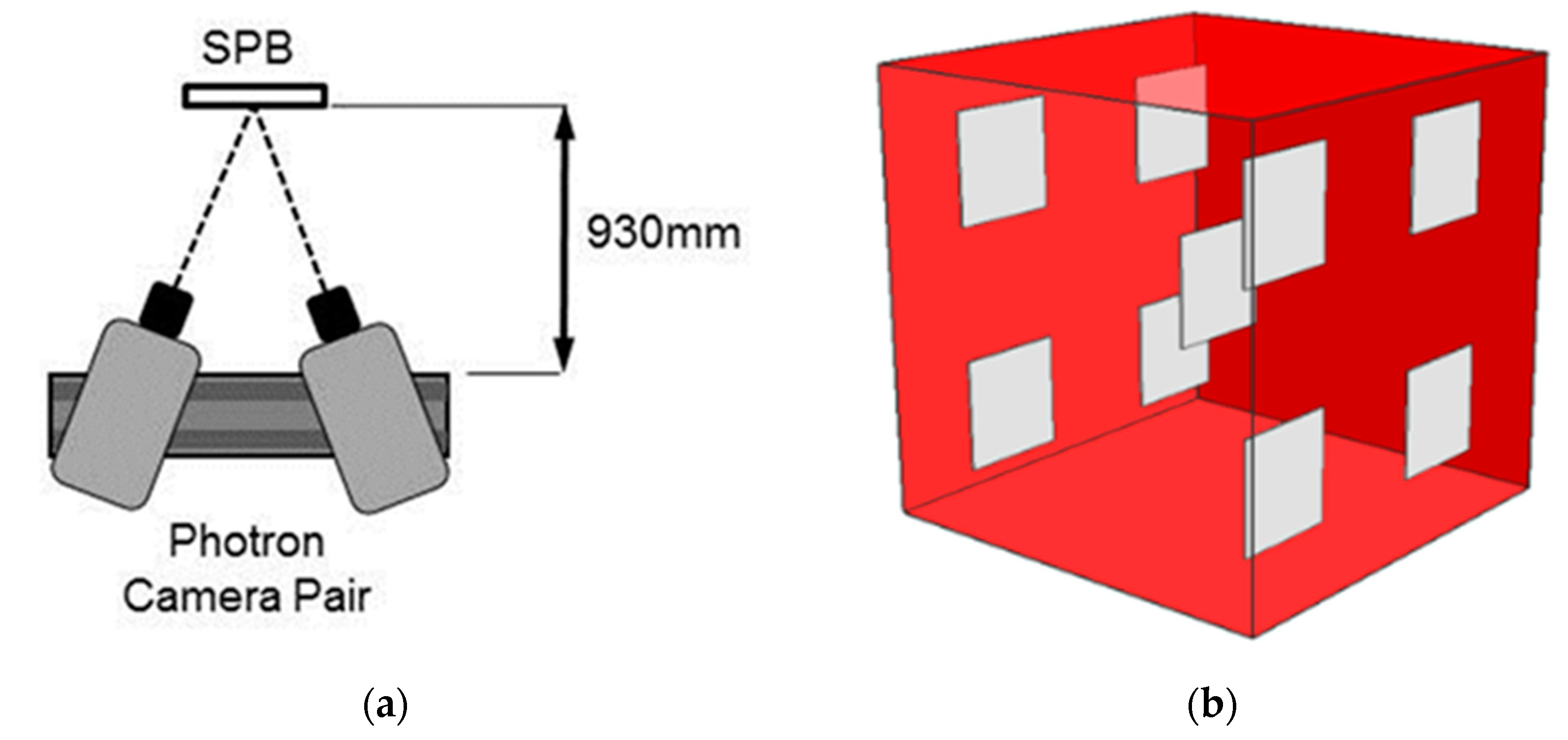
The Photron cameras were set up to achieve the field of view outlined in
Table 1 and aligned to share a common centre point at a distance of 930 mm from the lens. Two ARRILUX 400 ‘Pocket Par’ (Munich, Germany) spotlights were positioned either side of the cameras to achieve appropriate lighting of the measurement volume. Lighting position and intensity were adjusted to achieve sufficient, uniform image contrast, comparable across both cameras when configured with a lens aperture of f16 and a camera shutter speed of 1/10,000 s. System calibration was completed in line with the manufacturer’s guidelines. The SPB panels were mounted on a tripod at the centre of the camera views, as shown in
Figure 3a, and sequential images of each deformation stage were captured by changing the SPB. SPBs were only placed in front of lights for short periods of time so as to minimize any effects of humidity and heating of the pattern boards. To determine if the accuracy was affected by the position within the measurement volume, the test was repeated with the SPBs placed at the locations illustrated in
Figure 3b.
The pattern was positioned approximately parallel to the camera image plane; as a 3D system was being used, more precise alignment was not deemed necessary. Recorded images were imported into the ARAMIS software and processed with a square subset size of 20 × 20 pixels and a computational step size of 13 pixels.
2.8. Data Analysis
DIC is a full-field measurement generating a large number of data points and measurement calibration is thus not simply a task of comparing two values. An evaluation of the measurement accuracy was achieved by considering distributions of measurements and not individual values. Measurement accuracy was defined by the distribution of measurement error: the difference between deformation measurements and the SPB calibration deformation (from
Table 3). An Anderson–Darling (A–D) statistical test was employed to test whether the measurement error data for each stage was normally distributed, with the null hypothesis rejected at a significance level of 5%.
A comparison of the error distributions from different measurements allowed the effect of position within the measurement volume on measurement accuracy to be established. A comparison of distributions was conducted using a two-sample Kolmogorov–Smirnov (K–S) test; a non-parametric test that compares the cumulative distributions of two data sets, testing the probability that the two data sets are sampled from the same distribution. A p-value is calculated from the maximum difference between the cumulative distributions (K–S statistic) and the sample size. The p-value gives the probability that if the two data sets were randomly sampled from the same population, the distributions would be as far apart as observed. The smaller the p-value, the more likely data sets are from populations with different distributions; conversely, the larger the p-value, the more likely data sets are from populations with the same distributions.
The null hypothesis that the data sets were drawn from populations with the same distribution was rejected for p-values equal to or below a 5% level of significance. If the null hypothesis was not rejected, it could then be concluded that the measured distributions have the same underlying distribution, and therefore, position in the volume did not affect the measurement accuracy.
3. Results
An example of a measured strain distribution is illustrated in
Figure 4 for the 30% deformation stage. The measurement accuracy results for all deformation stages are presented in
Table 4, which indicates that the measured mean was very close to the calibrated mean for each deformation stage, with similar standard deviation values. The
p-values from the A–D tests (
Table 4) show that the null hypothesis was accepted for all deformation stages, meaning the errors measured for each stage could be assumed to be normally distributed.
In a normal distribution, 95% of the deformation error measurements at each stage should fall within two standard deviations of the mean. Using this theory, the system measurement accuracy was calculated and the results are shown in
Table 5. The results for the measurement accuracy are relatively consistent across all deformation stages, with the mean error being close to zero and within a ±0.5% strain at a 95% confidence interval.
Measurement error distributions from the 50% deformation stage were used to compare measurements from nine positions within the calibrated measurement volume. The statistical analysis (
Table 6) shows that for positions at the extremities of the volume, when compared with the deformation occurring at the center, the null hypothesis was not rejected and, consequently, it could be assumed that all measurements were drawn from the same distribution. These results indicate that all measurements made were comparable and, therefore, measurement accuracy was unaffected by position within the volume.
4. Discussion
The aim of this paper was to develop an experimental method to enable a traceable measurement calibration to be established for a complete DIC system in a real-world environment. A synthetic speckle pattern, artificially deformed and printed onto speckle pattern boards, was deemed the most suitable approach as speckle characteristics could be controlled and large deformations could be studied.
Optical measurements of the printed boards indicated that the patterns were slightly longer than designed by approximately 0.1–0.2 mm. Errors in identifying the edges of patterns and line features using the OMM were ruled out as the main cause as they were found to be an order of magnitude smaller at ±0.026 mm. The error was found to be evenly distributed across the pattern and relatively consistent over multiple boards and is therefore likely to be related to the printer. By performing a traceable calibration on the actual printed length, this printing error was accounted for in the final DIC system evaluation.
Calibration of the GOM DIC system revealed minimal systematic error. The majority of the measurement error (±0.4% strain) was a result of the distribution of random errors across the full-field measurement. Unfortunately, it is not possible to compare these calibration values to other published work as full-field calibrations of large deformations have not been published to date. However, the measured errors are comparable in magnitude to those determined by Haddadi [
3] using the rigid-body motion of an undeformed sample to determine the measurement error. GOM, the manufacturer of the DIC system, quote an accuracy of strain measurement up to 0.01% strain [
24], but there is no disclosure of the set-up and parameters that should be used to achieve this value or whether this is a best case scenario.
The acceptability of the calibration achieved is very much dependent upon the application of the DIC system and will differ between applications, but is certainly encouraging for those interested in larger deformations. Improvements in the calibration can be achieved, as approximately one quarter of the total measurement error is a result of the edge detection error introduced as part of the material measure calibration. Reducing this error would improve the calibration results for each deformation stage. This could be achieved through utilizing a higher print resolution or a change in printing substrate to reduce ink bleeding.
A limitation of the proposed methodology is that it only considers planar deformations, whereas in real-world applications, deformations are much more complex. Simplification is a necessary first step for controlling the uniformity and intensity of strain fields and calibrating the material measure. Whilst an ideal material measure would include both in- and out-of-plane deformations, this presents significant challenges. Advances in 3D printing may subsequently enable more complex material measures to be created in the future, but, in the meantime, the proposed approach advances further the recommendations in the latest guide to good practice [
10] and will be sufficient for most DIC practitioners wishing to establish a baseline measure of uncertainty.
The advantage of the developed calibration methodology is that it is a simple approach, and the SPBs are cheap and easy to produce and can be adjusted to match the requirements of a particular user or application. The material measure design could be further developed to include more complex planar deformations, for example, the inclusion of strain gradients or multi-axial planar strains and for larger overall deformations. Access to metrology facilities is required to calibrate the material measure, but this is necessary if the calibration is to be traceable.
The approach could be exploited in a number of different ways to understand the performance of 3D-DIC measurement techniques. The most obvious is in the benchmarking and comparison of DIC system performance. Having a traceable material measure would allow particular measurement variables to be isolated and its effect on the measurement accuracy at different deformation stages to be ascertained; for example, lens types or computational parameters. This would support the development of methodologies and set-ups, as well as promote a meaningful analysis of DIC results.

 ,
, 


