Analytical Study of Reinforced Concrete Beams Tested under Quasi-Static and Impact Loadings

1
Department of Civil Engineering, Australian College of Kuwait, P.O. Box 1411, Safat 13015, Kuwait
2
Department of Computational Science and Engineering, North Carolina A&T State University, 1601 E. Market Street, Greensboro, NC 27411, USA
*
Author to whom correspondence should be addressed.
Appl. Sci. 2019, 9(14), 2838; https://doi.org/10.3390/app9142838
Submission received: 28 May 2019
/
Revised: 12 July 2019
/
Accepted: 13 July 2019
/
Published: 16 July 2019
(This article belongs to the Special Issue Fatigue and Fracture of Non-metallic Materials and Structures)
Abstract
:During dynamic events (such as impact forces), structures fail to absorb the incoming energy and catastrophic collapse may occur. Impact and quasi-static tests were carried out on reinforced concrete beams with and without externally bounded sprayed and fabric glass fiber-reinforced polymers. For impact loading, a fully instrumented drop-weight impact machine with a capacity of 14.5 kJ was used. The drop height and loading rate were varied. The load-carrying capacity of reinforced concrete beams under impact loading was obtained using instrumented anvil supports (by summing the support reactions). In quasi-static loading conditions, the beams were tested in three-point loading using a Baldwin Universal Testing Machine. ABAQUS FEA software was used to model some of the tested reinforced concrete beams. It was shown that the stiffness of reinforced concrete beams decreases with increasing drop height. It was also shown that applying sprayed glass fiber-reinforced polymers (with and without mechanical stiffeners) and fabric glass fiber-reinforced polymers on the surface of reinforced concrete beams increased the stiffness. Results obtained from the software analyses were in good agreement with the laboratory test results.
1. Introduction
Concrete structures are subjected to a variety of different loading conditions in day-to-day situations, with the two most ubiquitous of these conditions being quasi-static and impact loadings. With regard to the former, there exists an abundance of research studying the behavior of reinforced concrete (RC) elements under quasi-static load. Conversely, structures such as high-rise buildings are often exposed to damaging impact forces, including the incidental impact of objects, explosions, sudden collapse of cranes, and unregulated motion of heavy machinery. As such, it is also imperative to study the behavior of RC beams under these dynamic loading conditions. To this end, there have been numerous studies conducted on impact loading and its effects on RC structures, with the first known dynamic test being conducted on concrete in 1917 [1]. After years of inactivity, there has been a resurgence in various impact loading experiments performed on concrete over the past 50 years. Researchers such as Atchley and Furr [2], Scott et al. [3], Dilger et al. [4], Mlakar et al. [5], and Soroushian et al. [6] studied the behavior of RC elements under dynamic conditions and discovered that with incremental increases in loading rate, the ultimate stress and strain of concrete increases by about 25%. Moreover, with respect to the compressive strength of RC elements, experiments carried out by Wastein [7], and Malvar and Ross [8] suggest that the compressive strength of concrete under dynamic loads increased by 85–100%. However, the existing literature on the bending capacity of RC beams in response to impact loading remains comparatively scarce. Bertero et al. conducted experiments on simply supported RC beams [9] and noted that the flexural capacity and rigidity of RC beams show an incremental increase at high rates of strain. Similarly, Wakabayashi et al. [10] ran dynamic experiments on beams under strain rates of 0.001 s−1 and discovered that the loading capacity of beams increased by 30% in high strain rates. Comparable experiments have also been carried out by Fujikake et al. [11] to experimentally and analytically evaluate the effect of hammer height and longitudinal reinforcement on the behavior of RC beams, using a mass-spring damper system to simulate the impact response. Furthermore, Pham and Hao [12] performed an accurate numerical simulation (less than 12% average absolute error) using an artificial neural network to predict the response of RC beams to impact loading, with concrete compressive strength, hammer velocity, and mass of hammer being considered as variables. Another important variable—namely, contact stiffness—was studied experimentally and numerically by Pham et al. [13], with results indicating that this variable can significantly influence the peak of load–displacement diagram. Moreover, contact stiffness significantly influenced the bending moment and shear force of the RC beams.
Given the advancing age of RC structures, especially those in developed countries, the importance of using advanced materials—such as fiber-reinforced polymers (FRP)—for rehabilitation purposes encompassing both quasi-static and impact loadings should be emphasized. The use of externally bonded FRP as a strengthening technique for RC structures has gained popularity over the past three decades, with a notable surge in its use being observed in recent years. As such, it is necessary to study the behavior of FRP-strengthened RC elements under the aforementioned loading conditions. With respect to quasi-static loading, there has been an increasing trend in the number of studies conducted in recent years [14,15], establishing the role of externally bonded FRP in augmenting the load-carrying capacity of RC elements. On the other hand, researchers have found that the behavior of RC elements strengthened by externally bonded FRP under impact loading conditions is slightly different compared to that under quasi-static loading, with the significance of the correlation between effective FRP-concrete bonding and performance under load being highlighted [16,17,18,19,20,21].
Considering the existing body of literature, there exists the possibility of further development pertaining to the analytical study of RC beams—specifically, those tested under impact loading, as well as those strengthened by means of sprayed glass fiber-reinforced polymer (GFRP) under quasi-static loading. This paper will attempt to develop upon these topics in order to illuminate the behavior of RC beams treated with sprayed GFRP under quasi-static loading conditions. Greater insight into the use of sprayed GFRP in strengthening RC elements affords several noteworthy advantages over externally bonded fabric FRP, including ease of implementation, cost reduction, and time efficiency. As such, the novelty of this paper lies in two primary domains—the finite element modeling of RC beams strengthened for shear by sprayed GFRP, which remains an understudied area of research, in addition to the presence of mechanical fasteners (i.e., through bolts) in associated modeling schemes.
2. Materials and Methods
A total of 17 RC beams were tested in this study and the experimental results were evaluated using ABAQUS software. Nine RC beams were tested under quasi-static loading including two control and seven retrofitted beams. The other eight beams were used to study the behavior of RC beams under impact loading. Different retrofitting schemes using sprayed GFRP (with and without mechanical fasteners) were employed for shear strengthening of the RC beams tested under quasi-static loading. Fabric GFRP was employed for flexural strengthening. Samples previously experimented in Soleimani’s doctoral dissertation [22] were employed for the modeling and analysis of the behavior of RC beams under quasi-static and impact loads. Table 1, Table 2 and Table 3 show the characteristics of RC beams as well as the properties of sprayed GFRP containing randomly distributed chopped fibers and unidirectional fabric GFRP.
2.1. Quasi-Static Loading
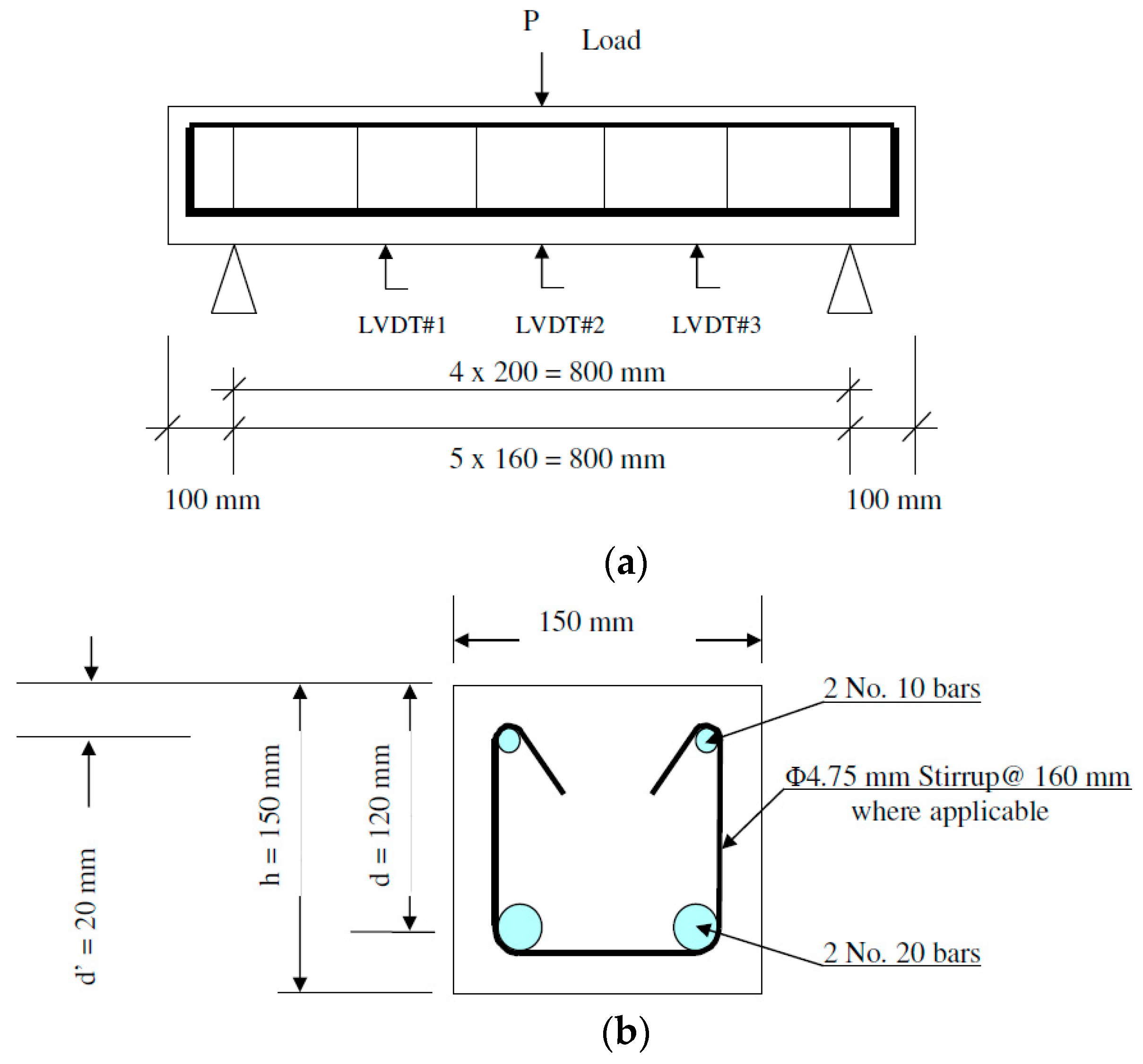
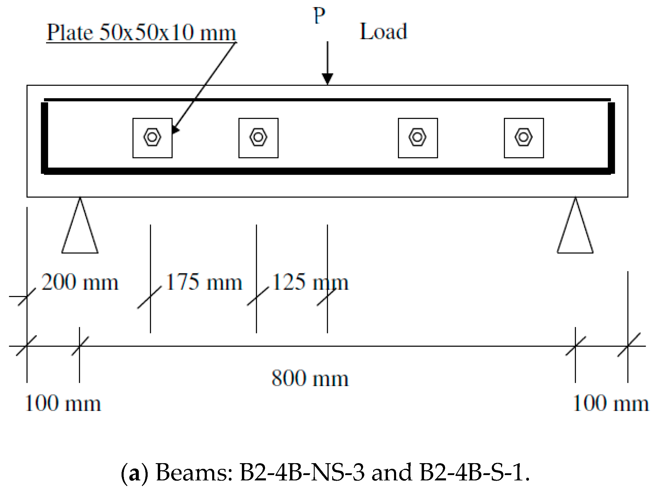
Nine beams (with and without stirrups) were tested using three-point loading under quasi-static condition using a 400 kip Baldwin Universal Testing Machine. The bending capacity of these beams is higher than their shear capacity, meaning that the failure will always be in shear. Two beams (C-NS and C-S-2) were tested as control samples without shear strengthening. The rest were strengthened for shear using sprayed GFRP to evaluate the effectiveness in increasing the shear capacity of the beams. Dimensions and reinforcement details of the beams tested under quasi-static loading are shown in Figure 1. Three Linear Variable Differential Transformers (LVDT) were used to measure the displacement of the beams during testing, as shown in Figure 1. Various parameters, such as the presence of stirrups and through-bolts as mechanical fasteners, were considered as shown in Figure 2. Details of these beams are tabulated in Table 4.
2.2. Impact Loading
A drop weight impact machine with a capacity of 14.5 kJ was used, as shown in Figure 3. A mass of 591 kg (including the striking tup) can be dropped from as high as 2.5 m. During a test, the hammer is raised to a certain height above the specimen using a hoist and chain system. At this position, air brakes are applied on the steel guide rails to release the chain from the hammer. By releasing the breaks, the hammer falls and strikes the specimen. Instrumented anvil supports were used to record the bending loads during the impact [22,23,24].
Dimensions and reinforcement details of the beams tested under impact loading are shown in Figure 4. Enough stirrups were provided to make sure that the beam would fail under bending. Two beams (BS and BS-GFRP) were tested under quasi-static loading and the rest under impact loading with various impact velocities ranging from 2.80 to 6.26 m/s (see Table 5). It is worth mentioning that BS-GFRP and BI-600-GFRP are identical beams strengthened by fabric GFRP. One layer of unidirectional GFRP fabric with a total thickness of about 1.2 mm, length of 750 mm, and width of 150 mm was applied longitudinally on the tension (bottom) side of the beam for flexural strengthening. An extra layer with fibers perpendicular to the fiber direction of the first layer was applied on three sides (two sides and the tension side) for shear strengthening. It is important to note that while the control RC beam (beam “BS”) failed in flexure, the strengthened RC beam failed in shear, indicating that shear strengthening was not as effective as flexural strengthening and perhaps more layers of GFRP were needed to overcome the deficiency of shear strength in these beams. Beam displacement was measured via an accelerometer affixed to the bottom face of the beam in impact experiments (refer to Figure 4).
3. Finite Element Model (FEM)
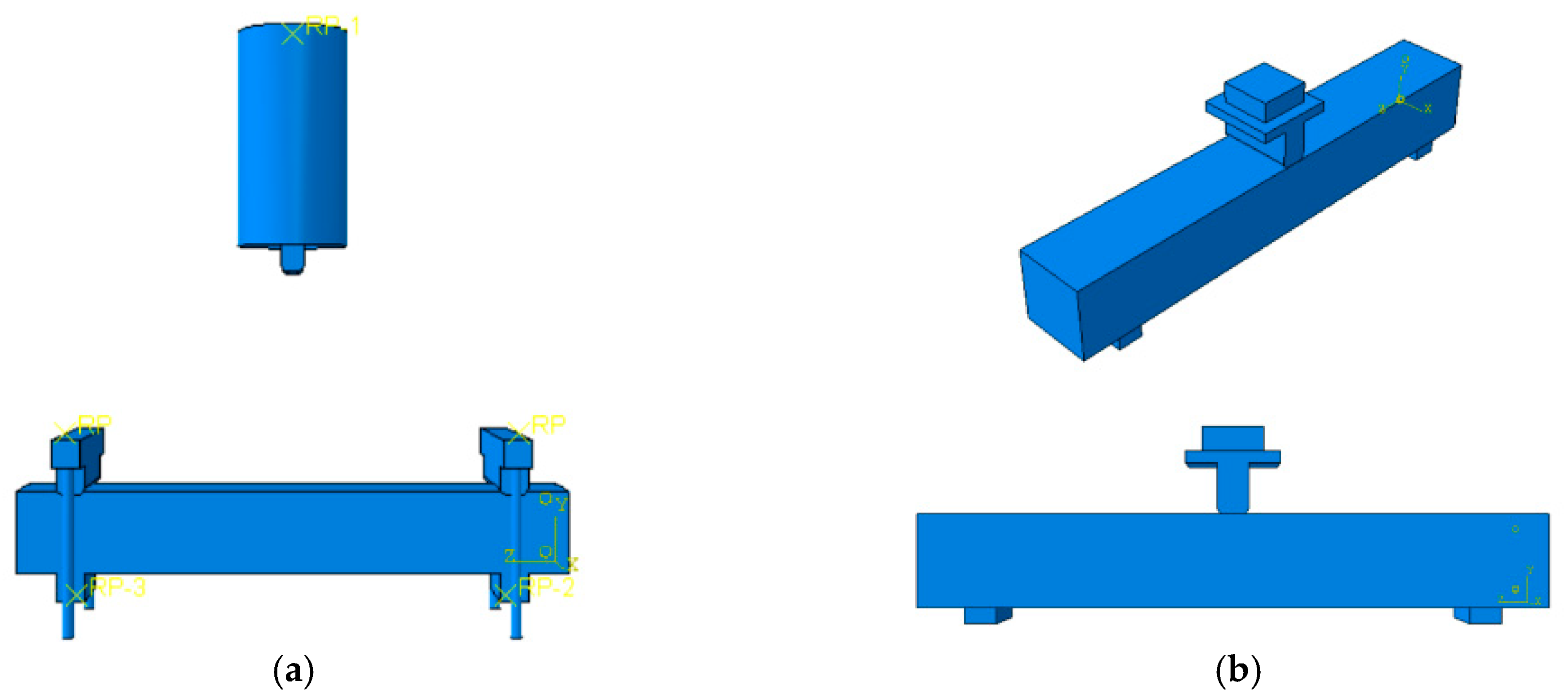
ABAQUS FEA software, a commercially available finite-element analysis program, was used to model the RC beams with and without GFRP strengthening schemes. For concrete modeling, 3D eight-node linear isoparametric elements with reduced integration (C3D8R) were utilized. For longitudinal and transverse bars, truss elements (T3D2) were applied. FRP were modeled using shell elements (S4R). Embedded region coupling was utilized to simulate the bond between longitudinal and transverse reinforcements with concrete. This coupling enables the user to identify one region as the host, and another one as embedded. In this paper, reinforcements represented the embedded region, and concrete was the host region [25]. In order to prevent the scattering of results, coupling restraint was applied. This coupling restraint is formed through a reference point (RP) situated at the center of the support on the bottom of the beam.
For impact, the loading is exerted via a hammer at the mid-span of the beam, and a face-to-face constraint was utilized. Therefore, one could obtain force displacement results at one point with minimal errors. Since the beams were simply supported, U1, U2, and U3 degrees of freedom were set to zero. The arrangement of reinforcing bars, RC beams, supports, and hammer in the software are presented in Figure 5. It is noteworthy that the analyses conducted for these models were quasi-static and dynamic. The BS and BS-GFRP samples shown in Table 5 and all samples mentioned in Table 4 were modeled using quasi-static loading, and BI samples in Table 5 were modeled using dynamic/impact analyses. Dynamic explicit analysis was employed for the impact tests, while dynamic implicit analysis was used for quasi-static analyses. To simulate the behavior of steel reinforcing bars in ABAQUS under a high strain rate, a linear kinematic hardening model was used [25]. In order to model the behavior of confined concrete, a concrete damage plasticity (CDP) model was utilized based on the work of Sayyar Roudsari et al. [26].
4. Results and Discussion
Load vs. mid-span displacement curves from laboratory experiments (EXP) and finite element models (FEM) in ABAQUS are illustrated in Figure 6, Figure 7, Figure 8, Figure 9, Figure 10, Figure 11, Figure 12, Figure 13, Figure 14, Figure 15, Figure 16, Figure 17, Figure 18, Figure 19, Figure 20, Figure 21 and Figure 22.
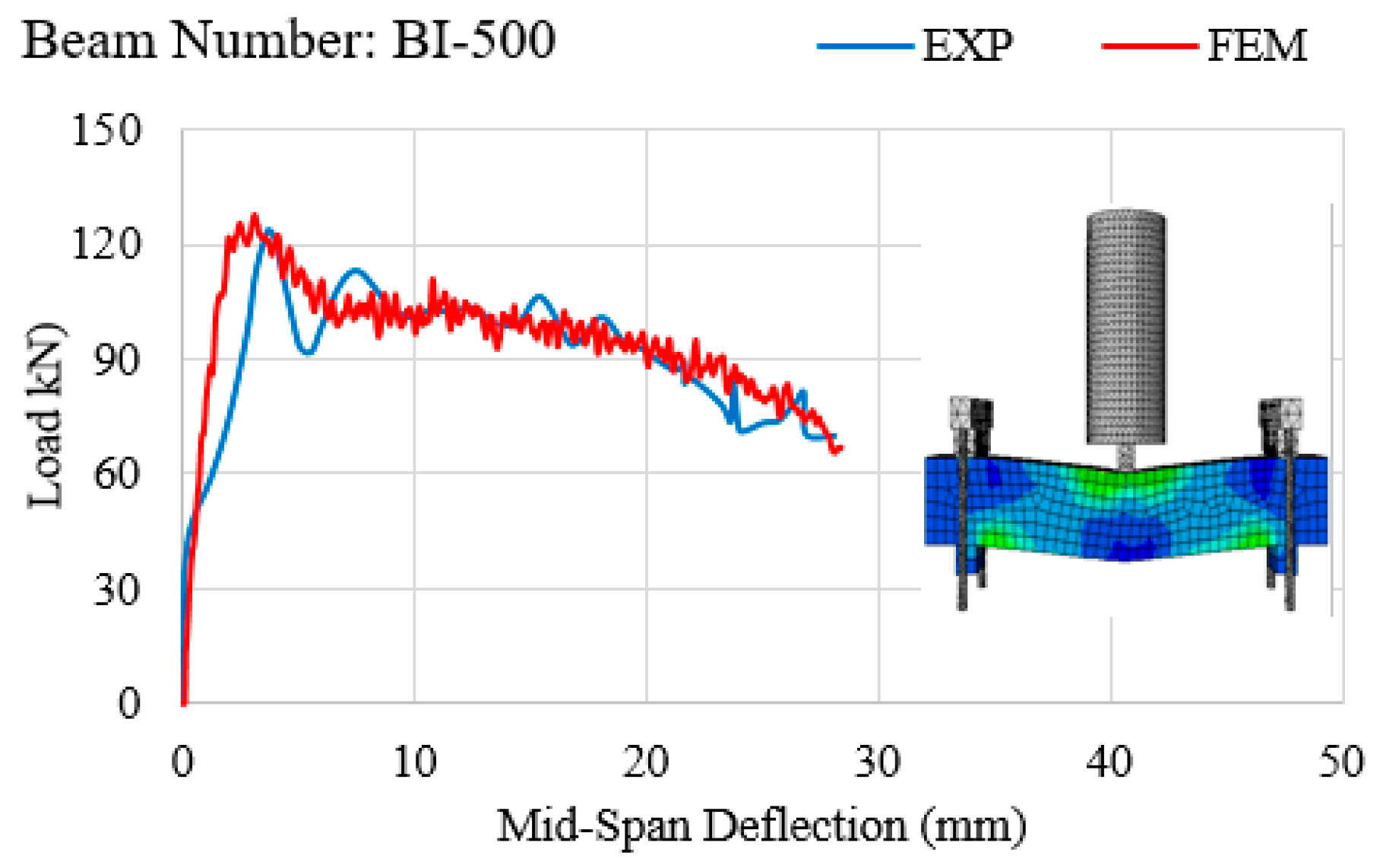
Beams in Figure 6, Figure 7, Figure 8, Figure 9, Figure 10, Figure 11, Figure 12 and Figure 13 have the same reinforcement details as those shown in Figure 4. Figure 6 shows the load vs. mid-span displacement curve of the RC beam under quasi-static loading, and Figure 7, Figure 8, Figure 9, Figure 10 and Figure 11 demonstrate similar curves for RC beams tested under impact loading. Results obtained for RC beams strengthened with fabric GFRP under quasi-static and impacts loading are illustrated in Figure 12 and Figure 13, respectively. Results from the finite element models prove tangible correspondence with those of the laboratory experiments, so much so that the maximum difference between the laboratory and software results was found to be no more than 20% (ranging between 0.1% for BS in Figure 6, and 20% for BI-400 in Figure 7. It is worth mentioning that the difference between the laboratory and software results are negligible except for BI-400. It can be inferred that a minimum drop height of around 500 mm is required to make the RC beam fail, which was not met for BI-400 as its drop height was only 400 mm. This is the most probable cause of the 20% difference. Comparing the results, the beam BS-GFRP that is strengthened with GFRP and tested under quasi-static loading showed a 29.3% increase in load-carrying capacity in the laboratory experiment and a 30.0% increase in the software model.
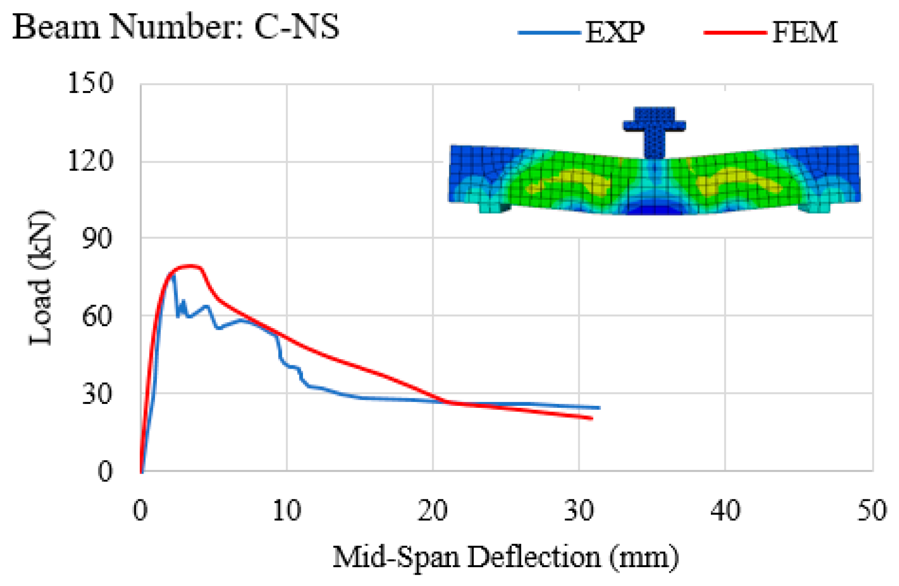
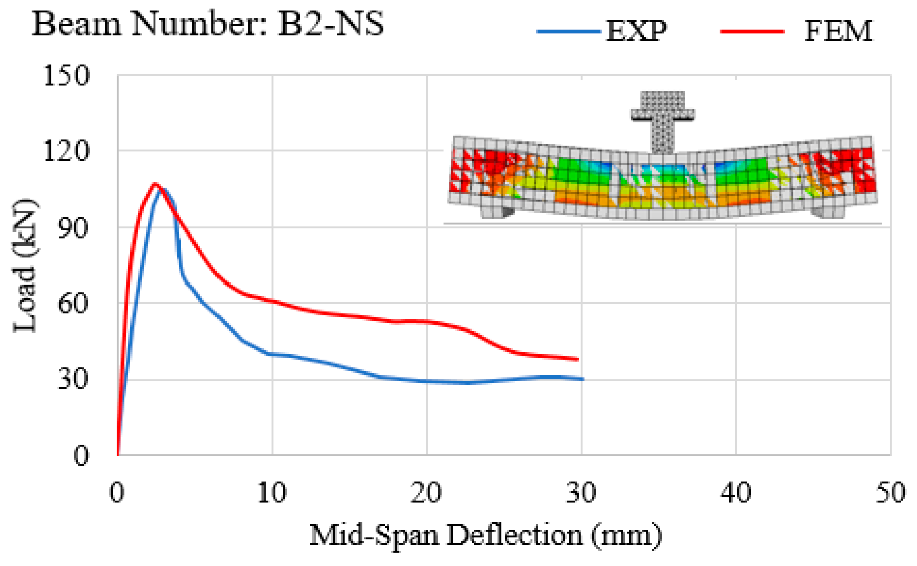
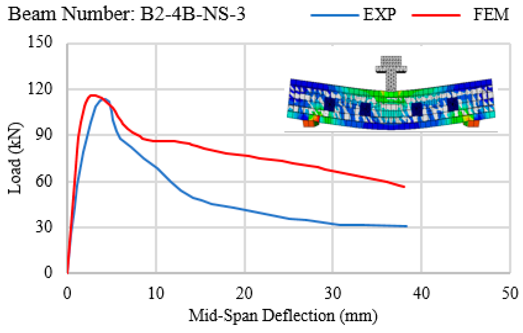
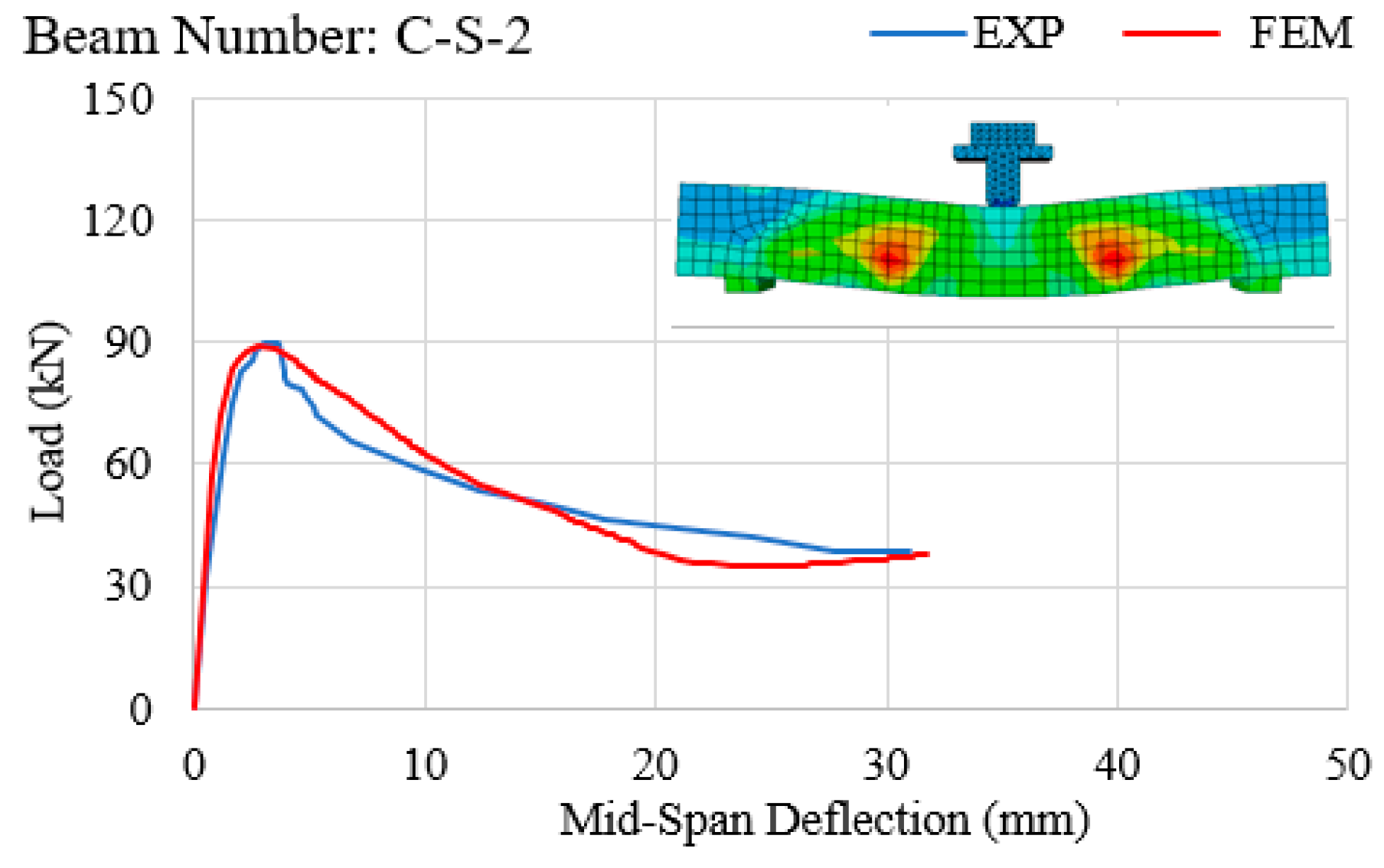
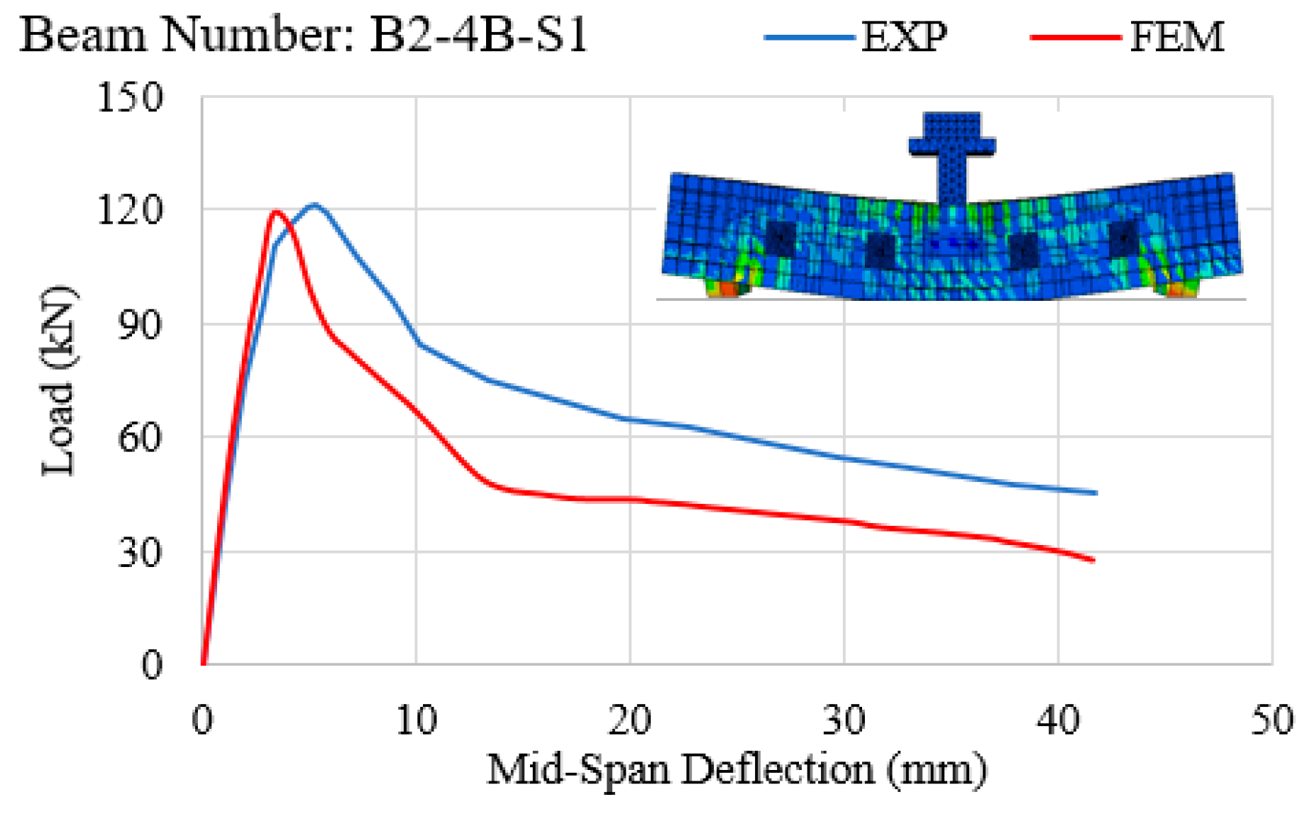
Figure 14, Figure 15, Figure 16, Figure 17, Figure 18, Figure 19, Figure 20, Figure 21 and Figure 22 present the load vs. mid-span displacement curves under quasi-static loading based on Table 4. Results from the FEM analysis are in very good agreement with the experimental results, with a maximum difference of 5%. In effect, the FEM analysis is seen to accurately predict the rate of load-carrying capacity vs. displacement before and after the maximum load.
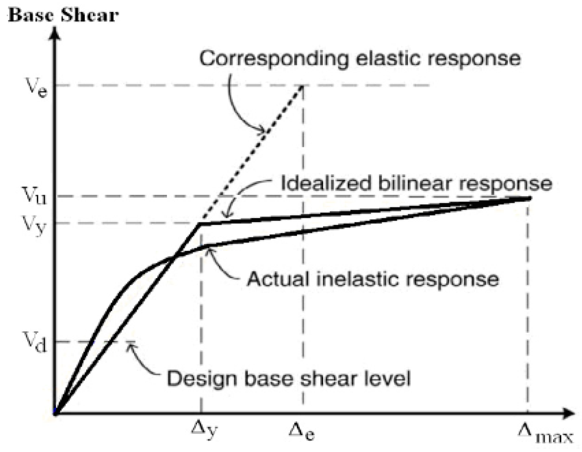
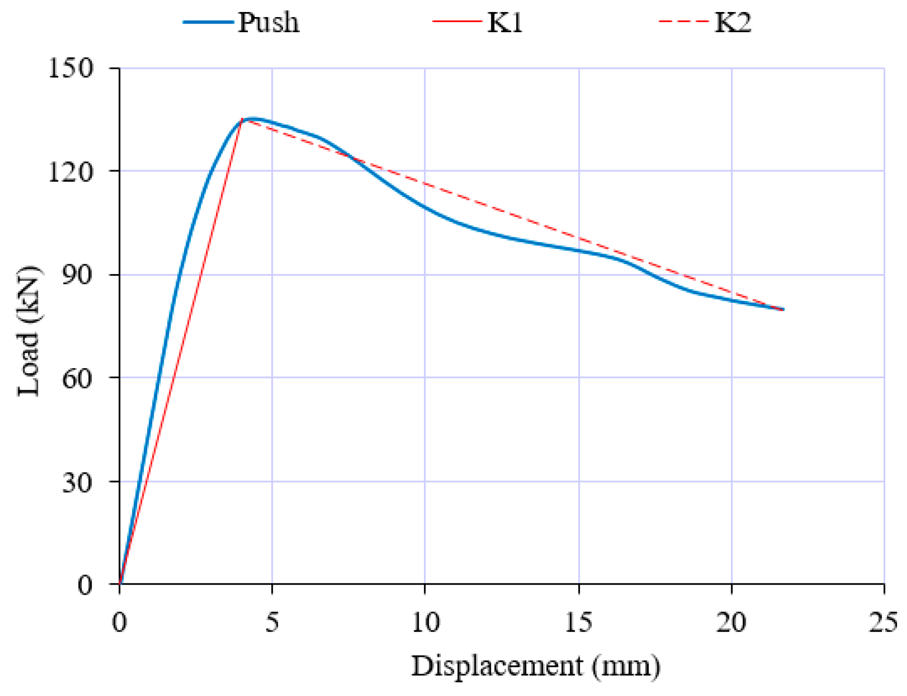
The load–displacement curve can be idealized by a bilinear graph similar to Figure 23. The stiffness of the beam can then be calculated using Equation (1): [27]
Stiffness = Vy/∆y.
The load–displacement curve of C-NS beam is idealized in Figure 24, and the stiffness was calculated. Following the same procedure, the stiffness of all beams was calculated, and the values are illustrated in Figure 25 and Figure 26.
As shown in Figure 25, it is apparent that the stiffness of the beam under impact loading increased with respect to its stiffness under quasi-static loading. Also, increasing the impact velocity reduced the stiffness (the stiffness increased from BS to BI-400 and then decreased from BI-400 to BI-2000). The same trend was observed in FEM as well as experimental results. Fabric GFRP increased the stiffness of the beam under both quasi-static and impact loadings. The increase in stiffness under impact loading was more apparent in BS and BS-GFRP compared to BI-600 and BI-600-GFRP. One can conclude that fabric GFRP is quite effective in enhancing the stiffness of an RC beam under impact loading.
As shown in Figure 26, sprayed GFRP is more effective than steel stirrups in enhancing the stiffness of the beam (C-NS vs. C-S-2 as well as C-NS vs. B2-NS, B2-4B-NS-3, and B2-6B-NS-1). Shear strengthening of RC beams using sprayed FRP effectively increased the stiffness of the beam, either with or without stirrups. This was apparent from the results obtained from both FEM and experiments. Through-bolts are more effective in increasing the stiffness when they are employed for strengthening of the beams with steel stirrups. The thickness of the sprayed GFRP plays a role in increasing the stiffness (4 mm thickness is more effective than 3.5 mm, even if the number of through-bolts is greater in the thinner layer of sprayed FRP).
Comparing Figure 25 and Figure 26, one can conclude that the FEM are more successful in predicting the stiffness of RC beams under quasi-static loading. Tanarslan et. al. [28] tested RC beams strengthened by prefabricated ultra-high-performance fiber RC laminates and also reported the increase of stiffness.
5. Conclusions
Based on the results obtained from the experiment and verified by the finite element analyses, the following conclusions can be drawn from this study:
- Load vs. mid-span displacement curves obtained from finite element models generated by ABAQUS software, for both quasi-static and impact loadings, suggest close correspondence with laboratory results.
- In quasi-static loading on an RC beam (Figure 6) with an adequate number of stirrups, both ABAQUS software and laboratory results verified that the stress in longitudinal tension reinforcements exceeded the yield stress of steel, and the load-carrying capacity of the beam increased subsequent to the yield of tensile steel. This implies that the failure of the RC beam presented in Figure 6 is flexural.
- In all experiments conducted on RC beams under impact loading (Figure 7, Figure 8, Figure 9, Figure 10 and Figure 11 and Figure 13), the beams failed in shear as opposed to flexure. Thus, there is a correlation between the application of fabric GFRP and the increased shear strength capacity of RC beams. The RC beams strengthened by fabric GFRP depicted a higher load-carrying capacity in both quasi-static and impact loadings compared to that of non-strengthened RC beams (Figure 7, Figure 9, Figure 12, and Figure 13). Fabric GFRP effectively increased the beam’s stiffness under both quasi-static and impact loadings (Figure 25).
- Although the beam’s stiffness under impact loading is increased as opposed to that under quasi-static loading, stiffness under impact loading will be reduced by increasing impact velocity (Figure 25).
- Sprayed GFRP (with and without through-bolts) increases the beam’s stiffness (Figure 26). The through-bolts are more effective in increasing the beam’s stiffness when some steel stirrups are present.
- Using FEM to predict the stiffness of RC beams was more effective for beams tested under quasi-static conditions as compared to those tested under impact loading.
Considering these results and their implications, this paper has highlighted the possibility of further research with respect to the analytical study of RC beams strengthened by sprayed GFRP under impact loading. Research into this field is not as developed as compared to externally bonded fabric FRP, and it is imperative that this gap be narrowed by future works.
Author Contributions
S.S.R. conducted the finite element analysis and prepared the original draft; S.M.S. supervised the project, checked the results, reviewed and edited the paper.
Funding
This research received no external funding.
Conflicts of Interest
The authors declare no conflict of interest.
References
- Abrams, D.A. Effects of rate of application of load on the compressive strength of concrete. In Proceedings of the American Society for Testing and Materials, Atlantic City, NJ, USA, 26–29 June 1917; Volume 17, Part II. pp. 364–377. [Google Scholar]
- Atchley, B.L.; Furr, H.L. Strength and energy absorption capabilities of plain concrete under dynamic and static loadings. Am. Concr. Inst. J. 1967, 64, 745–756. [Google Scholar]
- Scott, B.D.; Park, R.; Priestley, M.J.N. Stress-strain behaviour of concrete confined by overlapping hoops at low and high strain rates. J. Am. Concr. Inst. 1982, 79, 496–498. [Google Scholar]
- Dilger, W.; Kand, R.; Kowalczyk, R. Ductility of plain and confined concrete under different strain rates. Am. Concr. Inst. J. 1984, 81, 73–81. [Google Scholar]
- Mlakar, P.F.; Vitaya-Udom, K.P.; Cole, R.A. Dynamic tensile-compressive behaviour of concrete. Am. Concr. Inst. J. 1986, 86, 484–491. [Google Scholar]
- Soroushian, P.; Choi, K.-B.; Alhamad, A. Dynamic constitutive behaviour of concrete. Am. Concr. Inst. J. 1986, 83, 251–259. [Google Scholar]
- Watstein, D. Effect of straining rate on the compressive strength and elastic properties of concrete. Am. Concr. Inst. J. 1953, 24, 729–744. [Google Scholar]
- Malvar, L.J.; Ross, C.A. Review of strain rate effects for concrete in tension. Mater. J. 1998, 95, 735–739. [Google Scholar]
- Bertero, V.V.; Rea, D.; Mahin, S.; Atalay, M.B. Rate of loading effects on uncracked and repaired reinforced concrete members. In Proceedings of the 5th World Conference on Earthquake Engineering, Rome, Italy, 25–29 June 1973; Volume II, pp. 1461–1470. [Google Scholar]
- Wakabayashi, M.; Nakamura, T.; Yoshida, N.; Iwai, S.; Watanabe, Y. Dynamic loading effects on the structural performance of concrete and steel materials and beams. In Proceedings of the 7th World Conference on Earthquake Engineering, Istanbul, Turkey, 8–13 September 1980. [Google Scholar]
- Fujikake, K.; Li, B.; Soeun, S. Impact response of reinforced concrete beam and its analytical evaluation. J. Struct. Eng. 2009, 135, 938–950. [Google Scholar] [CrossRef]
- Pham, T.M.; Hao, H. Prediction of the impact force on RC beams from a drop weight. Adv. Struct. Eng. 2016. [Google Scholar] [CrossRef]
- Pham, T.M.; Hao, Y.; Hao, H. Sensitivity of impact behavior of RC beams to contact stiffness. Int. J. Impact Eng. 2017. [Google Scholar] [CrossRef]
- Jabr, A.; El-Ragaby, A.; Ghrib, F. Effect of the fiber type and axial stiffness of FRCM on the flexural strengthening of RC beams. Fibers 2017, 5, 2. [Google Scholar] [CrossRef]
- Peng, H.; Shang, S.; Jin, Y.-J.; Wang, M. Experimental study of reinforced concrete beam with prestressed CFRP plate. Eng. Mech. 2008, 25, 142–151. [Google Scholar]
- White, T.; Soudki, K.; Erki, M. Response of RC beams strengthened with CFRP laminates and subjected to a high rate of loading. J. Compos. Constr. 2001, 5, 153–162. [Google Scholar] [CrossRef]
- Tang, T.; Saadatmanesh, H. Behavior of concrete beams strengthened with fiber-reinforced polymer laminates under impact loading. J. Compos. Constr. 2003, 7, 209–218. [Google Scholar] [CrossRef]
- Tang, T.; Saadatmanesh, H. Analytical and experimental studies of fiber-reinforced polymer strengthened concrete beams under impact loading. ACI Struct. J. 2005, 102, 139–149. [Google Scholar]
- Hamed, E.; Rabinovitch, O. Dynamic behavior of reinforced concrete beams strengthened with composite materials. J. Compos. Constr. 2005, 9, 429–440. [Google Scholar] [CrossRef]
- Pham, T.M.; Hao, H. Impact behavior of FRP-strengthened RC beams without stirrups. J. Compos. Constr. 2016. [Google Scholar] [CrossRef]
- Meola, C.; Boccardi, S.; Carlomagno, G.M. Infrared thermography for inline monitoring of glass/epoxy under impact and quasi-static bending. Appl. Sci. 2018, 8, 301. [Google Scholar] [CrossRef]
- Soleimani, S.M. Sprayed Glass Fiber Reinforced Polymers in Shear Strengthening and Enhancement of Impact Resistance of Reinforced Concrete Beams. Ph.D. Thesis, The University of British Columbia, Vancouver, BC, Canada, 2007. [Google Scholar]
- Soleimani, S.M.; Banthia, N. A novel drop weight impact setup for testing reinforced concrete beams. J. Exp. Tech. 2014, 38, 72–79. [Google Scholar] [CrossRef]
- Soleimani, S.M.; Banthia, N. Reinforced concrete beams under impact loading and influence of a GFRP coating. Int. Rev. Civ. Eng. 2010, 1, 68–77. [Google Scholar]
- ABAQUS Analysis User’s Guide. Available online: http://dsk.ippt.pan.pl/docs/abaqus/v6.13/books/usb/default.htm (accessed on 16 July 2019).
- Sayyar Roudsari, S.; Hamoush, S.A.; Soleimani, S.M.; Madandoust, R. Evaluation of large-size reinforced concrete columns strengthened for axial load using fiber reinforced polymers. Eng. Struct. 2019, 178, 680–693. [Google Scholar] [CrossRef]
- Mahmoudi, M.; Zaree, M. Determination the response modification factors of buckling restrained braced frames. Procedia Eng. 2013, 54, 222–231. [Google Scholar] [CrossRef]
- Tanarslan, M.; Alver, N.; Jahangiri, R.; Yalçınkaya, Ç.; Yazıcı, H. Flexural strengthening of RC beams using UHPFRC laminates: Bonding techniques and rebar addition. Constr. Build. Mater. 2017, 155, 45–55. [Google Scholar] [CrossRef]
Figure 1.
Reinforced concrete (RC) beams tested under quasi-static loading: (a) elevation; (b) cross-section [22].
Figure 1.
Reinforced concrete (RC) beams tested under quasi-static loading: (a) elevation; (b) cross-section [22].

Figure 2.
Bolt configuration of RC beams with sprayed GFRP: (a) four bolts; (b) six bolts; (c) cross-sections with no stirrups; (d) cross-sections with stirrups [22].
Figure 2.
Bolt configuration of RC beams with sprayed GFRP: (a) four bolts; (b) six bolts; (c) cross-sections with no stirrups; (d) cross-sections with stirrups [22].


Figure 3.
Impact machine.

Figure 4.
Elevation and cross-section of RC beams tested under impact loading; (a) elevation; (b) cross-section [22].
Figure 4.
Elevation and cross-section of RC beams tested under impact loading; (a) elevation; (b) cross-section [22].

Figure 5.
RC beam assembly simulations; (a) impact, (b) quasi-static.

Figure 6.
Load vs. mid-span deflection for BS; EXP: experimental; FEM: finite element modeling.

Figure 7.
Load vs. mid-span deflection for BI-400.

Figure 8.
Load vs. mid-span deflection for BI-500.

Figure 9.
Load vs. mid-span deflection for BI-600.

Figure 10.
Load vs. mid-span deflection for BI-1000.

Figure 11.
Load vs. mid-span deflection for BI-2000.

Figure 12.
Load vs. mid-span deflection for BS-GFRP.

Figure 13.
Load vs. mid-span deflection for BI-600-GFRP.

Figure 14.
Load vs. mid-span deflection for C-NS.

Figure 15.
Load vs. mid-span deflection for B2-NS.

Figure 16.
Load vs. mid-span deflection for B2-4B-NS-3.

Figure 17.
Load vs. mid-span deflection for B2-6B-NS-1.

Figure 18.
Load vs. mid-span deflection for C-S-2.

Figure 19.
Load vs. mid-span deflection for B2-S-1.

Figure 20.
Load vs. mid-span deflection for B2-4B-S-1.

Figure 21.
Load vs. mid-span deflection for B2-6B-S-1.

Figure 22.
Load vs. mid-span deflection for B3-S-2.

Figure 23.
Load vs. displacement bilinear graph [27].
Figure 23.
Load vs. displacement bilinear graph [27].

Figure 24.
Bilinear graph for C-NS beam.

Figure 25.
Comparison of beam stiffness under impact loading: finite element model (FEM) vs. experimental results.
Figure 25.
Comparison of beam stiffness under impact loading: finite element model (FEM) vs. experimental results.

Figure 26.
Comparison of beam stiffness under quasi-static loading: FEM vs. experimental results.


Table 1.
Characteristics of reinforced concrete beams.
| Parameter | Definition | Value | Unit |
|---|---|---|---|
| f’c | Specified compressive strength of concrete | 44 | MPa |
| fy | Specified yield strength of tension reinforcement | M-10: 474; M-20: 440 | MPa |
| fys | Specified yield strength of shear reinforcement | 600 | MPa |
| fu | Specified ultimate strength of tension reinforcement | M-10: 720; M-20: 695 | MPa |
| fus | Specified ultimate strength of shear reinforcement | 622 | MPa |
| As | Area of reinforcement (M-10 and M-20 for tension and ϕ4.75 for shear) | M-10: 100; M-20: 300; ϕ4.75: 18.1 | mm2 |
Table 2.
Sprayed glass fiber-reinforced polymer (GFRP) properties.
| Properties | Value | Unit |
|---|---|---|
| Ultimate tensile strength | 69 | MPa |
| Tensile modulus | 14 | GPa |
| Ultimate rupture strain | 0.63 | % |
Table 3.
Fabric GFRP properties.
| Properties | Value | Unit |
|---|---|---|
| Ultimate tensile strength | 1517 | MPa |
| Tensile modulus | 72.4 | GPa |
| Ultimate tensile strength per unit width | 0.536 | KN/mm/ply |
| Tensile modulus per unit width | 25.6 | KN/mm/ply |
| Ultimate rupture strain | 2.1 | % |
Table 4.
Designations of RC beams tested under quasi-static loading as shown in Figure 1 and Figure 2.
| Beam’s Designation | Stirrups? | Sprayed GFRP on Two Sides or Three? | Width of Sprayed GFRP on the Sides (mm) | Thickness of Sprayed GFRP (mm) | No. of Through Bolts as Mechanical Fastener |
|---|---|---|---|---|---|
| C-NS | No | N/A | N/A | N/A | N/A |
| B2-NS | No | 2 | 100 | 4 | N/A |
| B2-4B-NS-3 | No | 2 | 100 | 4 | 4 |
| B2-6B-NS-1 | No | 2 | 100 | 3.5 | 6 |
| C-S-2 | Yes | N/A | N/A | N/A | N/A |
| B2-S-1 | Yes | 2 | 150 | 3.5 | N/A |
| B2-4B-S-1 | Yes | 2 | 150 | 3.5 | 4 |
| B2-6B-S-1 | Yes | 2 | 150 | 4 | 6 |
| B3-S-2 | Yes | 3 | 150 | 4 | N/A |
Table 5.
Designations and details of RC beams tested under impact loading as shown in Figure 4.
Table 5.
Designations and details of RC beams tested under impact loading as shown in Figure 4.
| Beam’s Designation | Quasi-Static or Impact? | Drop Height (mm) | Impact Velocity (m/s) |
|---|---|---|---|
| BS | Quasi-static (control) | NA | NA |
| BI-400 | Impact | 400 | 2.8 |
| BI-500 | Impact | 500 | 3.13 |
| BI-600 | Impact | 600 | 3.43 |
| BI-1000 | Impact | 1000 | 4.43 |
| BI-2000 | Impact | 2000 | 6.26 |
| BS-GFRP | Quasi-static (control) | NA | NA |
| BI-600-GFRP | Impact | 600 | 3.43 |
© 2019 by the authors. Licensee MDPI, Basel, Switzerland. This article is an open access article distributed under the terms and conditions of the Creative Commons Attribution (CC BY) license (http://creativecommons.org/licenses/by/4.0/).
Share and Cite
MDPI and ACS Style
Soleimani, S.M.; Sayyar Roudsari, S. Analytical Study of Reinforced Concrete Beams Tested under Quasi-Static and Impact Loadings. Appl. Sci. 2019, 9, 2838. https://doi.org/10.3390/app9142838
AMA Style
Soleimani SM, Sayyar Roudsari S. Analytical Study of Reinforced Concrete Beams Tested under Quasi-Static and Impact Loadings. Applied Sciences. 2019; 9(14):2838. https://doi.org/10.3390/app9142838
Chicago/Turabian StyleSoleimani, Sayed Mohamad, and Sajjad Sayyar Roudsari. 2019. "Analytical Study of Reinforced Concrete Beams Tested under Quasi-Static and Impact Loadings" Applied Sciences 9, no. 14: 2838. https://doi.org/10.3390/app9142838
Note that from the first issue of 2016, this journal uses article numbers instead of page numbers. See further details here.