A Damage Model for Concrete under Fatigue Loading


School of Civil Engineering & National Engineering Laboratory for High Speed Railway Construction & Engineering Technology Research Center for Prefabricated Construction Industrialization of Hunan Province, Central South University, 68 South Shaoshan Road, Changsha 410075, China
*
Author to whom correspondence should be addressed.
Appl. Sci. 2019, 9(13), 2768; https://doi.org/10.3390/app9132768
Submission received: 3 June 2019
/
Revised: 25 June 2019
/
Accepted: 25 June 2019
/
Published: 9 July 2019
(This article belongs to the Special Issue Fatigue and Fracture of Non-metallic Materials and Structures)
Abstract
:For concrete, fatigue is an essential mechanical behavior. Concrete structures subjected to fatigue loads usually experience a progressive degradation/damage process and even an abrupt failure. However, in the literature, certain essential damage behaviors are not well considered in the study of the mechanism for fatigue behaviors such as the development of irreversible/residual strains. In this work, a damage model with the concept of mode-II microcracks on the crack face and nearby areas contributing to the development of irreversible strains was proposed. By using the micromechanics method, a micro-cell-based damage model under multi-axial loading was introduced to understand the damage behaviors for concrete. By a thermodynamic interpretation of the damage behaviors, a novel fatigue damage variable (irreversible deformation fatigue damage variable) was defined. This variable is able to describe irreversible strains generated by both mode-II microcracks and irreversible frictional sliding. The proposed model considered both elastic and irreversible deformation fatigue damages. It is found that the prediction by the proposed model of cyclic creep, stiffness degradation and post-fatigue stress-strain relationship of concrete agrees well with experimental results.
1. Introduction
Fatigue is an essential mechanical behavior of concrete. In real life, a large number of concrete structures are subjected to fatigue loads, e.g., off-shore structures and bridges. Although the subjected fatigue loads are lower than the relevant materials’ original strength, these structures experience a progressive degradation and subsequently an abrupt failure. In order to investigate these fatigue behaviors, several methods (e.g., fatigue life concepts [1,2,3,4] and phenomenological models [5,6,7,8]) were developed by researchers and were widely applied in structural engineering. However, during the designing and analysis of structures, these methods [1,2,3,4,5,6,7,8] are only limited to describing the fatigue behaviors at phenomenological and empirical levels without a comprehensive understanding and explanation of the internal mechanism for damage behaviors of concrete under fatigue loading.
The complex constitution of concrete results in a sophisticated damage evolution process during material under loading. Specifically, in the material, the arbitrary distribution of initial defects causes the localization of stresses, which further produce the complex evolution process of damage. Experimental studies [9,10,11,12,13,14] have been conducted to understand the damage mechanism referring to concrete under fatigue loading. In detail, some experimental results showed that local stresses near the defect cause the heterogeneous crack openings perpendicular to tensile loading, i.e., mode-I cracks. The mode-I cracks were well studied in a number of research papers [9,10,11,12]. In addition, [13] applied X-ray techniques to study the microcrack mechanism of concrete, and it was found that microcracks parallel to tensile loading (mode-II cracks) can occur even under pure global axial loading. Reference [14] found the mode-II cracks are able to create irreversible strains due to local stresses. Furthermore, a series of relevant comprehensive works have been conducted by researchers in the solid mechanical field for more than a decade [15,16,17,18,19,20,21,22,23].
Moreover, the mechanism of the development for irreversible/residual strains in concrete under fatigue loading have been studied throughout several methods [6,12,24,25,26,27,28,29,30,31,32,33,34,35,36,37,38,39,40,41,42,43,44,45,46,47,48,49]. Concretely, on one hand, based on the micro-mechanics method [6,12,24,25,26,27,28,29,30,31,32,33,34,35,36,37,38,39,40], it is concluded that irreversible strains are produced by a series of types of cracking, which are distinguished as follows: (I) for a compressive case, the transversely propagating crushing band [24,25], the axial wedge-splitting cracks at hard inclusions in hardened cement paste [26], the interface cracks at inclusions [6], the pore-opening axial cracks [27,28], and the inclined wing-tipped frictional cracks (i.e., wing cracks) [29,30,31,32,33]; (II) for a tensile case, the irreversible opening of mode-I cracks due to the locking mechanisms of crack faces [34], the irreversible sliding-like openings of mode-II crack due to the toughness of crack faces [35,36], the irreversible frictional sliding over the crack surface [37,38], the irreversible cracking of the fracture process zone [12,39], and other cracking mechanisms [40]. On the other hand, based on the macro-mechanics method [41,42,43,44,45,46,47,48,49], researchers have rarely considered the comprehensive mechanism of concrete damage, since they are usually focused on the accurate characterization of macroscopic mechanical behaviors.
However, among the above-mentioned literature, certain essential damage behaviors are not well considered in the study of the mechanism for the development of irreversible/residual strains in concrete. Specifically, one type of those damage behaviors is mode-II microcracks, which has attracted the attention of researchers in the field of solids mechanics for decades [15,16,17,18,19,20,21,22,23].
Therefore, it is necessary to develop a continuum damage model for concrete under fatigue loading with the consideration of this damage behavior. In detail, this damage model is able to be established based on the micro-mechanics and continuum damage mechanics. Micro-mechanics enables us to understand damage behavior under multi-axial loading, and the continuum damage mechanics (CDM) method (i.e., a macro-mechanics method) offers us a convenient way to characterize the macro behavior.
This work develops the above-mentioned contributions [6,12,24,25,26,27,28,29,30,31,32,33,34,35,36,37,38,39,40,41,42,43,44,45,46,47,48,49] in two aspects, the description of the micro-mechanism for mode-II microcracks in multi-axial conditions and the thermodynamics-based modeling of damage behaviors in concrete under fatigue loading.
2. Microcrack Mechanism in Concrete under Multi-Axial Loading
In this section, we briefly recall here the main steps of the methodology followed by the literature [22] for the micro-mechanical description of mode-II microcracks. In addition, the random distribution of initial defects in concrete under multi-axial loading was considered in this work.
2.1. The Definition of the Mode-II Microcracks
Mode-II microcracks are the local shear stress-caused by microcracks on the crack face and in the nearby area of the micro-defects and the mode-I crack. This type of crack is different from the mode-I crack and the mode-II crack. The differences can be concluded as follows, the mode-II microcracks are the result of local shear stresses, which is distinguished from tensile stress-caused by the mode-I crack. Additionally, unlike the mode-II crack, mode-II microcracks usually appear on the face and nearby area of the micro-defects and mode-I crack.
2.2. The Causes for the Mode-II Microcracks under Multi-Axial Loading
When the concrete is subjected to a biaxial tensile load, a micro-cell within a representative volume element (RVE) was introduced and is shown in Figure 1. In detail, the stress flow curve becomes concentrated when it approaches the crack tip, and the plane stress on the plane horizontal and vertical to the direction of the crack propagation is able to be described by the normal and shear stress as follows, σh and τh, σv and τv, respectively (Figure 1c). Due to sufficient normal stress σv or stress intensity factor (SIF) KI at the crack tip, the crack will initiate and grow through the direction where the maximum SIF exists (i.e., transverse to the direction of maximum principal tension, Figure 1d–e). Therefore, the crack type, namely the mode-I crack, decreases the effective load area of the micro-cell in the maximum principal tension direction, resulting in the stiffness degradation of the specimen [33,34,35,36,50].
However, mode-II microcracks have not been well considered in modeling concrete under multi-axial stresses in the literature [6,12,22,23,24,25,26,27,28,29,30,31,32,33,34,35,36,37,38,39,40]. Through different approaches, including experimental observations, mechanical analysis and atomic simulations [15,16,17,18,19,20,21], it is validated that the real crack (excepting some pre-existing cracks) in the material is blunt, caused by the appearance of mode-II microcracks.
Specifically, mode-II microcracks are produced by the local shear stresses (i.e., the shear stress τh in Figure 1c and Figure 2a) on the face and nearby area of relevant cracks. In a biaxial tensile load case, the directions of local shear stresses are arbitrary due to the random location of initial defects. It is distinguished from that in a uniaxial tensile case [22]. Moreover, several researchers [34,35,36,37,38,39,40] observed that the mode-II microcracks, rather than the dislocation-induced plastic flow, appear in complex composite materials such as concrete. Further description and explanation can be found in the literature [6,51].
Note that it is speculated that the local constraint condition around the micro defect is stable during the crack initiation and/or propagation under multi-axial tension; otherwise, the mode-II dominant failure will appear. The development of the mode-II microcrack leads to certain energy dissipation, and it may also release the tip stress concentration of the mode-I cracks, since it causes a relatively blunter crack tip.
2.3. Influence of the Mode-II Microcracks on the Irreversible Strains in Concrete
It is revealed that the mode-II microcracks are attributed to crack blunting and the irreversible deformation (Figure 2) of material even in brittle material such as glass [21]. In this section, we briefly recall the methodology followed by [22] for the micro-mechanical description and further develop it with consideration of stochastic properties in a multi-axial tension case, as follows.
For simplicity, we introduce a micro-cell damage model (Figure 3) considering the mode-II microcracks to describe the damage behaviors in concrete under biaxial tension. In Figure 3, the region near a certain defect is firstly highlighted and further discretized by amounts of micro-cells (micro-cell i, micro-cell i + 1, etc.). The behavior of each micro-cell is modeled by two sets of springs (spring type A and B). The spring type A can be stretched vertically along the direction of the maximum principal loading, and spring type B is attached to the middle of spring type A. Unlike spring type A, spring type B cannot be stretched but it can slip between two parallel sets of micro-cells. In such a micro-cell damage model, the elastic behavior and elastic deformation damage are described by spring type A, and the irreversible deformation damage is modeled by spring type B. After unloading, there is a micro deformation b and an irreversible strain εI,f left in the material. The micro irreversible fractural opening is caused by mode-II microcracks illustrated in the micro-cell damage model.
In summary, the elastic deformation damage in the micro-cell damage model corresponds to the stiffness degradation, and the irreversible deformation damage is responsible for a certain part of the irreversible strain. Specifically, the local shear stresses produce mode-II microcracks on the crack face and nearby areas, which generate the micro deformation b and an irreversible strain εI,f in the material (Figure 3).
2.4. Irreversible Strains in Concrete under Multi-Axial Loading
For the irreversible strains that are not induced by mode-II microcracks, a simplified frictional sliding model is developed in this work (Figure 4) for revealing the development of the irreversible strains in concrete under multi-axial tension based on the literature [37,38]. In detail, as illustrated in Figure 4, according to this model, the behavior of frictional sliding generally produces a new portion of irreversible deformation b’ in the micro-cell of RVE (Figure 4).
Thus, in this work, the irreversible strains in concrete under multi-axial tension are produced by two mechanisms: the mode-II microcracks and irreversible frictional sliding. It is noted that the other mechanisms [6,12,24,25,26,27,28,29,30,31,32,33,34,35,36,39,40] are not employed in the work for the sake of simplicity. In addition, the irreversible deformation damages are assumed to consist of both mode-II microcracks and irreversible frictional sliding (see Figure 4).
For simplicity, the multi-axial stresses in the material are assumed to be classified into two stress spaces: the tension- and compression-dominant stress spaces (Figure 5). Precisely, the stress spaces are distinguished by the plane vertical to the stress line, which indicates the stresses on triaxis are equal to each other (see Figure 5). Figure 5 illustrates that the tension-dominant stress space consists of both the multi-axial tension space and a certain part of tension-compression space. The compression-dominant stress space represents the rest of the stress space. It is worth mentioning that the micro damage mechanisms are different when related to the above two dominant stresses. Concretely, for simplicity, the micro damage mechanism of concrete under tension-dominant stress is assumed to be similar to that under multi-axial tension developed in this work, and the micro damage mechanism of concrete under compression-dominant stress is assumed to be similar to that under multi-axial compression in [23].
The effect of the roughness and friction of crack faces on the progressive damage and irreversible strains under fatigue compression is able to be concluded as follows, the roughness and friction of the crack faces for the initial inclined frictional crack in wing cracks [23,29,30,31,32,33] and mode-II microcracks will influence the irreversible behaviors: higher roughness and friction results in the later initiation of the crack and further leads to a lower amount of the irreversible strains.
It is worth mentioning that the new development of micro-mechanical descriptions related to mode-II microcracks in this work has been obtained in the following ways. Firstly, this work extended the description of the micro damage behaviors in concrete under multi-axial tension with the consideration of both the stochastic properties of initial cracks and the influences of mode-II microcracks. It is distinguished from the work in [22], which focused on an idealized model of the initial uniformly and horizontally distributed cracks under uniaxial tension, and from that in [23], which involved a model of wing crack under multi-axial compression. Secondly, this work introduced a simplified description of damage behaviors in concrete under tension-compression, which was not considered in the literature [22,23].
3. Thermodynamics Based Continuum Damage Mechanics Model
Physically, the damage propagation including both the expanded crack length 2l and the developed crack opening b + b′ in micro-scale in Figure 6 (discretely modeled by the micro damage model in Figure 6) is an irreversible thermodynamic process characterized in Figure 6. Both microscale behaviors are able to be idealized/unified and thermodynamics modeled by considering the stiffness degradation Ed and the irreversible strains development εI (Figure 6), respectively.
Thus, the complex microscale crack behaviors (Figure 6) are thermodynamically interpreted into a simple macroscale damage mechanics model (Figure 6), which obtained a thermodynamics based CDM model. In the following section, the definition of a new type of damage variable—the irreversible deformation fatigue damage variable—is firstly introduced and then the details for the model formulation are given.
3.1. Thermodynamics Interpretation
In this section, we briefly recall here the main steps of the methodology followed by [52] for the thermodynamics interpretation of the damage variable. This work developed the method from [52] for interpreting the damage variable under fatigue loading.
The infinite deformation behavior of concrete material with damage can be viewed within the framework of thermodynamics with internal state variables. The Helmholtz free energy per unit mass, in an isothermal deformation process at the current state of the deformation and material damage, is assumed as follows:
where the subscript n denotes the cyclic number of the fatigue loading (n = 1, 2, 3, ..., N), ψ denotes the strain energy or a purely reversible stored energy, while γ represents the irreversible energy associated with specific micro structural changes produced by damage (i.e., elastic deformation damage induced by mode-I fractures, and irreversible deformation damage due to both mode-II micro-cracks and irreversible fictional sliding, see Figure 4 and Figure 6). An explicit presentation of the irreversible energy and its rate is generally limited by the complexities of the internal micro structural changes discussed in the recent section; however, only one internal variable damage (contains two components) is considered in this work. The damage contains two components, that is, elastic deformation damage induced by mode-I fractures, and irreversible deformation damage due to both mode-II micro-cracks and irreversible fictional sliding, contribute to stiffness degradation and irreversible strains development, respectively (see Figure 6). For the purpose of developing a schematic description of the concepts based on the proposed micro damage model, the uniaxial stress-strain curves are used in Figure 7. In Figure 7a, E0 denotes the initial undamaged stiffness (relates to loading line OA0). The strain and the stress at point A0 are denoted by ε0,1 and σmax, respectively.
3.1.1. Interpretation in First and Second Loading Cycle
Firstly, considering the stress-strain response during the first loading cycle, the unloading curve A1B1 is simplified by the line A1B1 in Figure 7a,b in this work. At point A1, the strain ε1 and irreversible damage strain ε1di exist in the specimen. The initial stiffness changes from E0 to E1. Even though these notations are for the uniaxial case, they are able to be used in indicial tensor notation in the equations without loss of generality. The total strain (described by line OB1G1H1 in Figure 7a) is given as follows:
where the subscript 1 denotes the cyclic number of the first fatigue loading.
The strain energy is expressed as follows (see the area described by points B1A1H1 in Figure 7a)
where ψ0e denotes the initial strain energy (see the area G1A1H1 in Figure 7a), and ψ1de denotes the elastic deformation damage strain energy during the first cycle (see the area B1A1G1 in Figure 7a), that is,
And the irreversible energy is expressed as follows (see the area OA0A1B1 in Figure 7a)
where γ1di denotes the irreversible-damage irreversible energy (see the area OA0I1B1 in Figure 7a), and γ1de denotes the elastic deformation damage irreversible energy (see the area B1I1A1 in Figure 7a), that is,
In regard to stored energy λ (contains both the purely reversible stored energy ψ and the irreversible energy γ), one is able to obtain the formula as follows
When the material is assumed to be a perfect elastic material, it undergoes a strain ε1 and obtains a stored energy λ10 = 1/2(E0ε12) = ψ10 (i.e., the perfect material’s purely reversible stored energy or strain energy) due to external loads. However, the material focused on in this work is a quasi-brittle material assumed to undergo both elastic deformation damage and irreversible deformation damage. It reduces a certain part of stored energy (denoted by the area A0F1A1 in Figure 7a) caused by the elastic deformation damage (i.e., mode-I fracture in the proposed micro-cell damage model, see Figure 4 and Figure 6). Additionally, another part of the stored energy (described by the area A0C1F1 in Figure 7a) is also decreased, as a result of the irreversible damage (due to both mode-II micro-cracks and irreversible fictional sliding, see Figure 4 and Figure 6). Thus, the damaged material’s stored energy is derived as follows
where
where λ1d denotes the total damage caused reduction of stored energy, λ1de denotes the elastic deformation damage (i.e., mode-I fracture) caused reduction of stored energy, λ1di denotes the irreversible damage (due to both mode-II micro-cracks and irreversible fictional sliding) caused reduction of stored energy.
Secondly, considering the stress-strain response during the second loading cycle, the unloading curve A2B2 is also simplified by the line A2B2 in Figure 7a,b. At point A2, the strain ε2 and irreversible damage strain ε2di exist in the specimen. The stiffness is changed from E1 to E2. Even though these notations are for the uniaxial case, they are able to be used in indicial tensor notation in the equations without loss of generality. The total strain (described by line OB2G2H2 and OB1B2G1,2H2 in Figure 7b) is given as follows:
where ε0,2 = ε0,1 (see Figure 7a).
The strain energy is expressed as follows
where the subscript 2 denotes the cyclic number of the second fatigue loading, ψ1,2de denotes the elastic deformation damage strain energy due to the additional elastic deformation damage during the second cycle (see the area B2A2G1,2 in Figure 7b), that is,
Thus, the strain energy is expressed as follows (see the area described by points B2A2H2 in Figure 7a)
The irreversible energy γ2 is expressed as follows
where γ1,2di denotes the irreversible deformation damage irreversible energy due to the additional irreversible deformation damage during the second cycle (see the area B1A1I2B2 in Figure 7b), and γ1,2de denotes the elastic deformation damage irreversible energy due to the additional elastic deformation damage during the second cycle (see the area B2A2G1,2 in Figure 7b), that is,
Thus, the irreversible energy γ2 is derived as follows (see the area OA0A2B2 in Figure 7b)
The stored energy λ2 is derived as follows
where λ2d denotes the total damage caused reduction of stored energy, that is,
where λ1,2di denotes the irreversible deformation damage caused by the reduction of stored energy due to the additional irreversible deformation damage during the second cycle (see the composite areas C1C2J1F1, A1J3J4 and A1J5A2 in Figure 7b), and λ1,2de denotes the elastic deformation damage caused reduction of stored energy due to the additional elastic deformation damage during the second cycle (see the composite areas F1J1J2A1, A1J2J3 and A1J4J5 in Figure 7b), that is,
Thus, the total damage caused reduction of stored energy λ2d is derived as follows (see the area A0C2A2 in Figure 7b)
where λ2di denotes the irreversible deformation damage (due to both mode-II micro-cracks and irreversible fictional sliding) caused by the reduction of stored energy, λ2de denotes the elastic deformation damage (i.e., mode-I fracture) caused by the reduction of stored energy (see Figure 7a).
3.1.2. Interpretation in nth Loading Cycle
Based on the recent thermodynamics interpretation in this work (see Equations (3), (7), (12–15), (19), (23), (24), (28)–(30)), by comparing Equation (19) with Equation (3) and replacing the cycle number 2 by n in Equation (19), it is possible to derive the strain energy after nth loading cycle, as follows:
By comparing Equation (23) with Equation (7) and replacing the cycle number 2 by n in Equation (23), it is possible to derive the irreversible energy after nth loading cycle, as follows:
By comparing Equations (24), (28–30) with Equations (12–15) and replacing the cycle number 2 by n in Equations (24), (28–30), it is possible to derive the damage caused by the reduction of stored energy after nth loading cycle, as follows:
3.1.3. Damage Variable Definition and Its Thermodynamics Interpretation
Based on the above thermodynamics interpretation and the damage variable definition method in Appendix A, the elastic deformation fatigue damage variable in the elastic strain space and total strain space (DnE and Dne), and the irreversible deformation fatigue damage variable (Dni) are defined, respectively, as follows (see Figure 7):
where εnd, εnde, and εndi denote the strain development caused by the total damage, the elastic deformation damage and the irreversible deformation damage, respectively (related to the total cracking, the mode-I cracking and the irreversible deformation cracking discussed in micro-mechanical description in this work, respectively), when the material is subjected to the nth cyclic loading (Figure 7); εnE denotes the elastic strain, εnE = ε0,n + εnde (ε0,n = ε0); εn denotes the total strain, εn = ε0,n + εnde + εndi; and χn denotes the energy dissipation exists as a typical characteristics of the elastic behaviors, it accompanies and equals the initial strain energy ψ0,ne (see Figure A1 and Figure 7), that is,
Note that Equation (40) illustrates that the damage evolution Dn depending on the total strain εn will be varied, when σmax is changed during different fatigue loading processes.
The nonlinear stress-strain relation is described as follows:
The damage variables DnE (or Dne) and Dni are able to be used to characterize the stiffness degradation and irreversible strain development of concrete under fatigue loading, respectively, as follows (see Figure 7a–c),
Given that in the case of general engineering the value of the minimum stress σmin is not equal to zero in concrete (Figure 7d), the residual strain εnr related to the fatigue behaviors is distinguished from the irreversible strain εndi by the following definition:
which are obtained by the equations (Figure 7), respectively, as follows,
Note that little research [6,10,11,12,41,42,43,44,45,46,47,48,49] has considered the difference between the residual strains and the irreversible strains, however, this difference is essential for characterizing the fatigue behaviors of concrete. Specifically, Equations (45) and (46) and Figure 7 illustrate that the value of the residual strains is usually higher than that of the irreversible strains.
Additionally, with Equations (9), (10), (14), (15), (17)–(19), (21), (22), (29), (30), (38) and (39) and Figure 7, it is able to correlate the mechanical parameters and damage variables to the thermodynamics parameters as follows:
Equation (49) shows that the two components of fatigue damage variable (Dne and Dni) are able to be correlated to the strain and stress decomposition and the energy dissipation, i.e., the energy (γnde + ψnde) and γnde, λnde and λndi, respectively. Therefore, Equation (49) illustrates the thermodynamics interpretation of the newly defined damage variables.
3.2. Continuum Damage Mechanics Model
The damage evolution is the variation process of the micro structure in material under external load, i.e., the process of the crack initiation, development and converge, thus, it reveals the physical nature of certain material and it does not impact the stress status [53]. Hence, the fatigue damage evolution of concrete in uniaxial case is presumed to be applied on multi-axial case without loss of generality. Therefore, the constitutive model in scalar form (Equation (42)) is able to be extended into the tensor form, as follows:
where Dn denotes the tensor fatigue damage variable, which is used to model the nonlinearity of stress-strain response and can be expressed as follows:
where i denotes the number of the principal stress direction, i = 1, 2, 3, for simplicity, in the uniaxial case, it can be omitted; H(x) denotes the Heaviside function, if x > 0, its value is 1, otherwise 0; + and − denote the tensile and compressive loading condition, respectively.
In the biaxial stress condition, the fatigue damage constitutive model in the principal stress direction is able to be described as follows:
where α denotes the parameter considering the bia-compressive effects [22,53], its value can be obtained from [22]; μ denotes the Poisson ratio; τ denotes the shear stress; ζ denotes the shear strain.
The cyclic creep and stiffness degradation in a three-stage process are characterized by the tensor fatigue irreversible deformation damage variable Dni and the tensor fatigue elastic deformation damage variable Dne, respectively, and the post-fatigue stress-strain response is also described by the recently defined damage variables. As a result, the current stiffness and the irreversible/residual strain are able to be described as follows, respectively:
The post-fatigue stress-strain response of concrete under monotonic uniaxial loading is assumed to be expressed as follows:
where Dn fcu denotes a simplified parameter related to strength reduction, Dn fcu± = (1 − S±)·Dn0±, Dn0 denotes a newly introduced damage variable, which will be defined in Section 4.1; kN denotes a modifying parameter considering the bound condition of fatigue failure surface [4], if εN ≤ ε ≤ εfcu, kN = (εN − ε)/(εN − εfcu), otherwise, kN = 1, and εfcu denotes the strain corresponding to the peak stress fcu under monotonic uniaxial loading. Furthermore, the residual strength is described as follows:
4. Verification and Discussions
4.1. Solution Procedure of CDM Model for Concrete under Fatigue Loading
In order to characterize the three-stage behaviors of concrete under fatigue loading considering different stress level S, based on the concept of the fatigue failure surface [4], a normalized fatigue damage variable Dn0 is defined in this work as follows:
where D1 and DN denote the damage variable of the joint points of the static stress-strain curve and the level line σ = σmax, respectively, and they are able to be calculated by the model in [22] as follows:
where σ = σmax, ε = ε1 or ε = εN, ε1 and εN denote the strain of the joint points of the static stress-strain curve and the level line σ = σmax, respectively, Ds denotes the damage variable of concrete under monotonic uniaxial loading, and it is able to be predicted by the model in [22] as follows:
where A1, A2, ε0, and p denote the parameters related to the damage evolution in concrete under monotonic uniaxial loading, and they are able to be calibrated by experimental results [22].
Thus, the fatigue damage variable of concrete is derived as follows:
By a set of trial and error procedures, the normalized fatigue damage variable is assumed to be modeled by the equation:
where A3, A4, and A5 denote the parameters related to the damage in concrete during fatigue loading, and they are able to be calibrated by the experimental results.
The literature [54,55] presumed that the reciprocal of irreversible deformation damage variable 1/Di is linearly dependent on the total damage variable D. However, by applying the above linearly analysis, the resulted value of irreversible deformation damage variable Di is overestimated in certain cases. For instance, it is found that the calculated irreversible deformation damage Di is greater than the total damage D when the total damage D is approximately lower than 0.2, which is unreasonable (see Equation (40) and Figure 7). Hence, the relation between 1/Di and D is assumed to be corrected as follows,
where B1, B2 and B3 denote the parameters related to the coupling of irreversible and elastic deformation damage in concrete under loading, and they are able to be calibrated by the experimental results of concrete under cyclic loading [54,55].
The fatigue life is estimated by the convenient method [56], such that,
Therefore, this CDM model is able to characterize the mechanical behaviors of concrete under fatigue loading including following characteristics: the progressive stiffness degradation, development of cyclic creep and residual strain in a three-stage process, and the post-fatigue stress-strain response under monotonic loading.
4.2. Behaviors of Concrete under Fatigue Compression with Constant Amplitude
In order to verify the effectiveness of the proposed model, the predictions are obtained using a calibration method similar to that in the literature [45] and compared with the experimental results. A series of experiments of concrete under fatigue compression with a constant amplitude are conducted and the results are reported in [57]. In this section, a typical result is selected for model verification. By using the definition in Equations (38–40), the calibrated parameters are obtained and listed as follows, E0 = 32.3 GPa, fcu− = 49.3 MPa, A1− = 0, A2− = 1, ε0− = 1700.7 με, p− = 2.138, A3− = 1.864, A4− = 6.961, A5− = 2.702, B1 = 38.19, B2 = −80.77, and B3 = 44.66. Figure 8 illustrates the agreement of the predicted and the experimental results. In detail, initially, the three stages evolution of cyclic creep (i.e., the total fatigue strains and residual strains) of both the predicted and experimental results are coincidental (Figure 8a). Additionally, the proposed model is able to reproduce the stiffness degradation during fatigue life (Figure 8b).
4.3. Behaviors of Concrete under Fatigue Compression with Various Stress Levels
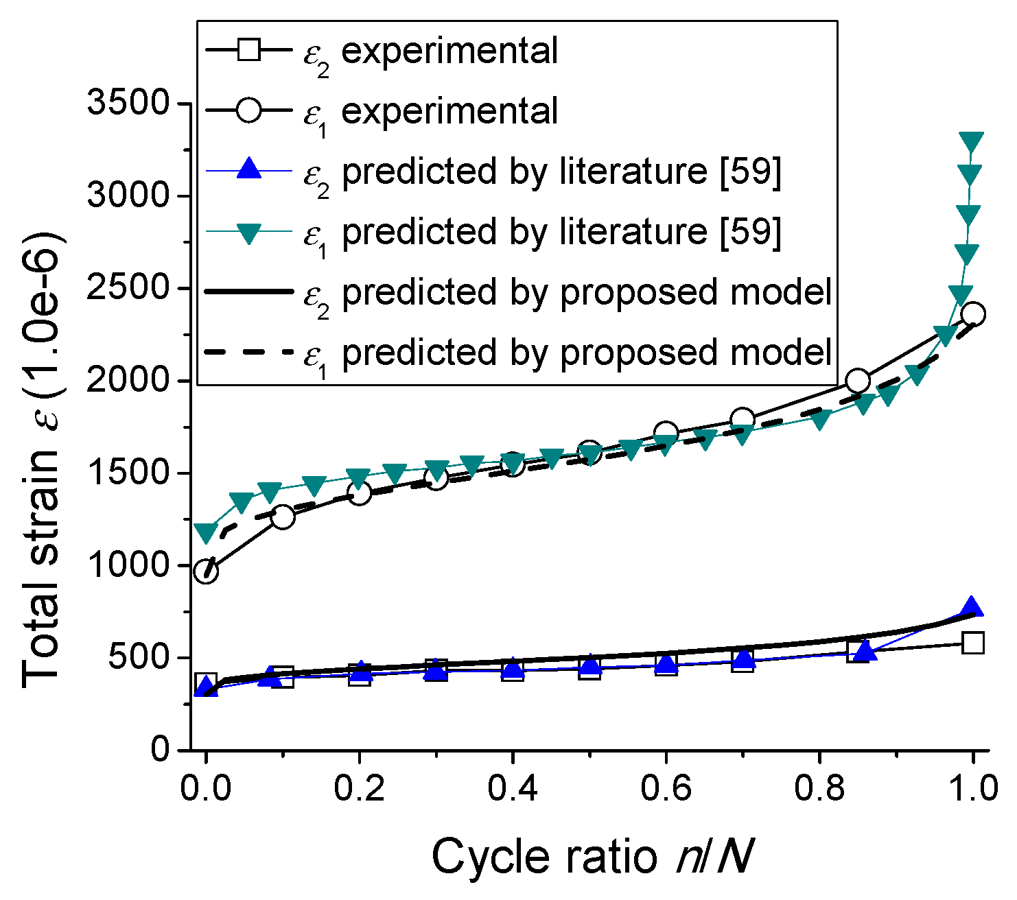
In order to model the behaviors of concrete under fatigue compression with various stress levels of constant amplitudes, a typical result [4] is used for analysis in this section. The parameters are calibrated as follows, E0 = 21.8 GPa, fcu− = 26.0 MPa, A1− = 0, A2− = 1, ε0− = 2306.5 με, p− = 2.464, A3− = 0.713, A4− = 1.160, A5− = 5.439. The cyclic creep and the fatigue strain [4] (defined as the fatigue strain = the total strain εn—the initial strain (i.e., the total strain in the first cycle ε1)) are predicted and compared with experimental results in Figure 9.
Figure 9 illustrates that the predictions agree with the experimental results. In detail, initially, both the total fatigue strains and the fatigue strains in predictions agree with the experimental results. Additionally, the proposed model is able to reproduce the three stages evolution of total fatigue strains and fatigue strains during fatigue life. It is noted that the tail results in predictions are slightly higher than the experimental results, since the strain due to static stress-strain response in concrete is developing faster than the total fatigue strains in experiments [4], which leads to the higher strains predictions (Figure 9) by using Equations (40) and (60) based on fatigue failure surface concept [4]. Therefore, the proposed model is able to characterize the behaviors of concrete under fatigue compression with various stress levels with constant amplitudes.
4.4. Behaviors of Concrete under Biaxial Fatigue Compression
In order to model the behaviors of concrete under biaxial fatigue compression with constant amplitude, a typical result [58] (Figure 10) is applied for analysis in this section. The parameters are calibrated as follows, E0 = 26.3 GPa, fcu− = 20.47 MPa, A1− = 0, A2− = 1, ε0− = 1568.1 με, p− = 2.218, A3− = 0.713, A4− = 1.160, A5− = 5.439 and α1 = 1.254. Figure 10 illustrates that the predicted results of the proposed model agree well with the experimental results. Therefore, it can be concluded that the proposed model is applicable in the analysis of concrete under biaxial fatigue loading.
4.5. Post-Fatigue Constitutive Behaviors of Concrete under Monotonic Loading
To verify the effectiveness of the proposed model in predicting the post-fatigue stress–strain response of concrete, the literature [59] is applied to calibrate the parameters, as follows, E0− = 36.0 GPa, fcu− = 41.4 MPa, A1− = 0, A2− = 1, ε0− = 2153.8 με, p− = 3.186, A3− = 0.713, A4− = 1.160, A5− = 5.439. The predicted post-fatigue stress-strain responses are obtained in Figure 11a. Figure 11a illustrates that the post-fatigue stress–strain responses predicted by the model varies in a typical three stages way depending on the increasing of cycle ratio. In detail, the development of the initial strains (i.e., the residual strains) of the responses grows in a three stages way, and the variation of the initial (post-fatigue) stiffness and the residual strength experience in a similar way. Therefore, the proposed model is able to reproduce the post-fatigue constitutive behaviors.
4.6. Comparison among Proposed Model and Other Models
The proposed model is compared with the typical damage evolution models [60,61]. The parameters are calibrated by using the experimental results in the literature [61], such that, E0− = 54.5 GPa, A3− = 0.6, A4− = 1.01, A5− = 9, B1 = 2.29, B2 = −1.23, and B3 = 0. Thus, the predictions are obtained in Figure 11b–d. Figure 10 and Figure 11b illustrate that the predictions of the proposed model are more accurate than those of other damage evolution models [60,61]. In addition, the proposed model is able to reproduce the other behavior variations under fatigue loading (e.g., the development of cyclic creep (Figure 10 and Figure 11c), stiffness degradation (Figure 11d) and post-fatigue constitutive behavior (Figure 11a), which are not well considered in the other models [60,61].
Furthermore, the proposed models are capable of predicting the variations of cyclic creep, stiffness degradation, residual strength, and the stress–strain relationship under both fatigue loading and post-fatigue loading. However, few damage models [6,41,42,43,44,45,46,47,48,49] took all the characteristics above into account for relevant characterizing.
Additionally, the proposed model obtains a clear physical consideration based on the micro mechanical description of damage behaviors in concrete under multi-axial loading, and proposed a behavior characterizing method based on both the above-mentioned description and a thermodynamics-based CDM method. However, in the classical damage models [44,45], the yield concept cannot coexist with the loading/unloading irreversible strain concept [62] introduced in their framework. In detail, in the yield concept [44,45], there is only one yield surface for determining the plastic strains in the material. However, in the loading/unloading irreversible strain concept [62], each loading/unloading process (i.e., a loading cycle) obtains a corresponding irreversible strain surface for the development of irreversible strains.
5. Conclusions
In this work, a damage model with the concept of mode-II microcracks using thermodynamic interpretation of damage behaviors for concrete under fatigue loading was developed.
In detail, by applying the micromechanics method, a micro-cell-based damage model was introduced to understand the damage behavior. The mode-II microcracks were further introduced as a contributing part of irreversible/residual strains.
Additionally, by introducing the physical interpretation of the damage variable based on the thermodynamic method, a novel fatigue damage variable (irreversible deformation fatigue damage variable) was proposed to describe the irreversible strains. With this methodology, a continuum damage mechanics model considered both the elastic and irreversible deformation fatigue damages was developed.
It is found that the predictions of this model highly agreed with experimental results. This model is able to characterize the variations of cyclic creep, stiffness degradation, residual strength, and the post-fatigue stress-strain relationship of concrete. The model can also be used to analyze the behaviors of concrete under complex fatigue loads such as a multi-axial case.
Author Contributions
Conceptualization, Z.S., Z.Y., X.L. (Xiao Li), X.L. (Xiaoyong Lv) and Z.L.; methodology, Z.S., Z.Y., X.L. (Xiao Li), X.L. (Xiaoyong Lv) and Z.L.; software, Z.S., Z.Y., X.L. (Xiao Li), X.L. (Xiaoyong Lv) and Z.L.; validation, Z.S., Z.Y., X.L. (Xiao Li), X.L. (Xiaoyong Lv) and Z.L.; formal analysis, Z.S., Z.Y., X.L. (Xiao Li), X.L. (Xiaoyong Lv) and Z.L.; investigation, Z.S., Z.Y., X.L. (Xiao Li), X.L. (Xiaoyong Lv) and Z.L.; resources, Z.S., Z.Y., X.L. (Xiao Li), X.L. (Xiaoyong Lv) and Z.L.; data curation, Z.S., Z.Y., X.L. (Xiao Li), X.L. (Xiaoyong Lv) and Z.L.; writing—original draft preparation, Z.S., Z.Y., X.L. (Xiao Li), X.L. (Xiaoyong Lv) and Z.L.; writing—review and editing, Z.S., Z.Y., X.L. (Xiao Li), X.L. (Xiaoyong Lv) and Z.L.; visualization, Z.S., Z.Y., X.L. (Xiao Li), X.L. (Xiaoyong Lv) and Z.L.; supervision, Z.S. and Z.Y.; project administration, Z.S. and Z.Y.; funding acquisition, Z.S. and Z.Y.
Funding
This research was supported by the National Key R&D Program of China, grant number 2018YFD1100401; the National Natural Science Foundation of China, grant numbers 51808558, 51820105014, U1434204, 51378506, 51478478; the Natural Science Foundation of Hunan Province, China, grant number 2019JJ50800; the China Energy Investment Corporation, grant number SHGF-18-50.
Conflicts of Interest
The authors declare no conflict of interest.
Appendix A. Damage Variable Definition Based on Thermodynamics
(1) Perfect elastic materials
The Helmholtz free energy of a perfect elastic material per unit mass is obtained as follows (see Figure A1a):
And the energy dissipation χ is introduced in this work (see Figure A1), that is,
where χ denotes that energy dissipation exists as a typical property of the elastic behaviors, it accompanies the initial strain energy ψ0e, and both are equal to each other like the twins, see Figure A1.
There is no damage appearing in the material, thus, it is not necessary to define a damage variable. And the stress–strain relation is described as follows:
(2) Elastic deformation damage materials
The Helmholtz free energy of an elastic deformation damage material is obtained as follows (see Figure A1b):
where
The elastic deformation damage variable in the elastic strain space is defined in this work by two methods considering two different energy dissipation aspects, respectively, as follows:
where εE denotes the elastic strains, εE = ε0 + εde.
The nonlinear stress–strain relation is described as follows:
The damage variable DE is able to be used to describe the stiffness degradation, that is (Figure A1b),
Figure A1.
Sketch of the energy dissipation for various materials under uniaxial loading.
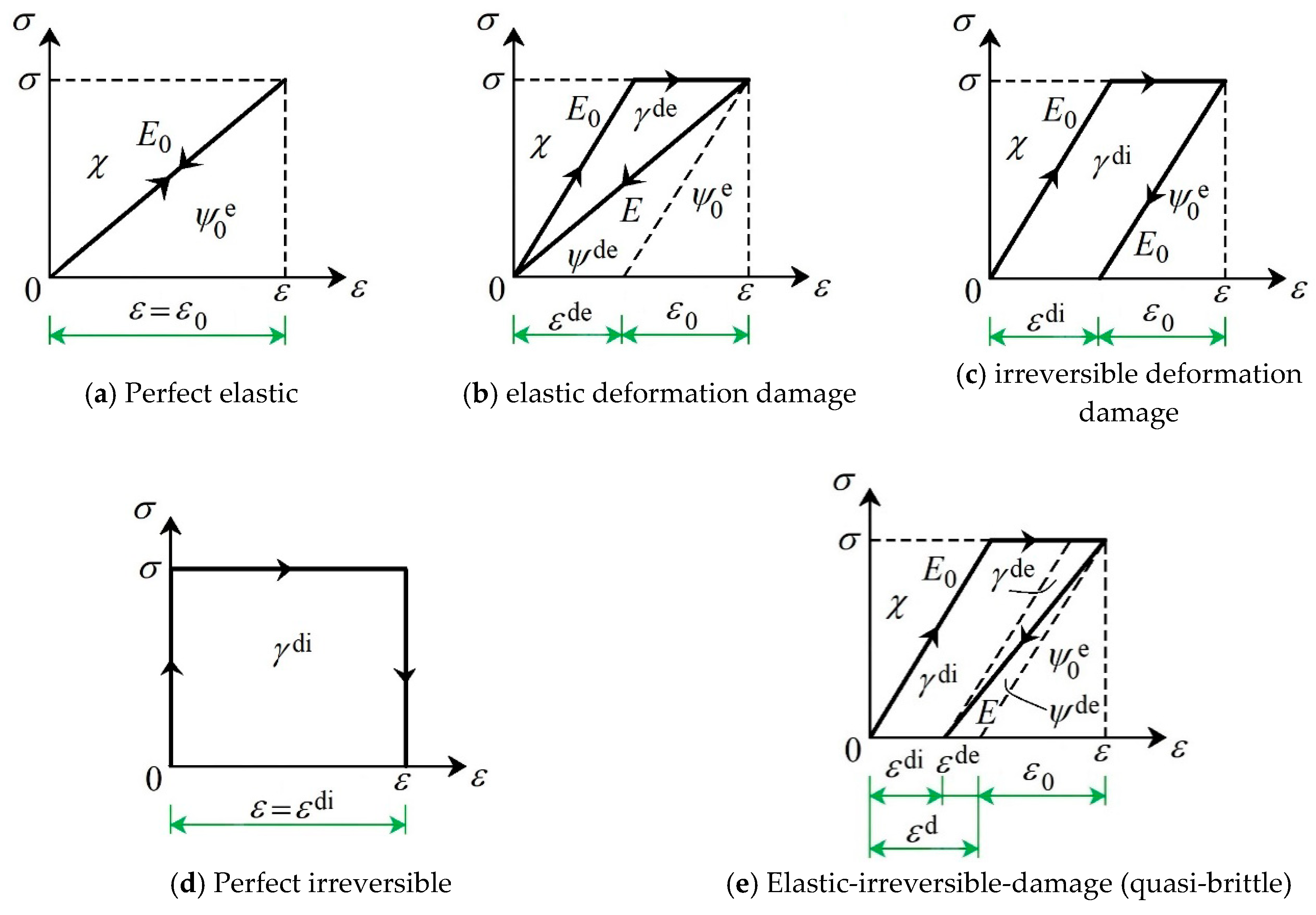
(3) Irreversible deformation damage materials
The Helmholtz free energy of an irreversible deformation damage material is obtained as follows (see Figure A1c):
The irreversible deformation damage variable is defined in this work by the method considering energy dissipation, as follows:
where ε = ε0 + εdi.
The nonlinear stress–strain relation is described as follows:
The damage variable Di is able to be used to describe the irreversible strain development, that is (see Figure A1c),
Additionally, when the initial stiffness approaches an infinite value ∞, the material exhibits a prefect brittle-plastic behavior (see Figure A1d). Thus, the Helmholtz free energy is derived as follows,
due to the energy dissipation χ = ψ0e = 0. The irreversible deformation damage variable is obtained, as follows:
And the irreversible strain is derived, as follows:
Furthermore, the nonlinear stress-strain relation is described as follows:
(4) Quasi-brittle materials (Elastic-irreversible deformation damage materials)
The Helmholtz free energy of a quasi-brittle material is obtained as follows (see Figure A1e):
where
The elastic deformation damage variable in the elastic strain space is defined in this work by two methods considering two different energy dissipation aspects, respectively, as follows:
The elastic deformation damage variable in the total strain space is also defined in this work by the method considering energy dissipation, as follows:
where the total strain ε = ε0 + εde + εdi, and the elastic strain εE = ε0 + εde.
The irreversible deformation damage variable is defined in this work by the method considering energy dissipation, as follows:
The nonlinear stress–strain relation is described as follows:
The damage variable DE (or De) and Di is able to be employed to characterize the stiffness degradation and irreversible strain development, respectively, as follows (see Figure A1e),
Note that the energy dissipation χ presents a typical property of materials’ elastic behaviors. Figure A1 and Equations (A2), (A6), (A12) and (A22) show that the energy dissipation χ is equal to the initial strain energy ψ0e, i.e., χ = ψ0e, and in a limit case without elastic behaviors in Figure A1d, χ = ψ0e = 0. Additionally, the damage variable definition method considering the energy dissipation χ in Equations (A8) and (A24) is as effective as that in Equations (A7) and (A23), respectively. Therefore, it is reasonable to apply the damage variable definition method considering the energy dissipation χ in this work.
References
- Susmel, L. A unifying methodology to design un-notched plain and short-fibre/particle reinforced concretes against fatigue. Int. J. Fatigue 2014, 61, 226–243. [Google Scholar] [CrossRef]
- Chen, Y.; Ni, J.; Zheng, P.; Azzam, R.; Zhou, Y.; Shao, W. Experimental research on the behaviour of high frequency fatigue in concrete. Eng. Fail. Anal. 2011, 18, 1848–1857. [Google Scholar] [CrossRef]
- Guo, L.P.; Carpinteri, A.; Spagnoli, A.; Wei, S. Effects of mechanical properties of concrete constituents including active mineral admixtures on fatigue behaviours of high performance concrete. Fatigue Fract. Eng. Mater. Struct. 2010, 33, 66–75. [Google Scholar]
- Kim, J.K.; Kim, Y.Y. Experimental study of the fatigue behavior of high strength concrete. Cem. Concr. Res. 1996, 26, 1513–1523. [Google Scholar] [CrossRef]
- Nor, N.M.; Ibrahim, A.; Bunnori, N.M.; Saman, H.M.; Saliah, S.N.M.; Shahidan, S. Diagnostic of fatigue damage severity on reinforced concrete beam using acoustic emission technique. Eng. Fail. Anal. 2014, 41, 1–9. [Google Scholar] [CrossRef]
- Bazant, Z.P.; Hubler, M.H. Theory of cyclic creep of concrete based on Paris law for fatigue growth of subcritical microcracks. J. Mech. Phys. Solids 2014, 63, 187–200. [Google Scholar] [CrossRef]
- Saucedo, L.; Yu, R.C.; Medeiros, A.; Zhang, X.X.; Ruiz, G. A probabilistic fatigue model based on the initial distribution to consider frequency effect in plain and fibre reinforced concrete. Int. J. Fatigue 2013, 48, 308–318. [Google Scholar] [CrossRef]
- Bazant, Z.P.; Panula, L. Practical prediction of time-dependent deformations of concrete. Part VI: Cyclic creep, nonlinearity and statistical scatter. Mater. Struct. 1979, 12, 175–183. [Google Scholar]
- Breitenbucher, R.; Ibuk, H. Experimentally based investigations on the degradation process of concrete under cyclic load. Mater. Struct. 2006, 39, 717–724. [Google Scholar] [CrossRef]
- Neville, A.M.; Hirst, G.A. Mechanism of cyclic creep of concrete. In Douglas McHenry International Symposium on Concrete and Concrete Structures; ACISP-55; Special Publication: London, UK, 1978; pp. 83–101. [Google Scholar]
- Garrett, G.G.; Jennings, H.M.; Tait, R.B. The fatigue hardening behavior of cement-based materials. J. Mater. Sci. 1979, 14, 296–306. [Google Scholar] [CrossRef]
- Le, J.L.; Bazant, Z.P. Unified nano-mechanics based probabilistic theory of quasibrittle and brittle structures: II. Fatigue crack growth, lifetime and scaling. J. Mech. Phys. Solids 2011, 59, 1322–1337. [Google Scholar] [CrossRef]
- Slate, F.O.; Olsefski, S. X-Rays for Study of Internal Structure and Microcracking of Concrete. J. Am. Concr. Inst. 1963, 60, 575–588. [Google Scholar]
- Abu Al-Rub, R.K.; Voyiadjis, G.Z. On the coupling of anisotropic damage and plasticity models for ductile Materials. Int. J. Solids Struct. 2003, 40, 2611–2643. [Google Scholar] [CrossRef]
- Paskin, A.; Massoumzadeh, B.; Shukla, K.; Sieradzki, K.; Dienes, G.J. Effect of atomic crack tip geometry on local stresses. Acta Met. 1985, 33, 1987–1996. [Google Scholar] [CrossRef]
- Dienes, G.J.; Paskin, A. Molecular dynamic simulations of crack propagation. J. Phys. Chem. Solids 1987, 48, 1015–1033. [Google Scholar] [CrossRef]
- Gumbsch, P. An atomistic study of brittle fracture: Toward explicit failure criteria from atomistic modeling. J. Mater. Res. 1995, 10, 2897–2907. [Google Scholar] [CrossRef]
- Gumbsch, P.; Beltz, G.E. On the continuum versus atomistic descriptions of dislocation nucleation and cleavage in nickel. Model. Simul. Mater. Sci. Eng. 1995, 3, 597–613. [Google Scholar] [CrossRef]
- Zhou, Z.L.; Gu, J.L.; Chen, N.P.; Li, D.C.; Liu, H.Q. Comparison of finite element calculation and experimental study of elastic-plastic deformation at crack tip. Acta Mech. Sin. 1995, 27, 51–57. [Google Scholar]
- Fischer, L.L.; Beltz, G.E. The effect of crack blunting on the competition between dislocation nucleation and Cleavage. J. Mech. Phys. Solids 2001, 49, 635–654. [Google Scholar] [CrossRef]
- Hajlaoui, K.; Yavari, A.R.; Doisneau, B.; LeMoulec, A.; Vaughan, G.; Greer, A.L.; Inoue, A.; Zhang, W.; Kvick, Å. Shear delocalization and crack blunting of a metallic glass containing nanoparticles: In situ deformation in TEM analysis. Scr. Mater. 2006, 54, 1829–1834. [Google Scholar] [CrossRef]
- Yu, Z.; Shan, Z.; Ouyang, Z.; Guo, F. A simple damage model for concrete considering irreversible mode-II microcracks. Fatigue Fract. Eng. Mater. Struct. 2016, 39, 1419–1432. [Google Scholar] [CrossRef]
- Yu, Z.W.; Tan, S.; Shan, Z.; Tian, X.Q. X-ray computed tomography quantification of damage in concrete under compression considering irreversible mode-II microcracks. Fatigue Fract. Eng. Mater. Struct. 2017, 40, 1960–1972. [Google Scholar] [CrossRef]
- Suresh, S.; Tschegg, E.K.; Brockenbrough, J.R. Fatigue Crack growth in cementitious composites under cyclic compressive loads. Cem. Concr. Res. 1989, 19, 827–833. [Google Scholar] [CrossRef]
- Eliáš, J.; Le, J.L. Modeling of mode-I fatigue crack growth in quasi brittle structures under cyclic compression. Eng. Fract. Mech. 2012, 96, 26–36. [Google Scholar]
- Bazant, Z.P.; Xiang, Y. Size effect in compression fracture: Splitting crack band propagation. J. Eng. Mech. 1997, 123, 207–213. [Google Scholar] [CrossRef]
- Fairhurst, C.; Comet, F. Rock fracture and fragmentation. In Rock Mechanics: From Research to Application. Proceedings of the U.S. Symposium on Rock Mechanics; Einstein, H.H., Ed.; MIT Press: Cambridge, MA, USA, 1981; pp. 21–46. [Google Scholar]
- Sammis, C.G.; Ashby, M.F. The failure of brittle porous solids under compressive stress state. Acta Metall. 1986, 34, 511–526. [Google Scholar] [CrossRef]
- Horii, H.; Nemat-Nasser, S. Compression induced nonplanar crack extension with application to splitting, exfoliation and rock burst. J. Geophys. Res. 1982, 87, 6805–6822. [Google Scholar]
- Kachanov, M. A micro crack model of rock in elasticity—Part I. Frictional sliding on micro cracks. Mech. Mater. 1982, 1, 19–27. [Google Scholar] [CrossRef]
- Nemat-Nasser, S.; Obata, M. A microcrack model of dilatancy in brittle materials. J. Appl. Mech. 1988, 55, 24–35. [Google Scholar] [CrossRef]
- Budiansky, B.; O’Connell, R.J. Elastic moduli of a cracked solid. Int. J. Solids Strcut. 1976, 12, 81–97. [Google Scholar] [CrossRef]
- Ning, J.; Ren, H.; Fang, M. Reseasrch on the process of micro-crack damage evolution and coalescence in brittle materials. Eng. Fail. Anal. 2014, 41, 65–72. [Google Scholar]
- Hu, G.; Liu, J.; Graham-Brady, L.; Ramesh, K.T. A 3D mechanistic model for brittle materials containing evolving flaw distributions under dynamic multiaxial loading. J. Mech. Phys. Solids 2015, 78, 269–297. [Google Scholar] [CrossRef]
- Burr, A.; Hild, F.; Leckie, F.A. Micro-mechanics and continuum damage mechanics. Arch. Appl. Mech. 1995, 65, 437–456. [Google Scholar] [CrossRef]
- Mazars, J.; Pijaudier-Cabot, G. Continuum damage theory—Application to concrete. J. Eng. Mech. 1989, 115, 345–365. [Google Scholar] [CrossRef]
- Halm, D.; Dragon, A. An anisotropic model of damage and frictional sliding for brittle materials. Eur. J. Mech. A Solids 1998, 17, 439–460. [Google Scholar] [CrossRef]
- Dragon, A.; Halm, D.; Desoyer, T. Anisotropic damage in quasi-brittle solids: Modelling, computational issues and applications. Comput. Methods Appl. Mech. Eng. 2000, 183, 331–352. [Google Scholar] [CrossRef]
- Le, J.L.; Bazant, Z.P.; Bazant, M.Z. Unified nano-mechanics based probabilistic theory of quasibrittle and brittle structures: I. Strength, static crack growth, lifetime and scaling. J. Mech. Phys. Solids 2011, 59, 1291–1321. [Google Scholar] [CrossRef]
- Feng, X.Q.; Gross, D. Three-dimensional micromechanical model for quasi-brittle solids with residual strains under tension. Int. J. Damage Mech. 2000, 9, 79–110. [Google Scholar] [CrossRef]
- Xiao, J.Z.; Li, H.; Yang, Z.J. Fatigue behavior of recycled aggregate concrete under compression and bending cyclic loadings. Constr. Build. Mater. 2013, 38, 681–688. [Google Scholar] [CrossRef]
- Pandolfi, A.; Taliercio, A. Bounding surface models applied to fatigue of plain concrete. J. Eng. Mech. 1998, 5, 556–564. [Google Scholar] [CrossRef]
- Papa, E.; Taliercio, A. Anisotropic damage model for the multiaxial static and fatigue behavior for plain concrete. Eng. Fract. Mech. 1996, 55, 163–179. [Google Scholar] [CrossRef]
- Alliche, A. Damage model for fatigue loading of concrete. Int. J. Fatigue 2004, 26, 915–921. [Google Scholar] [CrossRef]
- Mai, S.H.; Le-Corre, F.; Forêt, G.; Nedjar, B. A continuum damage modeling of quasi-static fatigue strength of plain concrete. Int. J. Fatigue 2012, 37, 79–85. [Google Scholar] [CrossRef] [Green Version]
- Lemaitre, J.; Lippmann, H. A Course on Damage Mechanics; Springer: Berlin, Germany, 1996. [Google Scholar]
- Richard, B.; Ragueneau, F.; Cremona, C.; Adelaide, L. Isotropic continuum damage mechanics for concrete under cyclic loading: Stiffness recovery, inelastic strains and frictional sliding. Eng. Fract. Mech. 2010, 77, 1203–1223. [Google Scholar] [CrossRef]
- Lu, P.Y.; Li, Q.B.; Song, Y.P. Damage constitutive of concrete under uniaxial alternate tension- compression fatigue loading based on double bounding surfaces. Int. J. Solids Struct. 2004, 41, 3151–3166. [Google Scholar] [CrossRef]
- Najar, J. Brittle residual strain and continuum damage at variable uniaxial loading. Int. J. Damage Mech. 1994, 3, 260–276. [Google Scholar] [CrossRef]
- Shan, Z.; Yu, Z.W. A fiber bundle-plastic chain model for quasi-brittle materials under uniaxial loading. J. Stat. Mech. Theory Exp. 2015, 2015, P11010. [Google Scholar] [CrossRef]
- Yazdani, S.; Schreyer, H.L. Combined plasticity and damage mechanics model for plain concrete. J. Eng. Mech. 1990, 116, 1435–1450. [Google Scholar] [CrossRef]
- Voyiadjis, G.Z.; Park, T. The kinematics of damage for finite-strain elasto-plastic solids. Int. J. Eng. Sci. 1999, 37, 803–830. [Google Scholar] [CrossRef]
- Li, J.; Wu, J.Y.; Chen, J.B. Stochastic Damage Mechanics of Concrete Structure; Science Press: Beijing, China, 2017. (In Chinese) [Google Scholar]
- Yu, Z.W.; Song, L.; Xie, Y.; Shan, Z. Experimental study on performance of CRTS III slab ballastless track system under service condition. In Third Report: Numerical Simulation on Fatigue Performance of CRTS III Slab Ballastless Track Structure Under High Speed Train Load; China State Railway Group Co., Ltd.: Beijing, China, 2015. (In Chinese) [Google Scholar]
- Sima, J.F.; Roca, P.; Molins, C. Cyclic constitutive model for concrete. Eng. Struct. 2008, 30, 695–706. [Google Scholar] [CrossRef] [Green Version]
- Research Group on Concrete Fatigue Behaviors. Reliability Evaluation Method of Concrete Bending Members under Fatigue Loading; China Architecture & Building Press: Beijing, China, 1994. (In Chinese) [Google Scholar]
- Thomas, C.; Setien, J.; Polanco, J.A.; Lompillo, I.; Cimentada, A. Fatigue limit of recycled aggregate concrete. Constr. Build. Mater. 2014, 52, 146–154. [Google Scholar] [CrossRef] [Green Version]
- Lu, P.; Song, Y.; Li, Q. Behavior of concrete under compressive fatigue loading with constant lateral stress. Eng. Mech. 2004, 21, 173–177. [Google Scholar]
- The National Standard of the People’s Republic of China: Code for Design of Concrete Structures (GB50011-2010); China Building Industry Press: Beijing, China, 2010. (In Chinese)
- Liang, J.S.; Ren, X.D.; Li, J. A competitive mechanism driven damage-plasticity model for fatigue behavior of concrete. Int. J. Damage Mech. 2016, 25, 377–399. [Google Scholar] [CrossRef]
- Xiao, J. Theoretical and Experimental Investigation on Fatigue Properties of Rock under Cyclic Loading. Master’s Thesis, Central South University, Changsha, China, 2009. (In Chinese). [Google Scholar]
- Marigo, J. Modelling of brittle and fatigue damage for elastic material by growth of microvoids. Eng. Fract. Mech. 1985, 21, 861–874. [Google Scholar] [CrossRef]
Figure 1.
Sketch of stress flow curve around the random selected micro-cell of the representative volume element (RVE) in the specimen under multi-axial tension, and the related coordinates and dimension, where σ1 denotes the maximum principal tensile stress.
Figure 1.
Sketch of stress flow curve around the random selected micro-cell of the representative volume element (RVE) in the specimen under multi-axial tension, and the related coordinates and dimension, where σ1 denotes the maximum principal tensile stress.

Figure 2.
Sketch of microcracks under multi-axial tension, leading to both the stiffness degrading and the irreversible strain developing, where σ1 denotes the maximum principal tensile stress.
Figure 2.
Sketch of microcracks under multi-axial tension, leading to both the stiffness degrading and the irreversible strain developing, where σ1 denotes the maximum principal tensile stress.

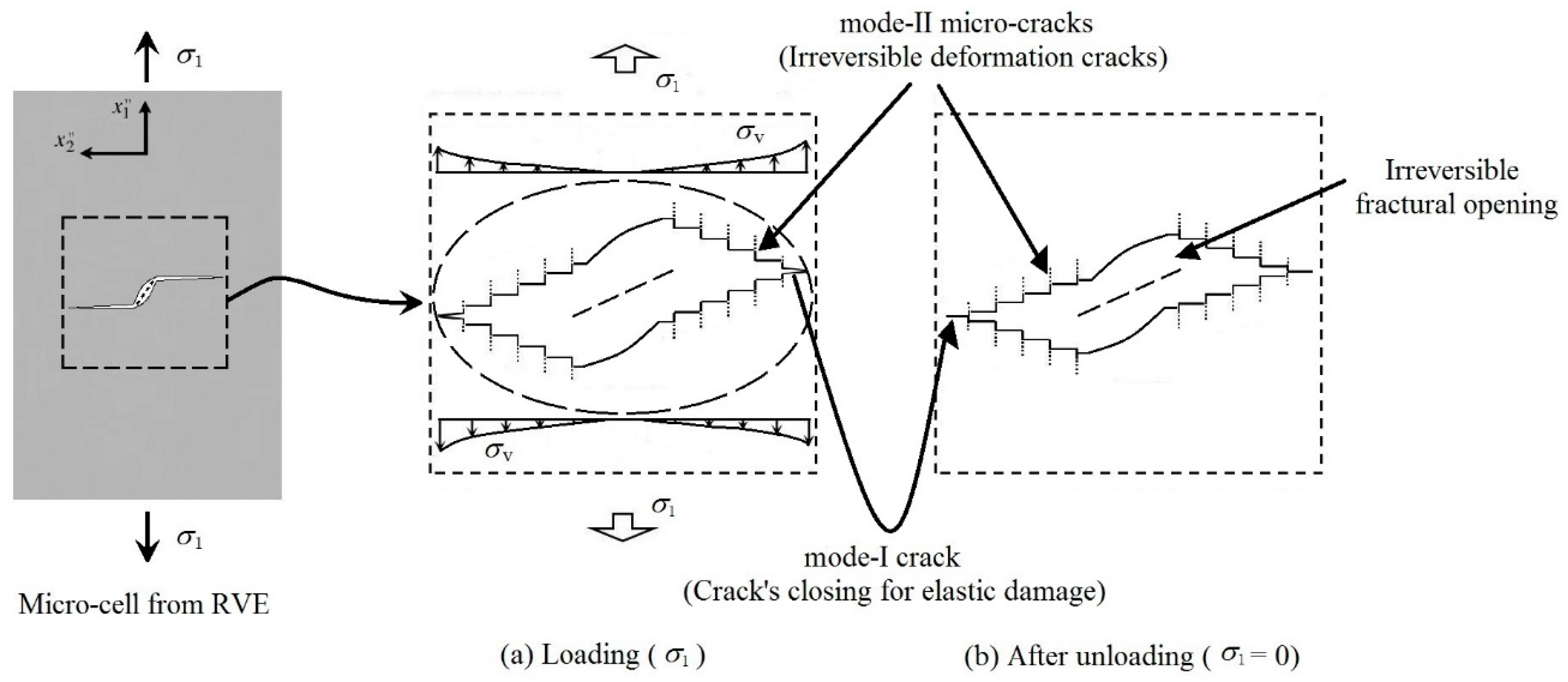
Figure 3.
Macro behaviors and micro mechanism of a concrete cube under bi-axial tension from various loading statuses. This figure was developed based on [22] (Reproduced with permission from [John Wiley & Sons Ltd], 2016), however, the random distribution of initial defects was considered in this work.
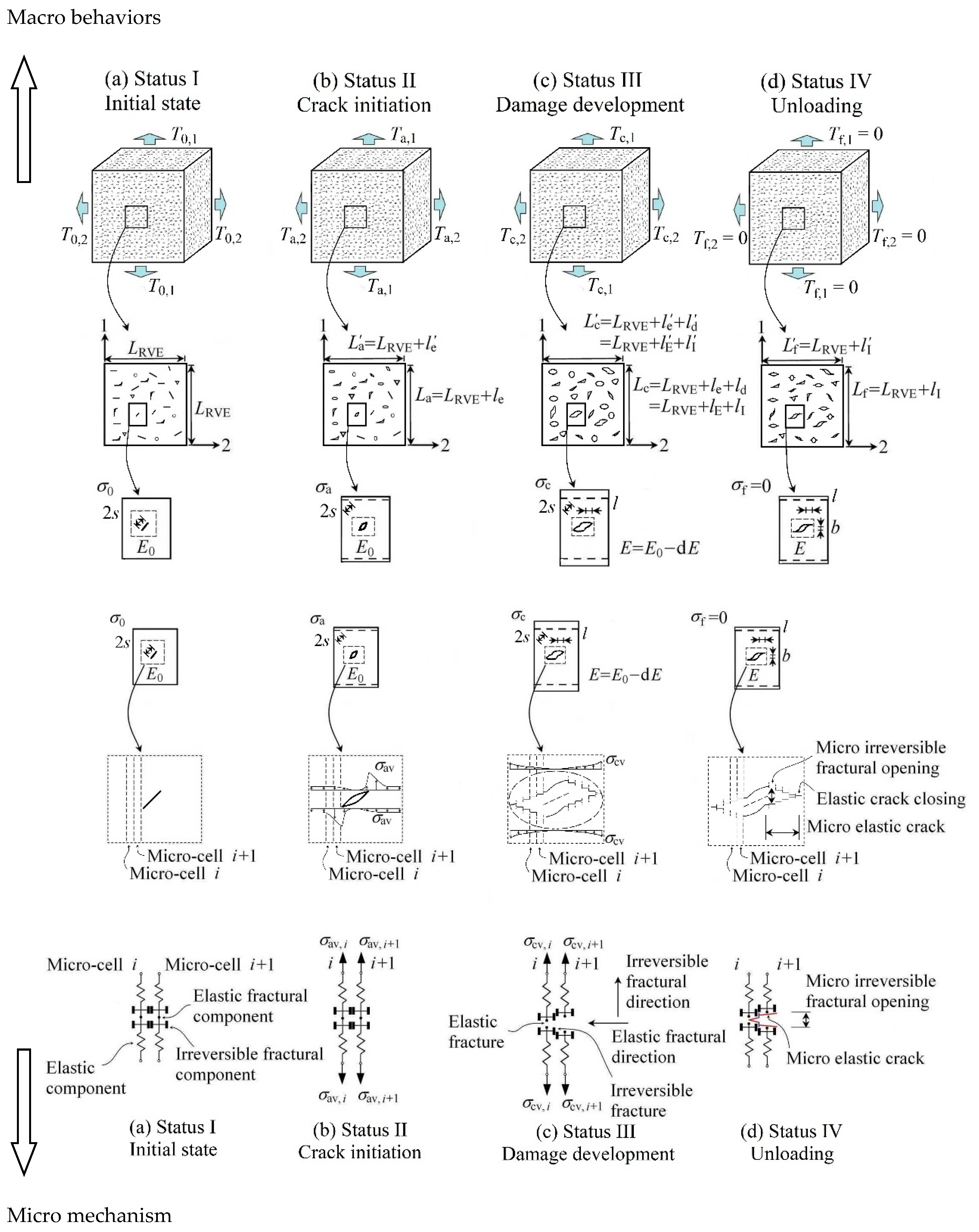
Figure 4.
Sketch of tensile irreversible deformations due to both mode-II microcracks and irreversible frictional sliding, where σ1 denotes the maximum principal tensile stress in multi-axial tension. This figure was developed based on [22] (Reproduced with permission from [John Wiley & Sons Ltd], 2016), however, the random distribution of initial defects was considered in this work.

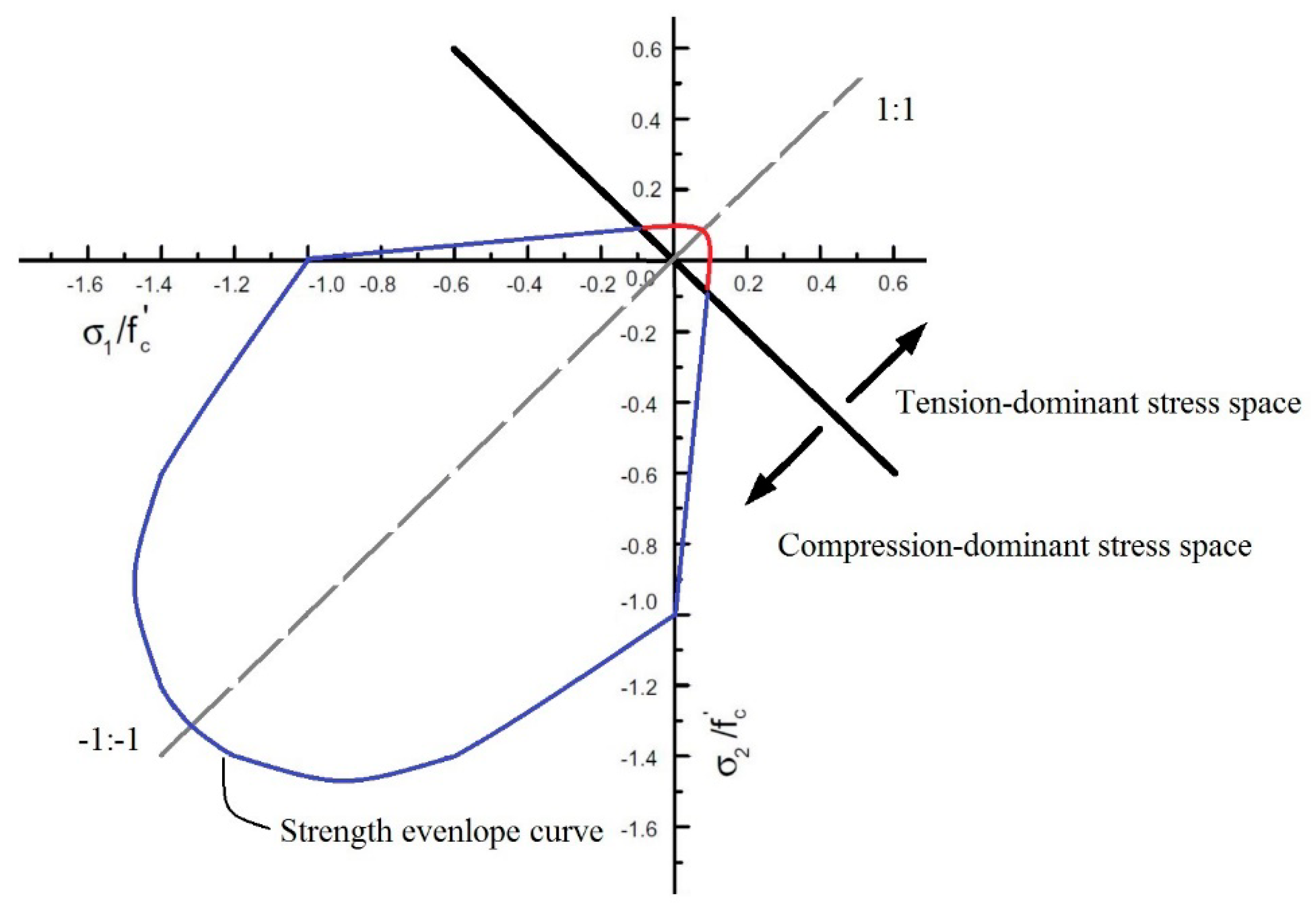
Figure 5.
Sketch of the tension- and compression-dominant stress space in two-dimensional.

Figure 6.
Thermodynamics interpretation of micro-scale damage behaviors. Specifically, the elastic deformation damage (mode-I cracks) produces the stiffness reduction Ed, and the irreversible deformation damage (both mode-II microcracks and irreversible friction sliding) causes the development of irreversible strains εI.
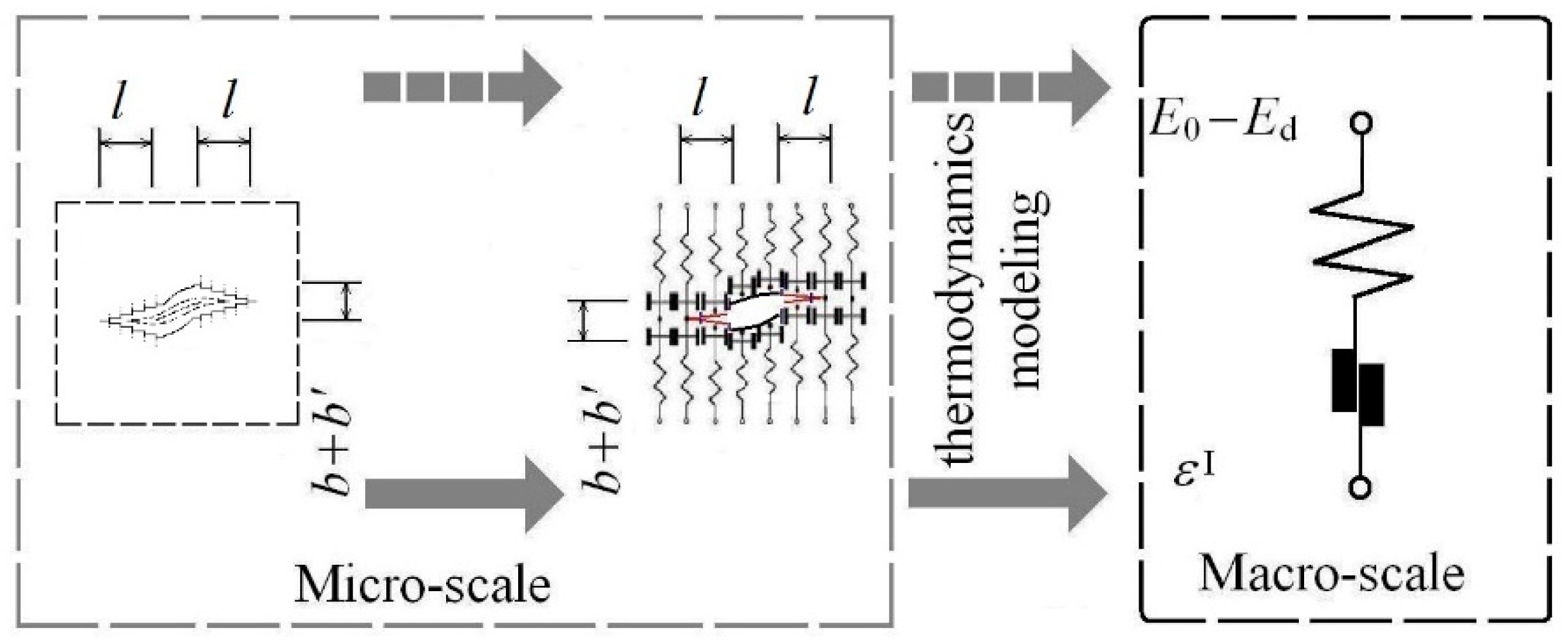
Figure 7.
Sketch of the mechanical parameter definition for concrete under fatigue loading. (a) Energy dissipation; (b) Energy dissipation; (c) Energy dissipation (σmin = 0); (d) Energy dissipation (σmin ≠ 0);
Figure 7.
Sketch of the mechanical parameter definition for concrete under fatigue loading. (a) Energy dissipation; (b) Energy dissipation; (c) Energy dissipation (σmin = 0); (d) Energy dissipation (σmin ≠ 0);

Figure 8.
Calibration of parameters in the model, and comparison between experimental [57] (The graphs are completely redrawn by authors).and predicted results.
Figure 8.
Calibration of parameters in the model, and comparison between experimental [57] (The graphs are completely redrawn by authors).and predicted results.

Figure 9.
Comparison of total fatigue strains (a) and fatigue strains (b) between predicted and experimental [4] (The graphs are completely redrawn by authors). results, where the fatigue strain = the total strain εn—the initial strain (i.e., the total strain in the first cycle ε1).
Figure 9.
Comparison of total fatigue strains (a) and fatigue strains (b) between predicted and experimental [4] (The graphs are completely redrawn by authors). results, where the fatigue strain = the total strain εn—the initial strain (i.e., the total strain in the first cycle ε1).

Figure 10.
Comparison of cyclic creep under biaxial fatigue compression among predicted and experimental results [58] (The graphs are completely redrawn by authors).
Figure 10.
Comparison of cyclic creep under biaxial fatigue compression among predicted and experimental results [58] (The graphs are completely redrawn by authors).

Figure 11.
Post-fatigue stress–strain response predicted by the proposed model (n/N = 0.02~0.98, S = 0.66), and comparison of Di, cyclic creep and stiffness degradation among predicted and experimental results [61] (The graphs are redrawn by authors).
Figure 11.
Post-fatigue stress–strain response predicted by the proposed model (n/N = 0.02~0.98, S = 0.66), and comparison of Di, cyclic creep and stiffness degradation among predicted and experimental results [61] (The graphs are redrawn by authors).

© 2019 by the authors. Licensee MDPI, Basel, Switzerland. This article is an open access article distributed under the terms and conditions of the Creative Commons Attribution (CC BY) license (http://creativecommons.org/licenses/by/4.0/).
Share and Cite
MDPI and ACS Style
Shan, Z.; Yu, Z.; Li, X.; Lv, X.; Liao, Z. A Damage Model for Concrete under Fatigue Loading. Appl. Sci. 2019, 9, 2768. https://doi.org/10.3390/app9132768
AMA Style
Shan Z, Yu Z, Li X, Lv X, Liao Z. A Damage Model for Concrete under Fatigue Loading. Applied Sciences. 2019; 9(13):2768. https://doi.org/10.3390/app9132768
Chicago/Turabian StyleShan, Zhi, Zhiwu Yu, Xiao Li, Xiaoyong Lv, and Zhenyu Liao. 2019. "A Damage Model for Concrete under Fatigue Loading" Applied Sciences 9, no. 13: 2768. https://doi.org/10.3390/app9132768
Note that from the first issue of 2016, this journal uses article numbers instead of page numbers. See further details here.