The Impact of Space-Based AIS Antenna Orientation on In-Orbit AIS Detection Performance


1
Satellite Technology Center, National Institute of Aeronautics and Space (LAPAN), Bogor 16310, Indonesia
2
Biak Satellite Control Center, Space and Atmospheric Observation, and Remote Sensing Office, National Institute of Aeronautics and Space (LAPAN), Biak 98117, Indonesia
3
Institut für Luft- und Raumfahrt (ILR), Technische Universitat Berlin, 10623 Berlin, Germany
*
Author to whom correspondence should be addressed.
Appl. Sci. 2019, 9(16), 3319; https://doi.org/10.3390/app9163319
Submission received: 4 June 2019
/
Revised: 6 August 2019
/
Accepted: 9 August 2019
/
Published: 13 August 2019
(This article belongs to the Section Earth Sciences)
Abstract
:In this paper, a study on the impact of changing the space-based Automatic Identification System (AIS) monopole antenna orientation on its message reception performance in orbit has been conducted. The study has been carried out by maneuvering the attitude of LAPAN-A2, an equatorial orbiting microsatellite with AIS antenna fixedly mounted on the satellite’s body, into the desired orientation. Based on the analysis of the datasets collected during the maneuver, the orientation of AIS monopole antenna 45° toward its flight direction increases the overall detection performance of the AIS message, including class A ship to 208.80% and also class B ships to 175.93%. This orientation also increases the detection of AIS messages in ocean areas having low detection probability due to AIS signal collision. The result of this research could become a reference in order to specify AIS antenna position and orientation in a small satellite carrying a space-based AIS system for maritime surveillance & monitoring purposes.
1. Introduction
Automatic Identification System (AIS) is an advanced system imposed by the IMO (International Maritime Organization) dedicated to providing automatic traffic control and collision avoidance services in the maritime transportation sector. This technology enables ships to monitor the surrounding traffic and to share their status for safety purposes [1,2,3]. Originally, AIS technology was dedicated to being used in terrestrial-based vessel monitoring applications (also known as terrestrial-based AIS), having a visibility range up to 40 nautical miles, and is operated based on the SOTDMA (Self Organized Time Division Multiple Access) communication protocols. The goal of this application can be attained since the terrestrial-based AIS is capable of allocating and sharing the available airwaves on the AIS frequency (161.975–162.025 MHz) to perform the ship-to-ship communication [4,5]. Due to this capability, within the last few years, a huge interest has arisen in terms of monitoring the vessels from space, i.e., space-based AIS in order to gain surveillance of the vessel traffic globally [6].
In recent years, the space-based AIS technology has become an essential component for maritime wide-area surveillance since the swath width provided by the space-based AIS can be over 5000 km, which is much larger than terrestrial-based AIS. For example, due to the existence of curvature of the earth, the line-of-sight for ship-to-ship communications is limited to only 40–60 km, depending on antenna height [7]. Due to this advantage, some government space agencies and private companies such as USA, Norway, China, India, Indonesia, and also European Union are installing AIS receivers into their satellites in order to explore the capability of this technology.
In 2007, the U.S. tested space-based AIS tracking using TacSat-2 microsatellite. However, due to the simultaneous receipt of many signals from the satellite footprint, the received signal was corrupted [8]. Two years after this unsuccessful mission, in July 2009, the U.S launched AprizeSat-3 and AprizeSat-4 with AIS receivers which are capable of receiving U.S. Coast Guard’s test beacons off of Hawaii in 2010 [9]. The demonstration of space-based AIS technology was continued by the Norwegians, which successfully launched a nanosatellite (AISSat-1) into polar orbit on July 2010. AISSat-1 was developed in order to improve the surveillance of maritime activities in the High North. On April 2011, Indian Space Research Organization also launched Resourcesat-2 bringing a Satellite-AIS (S-AIS) payload to provide the monitoring of maritime traffic in the Indian Ocean Search & Rescue (SAR) zone [10,11].
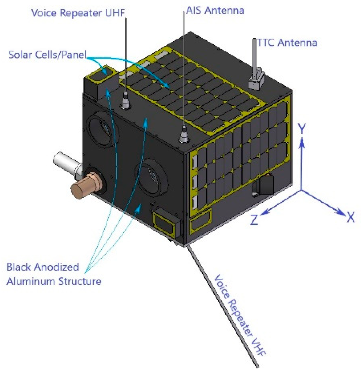
Specifically, in Indonesia, the space-based AIS has been installed on LAPAN-A2 microsatellite and was launched successfully in September 2015 [12]. This satellite has been developed and operated by National Institute of Aeronautics and Space of Indonesia (LAPAN) until the present day. This satellite was equipped with a space-based AIS module capable of collecting vessel messages from about 650 km altitude with a 6-degree inclination. The LAPAN-A2 microsatellite is a unique satellite since it was placed in equatorial orbit; hence, it is capable of monitoring Indonesian maritime territory and other equatorial countries 14 times a day. This condition is in line with the purpose of installing the AIS system that is to monitor vessel activity crossing Indonesian waters. Therefore, for Indonesia, which consists of 5.8 million square kilometers of marine territory, the existence of this satellite is beneficial, especially in terms of maintaining maritime surveillance. Besides space-based AIS payload, Automatic Package Reporting System (APRS), Voice Repeater (VR), and multispectral camera were also installed to this satellite in order to support amateur communication and remote sensing purpose [13]. The illustration of the LAPAN-A2 microsatellite and its mounted payloads is provided in Figure 1 below.
Since LAPAN-A2 is the first satellite designed by LAPAN that has brought AIS payload, advanced in-orbit research is needed in order to study the performance of the AIS payload. Various researches and experiments related to the performance of the AIS payload are carried out in order to design a better generation of space-based AIS systems in the future. The performance of a space-based AIS system represents its ability to collect vessel messages which can be observed from quantitative and qualitative aspects. Quantitative AIS performance can be measured by comparing the number of messages received by the space-based AIS system to another AIS system such as terrestrial-based AIS [14]. The other one, qualitative AIS performance, can be assessed by comparing the portion of valid messages to all received messages containing erroneous data [15].
In order to study the in-orbit performance of the LAPAN-A2 AIS system, in this paper, a quantitative LAPAN-A2 AIS performance in terms of message reception has been performed based on its AIS antenna orientation. Since LAPAN-A2 is also equipped with another payload, i.e., multispectral camera, in some cases, in order to point a camera lens to a specific target, the satellite has to be maneuvered into the desired angle. This maneuver will set the AIS antenna position to be oriented, causing a shift angle towards its default position. Since the difference in antenna orientation produces variations of covered ground area, we have hypothesized that satellite maneuver can affect the number of receive message and the message reception performance. Therefore, in this paper, the measurement of LAPAN-2 AIS receiver performance was carried out by varying the antenna orientation. Since this research is intended to study the impact of different AIS antenna orientations on its message reception performance, there is no ground truth or other AIS data involved in this research. This data may be required if one desires to compare LAPAN-A2 AIS performance to other AIS systems.
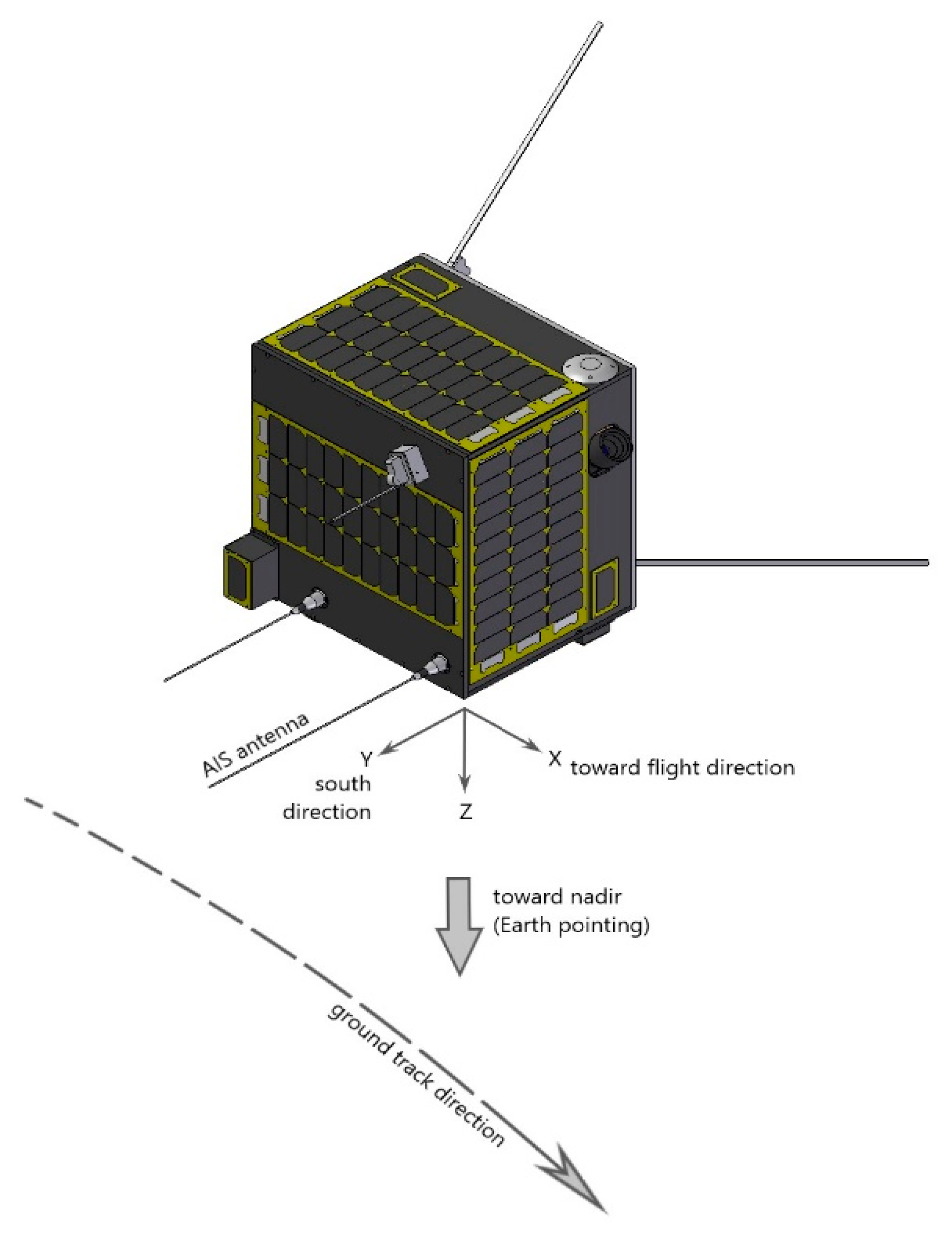
In case no specific maneuver is required, the LAPAN-A2 satellite is set to nadir pointing mode. In the nadir pointing mode, the spacecraft’s camera or z-axis is oriented to the center of the Earth, and this mode is defined as the nominal pointing of LAPAN-A2 satellite. During this nominal pointing, LAPAN-A2 AIS antenna is oriented to the south direction or 90° from its nadir direction. Since the antenna is mounted fixedly on the satellite’s body, to provide different antenna orientation, we have maneuvered the attitude of the satellite so that the AIS antenna will orient to 135° and 180° from nadir direction or 45° and 90° from its flight direction. All AIS messages collected during those maneuvers are analyzed and compared to messages collected in the nominal pointing (nadir pointing). The AIS datasets collected during the maneuvers are then analyzed to study the impact of antenna orientation on its reception performance quantitatively. The details of AIS antenna orientation and flight configuration are shown in Figure 2 below.
Finally, the result of this research is organized to produce an essential recommendation related to orienting and positioning the AIS antenna. Even though this research has been performed on LAPAN-A2 satellite, the result is suitable to be used as a reference by other typical small satellites which already exist in the orbit. Moreover, the result can also be used in determining the right AIS antenna position and orientation for any satellite being developed which plans to carry similar AIS antenna to LAPAN-A2 or other typical omnidirectional antenna.
2. Materials and Methods
2.1. AIS Satellite Antenna
The AIS satellite is typically small; a nano-sized or micro-sized satellite is suggested. The size limitation of the AIS satellite may cause a variety of problems that need to be addressed, and one of the main problems is the antenna placement. The small size of the satellite will limit the space and number of onboard antennas, which will further cause problems for communication. Smaller antennas lead to smaller power-to-noise ratios, and therefore reduced signal reception. For a nano-sized satellite, the reflector antennas are likely to require too much mass and volume and are therefore mostly ruled out as an option even though there is a nanosatellite using deployable Yagi-Uda type antenna [16]. Still there exists a variety of thin linear antennas suitable for this type of satellite. A short linear conductor is often referred to as a short dipole. The length of the conductor must be in the order of magnitude of the wavelength of the carrier for the antenna to function properly, and different conductor lengths result in different field patterns. Even though LAPAN-A2 is not a nanosatellite, it is a small satellite carrying multiple payloads; hence there is a space limitation to place the directional antenna or dual polarization antenna.
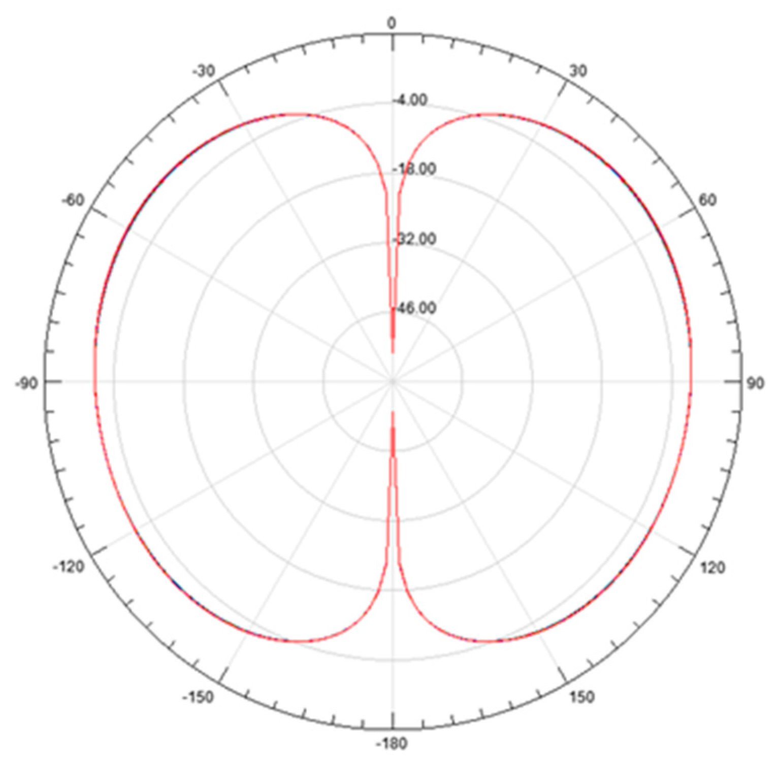
Figure 3 illustrates the field pattern for a vertically polarized single λ/4 dipole antenna. This λ/4 dipole antenna is used when there is not enough space in satellite body for a λ/2 dipole antenna. A conductor of λ/4 can act as the antenna, and the frame of the satellite can be impedance-matched to fit as the other half. The disadvantage of this technique is the reduction of efficiency by a factor of two, compared to the full-sized λ/2 antenna [17]. The polarization of the electromagnetic field, which is radiated by a dipole-transmitting antenna corresponds to the orientation of the antenna. A dipole antenna can be oriented horizontally, vertically, or at a slant. The receiver antenna is most sensitive to electric fields whose polarization is parallel to the orientation of the antenna. This means that a vertically polarized antenna will not be able to receive a horizontally polarized carrier. To compensate for this, a cross dipole might be an adequate solution. However, this type of antenna for a small satellite is typically difficult to accommodate. The signal loss due to polarization mismatch can be found by:
where ∆∂ is the polarization mismatch angle.
LpoldB = −20·log cos [(∆∂)]
Besides the polarization mismatch angle, AIS Satellite reception also suffers from atmospheric influence since the typical linear polarization AIS signal from the ships will pass the atmosphere to the satellite. The typical atmospheric influences, are Faraday rotation, Rain attenuation, and also Multipath distortion. The Faraday rotation is the changing or rotation of linear polarization due to ionospheric influence and is expressed by:
where e is a charge of an electron, m is the mass of an electron, c is the speed of light, and B is the magnetic flux density in the direction of propagation. The density of the electron is denoted as ne and may vary along with path d.
The choice of antenna technology can positively influence the probability of detecting an AIS message in a signal band with interference. This is accomplished by exploiting the following phenomena, which are related to the choice of antenna technology:
- Polarization diversity
- Frequency diversity (i.e., Doppler shift)
- Power diversity
- Geometric diversity (radiation pattern)
for the choice of antenna, various technology options are available. These include:
- Monopole/dipole
- Helix
- Yagi-uda
- Patch
The monopole/dipole antenna and the patch antenna offer linear polarization and are therefore able to introduce polarization diversity. The helix antenna suffers from a 3 dB gain loss due to polarization mismatch in addition to losing the benefit of polarization discrimination. LAPAN-A2 uses λ/4 antenna for its AIS receiver.
2.2. Details of Satellite Maneuver
The AIS receiver used in the LAPAN-A2 mission is a dual-channel VHF receiver, which can be tuned to any of the VHF channels in the maritime VHF band ranging from 156.025 to 162.025 MHz. When listening for AIS messages broadcasted on the two designated AIS channels, the radio is tuned to VHF channels 87B and 88B (161.975 and 162.025 MHz, respectively) [18].
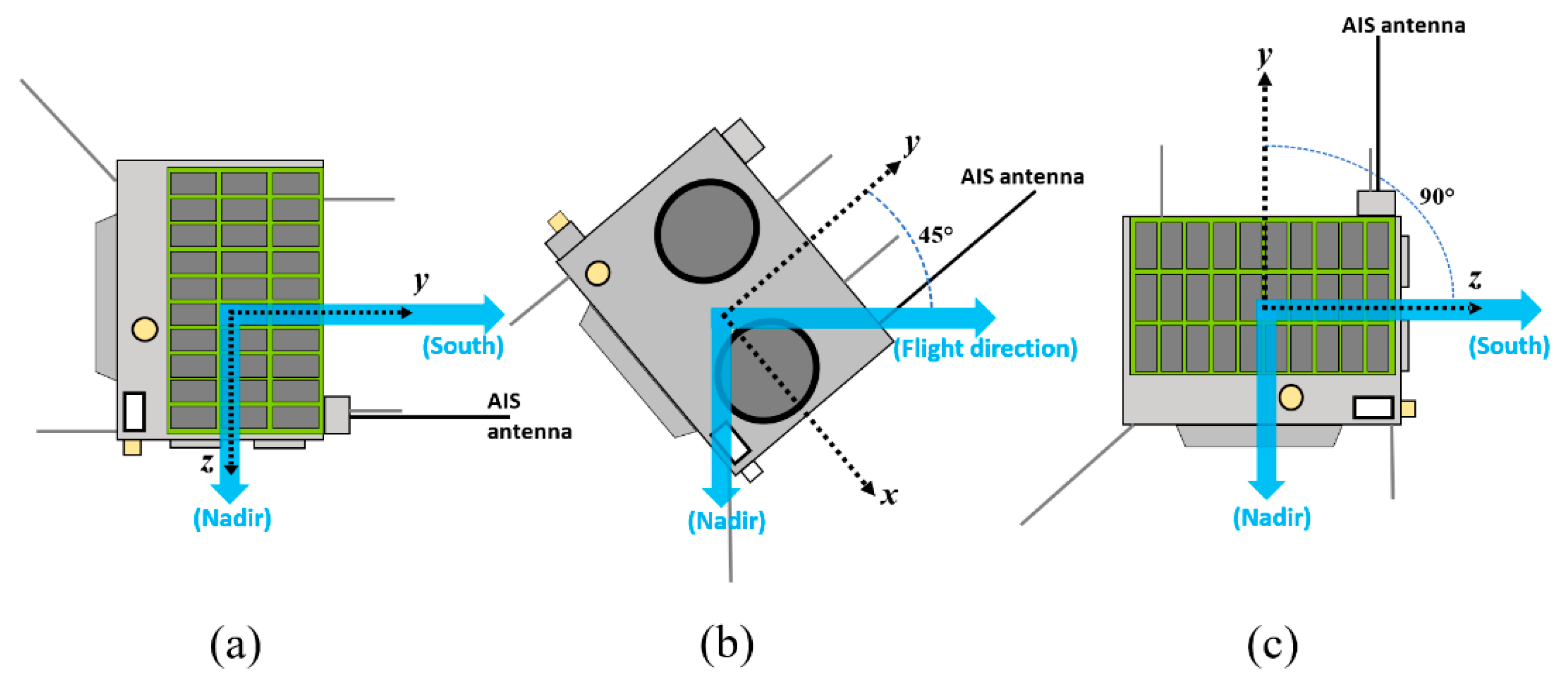
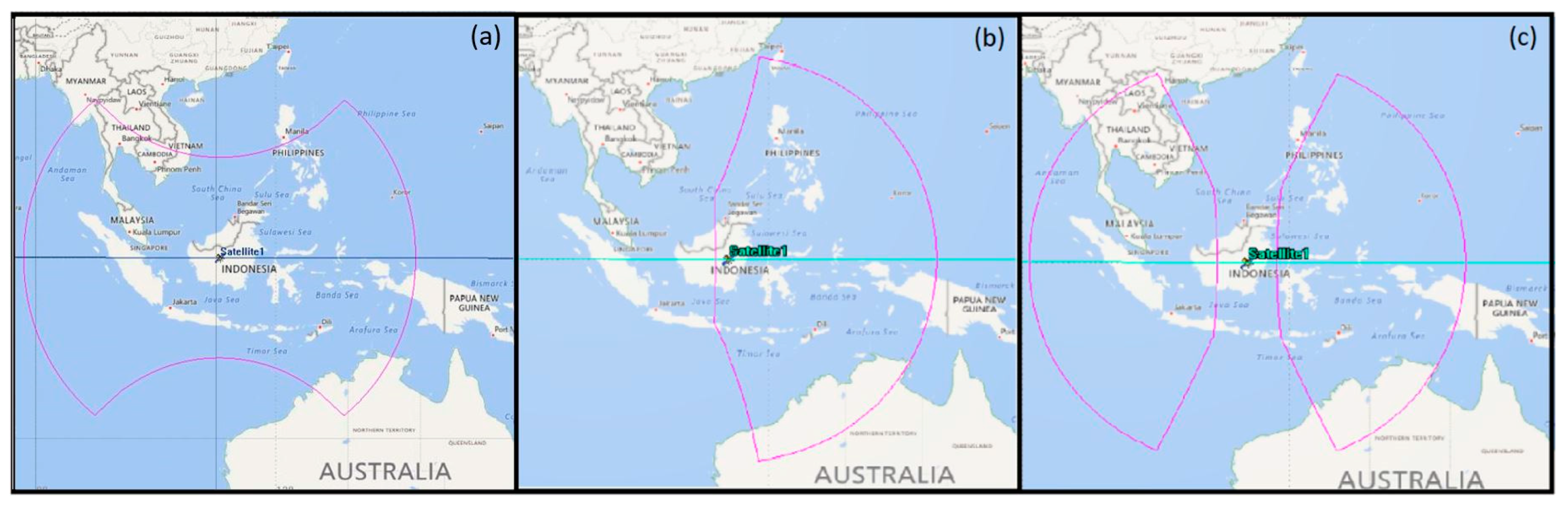
In this study, satellite maneuvering has been performed in order to orient the AIS antenna to the desired angle so the antenna will tilt 135° or 180° from the nadir axis. As depicted in Figure 4a, the flight configuration of nadir pointing is defined as a nominal condition. In this nadir pointing, the AIS antenna (that is placed on the y-axis) is oriented into south direction or 90° from its nadir axis. Based on Figure 4b, the spacecraft made a −90° maneuver on the x-axis and then −45° on the z-axis so the AIS antenna will tilt 45° from the flight direction or 135° from nadir. In the second setup (Figure 4c), the spacecraft only took a single −90° maneuver on the x-axis in order to orient the antenna 180° from the nadir axis. This orientation was chosen by considering that the different angle of monopole antenna could give different reception AIS signals from the ground.
For the consistency, in this paper, the flight configuration from the maneuver set up on Figure 4a–c respectively will be called as “nadir”, “45°-maneuvered” and “90°-maneuvered” and then the dataset resultant from the maneuver will be labeled as D0, D45, and D90, respectively. The “0”, “45”, and “90” notation is coming from the tilting angle between AIS antenna and certain reference axes (south or flight direction).
Figure 5 provides the typical pattern of monopole antenna in a different orientation toward the ground. It is shown that the antenna pattern of LAPAN-A2 during 90°-maneuver or the vertical antenna position has a broader area of detection compared to the nadir and 45°-maneuver configurations. The broader detection could lead to the increase of message reception; however, at the same time, it may have a collision problem of AIS signal [19]. By using the nadir, 45°-maneuvered, and 90°-maneuvered flight configurations, the AIS messages have been recorded and analyzed.
2.3. Analysis Method
As mentioned in the introduction, the aim of this research is not intended to study the impact of different antenna orientations on the quality of space-based AIS messages, but rather the quantity of the received messages with valid status data integrity. Therefore, in this research, we did not perform AIS message correction. Necessary correction of AIS messages can be performed by removing the wrong location reported messages, re-used MMSI (Maritime Mobile Service Identity) identifier, and out of view message [20]. All of those corrections have to be done in case to assess the quality of the AIS dataset received by an AIS receiver. Hence, the valid and non-valid data portions need to be calculated.
2.3.1. Data Preparation
In daily operation, in case no specific maneuver is required according to the mission, the orientation of LAPAN-A2 is set to default position i.e., nadir position, as provided in Figure 4a. In this condition, the continuous D0 dataset will be recorded as long as the AIS system is working properly. However, for the maneuvered condition (D45 or D90), the satellite maneuvering has been performed for a certain time range. After the maneuvering, a specific procedure was then applied in order to set the satellite back to its default position, i.e., nadir. Therefore, if the satellite maneuver is performed, three different AIS datasets will be the result. These datasets are related to the data recorded right before the maneuvering, during the maneuvering, and right after the maneuvering process. In the rest of this paper, the term “before”, “maneuver”, and “after” are related to the data recorded before the maneuvering, during the maneuvering, and after the maneuvering process, respectively.
Due to the power limitation to hold the satellite on its maneuver position, the duration of the maneuvering must be limited to 11 h only. Based on this limitation, a multi-maneuvering configuration cannot be executed sequentially to provide a continuous D90 dataset which is acquired right after the acquisition of D45. Therefore, since the comparison was only performed between the datasets acquired continuously, the comparison is only possible to be carried out between the D90 and D0 and between D45 and D0 datasets. The continuously acquired datasets are required since in this research, we also perform continuous ship tracking during the maneuvering period to observe the individual message reception performances of a particular ship.
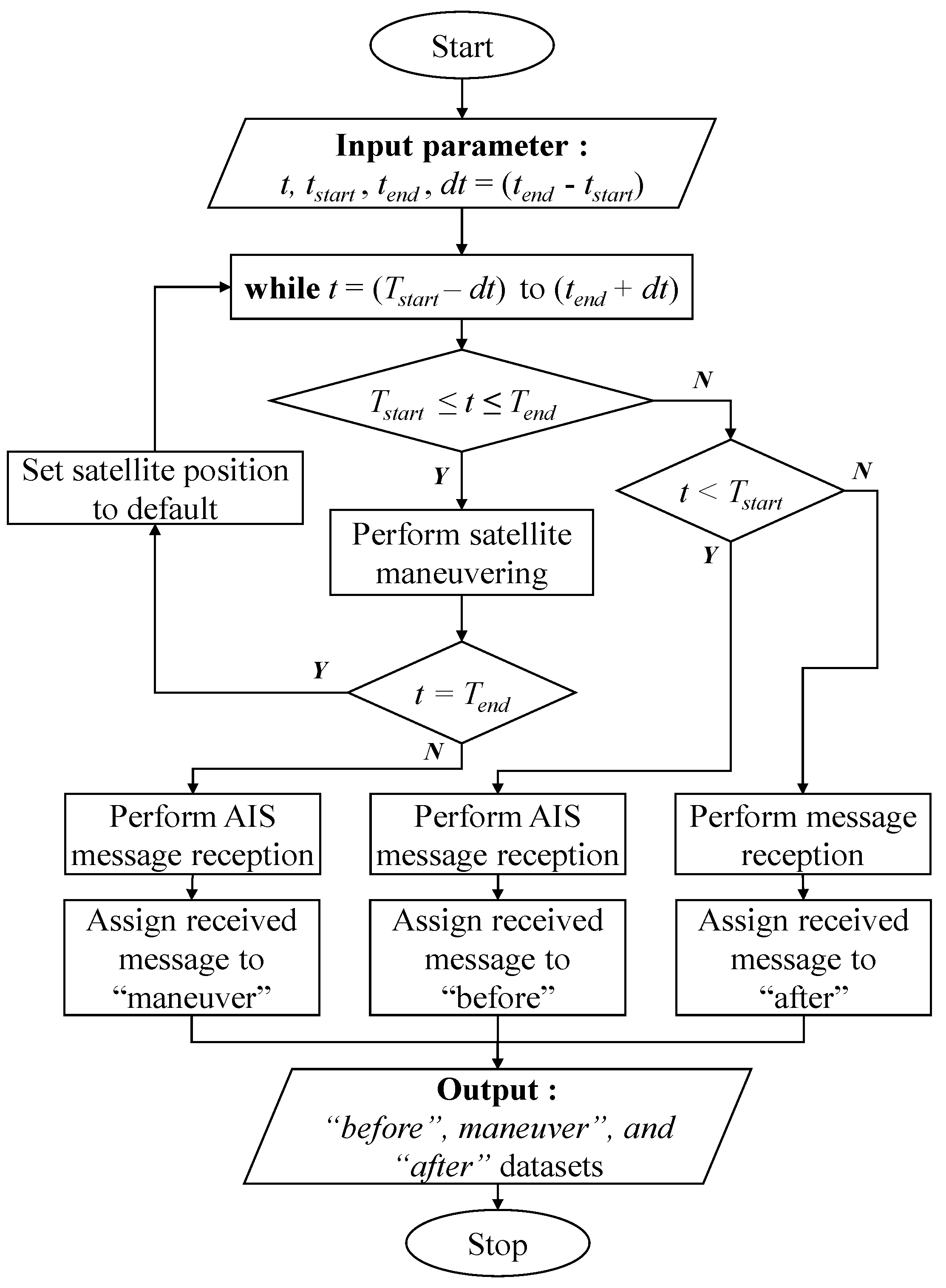
All of the datasets recorded under different antenna orientations will be compared to each other in order to study the impact of different antenna orientations to the message reception performance. In order to perform a fair comparison, the “before” and “after” datasets have been cut so that the acquisition time range of these datasets also equals to 11 h, similar to the duration of acquisition of “maneuver” datasets. Finally, a complete procedure performed to provide the necessary datasets on this research is shown in Figure 6. The term t in Figure 6 refers to the current satellite system time while tstart and tend refer to the desired start and stop time of satellite maneuvering.
It should be noted that the procedure presented in Figure 6 above was used to provide the necessary datasets recorded under the 45°-maneuvered or 90°-maneuvered conditions only. Therefore, different tstart and tend have been chosen and applied in order to provide all necessary datasets.
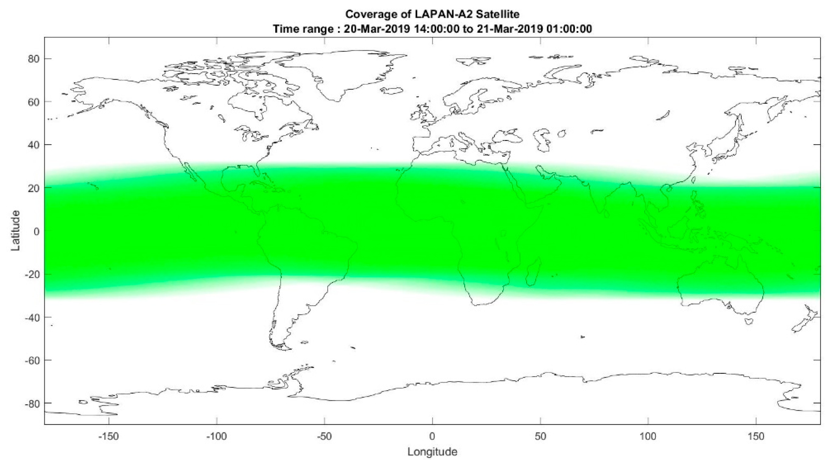
The complete tstart and tend values set to provide the necessary datasets used in this paper have been provided in Table 1. From Table 1, two sets of observations for each of the 45°-maneuvered and 90°-maneuvered configuration have been performed. For convenience, the 45°-maneuvered were labeled as “Run-3” and “Run-4” as stated under the “Task Name” column, while the 90°-maneuvered were labeled as “Run-1” and “Run-2”. We have found that one single set of observations consisted of 11 h of maneuvering, which is enough to provide representative datasets. This statement is based on the consideration that the observation is intended to be performed on the entire possible coverage area of LAPAN-A2 ranging from about −20° to 20° of latitude. Since LAPAN-A2 is an equatorial orbiting satellite, the ground area covered by this satellite in each pass is almost similar. However, because this satellite is orbiting at 6° inclination, it takes several passes to cover the entire possible coverage area of this satellite.
Based on our simulation, as provided in Figure 7 above, the 11-h duration, approximately 7–8 satellite passes, is enough to cover all the possible areas. Therefore, besides the power limitation issue, the 11-h maneuvering duration was also chosen because this duration gives enough time for the AIS receiver to receive all the vessel messages transmitted from the possible coverage area. In other words, in case the two sets of the observation cannot be performed, one set of observations can be used to produce valid analysis. In our case, the second observation is used in order to provide more complete datasets for analysis purposes.
Once the necessary datasets are available, an in-depth analysis involving the comparison of the number of received messages and unique MMSIs stored on “before”, “maneuver”, and “after” datasets has been performed. The comparison was also performed based on certain classes of AIS messages, which have been categorized based on Table 2. Therefore, our concern is not only to assess the overall message reception performance but also to observe the sensitivity of the AIS receiver to various AIS classes under different antenna orientations.
2.3.2. Individual Message Reception Performance
Besides comparing the entire number of messages which existed on each dataset, in this paper, we have also observed the change in the number of received messages of a particular ship as different satellite maneuvering is performed. This step was performed in order to assess the effect of satellite maneuvering on individual message reception performances of a moving ship. The assessment of individual message reception performances was carried by tracking a particular ship continuously before the maneuvering, during the maneuvering, and after the maneuvering stage. Practically, this assessment can be carried out by extracting the messages of the desired ship specified by its MMSI on “before”, “maneuver” and “after” datasets from corresponding maneuvering processes. The extracted messages are then ascendingly sorted based on acquisition time. By using these sorted messages, the ship‘s positions are then plotted and provided as a multi-temporal plot. For convenience, the number of messages received by a particular ship before the maneuvering, during the maneuvering, and after the maneuvering were also displayed on the plot.
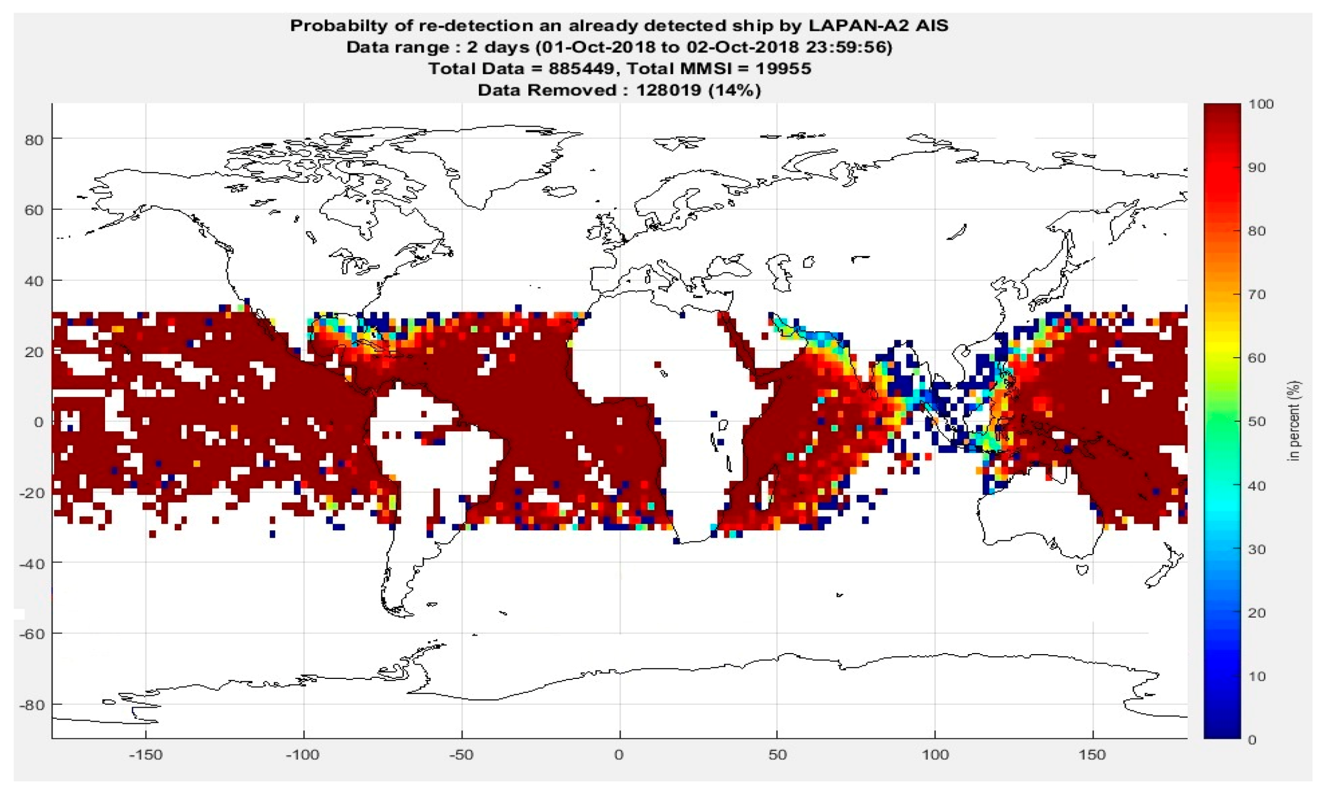
There are only a few ships which were assessed in terms of individual messages reception performance. These selected ships have been chosen since during the maneuvering period they were found in our area of interest. The area of interest has been assigned by employing the map of global tracking capability of LAPAN-A2 AIS receiver as the reference. The map was generated by employing the method proposed by Skauen, which was used to estimate the global tracking capability of space-based AIS using Norwegian AISSat-1 receiver [20]. The results of this method are based only on the data recorded by the space-based AIS sensors themselves without involving any ground truth data. The tracking capability represents the probability of re-detecting ships as they move around the globe and is explained to represent an upper bound on a space-based AIS system performance. In this work, a probability of re-detection map has been used as the reference as provided in Figure 8. This map was generated by using 2 days of the LAPAN-A2 AIS which dataset consisted of 19,955 unique vessels, from 1 October 2018, 00:00:00 UTC to 2 October 2018, 23:59:56 UTC. This dataset has been filtered in order to exclude the messages transmitted by re-used MMSI identifiers which can be recognized by its calculated speed exceeding 60 knots [20]. Based on this map, it is confirmed that the LAPAN-A2 AIS receiver is capable of producing an identical global tracking capability map compared to the map generated by Skauen, which is provided in his work.
By using the map provided in Figure 8 above, the area of interest has been set to the area having 50–60% and 80–100% of re-detection probability. The areas having 80–100% of re-detection probability are located on low traffic density, such as the Pacific Ocean, Indian Ocean, Arabian Sea and South American Ocean. Furthermore, the areas having 50–60% of re-detection probability are located on the transition region of the 80–100% and the high ship traffic density region, such as the Gulf of Mexico, Gulf of Oman and the ocean near the Philippines. The higher the tracking capability of an area, the higher the possibility to receive an AIS message transmitted by a ship in that area. Based on this definition, the tracking capability map was employed in order to observe the impact of maneuvering the antenna orientation to the message reception performance of an individual ship located on the area having a certain probability of re-detection value. Finally, from the number of received messages on a certain area of interest, the information regarding which antenna orientation has the better performance on that area for a particular ship will be discovered.
3. Results and Discussion
All datasets used in the comparison are produced by following the procedure provided in Figure 6 (Section 2.3.1). The complete properties of the AIS dataset collected under nadir and maneuvered conditions are shown in Table 1.
As shown in Table 1, for each maneuver, a total 33 h of continuous acquisition has been performed. The 33 h of duration was allocated to provide 11 h of acquisition before the maneuvering, during the maneuvering, and after the maneuvering, respectively. It is also shown that each maneuver was separated by different time distances, e.g., 2 days between Run-1 and Run-2 and 1 day between Run-3 and Run-4. This time separation has been chosen by considering other missions that have to be accomplished by LAPAN-A2 satellite. However, the existence of this separation is not an issue since the observation is not intended to be performed on a similar ship at all but rather to the ship on a similar location. Therefore, as long as the area covered by the satellite between the maneuvers is similar, the start and end time of the observation can be chosen freely. In addition, the problem might be faced if one uses overlapped datasets in which the message recorded in a dataset is re-used by another dataset.
3.1. AIS Messages Comparison
This section describes the comparison of total message number and unique MMSI received under nadir and maneuvered conditions. For detailed comparisons, each dataset has been categorized based on the AIS type messages according to the ITU definition [18]. The collection of AIS messages is categorized in Table 2.
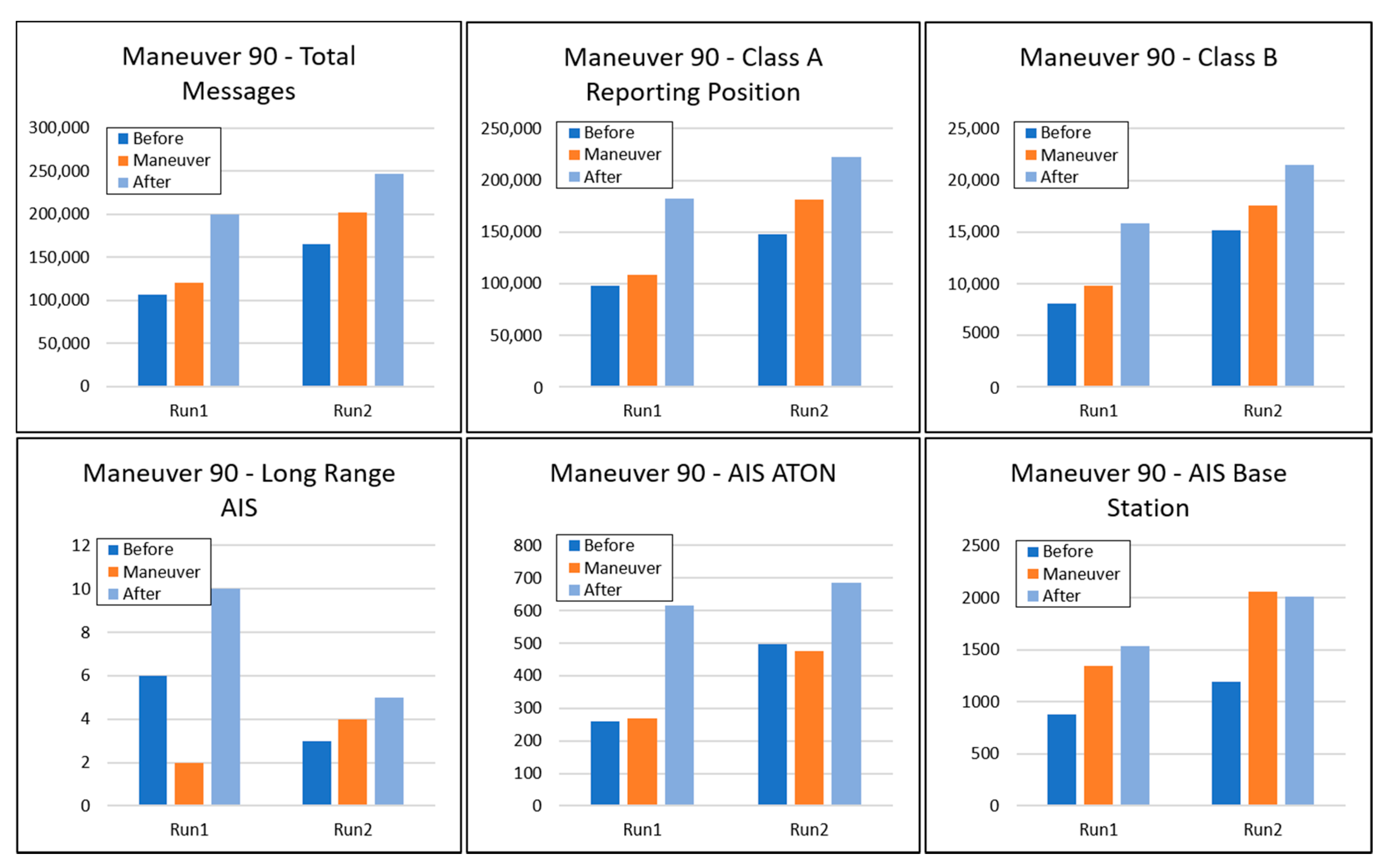
The resulting activity of before, during, and after the 90°-maneuver and 45°-maneuver, respectively, is shown in Figure 9 and Figure 10. Those figures consist of the comparison of total AIS messages and each categorized message according to Table 2 excluding Class A static and other messages. The exclusion of those types of messages is due to its low reception performance resulting in none of the received messages.
In Figure 9, it is shown that the total number of messages received during the maneuvering, i.e., D90, (orange bar) are not significantly improved compared to before the maneuvering, i.e., D0 (dark-blue bar). This trend is almost consistent with other categorized AIS data. This phenomenon could be understood since the antenna coverage patterns are quite similar while performing nadir and 90°-maneuvered, as provided in Figure 4a,c.
However, there is an interesting point that after the maneuvering (light-blue bar), the number of total received messages increases by about 29,07% on the average compared to during the maneuvering. We have investigated into the reason and found out that this condition is caused by the procedure used to set the satellite back to nadir after performing a certain maneuver. Before the maneuver, the current satellite flight configuration is nadir, as shown in Figure 4a. In case an operator wants to change the current configuration to 90°-maneuvered flight configuration, it just needs to perform a straight forward maneuver by rolling the satellite. Moreover, to achieve 45°-maneuvered from the current nadir flight configuration, the pitch and roll maneuver have to be performed. Changing satellite orientation from nadir to 45°-maneuvered or 90°-maneuvered flight configurations can be achieved during a single satellite pass period. However, based on satellite attitude information, bringing back the satellite attitude to precise nadir flight configuration from a maneuver condition needs several adjustments; hence, it can be completed for about two to three satellite pass periods due to the limited access of a ground station. In this transition time, the AIS antenna orientation varies ±10° towards its flight direction. As a consequence, after the maneuver, the satellite is not immediately set to its nadir flight configuration. Therefore, all of the AIS datasets acquired after the maneuvering consist of a higher number of AIS messages compared to the number of messages acquired before the maneuvering, since these datasets are acquired under the combination of nadir and maneuver flight configuration.
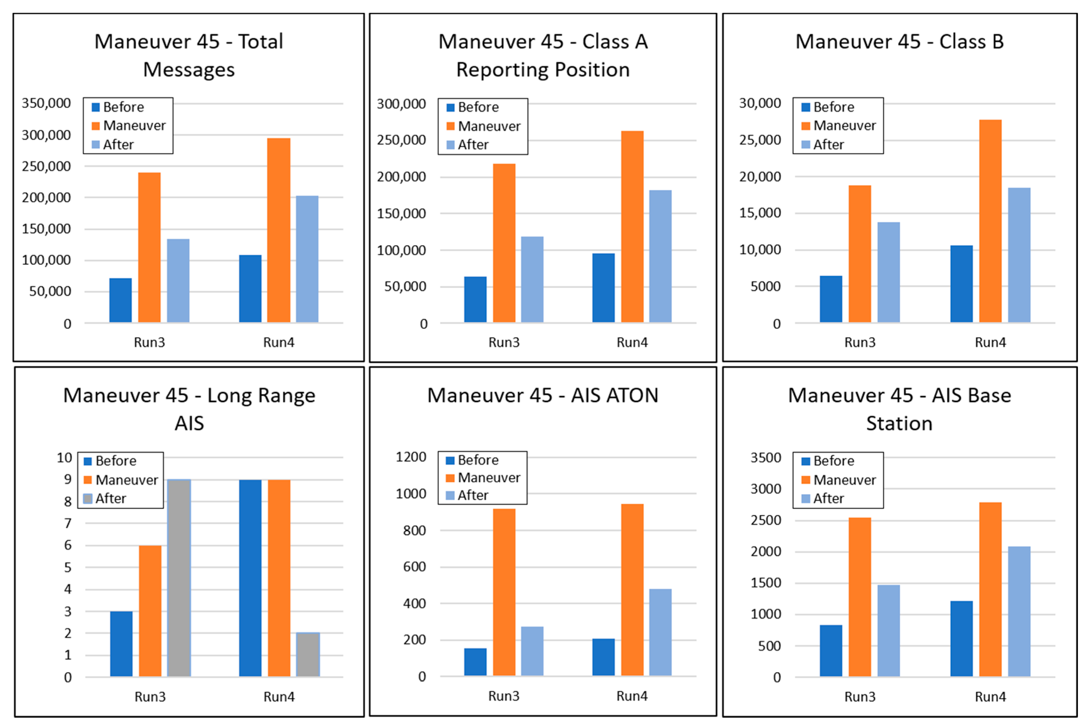
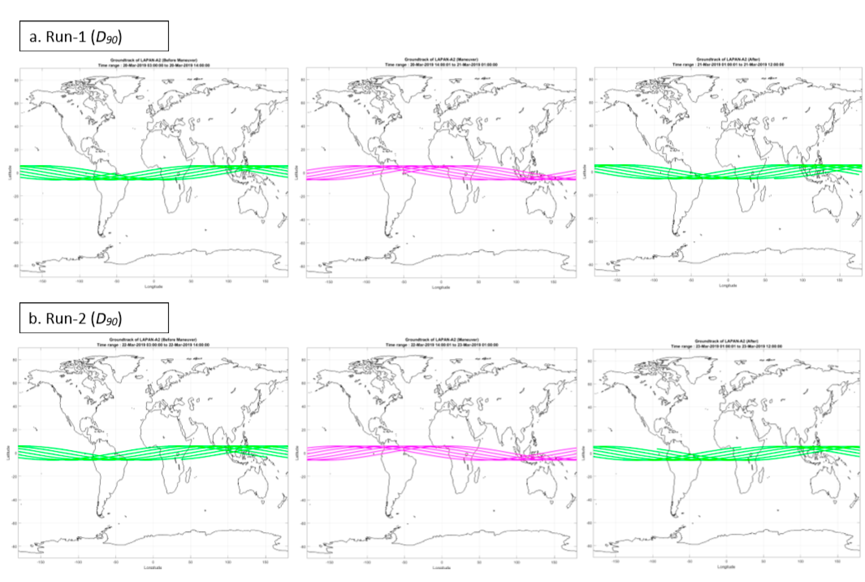
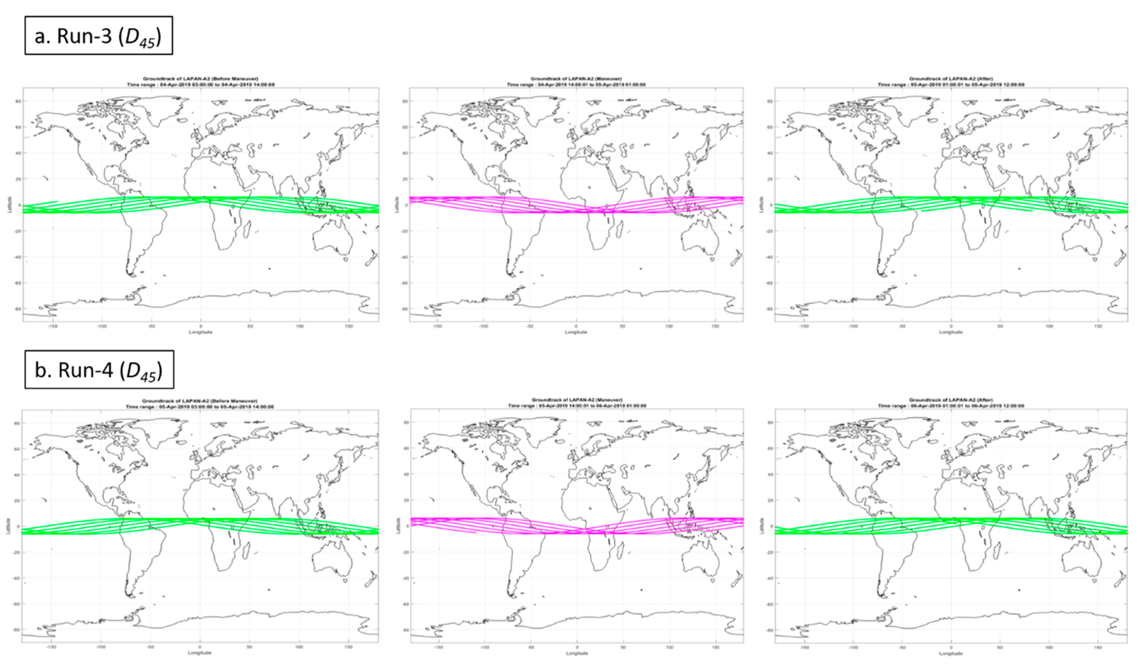
Based on Figure 10, it is confirmed that the performance of an AIS receiver during the 45°-maneuvered increases significantly compared to before and after the maneuver, except for Long-Range AIS messages type. For Long Range AIS on Run-3, although the 45°-maneuvered is capable of receiving a higher number of messages than before the maneuvering, this reception is still lower compared to after the maneuvering. On Run-4, the message reception of Long-Range AIS before the 45°-maneuvered is similar to the message reception during the 45°-maneuvered. We believe that the exception for Long Range AIS is caused by the small order of the number of received messages. Therefore, there is not enough data to make a statistically relevant conclusion. Excluding the Long Range AIS, the total number of messages received by making 45°-maneuvered increases around 31.11% to 239.29% compared to before and after the maneuver. One might have assumed that the increasing AIS message reception during the 45°-maneuvered and 90°-maneuvered is influenced by the different satellite ground track produced during the 11 h of maneuver. To deal with this assumption, the visualization of all ground tracks produced by the satellite during the observation is provided in Figure 11 and Figure 12.
The ground tracks provided in Figure 11 and Figure 12 were calculated during the 90°-maneuvered and 45-maneuvered observation period using the SGP4 algorithm [21]. It is shown that the ground tracks before the maneuvering, during the maneuvering, and after the maneuvering are quite similar; hence, it is assumed that the AIS message reception should be quite similar. This phenomenon eliminates the assumption and confirms that the increasing AIS message reception is purely influenced by satellite maneuvering.
3.2. Class A and B Composition
Besides analyzing the total number of received messages and other AIS data categories, in this work, an analysis to observe the impact of satellite maneuvering to the message reception of certain AIS classes has also been conducted. Because LAPAN-A2 receiver is capable of receiving both class A and class B types, in this case, we divide AIS message composition based on those two classes. Since the AIS message transmitted from a class A transponder will always be prioritized, the AIS message transmitted from a class B transponder will not be received until a slot on the AIS channel is available. Due to this schema, only a small portion of class B messages are recorded by the LAPAN-A2 space-based AIS receiver. This phenomenon can be used to study the effect of satellite maneuvering on AIS receiver sensitivity level on a small portion of AIS messages, i.e., class B AIS messages.
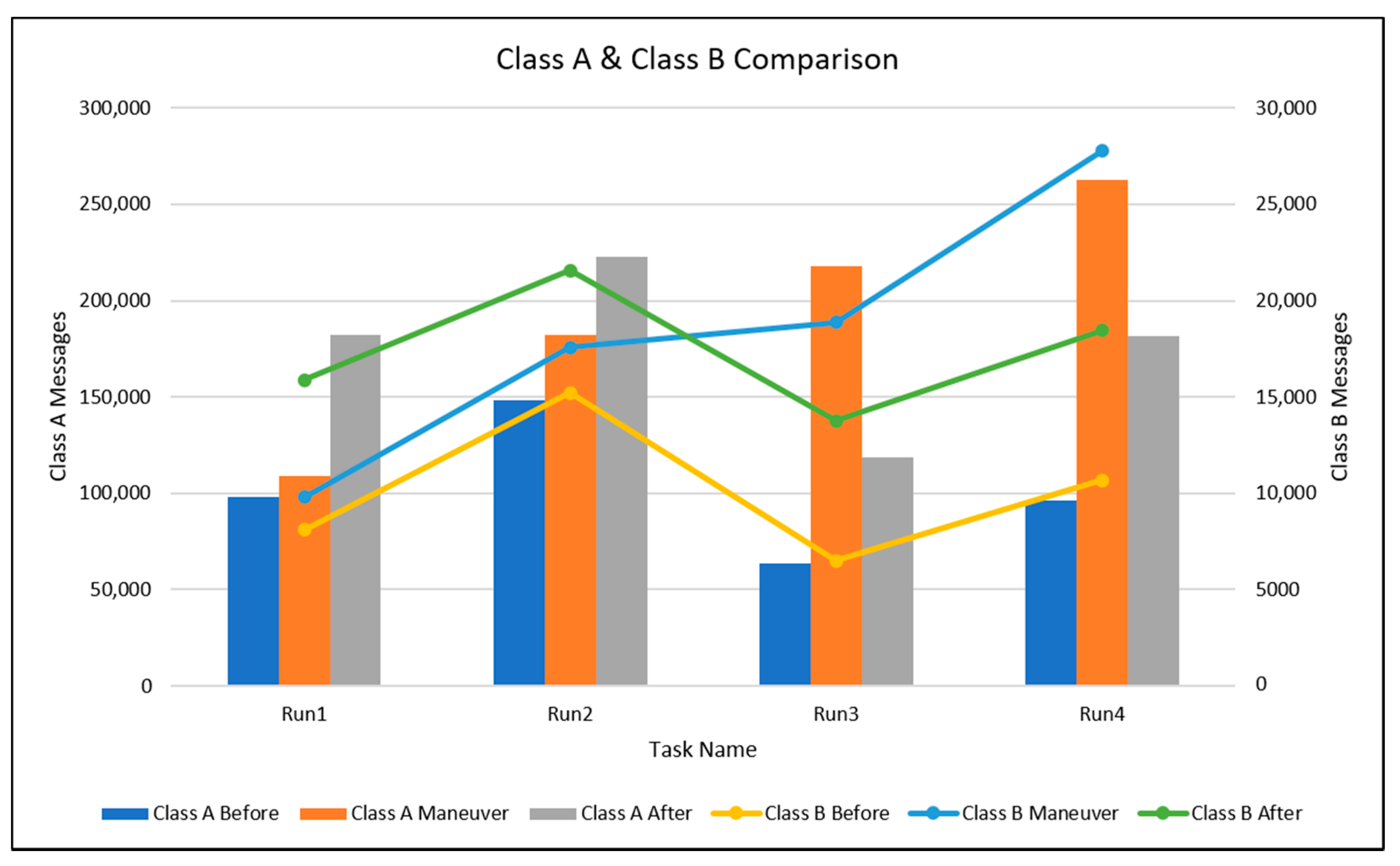
Practically, class B AIS messages can be recognized by their message identity (message ID) assigned by “18” and “19” values while the others can be classified into class A AIS. The total number of class A and class B messages received during the observation are provided in Figure 13.
Figure 13 shows that by using Run-1 and Run-2 datasets, the averaged message reception of class A AIS during the 90°-maneuvered is increasing by 17.17%, while for class B, the average message reception increases by 18.34% compared to before the maneuvering. It is also shown that Run3 & Run4 (45°-maneuvered) are capable of increasing the number of received class A & B messages. It is also confirmed that the averaged message reception is increasing by 208.80% and 175.93% for class A and B, respectively, compared to before the maneuvering. This condition indicates that by applying the 45°-maneuvered flight configuration, the LAPAN-A2 AIS receiver is capable of receiving more class A and class B AIS messages than the nadir flight configuration.
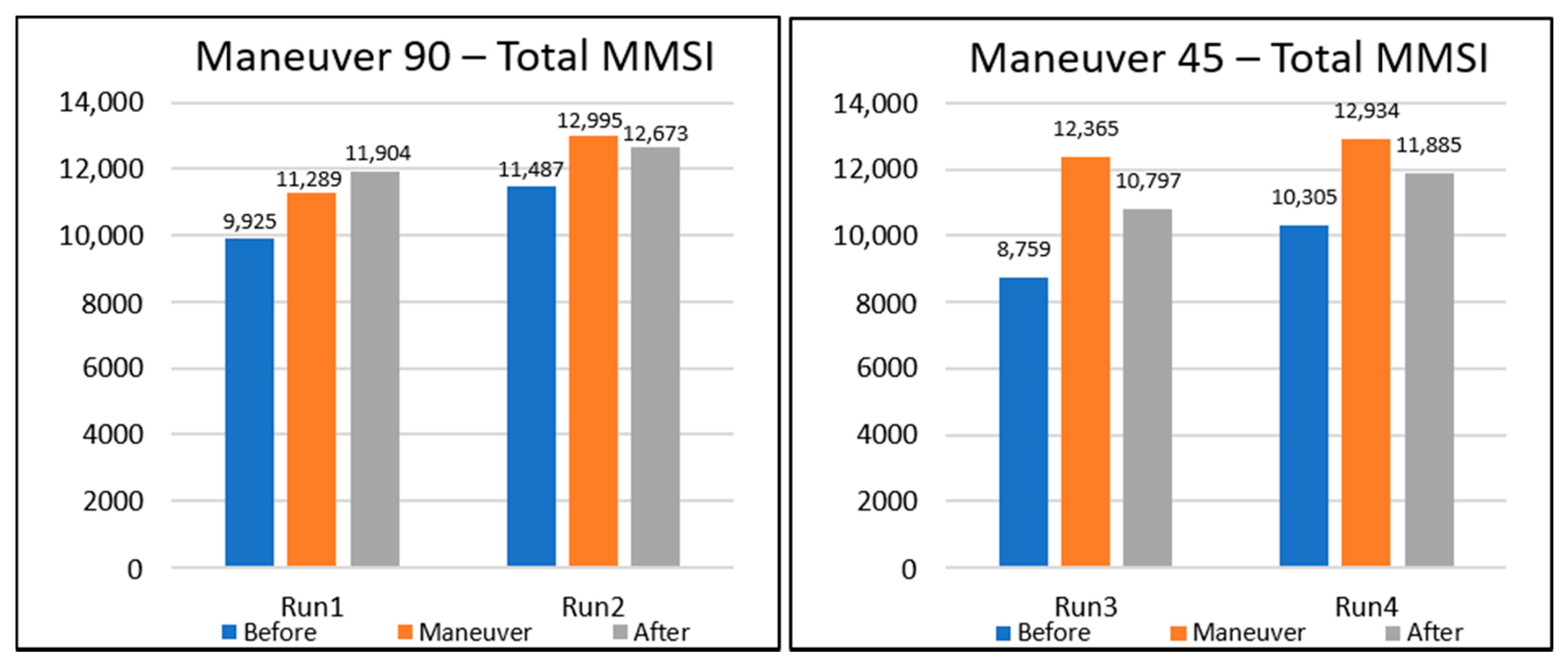
In this work, a filtering process was also performed in order to observe only unique MMSI detected during each maneuvering period. As shown in Figure 14, during the 45°-maneuvered, the averaged detection performance of unique MMSI is consistently increasing by a factor of 33.34% compared to before the maneuver. Whereas the 90°-maneuvered is capable of increasing the averaged detection performance of unique MMSI by a factor of 13.43% compared to before the maneuver. By comparing 45°-maneuvered and 90°-maneuvered, it can also be seen that 45°-maneuvered are better in overall AIS receiver performance.
We also notice that in all trials under 45°-maneuvered and 90°-maneuvered flight configurations, the detection performance after the maneuver gives a significant increase of AIS message detection compared to before the maneuver. However, 45°-maneuvered shows an overall increasing of MMSI number detection.
3.3. Individual Message Reception Performace
As described in the previous section, according to IMO regulation, several types of ships should transmit their AIS signals containing the status of their ship every several minutes. By using this positive assumption, we have also performed the ship tracking in order to observe the individual message reception performance of particular ships as explained in Section 2.3.2 by using the D0, D45, and D90 datasets. The ship tracking is required to assess the impact of different antenna orientations specified by its flight configuration to the number of the message received by the space-based AIS system. The visualization of the ship tracking results are provided in several figures below.
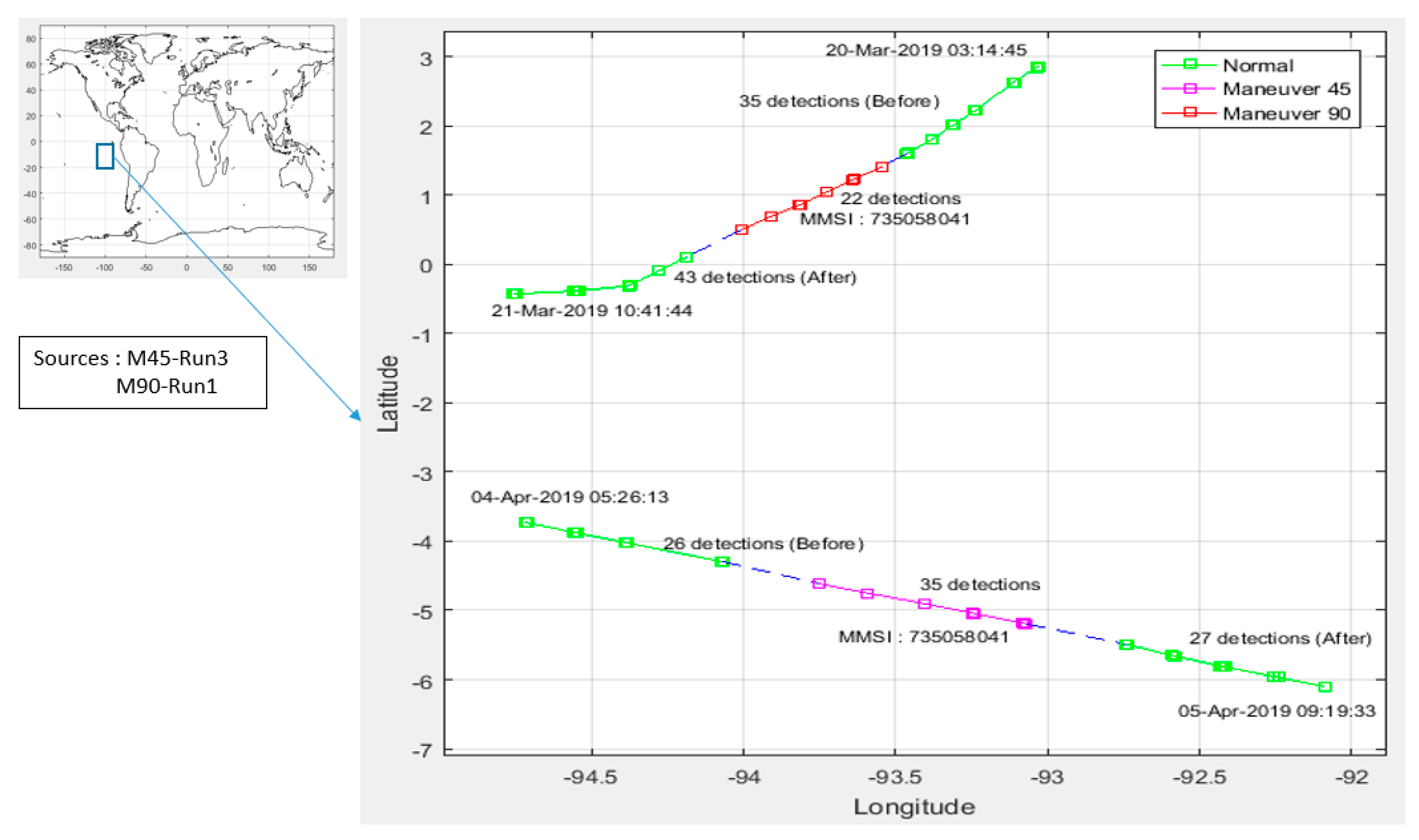
From Figure 15, it can be seen that a similar ship is detected in the South American Ocean having 100% re-detection probability. This ship has a different AIS message reception during the 45°-maneuvered and 90°-maneuvered observations. A ship with MMSI number 735058041, an Ecuador oil tanker ship, was detected 35 times before the maneuver, 22 times during the 90°-maneuver, and 43 times after the maneuver. At different times, this ship was detected 26 times before the maneuver, 35 times during the 45°-maneuvered and 27 times after the maneuver. From that data, the 45°-maneuvered is capable of providing higher message reception compared to the 90°-maneuvered and nadir flight configuration.
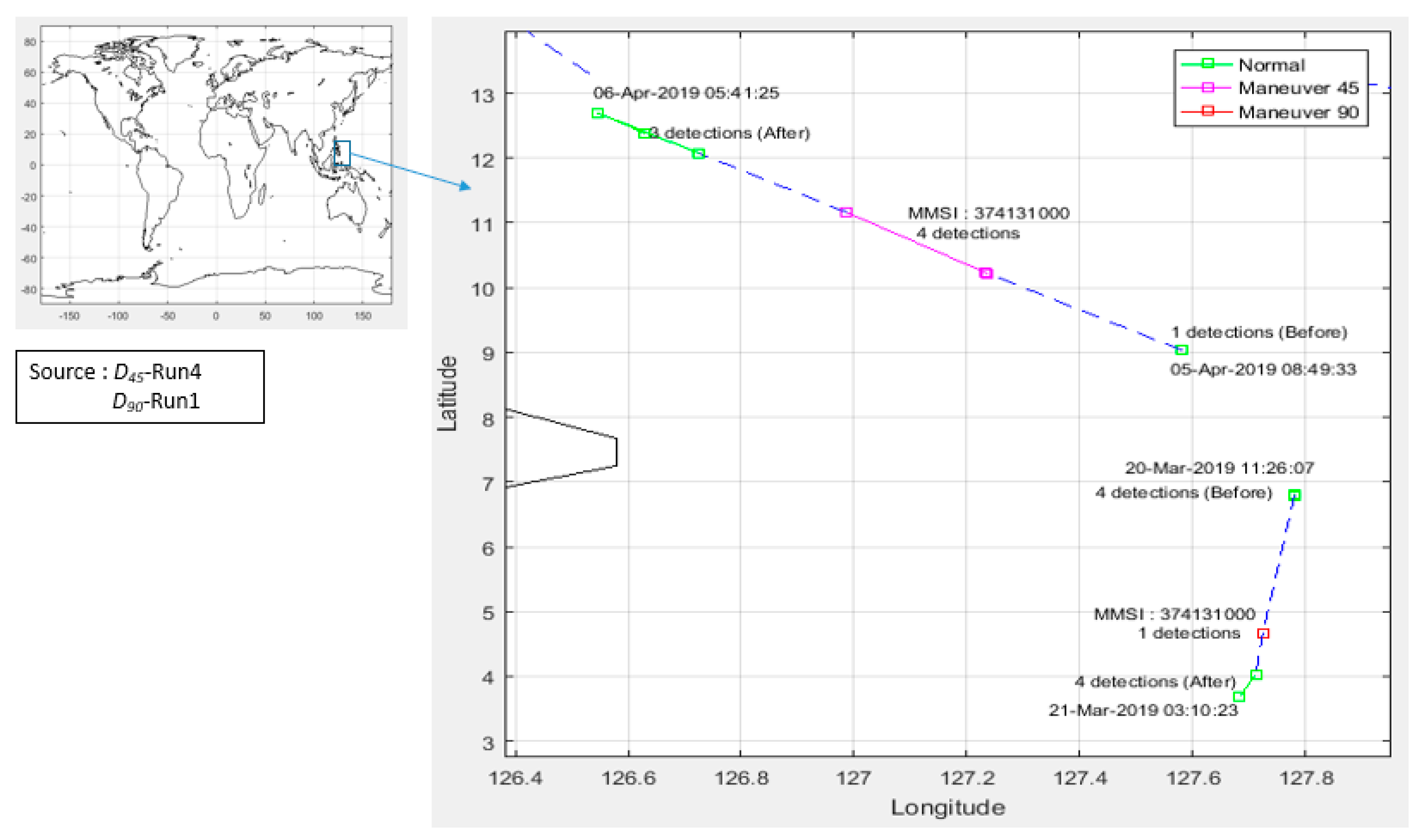
In Figure 16, in an ocean near the Philippines that has 50–60% re-detection probability, we also made a tracking of a class A ship with MMSI 374131000. This bulk carrier ship with a Panama flag was detected one time before the maneuver, four times during the 45°-maneuvered, and three times after the maneuver. This ship was detected four times before the maneuver, one time during the 90°-maneuvered and four times after the maneuver. According to this ship reception data, in the area that only has 50–60% re-detection probability, the 45°-maneuvered is also better than the 90°-maneuvered in terms of message reception performance.
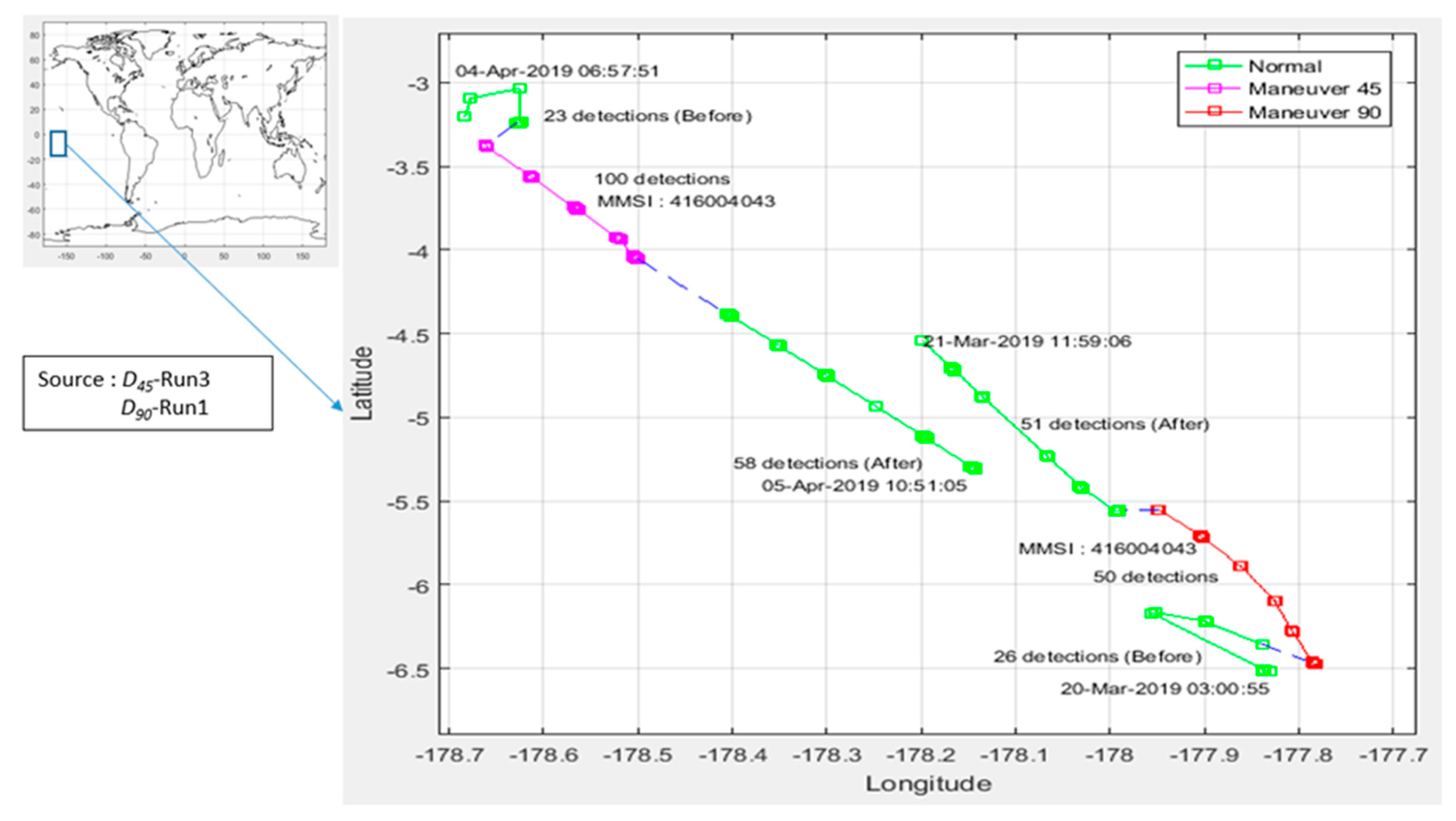
We have also performed some sampling of class B ships in the area which has 100% re-detection probability around the Pacific Ocean, as provided in Figure 17. Class B ship usually uses small transmit RF power, around 2 watts, so detection of this type of ship from space is a challenge. In the area of the Pacific with 100% re-detection probability, class B could be detected quite well. One sample of Taiwanese fishing ship with MMSI 416004043 has been detected 26 times before maneuver, 50 times during 90°-maneuvered, and 51 times after maneuver. This fishing ship has also been detected 23 times before maneuver, 100 times during the 45°-maneuvered and 50 times after the maneuver. According to this message reception data, in this case, the 45°-maneuvered leads to better performance compared to the 90°-maneuvered. This result may be caused by the effect of Faraday rotation of the AIS signal received in space. Furthermore, radio wave reflection from the seawater surface; & radiation pattern of ship-borne VHF antenna may fully match its radiation pattern with the satellite’s antenna [22]. The other way to increase the performance could be done by placing a directional antenna to narrow the coverage on a higher orbit satellite, especially in the equatorial region and also there is a study to develop 5-element dual-polarized array AIS antenna to provide full Earth coverage [23,24].
4. Conclusions
Within this paper, the analysis on the impact of varying the orientation of monopole λ/4 AIS antenna on its message reception performance has been presented. The analysis has been carried out by involving AIS datasets collected under 45°-maneuvered and 90°-maneuvered flight configuration applied on LAPAN-A2, an equatorial orbiting microsatellite. In this case, the 45°-maneuvered and 90°-maneuvered, respectively, refer to the satellite attitude configuration in which the antenna is oriented 45 and 90° towards the satellite flight direction. Based on the analysis over those datasets, it is confirmed that the highest message reception performance can be achieved by orienting the monopole λ/4 antenna 45° toward the flight direction. This antenna orientation gives a significant increase in overall AIS messages reception, including class A and class B type ships. From this finding, it is recommended for a small satellite or other satellite type carrying AIS payload to mount its monopole antenna orientation 45° towards its orbital flight direction.
Further study may be done by using other orientation angles or a combination of another type of antenna and different frequency. It also might be interesting to observe the performance of dual-polarization antennas for space-based AIS.
Author Contributions
This research contributed with the following contribution; conceptualization, W.H.; methodology; W.H.; software, K., W.H.; data curation; K., W.H.; validation, W.H., M.M., and U.R.; formal analysis, W.H., M.M., K., U.R.; visualization, W.H., K., and M.M.; supervision U.R.; writing—original draft, W.H., K.; writing—review and editing, W.H., K., M.M., and U.R.
Funding
This research received no external funding.
Acknowledgments
We would like to acknowledge the additional contribution from Satellite Operation Team in Satellite Technology Center, National Institute of Aeronautics & Space (LAPAN) Indonesia and also RF team that support this research.
Conflicts of Interest
The authors declare no conflict of interest.
References
- Goudossis, A.; Katsikas, S.K. Towards A Secure Automatic Identification System (AIS). J. Mar. Sci. Technol. 2019, 24, 410–423. [Google Scholar] [CrossRef]
- Natale, F.; Gibin, M.; Alessadrini, A.; Vespe, M.; Paulrud, A. Mapping Fishing Effort through AIS Data. PLoS ONE 2015, 6, e0130746. [Google Scholar] [CrossRef] [PubMed]
- Song, J.H.; Oh, K.R.; Kim, I.K.; Lee, J.Y. Application of Maritime AIS (Automatic Identification System) to ADS-B (Automatic Dependent Surveillance-Broadcast) Transceiver. In Proceedings of the International Conference on Control, Automation and Systems 2010, Gyeonggi-do, Korea, 27–30 October 2010; pp. 2233–2237. [Google Scholar]
- Harchowdhury, A.; Sarkar, B.K.; Bandyopadhyay, K.; Bhattacharya, A. Generalized Mechanism of SOTDMA and Probability of Reception for Satellite-based AIS. In Proceedings of the International Conference on Computers and Devices Communications (CODEC), Kolkata, India, 17–19 December 2012; pp. 1–4. [Google Scholar]
- Eriksen, T.; Skauen, A.N.; Narheim, B.; Helleren, O.; Olsen, O.; Olsen, R.B. Tracking Ship Traffic with Space-Based AIS: Experience Gained in First Months of Operations. In Proceedings of the International Water Side Security Conference, Carrara, Italy, 3–5 November 2010; pp. 1–8. [Google Scholar]
- Hassanin, A.; Läzaro, F.; Plass, S. An Advanced AIS Receiver using a Priori Information. In Proceedings of the OCEANS 2015, Genova, Italy, 18–21 May 2015; pp. 1–7. [Google Scholar]
- Plass, S.; Poehlmann, R.; Hermenier, R.; Damman, A. Global Maritime Surveillance by Airliner-Based AIS Detection: Preliminary Analysis. J. Navig. 2015, 68, 1195–1209. [Google Scholar] [CrossRef] [Green Version]
- Duffey, T.; Huffine, C.; Nicholson, S. On-Orbit Results from The Tacsat-2 ACTD Target Indicator Experiment AIS Payload. In Proceedings of the 4S Symposium —Small Satellites Systems and Services; European Space Agency (ESA): Rhodes, Greece, 26–30 May 2008; pp. 1–15. [Google Scholar]
- Trong, T.V.; Quoc, T.D.; Van, T.D.; Quang, H.P.; Nguyen, H. Constellation of Small Quick-Launched and Self-Deorbiting Nanosatellites with AIS Receivers for Global Ship Traffic Monitoring. In Proceedings of the Second Nanosatellite Symposium 2011, Tokyo, Japan, 14–16 March 2011; Available online: https://www.semanticscholar.org/paper/Constellation-of-small-quick-launch-and-with-AIS-Trong-Quoc/48290322963f2b34886e94af525c65a7dc10b021 (accessed on 2 June 2019).
- Harr, J.; Jones, T.; Andersen, B.N.; Eriksen, T.; Skauen, A.; Svenes, K.; Blindheim, E.V.; Ivar, I.S.; Beattie, A.; Bradbury, L.M.; et al. Microsatellites for Maritime Surveillance—An update on the Norwegian Smallsat Program. In Proceedings of the 69th International Astronautical Congress (IAC), Bremen, Germany, 1–5 October 2018; pp. 1–8. [Google Scholar]
- Kumar, C.; Kumar, M.; Srinivasan, V.V. Dual circularly polarized antenna system at VHF for AIS payload onboard Resourcesat-2. In Proceedings of the Conference: International Radar Symposium India (IRSI-11), Bangalore, India, 2–4 December 2011. [Google Scholar]
- Nugroho, J.T.; Zylshal; Chulafak, G.A.; Kushardono, D. Performance of LAPAN-A2 Satellite Data to Classify Land Cover/Land Use In Semarang, Central Java. In Proceedings of the IOP Conference Series: Earth and Environmental Science, Bogor, Indonesia, 26 October 2016; pp. 1–7. [Google Scholar]
- Syafrudin, A.H.; Hasbi, W.; Rahman, A. Camera Payload Systems for The LAPAN-A2 Experimental Microsatellite. In Proceedings of the Asian Conference on Remote Sensing, Bali, Indonesia, 20–24 October 2013; Volume 1, pp. 506–511. [Google Scholar]
- Li, S.; Chen, L.; Chen, X.; Zhao, Y.; Yang, L. Statistical Analysis of the Detection Probability of the TianTuo-3 Space-based AIS. J. Navig. 2017, 71, 1–15. [Google Scholar] [CrossRef]
- Iphar, C.; Napoli, A.; Ray, C. Detection of False AIS Messages for The Improvement of Maritime Situational Awareness. In Proceedings of the OCEANS 2015—MTS, Washington, DC, USA, 19–22 October 2015; Volume 34, pp. 1–7. [Google Scholar]
- Bradbury, L.M.; Diaconu, D.; Laurin, S.M.; Beattie, A.M.; Ma, C.; Spydevold, I.S.; Haugli, H.C.; Zee, R.E.; Harr, J.; Udnæs, F. NorSat-2: Enabling advanced maritime communication with VDES. Acta Astronaut. 2019, 156, 44–50. [Google Scholar] [CrossRef]
- Reiten, K.; Schlanbusch, R.; Kristiansen, R.; Vedal, F.; Nicklasson, P.J.; Berntsen, P.C. Link and doppler analysis for space-based AIS reception. In Proceedings of the 3rd International Conference on Recent Advances in Space Technologies, RAST 2007, Istanbul, Turkey, 14–16 June 2007; pp. 556–561. [Google Scholar]
- Recommendation ITU-R M.1371-3, Technical Characteristics for an Automatic Identification System Using Time Division Multiple Access in the VHF Maritime Mobile Band. 2007. Available online: https://www.itu.int/rec/R-REC-M.1371-3-200706-S/en (accessed on 1 June 2019).
- Narheim, B.; Olsen, O.; Helleren, O.; Olsen, R.; Beattie, A.; Zee, R. A Norwegian Satellite for Space-Based Observations of AIS in the High North. In Proceedings of the 22nd Annual AIAA/USU Small Satellite Conference, Logan, UT, USA, 11–14 August 2008. [Google Scholar]
- Skauen, A.N. Quantifying The Tracking Capability of Space-Based AIS Systems. Adv. Space Res. 2015, 57, 527–542. [Google Scholar] [CrossRef]
- Hoots, F.R.; Roehrich, R.L.; Kelso, T.S. Spacetrack Report No. 3—Models for Propagation of NORAD Elements Sets; Defense Documentation Center: Fort Belvoir, VA, USA, 31 December 1988; pp. 1–91. [Google Scholar]
- Ilcev, D.S. Analyses Of VHF-Band Multifunctional AIS Antenna. IIOAB J. 2017, 8, 145–151. [Google Scholar]
- Foged, L.J.; Giacomini, A.; Saccardi, F.; Tancioni, L.M.; Fonseca, N.J.G.; Di Cintio, A.; Della Pietra, G.; Caliumi, A.; Duchini, G.; Baracco, J.M. Miniaturized dual polarized VHF array element for AIS space application. In Proceedings of the 2013 IEEE Antennas and Propagation Society International Symposium (APSURSI), Orlando, FL, USA, 7–13 July 2013; pp. 980–981. [Google Scholar] [CrossRef]
- Mukhayadi, M.; Karim, A.; Hasbi, W.; Permala, R. Designing a Constellation for AIS mission based on data acquisition of LAPAN-A2 and LAPAN-A3 Satellites. Telkomnika Indones. J. Electr. Eng. 2019, 17, 1774–1784. [Google Scholar]
Figure 1.
Illustration of the LAPAN-A2 microsatellite.

Figure 2.
Nominal flight configuration of LAPAN-A2.

Figure 3.
The typical field pattern of a monopole λ/4 antenna.

Figure 4.
Illustration of LAPAN-A2 maneuvering configuration. (a) nadir, (b) 45°-maneuvered, (c) 90°-maneuvered.
Figure 4.
Illustration of LAPAN-A2 maneuvering configuration. (a) nadir, (b) 45°-maneuvered, (c) 90°-maneuvered.

Figure 5.
Typical antenna pattern of LAPAN-A2 AIS Antenna (a) nadir satellite attitude mode; (b) 45°-maneuvered; (c) 90°-maneuvered.
Figure 5.
Typical antenna pattern of LAPAN-A2 AIS Antenna (a) nadir satellite attitude mode; (b) 45°-maneuvered; (c) 90°-maneuvered.

Figure 6.
A complete step for providing the necessary dataset used to assess the impact of satellite maneuvering to message reception performance.
Figure 6.
A complete step for providing the necessary dataset used to assess the impact of satellite maneuvering to message reception performance.

Figure 7.
The footprint of the area covered by LAPAN-A2 during 11 h of the observation.

Figure 8.
The re-detection probability of LAPAN-A2 AIS generated using dataset acquired on 1 October 2018, 00:00:00 UTC to 2 October 2018, 23:59:56 UTC.
Figure 8.
The re-detection probability of LAPAN-A2 AIS generated using dataset acquired on 1 October 2018, 00:00:00 UTC to 2 October 2018, 23:59:56 UTC.

Figure 9.
Comparison of AIS message acquired under the 90°-maneuvered flight configuration.

Figure 10.
Comparison of AIS message acquired under the 45°-maneuvered flight configuration.

Figure 11.
The LAPAN-A2 satellite ground track produced during the 90°-maneuvered observation period.
Figure 11.
The LAPAN-A2 satellite ground track produced during the 90°-maneuvered observation period.

Figure 12.
The LAPAN-A2 satellite ground track produced during the 45°-maneuvered observation period.
Figure 12.
The LAPAN-A2 satellite ground track produced during the 45°-maneuvered observation period.

Figure 13.
Comparison of the number of received class A & B messages for each observation.

Figure 14.
Comparison of unique MMSI detection performance as 45°-maneuvered and 90°-maneuvered flight configuration applied on the satellite.
Figure 14.
Comparison of unique MMSI detection performance as 45°-maneuvered and 90°-maneuvered flight configuration applied on the satellite.

Figure 15.
Class A sample of ship tracking in an area of 100% re-detection probability.

Figure 16.
Class A sample of ship tracking in an area of 50–60% re-detection probability.

Figure 17.
Class B sample of ship tracking detection.


Table 1.
LAPAN-A2 satellite maneuver time.
| Task Name | Angle | Before | Maneuver | After | ||||
|---|---|---|---|---|---|---|---|---|
| Start | Stop | Start | Stop | Start | Stop | |||
| Run-1 | 90 | 20/3/2019 3:00 | 20/3/2019 14:00 | 20/3/2019 14:00 | 21/3/2019 1:00 | 21/3/2019 1:00 | 21/3/2019 12:00 | |
| Run-2 | 90 | 22/3/2019 3:00 | 22/3/2019 14:00 | 22/3/2019 14:00 | 23/3/2019 1:00 | 23/3/2019 1:00 | 23/3/2019 12:00 | |
| Run-3 | 45 | 04/4/2019 3:00 | 04/4/2019 14:00 | 04/4/2019 14:00 | 04/4/2019 1:00 | 04/4/2019 1:00 | 04/5/2019 12:00 | |
| Run-4 | 45 | 05/4/2019 3:00 | 05/4/2019 14:00 | 05/4/2019 14:00 | 06/04/2019 1:00 | 06/4/2019 1:00 | 06/5/2019 12:00 | |
Table 2.
Categorization of AIS message type.
| Data Categorization | Message Type |
|---|---|
| CLASS A POSITION REPORT | 1,2,3 |
| CLASS A STATIC | 5 |
| CLASS B | 18,19,24 |
| LONG RANGE AIS | 27 |
| AIS ATON | 21 |
| AIS BASE STATION | 4,10,11,20,23 |
| OTHER MESSAGES | 6,7,8,9,12,13,14,15,16,17,22,25,26 |
© 2019 by the authors. Licensee MDPI, Basel, Switzerland. This article is an open access article distributed under the terms and conditions of the Creative Commons Attribution (CC BY) license (http://creativecommons.org/licenses/by/4.0/).
Share and Cite
MDPI and ACS Style
Hasbi, W.; Kamirul; Mukhayadi, M.; Renner, U. The Impact of Space-Based AIS Antenna Orientation on In-Orbit AIS Detection Performance. Appl. Sci. 2019, 9, 3319. https://doi.org/10.3390/app9163319
AMA Style
Hasbi W, Kamirul, Mukhayadi M, Renner U. The Impact of Space-Based AIS Antenna Orientation on In-Orbit AIS Detection Performance. Applied Sciences. 2019; 9(16):3319. https://doi.org/10.3390/app9163319
Chicago/Turabian StyleHasbi, Wahyudi, Kamirul, Mohammad Mukhayadi, and Udo Renner. 2019. "The Impact of Space-Based AIS Antenna Orientation on In-Orbit AIS Detection Performance" Applied Sciences 9, no. 16: 3319. https://doi.org/10.3390/app9163319
Note that from the first issue of 2016, this journal uses article numbers instead of page numbers. See further details here.