Article

Towards Reconfigurable Electronics: Silicidation of Top-Down Fabricated Silicon Nanowires

1
Institute of Ion Beam Physics and Materials Research, Helmholtz-Zentrum Dresden-Rossendorf (HZDR), 01328 Dresden, Germany
2
International Helmholtz Research School for Nanoelectronic Network, HZDR, 01328 Dresden, Germany
3
Center for Advancing Electronics Dresden, Dresden University of Technology, 01062 Dresden, Germany
4
Institute of Physics, Chemnitz University of Technology, 09126 Chemitz, Germany
5
Fraunhofer Institute for Electronic Nano Systems, 09126 Chemnitz, Germany
6
Dresden Center for Nano-Analysis, Dresden University of Technology, 01062 Dresden, Germany
7
Fraunhofer Institute for Ceramic Technologies and Systems IKTS, Dresden, 01277 Dresden, Germany
8
Namlab gGmbH, Nöthnitzer Strasse 64, 01187 Dresden, Germany
9
Dresden Center for Computational Materials Science, Dresden University of Technology, 01062 Dresden, Germany
10
On leave of absence from the Institute of Electronics at Bulgarian Academy of Sciences, 72, Tsarigradsko Chausse Blvd., 1784 Sofia, Bulgaria
*
Authors to whom correspondence should be addressed.
Appl. Sci. 2019, 9(17), 3462; https://doi.org/10.3390/app9173462
Submission received: 30 June 2019 / Revised: 13 August 2019 / Accepted: 14 August 2019 / Published: 22 August 2019
(This article belongs to the Special Issue Silicon Nanowires and Their Applications)

Abstract

:

Featured Application

This work has implications for the fabrication of nickel silicide–silicon Schottky junction-based devices such as reconfigurable field-effect transistors.

Abstract

We present results of our investigations on nickel silicidation of top-down fabricated silicon nanowires (SiNWs). Control over the silicidation process is important for the application of SiNWs in reconfigurable field-effect transistors. Silicidation is performed using a rapid thermal annealing process on the SiNWs fabricated by electron beam lithography and inductively-coupled plasma etching. The effects of variations in crystallographic orientations of SiNWs and different NW designs on the silicidation process are studied. Scanning electron microscopy and transmission electron microscopy are performed to study Ni diffusion, silicide phases, and silicide–silicon interfaces. Control over the silicide phase is achieved together with atomically sharp silicide–silicon interfaces. We find that {111} interfaces are predominantly formed, which are energetically most favorable according to density functional theory calculations. However, control over the silicide length remains a challenge.

Graphical Abstract

1. Introduction

In the last few decades, the conventional downscaling of complementary metal-oxide-semiconductor (CMOS) transistors dominantly relied on the reduction of size to improve the performance as well as to reduce the costs and the power consumption of devices. With the end of physical scaling of field-effect transistors (FETs), further device performance enhancement is expected to be based on new concepts. These concepts include new materials (e.g., high mobility channel materials [1,2,3] such as 2D materials), metal gates with high-k gate dielectrics [4], new device architectures (e.g., 3D integration) [5], new computation principles (e.g., spintronics) [6], and new functionality (e.g., reconfigurability) [7]. Reconfigurability, in particular, can be achieved by selectively injecting a chosen type of charge carrier in the channel and controlling the concentration of these charge carriers at Schottky junctions [8]. This concept is typically implemented by fabricating Schottky junction-based FETs, also known as reconfigurable FETs (RFETs) [9]. In RFETs, undoped silicon nanowires (SiNWs) are nickel (Ni) silicided from both ends using annealing, and the Ni diffusion process creates a silicide–silicon–silicide structure with two Schottky junctions. The observed silicide phases vary in terms of the sheet resistance, Schottky barrier height, built-in strain etc. [10,11]. Hence, the phase of the silicide influences the performance of devices as the injection and the extraction of charge carriers in the silicide–silicon junction depend on the properties of the phase [12,13]. Since the performance of RFETs strongly depends on the quality of the Schottky junctions, proper control over the silicidation process (silicide phase, sharpness of the silicide–Si interfaces, silicide length along the nanowire) in these devices is very important but remains a challenge [14].
This work aims at understanding the Ni-silicide diffusion mechanism and attaining specifically the NiSi2 phase in top-down fabricated SiNWs by studying the silicide–Si interfaces. The formation of NiSi2–Si contacts is attractive because NiSi2 exhibits similar electron and hole barriers [10]. It also has a low lattice mismatch of 0.4% with respect to Si at room temperature, which allows the formation of single-crystalline structures [10,15]. NiSi2 forms an abrupt heterojunction to Si, thus enabling its use in unipolar devices such as RFETs [16]. To understand the sequence of phase formation within the desired temperature range, various studies have been reported for bottom-up grown nanowires [17,18,19,20,21,22,23,24,25,26,27,28,29,30,31]. However, fewer studies are available for top-down fabricated nanowires [32,33]. In addition to the formation of the suitable silicide phase, control over the sharpness of silicide–Si interfaces, and the silicide length is important for applications such as RFETs and Schottky barrier FETs [34].
Silicides are mostly formed by a temperature-induced interfacial reaction of a transition metal with Si. This process is called the reactive phase formation, which indicates diffusion between two adjacent phases leading to the formation of a single or multiple products along the chemical gradient between those phases [35,36]. Silicidation is governed by diffusion [37,38] and nucleation [35,39] and can be controlled by steps involved in the reaction phase formation.
Ni-silicide formation on bulk Si substrates has been extensively studied in the past [39,40,41,42,43]. Moreover, Ni-silicided nanowires can be produced by direct synthesis or by solid-state reaction of Ni with SiNWs. Wu et al. [44] reported single-crystalline NiSi nanowires produced by radial silicidation of vapor–liquid–solid grown SiNWs, which were coated with thermally-evaporated Ni and annealed at 550 °C in forming a gas atmosphere to produce single-crystalline NiSi NWs. The first report of the longitudinal growth of metal silicides in nanowires and the formation of flat and abrupt interfaces to silicon was given by Weber et al. [16] by the example of NiSi2–Si nanowire hetero-structures. Schmitt et al. [45] published a detailed review of several processes to produce transition metal silicide nanowires. The desired silicide phase formation is facilitated by proper control of annealing parameters [46] in an axial hetero-structure. These hetero-structures have been used for FET applications and exploration of innovative device concepts [8,16,45,47,48].
The silicide diffusion and phase formation in SiNWs has been described in various publications. Appenzeller et al. [29] demonstrated that the longitudinal growth of silicide in SiNWs is a function of the radius or the cross-sectional area of the nanowire and the produced silicide phase. The nature of the Si–silicide interface also influences the growth and the phase of silicide. The most common Ni-silicide phases in SiNWs are Ni2Si, NiSi, and NiSi2. The phase of silicide can be controlled by a proper choice of Ni quantity and quality [27,39], conditions of the reaction [30], strain in the nanowire [28,49], and crystal orientation of nanowires [26]. In <112> nanowires, the hexagonal θ-Ni2Si is formed at 300 °C, whereas this phase is not observed till 800 °C in bulk structures [47]. In <111> nanowires, first the epitaxial NiSi2 is formed and it withstands temperatures upto 700 °C. The low-resistive NiSi is formed at 700 °C [26]. The thermal history of the SiNW influences the silicidation rate. Yamashita et al. [50] presented a comparative illustration of silicidation rate for SiNWs fabricated by two different processes: The “doping first” process, where the annealing for dopant activation is carried out before the NW patterning; and the “patterning first” process, where NWs are patterned first and then subjected to further heat treatment for oxidation and dopant activation. They concluded that the silicidation rate in “patterning first” approach nanowires is higher than that for the “doping first” approach, as the oxidation induced strain in the “patterning first” approach is altered and distributed by dopant activation annealing in the later process step.
Here we present the results of our investigations on the Ni silicidation of top-down fabricated SiNWs. In the next section, details of the SiNW fabrication and the analysis techniques are given. The initial investigations were carried out on Si thin film structures to identify the process window for SiNW silicidation. In the third section, the results obtained from scanning electron microscopy (SEM) and transmission electron microscopy (TEM) are presented and compared to simulations. Results of electrical characterization of back-gated RFETs are also presented.

2. Materials and Methods

The devices were fabricated on (100) surface-oriented silicon-on-insulator (SOI) substrates. One set of substrates had a 20 nm top Si layer and a 102 nm buried SiO2 (BOX) layer, while the second set of substrates had a 50 nm top Si layer with a 110 nm BOX layer. SiNWs were fabricated using electron beam lithography (EBL) and inductively-coupled plasma (ICP) etching. EBL was performed with a Raith e-Line Plus system at an acceleration voltage of 10 kV, 1200 µC/cm2 dose, 30 μm aperture size, and with 2 nm area beam step size using the negative tone EBL resist, hydrogen silsesquioxane (HSQ) from Dow Corning (X-1541). HSQ is known to have sub 5 nm resolution and high etch resistance [51]. The original 6% HSQ solution was diluted to 2% concentration in methyl isobutyl ketone (MIBK) and spin coated at 2000 rpm for 30 s to yield a 40 nm thick HSQ layer. Then the samples were baked at 90 °C for 2 min and exposed using the EBL tool. After EBL, the samples were developed with a high-contrast tetramethylammonium hydroxide (TMAH) based development process [52] and dried with a N2 gun. The HSQ patterns were transferred into the top SOI layer using a SENTECH’s ICP-Reactive Ion Etcher SI 500. The parameters of the etching process were: ten standard cubic centimeters per minute (sccm) SF6, 20 sccm C4F8, 5 sccm O2, 0.9 Pa chamber pressure, 400 W ICP power, and 12 W RF power. After the SiNW fabrication, a second EBL-based patterning was performed for Ni contact formation using a positive tone resist, ZEP520A (ZEON Corporation, Tokyo, Japan). The exposure parameters were: A total of 10 kV acceleration voltage, 10 μm aperture size and area dose of 40 μC/cm2. The development was performed in n-amyl acetate solution (ZED-N50, ZEON Corp.). This was followed by baking at 200 °C for 5 min to smoothen the side walls of the patterned structures. Prior to Ni sputtering, the Si native oxide was etched away from NWs using 1% buffered hydrofluoric acid (BHF) solution and then the samples were transferred into the sputtering chamber. The sputtering was performed at 10 keV with a Gatan 681 High-Resolution Ion Beam Sputter Coater. The sample holder was rotated at a speed of 40 rpm for uniform deposition of Ni at a rate of 1.3 ± 0.2 Å/s. The thickness of Ni was varied between 35 and 50 nm according to the requirements of the experiments. After the sputtering step, lift-off was carried out in N-methyl-2-pyrrolidone (NMP) at 50 °C for 10 min. The samples were then rapid thermally annealed (RTA) at 450 °C in forming gas atmosphere (a mixture of 10% H2 and 90% N2) for silicidation of the NWs. The annealing time was varied in order to control the axial diffusion length of Ni into the SiNW. The role of the Ni pads was two-fold: Firstly, they acted as a Ni reservoirs for silicidation of NWs, and secondly, they served the purpose of a contact electrode.
To investigate silicidation of nanowires covered with an oxide shell, the samples were thermally oxidized. The oxidation process started with removal of the native oxide from the samples by dipping them in 1% BHF for 15 s. This was followed by an immediate transfer of samples in a pre-heated (875 °C) rapid thermal oxidation chamber. The samples were kept in the chamber for 10 min in the presence of an oxygen flow of 10 standard liters per minute (slm). Subsequently, the samples were annealed at 875 °C in a nitrogen environment for 5 min. This was followed by annealing in forming gas atmosphere. The oxidation process generates heavy stress in the nanowire due to the volume expansion. This impacts the oxygen diffusion in Si and the surface reaction rate at the Si–SiO2 interface drops. Therefore, the oxidation process is self-limited [53,54] (i.e., the stress generated by the oxidation process prevents further oxidation of the nanowires). After the oxidation of nanowires, a second EBL step for Ni contacts formation and subsequent annealing for silicidation was performed according to the aforementioned conditions.
To analyze the silicidation process, SEM and TEM investigations were performed. The systems used for SEM and TEM were Raith e-Line Plus and Zeiss Libra 200 TEM, respectively. TEM samples were prepared using focused ion beam (FIB) in a FEI Helios Nanolab 660 machine applying low-damage recipes to preserve the native crystal structure [55].

3. Results and Discussion

3.1. Silicidation in Si Thin Film Structures

To study silicidation in thin films structures, Si pads were patterned in Si substrates in <110> and <100> orientations using EBL and dry etching processes. Ni sputtering and subsequent annealing for silicidation was carried out according to conditions mentioned in Section 2. The purpose of this first study was to determine an initial process window for the nanowire silicidation. Figure 1 shows top-view SEM images of a sample after silicidation. Annealing was performed at 450 °C in forming gas atmosphere for 10 min. It is evident from the bright regions of the Si pads in Figure 1 that the Ni diffusion was not fast enough to reach the nanowires and it was confined within the Si pads. Moreover, the silicide–Si interface has different shapes in Si pads with <110> and <100> orientations. The silicide makes a 90° angle with Si in <110> orientation, whereas in the <100> orientation, the silicide has a step-like interface with Si.
TEM analysis was performed on lamellas, prepared by FIB, from the selected samples. The cross-section was inspected by high-resolution transmission electron microscopy (HREM) and electron energy loss spectrum (EELS). Figure 2 shows the overview of the cross-section with the different layers included in it. The top most sample layer is covered by a carbon protection layer, which is part of the FIB milling process to mitigate the damage incurred by FIB. Below the carbon layer, there are two Ni silicide layers and the Si substrate. The top Ni-containing layer depicts a Ni-rich silicide phase (region I). The following layer has a Si-rich silicide phase (region II). The interface between region I and II is smooth, whereas the interface between regions II and the Si substrate (region III) is rough and jagged. It is evident from Figure 2b–d that the silicide in region II has followed preferential crystal directions. The HRTEM image in Figure 3e shows an abrupt change in the silicide phase from NiS2 to Ni-rich phase.
To further investigate the silicidation process, zero-loss TEM was performed [56]. The images are presented in Figure 3. The Ni map shows higher concentration of Ni in region I compared to region II. Fast Fourier transform (FFT) confirms that the silicide phase in region II has a cubic lattice structure in accordance to NiSi2. The silicide in region I is Ni-rich and it has a non-cubic structure. The NiSi2–Si interface is atomically sharp (Figure 3c).

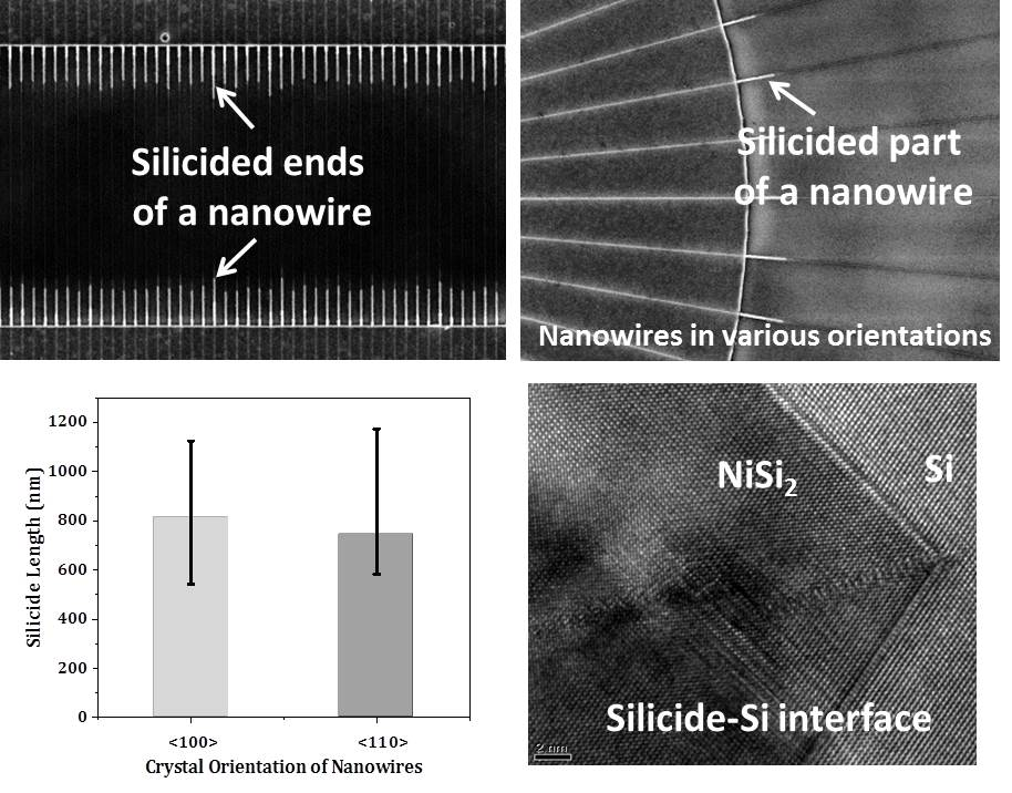
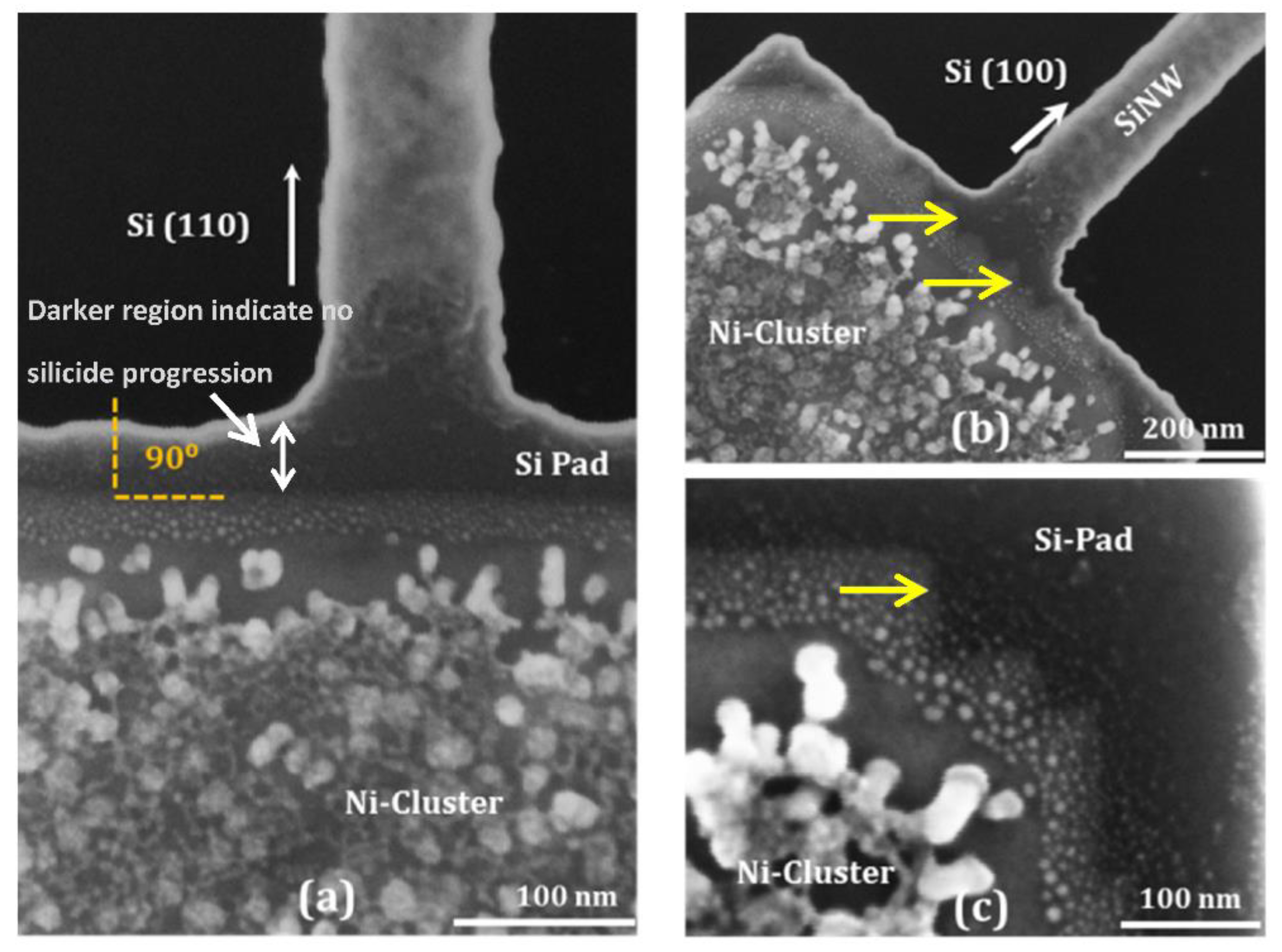
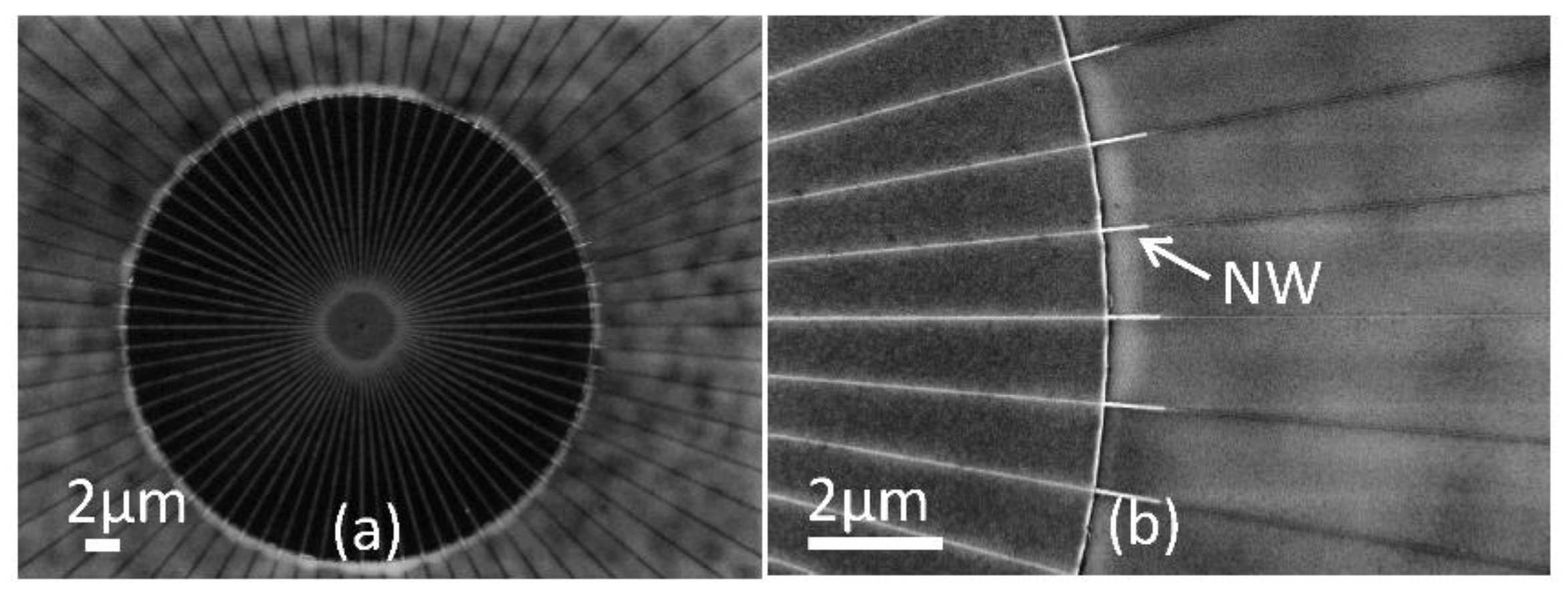
3.2. Silicidation in Nanowires

After determining an initial silicidation process window from the experiments for silicidation in thin film structures presented in the previous section, experiments for nanowire silicidation were performed. For these experiments, nanowires were fabricated in <100> and <110> crystallographic orientations using the top-down approach. Ni was sputtered according to the conditions described in the Materials and Methods section and, subsequently, rapid thermal annealing was performed at 450 °C in forming gas atmosphere for 80 s. The resulting structures are shown in Figure 4.
As illustrated in Figure 4, the silicide diffusion length is larger in <100> NWs compared to <110> NWs. Appenzeller et al. [29] have shown that silicidation diffusion length is inversely proportional to square of the diameter of the NW. The widths of <100> and <110> NWs in Figure 4a are 28 and 24 nm, respectively, while the silicide diffusion lengths are 745 and 628 nm, respectively. This shows a strong dependence of silicide length on the nanowire orientation. To investigate in detail the dependence of Ni diffusion and silicide formation on crystallographic orientations of NWs, a circular array of NWs with five-degree separation was fabricated. It was followed by the aforementioned steps for silicidation. The results are shown in Figure 5.
Although the silicide diffusion length varies in different crystallographic orientations of the NWs, it was not possible to extract a clear relation since the results vary in different arrays. To further investigate the orientation dependence of the silicide formation, silicidation of nanowire arrays fabricated in <100> and <110> crystallographic orientations was carried out and the results are presented in Figure 6a–d. The width of the NWs is 20 nm. The average silicide diffusion length in <100>- and <110>-oriented SiNWs is 812 and 744 nm, respectively (see Figure 6e). The images distinctly show that the diffusion of Ni and the silicide progression into the NWs of the same array is not homogeneous and on average has scattering of up to 300 nm in <100> and 400 nm in <110> NWs. Silicidation rates are known to vary based on different factors, including the quality of interface between the Ni reservoir and the NW [21]. However, our investigation shows this variation also within an array of NWs, which is processed under the same conditions. We attribute this variation in silicide length to different surfaces of NWs, as these NWs are top-down fabricated and their surfaces can be different due to the subtractive nature of the etching process. Because of this uncontrolled silicide formation and scattered positioning of the Schottky junctions, large top gates have to be placed to ensure that they properly cover the junctions at the two sides of the NWs [14,34]. This limits the possibilities for downscaling the size of devices and compromises their large-scale fabricability.
To have better control over the silicidation length, further investigations were carried out with sets consisting of two and three NWs. The results are shown in Figure 7. It was expected that the outer two NWs might consume excess Ni, giving a better control over the silicide progression in the central NW. However, it was still not possible to obtain a proper control over the silicide progression with this technique. The silicide diffusion length varied in different groups of NWs. Interestingly, the outer nanowires appear to exhibit a distinct silicide phase compared to the inner ones, as indicated by their higher brightness. While the inner NWs appear to have a NiSi2 phase with a comparable lattice constant to that of Si, the outer ones have Ni-rich phases with a larger lattice constant. This might be an effect of Ni source “competition” between neighboring nanowires. Apparently, the outer nanowires receive their Ni supply from a longer extent, thereby limiting that supply to the inner nanowires.
Dellas et al. [27] and Lin et al. [28] claimed that an oxide shell around the NWs hinders diffusion of silicide into the NWs. Therefore, expecting a better control, further investigations were made with oxidized NWs. However, it also resulted in non-uniform diffusion of silicide into the NW, as shown in Figure 8.

3.3. Properties of Silicide–Si Interface

To investigate the phase of the silicide and the quality of the silicide–Si interface, an exemplary NW was sectioned parallel to its length. Subsequently, HRTEM was performed. The resulting images are shown in Figure 9. Starting with Ni-rich phases near the Ni-reservoir, the Si fraction increases towards the silicide–Si interface.
HRTEM images show the formation of an atomically sharp Schottky junction, which is required for size downscaling and enhanced performance of the devices. FFT studies confirmed the formation of the desired NiSi2 near the silicide–Si interface. The interface orientation is {111} in accordance with [16].
In order to better understand our experimental observations, we calculated interface energies using density functional theory (DFT) as implemented in Atomistix ToolKit 15.1 [57]. The Perdew–Burke–Ernzerhof exchange-correlation function from [58] was used and the reciprocal space was sampled with a spacing of around 0.25 nm−1.
A periodic structure consisting of alternating silicon and NiSi2 was studied. The length of the resulting supercell perpendicular to the interface was at least 12 nm. Periodic boundary conditions were employed in the parallel directions. The atomic arrangements of the studied interfaces are described in [59]. In order to mimic our experimental setup of a nanowire lying on a substrate, the lattice constants in the silicon and NiSi2 regions were both fixed to the silicon lattice constant of the undisturbed silicon crystal. The atomic coordinates of all atoms within a 10 nm neighborhood around the interface were relaxed.
We defined the interface energy density as:
ϵ interface = ( E supercell N NiSi 2 E NiSi 2 N Si E Si ) / 2 A .
E supercell is the total energy of the calculated supercell, E NiSi 2 / Si are the total energies of bulk unit cells, and N NiSi 2 / Si follows from the number of unit cells in the supercell. A is the cross-section of the system and the factor 2 arises because two interfaces are included in a single supercell.
The calculation resulted in interface energy densities of around 2.2 eV/nm2 for the {111} interface (an A-type interface was assumed, see [59] for details) and around 4.2 eV/nm2 for the {110} interface. This effect is partially compensated by the higher area of a {111} interface in a <110> nanowire, because an angle of 35° between the normal vector of the interface and nanowire orientation occurs. For geometrical considerations, the interface area is increased by a factor of around 1.2 compared to a {110} interface. Hence, the total energy contribution of the interface is smaller for a tilted {111} interface, which makes such an interface energetically more favorable. The experimental observations of the {111} interface are; therefore, explained by the calculated interface energy densities.

3.4. Electrical Characterization of Fabricated Devices

To test the outcome of the silicidation process, electrical characterization of devices based on single unoxidized NWs patterned in both <100> and <110> orientations was carried out by back-gating. The back-gate voltage (Vbg) was swept between −40 to 40 V in a butterfly loop (0 to 40 V, 40 to −40 V, and −40 to 0 V). The drain to source voltage (Vds) was varied from 0.25 to 1 V. The devices exhibit large hysteresis as the nanowires are not passivated. We extracted a single sweep from the transfer characteristics, as illustrated in Figure 10. The minimum of the curves was shifted to left by 17 V to center the curves around 0 V. An ambipolar behavior of devices was found. The currents in <110>-oriented devices are higher compared to the currents in <100> devices. At Vds = 1 V, the values of n- and p- currents in <110> devices are 40.7 and 450.0 nA, while in <100> the values are 16.8 and 207.0 nA, respectively. The shift of original curves away from 0 V is attributed to a built-in potential on the NW surface in ambient conditions in the absence of passivation with, for example, an oxidation layer [34]. Unipolar behavior in these devices can be attained by using multiple gate electrodes [9], while p/n current symmetry, which is required for energy efficient functioning of circuits based on RFETs, can be tuned by oxidation induced stress [9,14].

4. Conclusions

In this work, we studied Ni silicidation of silicon thin films and top-down fabricated SiNWs by using the RTA technique. We paid special attention to the formation of the required silicide phase (NiSi2), the quality of the Schottky junctions, and the reproducibility of the silicide length along the nanowires, which are very important for device performance and scalability. To investigate the influence of the NW orientations on the silicidation process, SiNWs with different crystallographic orientations were silicided. Although large scattering in the silicidation lengths of nanowires was observed even for the nanowires of the same orientation, the silicidation in <100> nanowires is found to be faster than that in <110> nanowires. Furthermore, TEM and FFT analyses revealed the formation of sharp Schottky junctions with {111} interfaces and the NiSi2 phase of silicide required for the fabrication of RFETs. Density functional theory calculations showed that {111} interfaces are energetically favorable. Control over the diffusion length of silicide into the NW was not achieved. This makes placing of top gates on the Schottky junctions and downscaling of devices a challenge. Alternative annealing techniques with shorter annealing times, like, for example, flash lamp annealing, may be employed to have better control over the silicidation process. Transfer characteristics of the back-gated devices with single unoxidized NWs patterned in <100> and <110> orientations illustrate ambipolar behavior, with currents in <110>-oriented devices being higher compared to the currents in <100> devices.

Author Contributions

Conceptualization, D.D. and M.B.K.; methodology, D.D., M.B.K. and J.K. (device fabrication), F.F., S.G. and J.S. (simulations), M.L., S.B. and U.M. (lamella preparation and TEM); writing—original draft preparation, M.B.K., D.D. and F.F.; writing—review and editing, Y.M.G., M.L., F.F., S.G., J.S., A.E. and W.M.W.; supervision, A.E. and Y.M.G. All authors have read and approved this paper for submission.

Funding

We acknowledge funding by the Helmholtz Initiative and Networking Funds for support through the International Helmholtz Research School NanoNet via grant VH-KO-606 (M.B.K, D.D., F.F., S.B., W.M.W, S.G., J.S., A.E.) and the W2/W3 Programme for the first-time appointment of excellent female scientists via grant W2/3-026 (S.G., F.F.).

Acknowledgments

Authors thank Claudia Neisser and Tommy Schönherr for their help in conducting experiments. We are thankful to Habil Peter Zahn for his support in administrative affairs. We also thank Phanish Chava for his help in data compilation.

Conflicts of Interest

The authors declare no conflicts of interest.

References

  1. Yeo, Y.C.; Gong, X.; Van Dal, M.J.H.; Vellianitis, G.; Passlack, M. Germanium-based transistors for future high performance and low power logic applications. In Proceedings of the 2015 IEEE International Electron Devices Meeting (IEDM), Washington, DC, USA, 7–9 December 2015; p. 2. [Google Scholar]
  2. Dong, R.; Han, P.; Arora, H.; Ballabio, M.; Karakus, M.; Zhang, Z.; Shekhar, C.; Adler, P.; Petkov, P.S.; Erbe, A.; et al. High-mobility band-like charge transport in a semiconducting two-dimensional metal–organic framework. Nat. Mater. 2018, 17, 1027. [Google Scholar] [CrossRef]
  3. Wang, J.; Yao, Q.; Huang, C.-W.; Zou, X.; Liao, L.; Chen, S.; Fan, Z.; Zhang, K.; Wu, W.; Xiao, X.; et al. High Mobility MoS2 Transistor with Low Schottky Barrier Contact by Using Atomic Thick h-BN as a Tunneling Layer. Adv. Mater. 2016, 28, 8302–8308. [Google Scholar] [CrossRef] [PubMed]
  4. Chau, R.; Brask, J.; Datta, S.; Dewey, G.; Doczy, M.; Doyle, B.; Kavalieros, J.; Jin, B.; Metz, M.; Majumdar, A.; et al. Application of high-κ gate dielectrics and metal gate electrodes to enable silicon and non-silicon logic nanotechnology. Microelectron. Eng. 2005, 80, 1–6. [Google Scholar] [CrossRef]
  5. Arabi, K.; Samadi, K.; Du, Y. 3D VLSI: A Scalable Integration beyond 2D. In Proceedings of the 2015 Symposium on International Symposium on Physical Design, Monterey, CA, USA, 29 March–1 April 2015; pp. 1–7. [Google Scholar]
  6. Das Sarma, S.; Fabian, J.; Hu, X.; Žutić, I. Spin electronics and spin computation. Solid State Commun. 2001, 119, 207–215. [Google Scholar] [CrossRef] [Green Version]
  7. Risch, L. Pushing CMOS beyond the roadmap. Solid-State Electron. 2006, 50, 527–535. [Google Scholar] [CrossRef]
  8. Heinzig, A.; Slesazeck, S.; Kreupl, F.; Mikolajick, T.; Weber, W.M. Reconfigurable Silicon Nanowire Transistors. Nano Lett. 2011, 12, 119–124. [Google Scholar] [CrossRef]
  9. Heinzig, A.; Mikolajick, T.; Trommer, J.; Grimm, D.; Weber, W.M. Dually Active Silicon Nanowire Transistors and Circuits with Equal Electron and Hole Transport. Nano Lett. 2013, 13, 4176–4181. [Google Scholar] [CrossRef]
  10. Chang, Y.-J.; Erskine, J.L. Diffusion layers and the Schottky-barrier height in nickel silicide—silicon interfaces. Phys. Rev. B 1983, 28, 5766–5773. [Google Scholar] [CrossRef]
  11. Ottaviani, G.; Tu, K.N.; Mayer, J.W. Barrier heights and silicide formation for Ni, Pd, and Pt on silicon. Phys. Rev. B 1981, 24, 3354–3359. [Google Scholar] [CrossRef]
  12. Léonard, F.; Talin, A.A. Electrical contacts to one- and two-dimensional nanomaterials. Nat. Nanotechnol. 2011, 6, 773–783. [Google Scholar] [CrossRef]
  13. Larson, J.; Snyder, J. Overview and status of metal S/D Schottky-barrier MOSFET technology. IEEE Trans. Electron Devices 2006, 53, 1048–1058. [Google Scholar] [CrossRef]
  14. Simon, M.; Heinzig, A.; Trommer, J.; Baldauf, T.; Mikolajick, T.; Weber, W.M. Top-down technology for reconfigurable nanowire FETs with symmetric on-currents. IEEE Trans. Nanotechnol. 2017, 16, 1. [Google Scholar] [CrossRef]
  15. Bagdasarov, K.S.; Lube, É.L. Growth of Crystals; Springer: Boston, MA, USA, 1991; Volume 16, p. 278. [Google Scholar]
  16. Weber, W.M.; Geelhaar, L.; Graham, A.P.; Unger, E.; Duesberg, G.S.; Liebau, M.; Pamler, W.; Cheze, C.; Riechert, H.; Lugli, P.; et al. Silicon-Nanowire Transistors with Intruded Nickel-Silicide Contacts. Nano Lett. 2006, 6, 2660–2666. [Google Scholar] [CrossRef] [PubMed]
  17. Tang, W.; Dayeh, S.A.; Picraux, S.T.; Huang, J.Y.; Tu, K.-N. Ultrashort Channel Silicon Nanowire Transistors with Nickel Silicide Source/Drain Contacts. Nano Lett. 2012, 12, 3979–3985. [Google Scholar] [CrossRef] [PubMed]
  18. Tang, W.; Nguyen, B.-M.; Chen, R.; Dayeh, S.A. Solid-state reaction of nickel silicide and germanide contacts to semiconductor nanochannels. Semicond. Sci. Technol. 2014, 29, 054004. [Google Scholar] [CrossRef]
  19. Beregovsky, M.; Katsman, A.; Hajaj, E.; Yaish, Y. Diffusion formation of nickel silicide contacts in SiNWs. Solid-State Electron. 2013, 80, 110–117. [Google Scholar] [CrossRef]
  20. Chen, Y.; Huang, Y. Phase control in solid state silicide nanowire formation. Phys. Status Solidi 2013, 10, 1666–1669. [Google Scholar] [CrossRef]
  21. Yaish, Y.E.; Katsman, A.; Cohen, G.M.; Beregovsky, M. Kinetics of nickel silicide growth in silicon nanowires: From linear to square root growth. J. Appl. Phys. 2011, 109, 94303. [Google Scholar] [CrossRef] [Green Version]
  22. Ogata, K.; Sutter, E.; Zhu, X.; Hofmann, S. Ni-silicide growth kinetics in Si and Si/SiO2 core/shell nanowires. Nanotechnology 2011, 22, 365305. [Google Scholar] [CrossRef] [PubMed]
  23. Katsman, A.; Beregovsky, M.; Yaish, Y.E. Evolution of nickel silicide intrusions in silicon nanowires during thermal cycling. J. Appl. Phys. 2013, 113, 084305. [Google Scholar] [CrossRef]
  24. Dellas, N.S.; Abraham, M.; Minassian, S.; Kendrick, C.; Mohney, S.E. Kinetics of reactions of Ni contact pads with Si nanowires. J. Mater. Res. 2011, 26, 2282–2285. [Google Scholar] [CrossRef]
  25. Lu, K.-C.; Tu, K.N.; Wu, W.W.; Chen, L.J.; Yoo, B.-Y.; Myung, N.V. Point contact reactions between Ni and Si nanowires and reactive epitaxial growth of axial nano-NiSi/Si. Appl. Phys. Lett. 2007, 90, 253111. [Google Scholar] [CrossRef]
  26. Dellas, N.S.; Liu, B.Z.; Eichfeld, S.M.; Eichfeld, C.M.; Mayer, T.S.; Mohney, S.E. Orientation dependence of nickel silicide formation in contacts to silicon nanowires. J. Appl. Phys. 2009, 105, 94309. [Google Scholar] [CrossRef]
  27. Dellas, N.S.; Schuh, C.J.; Mohney, S.E. Silicide formation in contacts to Si nanowires. J. Mater. Sci. 2012, 47, 6189–6205. [Google Scholar] [CrossRef]
  28. Lin, Y.-C.; Chen, Y.; Xu, D.; Huang, Y. Growth of Nickel Silicides in Si and Si/SiOx Core/Shell Nanowires. Nano Lett. 2010, 10, 4721–4726. [Google Scholar] [CrossRef] [PubMed]
  29. Appenzeller, J.; Knoch, J.; Tutuc, E.; Reuter, M.; Guha, S. Dual-gate silicon nanowire transistors with nickel silicide contacts. In Proceedings of the 2006 International Electron Devices Meeting, San Francisco, CA, USA, 11–13 December 2006. [Google Scholar]
  30. Katsman, A.; Beregovsky, M.; Yaish, Y.E. Formation and Evolution of Nickel Silicide in Silicon Nanowires. IEEE Trans. Electron Devices 2014, 61, 3363–3371. [Google Scholar] [CrossRef]
  31. Chou, Y.-C.; Tang, W.; Chiou, C.-J.; Chen, K.; Minor, A.M.; Tu, K.N. Effect of Elastic Strain Fluctuation on Atomic Layer Growth of Epitaxial Silicide in Si Nanowires by Point Contact Reactions. Nano Lett. 2015, 15, 4121–4128. [Google Scholar] [CrossRef] [PubMed]
  32. Habicht, S.; Zhao, Q.-T.; Feste, S.F.; Knoll, L.; Trellenkamp, S.; Ghyselen, B.; Mantl, S. Electrical characterization of strained and unstrained silicon nanowires with nickel silicide contacts. Nanotechnology 2010, 21, 105701. [Google Scholar] [CrossRef]
  33. Habicht, S.; Zhao, Q.; Feste, S.; Knoll, L.; Trellenkamp, S.; Bourdelle, K.K.; Mantl, S. NiSi nano-contacts to strained and unstrained silicon nanowires. In Proceedings of the 2011 Materials for Advanced Metallization (MAM), Dresden, Germany, 8–12 May 2011. [Google Scholar]
  34. Pregl, S.; Weber, W.M.; Nozaki, D.; Kunstmann, J.; Baraban, L.; Opitz, J.; Mikolajick, T.; Cuniberti, G. Parallel arrays of Schottky barrier nanowire field effect transistors: Nanoscopic effects for macroscopic current output. Nano Res. 2013, 6, 381–388. [Google Scholar] [CrossRef]
  35. D’Heurie, F.M.; Lavoie, C.; Gas, P.; Philibert, J. Reactive Phase Formation: Some Theory and Applications. In Diffusion Processes in Advanced Technological Materials; Springer Science and Business Media LLC: Berlin, Germany, 2005; pp. 283–332. [Google Scholar]
  36. Laurila, T.; Molarius, J. Reactive Phase Formation in Thin Film Metal/Metal and Metal/Silicon Diffusion Couples. Crit. Rev. Solid State Mater. Sci. 2003, 28, 185–230. [Google Scholar] [CrossRef]
  37. Ohring, M. Chapter 1-A Review of Materials Science. In Materials Science of Thin Films, 2nd ed.; Academic Press: San Diego, CA, USA, 2002; pp. 1–56. [Google Scholar]
  38. Tu, K.-N. Silicon and Silicide Nanowires: Applications, Fabrication, and Properties; Pan Stanford Publishing: Redwood City, CA, USA, 2013. [Google Scholar]
  39. Koyama, M.; Shigemori, N.; Ozawa, K.; Tachi, K.; Kakushima, K.; Nakatsuka, O.; Ohmori, K.; Tsutsui, K.; Nishiyama, A.; Sugii, N.; et al. Si/Ni-Silicide Schottky junctions with atomically flat interfaces using NiSi2 source. In Proceedings of the European Solid-State Device Research Conference (ESSDERC), Helsinki, Finland, 12–16 September 2011; pp. 231–234. [Google Scholar]
  40. Iwai, H.; Ohguro, T.; Ohmi, S.-I. NiSi salicide technology for scaled CMOS. Microelectron. Eng. 2002, 60, 157–169. [Google Scholar] [CrossRef]
  41. Baglin, J.; Atwater, H.; Gupta, D.; D’Heurle, F. Radioactive Ni∗ tracer study of the nickel silicide growth mechanism. Thin Solid Films 1982, 93, 255–264. [Google Scholar] [CrossRef]
  42. Julies, B.A.; Knoesen, D.; Pretorius, R.; Adams, D. A study of the NiSi to NiSi2 transition in the Ni–Si binary system1. Thin Solid Films 1999, 347, 201–207. [Google Scholar] [CrossRef]
  43. D’Heurle, F. Diffusion in intermetallic compounds with the CaF2 structure: A marker study of the formation of NiSi2 thin films. J. Appl. Phys. 1982, 53, 5678. [Google Scholar] [CrossRef]
  44. Wu, Y.; Xiang, J.; Yang, C.; Lu, W.; Lieber, C.M. Single-crystal metallic nanowires and metal/semiconductor nanowire heterostructures. Nature 2004, 430, 61–65. [Google Scholar] [CrossRef] [PubMed]
  45. Schmitt, A.L.; Higgins, J.M.; Szczech, J.R.; Jin, S. Synthesis and applications of metal silicide nanowires. J. Mater. Chem. 2010, 20, 223–235. [Google Scholar] [CrossRef]
  46. Murarka, S.P. Chapter IV–Formation. In Silicides for Vlsi Applications; Murarka, S.P., Ed.; Academic Press: San Diego, CA, USA, 1983; pp. 99–131. [Google Scholar]
  47. Lavoie, C.; D’Heurle, F.; Detavernier, C.; Cabral, C. Towards implementation of a nickel silicide process for CMOS technologies. Microelectron. Eng. 2003, 70, 144–157. [Google Scholar] [CrossRef]
  48. De Marchi, M.; Sacchetto, D.; Frache, S.; Zhang, J.; Gaillardon, P.-E.; Leblebici, Y.; De Micheli, G. Polarity control in double-gate, gate-all-around vertically stacked silicon nanowire FETs. In Proceedings of the 2012 International Electron Devices Meeting, San Francisco, CA, USA, 10–13 December 2012; p. 8. [Google Scholar]
  49. Chen, Y.; Lin, Y.-C.; Zhong, X.; Cheng, H.-C.; Duan, X.; Huang, Y. Kinetic Manipulation of Silicide Phase Formation in Si Nanowire Templates. Nano Lett. 2013, 13, 3703–3708. [Google Scholar] [CrossRef]
  50. Yamashita, H.; Kosugiyama, H.; Shikahama, Y.; Hashimoto, S.; Takei, K.; Sun, J.; Matsukawa, T.; Masahara, M.; Watanabe, T. Impact of thermal history of Si nanowire fabrication process on Ni silicidation rate. Jpn. J. Appl. Phys. 2014, 53, 085201. [Google Scholar] [CrossRef]
  51. Mirza, M.M.; Velha, P.; Docherty, K.E.; Samarelli, A.; Ternent, G.; Zhou, H.; Li, X.; Paul, D.J. Nanofabrication of high aspect ratio (∼50:1) sub-10 nm silicon nanowires using inductively coupled plasma etching. J. Vac. Sci. Technol. B 2012, 30, 6. [Google Scholar] [CrossRef]
  52. Henschel, W.; Georgiev, Y.M.; Kurz, H. Study of a high contrast process for hydrogen silsesquioxane as a negative tone electron beam resist. J. Vac. Sci. Technol. B 2003, 21, 2018. [Google Scholar] [CrossRef]
  53. Liu, H.I. Self-limiting oxidation of Si nanowires. J. Vac. Sci. Technol. B 1993, 11, 2532. [Google Scholar] [CrossRef]
  54. Liu, H.I.; Biegelsen, D.K.; Ponce, F.; Johnson, N.M.; Pease, R.F.W. Self-limiting oxidation for fabricating sub-5 nm silicon nanowires. Appl. Phys. Lett. 1994, 64, 1383–1385. [Google Scholar] [CrossRef]
  55. Huang, J.; Loeffler, M.; Muehle, U.; Moeller, W.; Mulders, J.; Kwakman, L.; Van Dorp, W.; Zschech, E. Si amorphization by focused ion beam milling: Point defect model with dynamic BCA simulation and experimental validation. Ultramicroscopy 2018, 184, 52–56. [Google Scholar] [CrossRef]
  56. Reimer, L. Energy-Filtered Transmission Electron Microscopy; Springer: Berlin/Heidelberg, Germany, 1995. [Google Scholar]
  57. Atomistix ToolKit. 2015. Available online: https://www.synopsys.com/silicon/quantumatk.html (accessed on 16 August 2019).
  58. Perdew, J.P.; Burke, K.; Ernzerhof, M. Generalized Gradient Approximation Made Simple. Phys. Rev. Lett. 1996, 77, 3865–3868. [Google Scholar] [CrossRef] [PubMed] [Green Version]
  59. Fuchs, F.; Gemming, S.; Schuster, J. Electron transport through NiSi2–Si contacts and their role in reconfigurable field-effect transistors. J. Phys. Condens. Matter 2019, 31, 355002. [Google Scholar] [CrossRef] [PubMed]
Figure 1. Top-view scanning electron microscopy (SEM) images of silicon nanowires (SiNWs) with Si pads in (a) <110> and (b,c) <100> orientations. The silicided regions of the Si pads are brighter. Silicide–Si interface appears to be flat in <110> pads while in the case of <100> it has a step-like shape, as indicated by yellow arrows.
Applsci 09 03462 g001
Figure 2. Cross-sectional transmission electron microscopy (TEM) analyses of a lamella taken from the sample shown in Figure 1. (a) SEM top-view image of a SiNW with a Si pad. Focused ion beam (FIB) section was made along the white line to get the cross-sectional image of silicidation in the Si pad. (b) TEM image of the cross-section showing three different regions. Region I: Ni-rich Ni-silicide phase; Region II: Si-rich Ni-silicide phase; and Region III: pure Si from the Si pads. (c) Energy-filtered TEM (EFTEM) image of Ni to confirm its concentration in the three different regions. Higher brightness corresponds to higher concentration of Ni. (d) EFTEM image of Si of the same regions. Higher brightness corresponds to higher concentration of Si. (e) High resolution transmission electron microscopy (HRTEM) image of the interface between Region I and Region II, showing an abrupt change in the silicide phase.
Applsci 09 03462 g002
Figure 3. TEM analysis of silicide junctions. (a) Overview of inter-phases between Ni-rich phase and Si-rich phase. (b,c) Magnified images show atomically sharp NiSi2–Si junction.
Applsci 09 03462 g003
Figure 4. SiNWs in <110> and <100> crystallographic orientations: the brighter segments of NWs indicate silicide formation. Silicidation is faster in <100> NWs. Annealing is performed at 450 °C for 80 s.
Applsci 09 03462 g004
Figure 5. SEM images showing (a) nanowires fabricated in circular array with a five-degree separation to study the dependence of silicide diffusion length on the nanowire orientation; and (b) a higher magnification image showing clearly different diffusion lengths in different NWs. Annealing is performed at 450 °C for 80 s.
Applsci 09 03462 g005
Figure 6. SEM images showing silicidation flow in arrays of NWs fabricated in (a,b) <100> and (c,d) <110> crystallographic orientations. Large scattering of silicidation length is evident in NWs within each array. (e) Graph showing average silicide diffusion length (rectangular bars) and its scattering (linear “error bars”) in <100> and <110> SiNWs: silicide diffusion length is higher for <100> NWs, while large scattering is observed in both types of NWs. Annealing is performed at 450 °C for 80 s.
Applsci 09 03462 g006
Figure 7. SEM images of (a) single, (b) double, and (c,d) triple nanowires, showing uncontrolled silicidation. The outer nanowires in images (c,d) have Ni-rich silicide phase while the inner ones appear to have NiSi2. Annealing is performed at 450 °C for 10 min.
Applsci 09 03462 g007
Figure 8. SEM micrograph of silicidation of oxidized nanowires. Annealing is performed at 450 °C for 80 s.
Applsci 09 03462 g008
Figure 9. HRTEM images of silicide–Si Schottky junction: (a) NW sectioned along the NW length, (b) high magnification image of the interface showing an atomically-sharp Schottky junction, and (c) Fast fourier transform (FFT) studies confirm formation of NiSi2 phase near the silicide–Si interface. Annealing is performed at 450 °C for 80 s.
Applsci 09 03462 g009
Figure 10. Electrical characterization with back-gate sweeping of single NWs-based devices with (a) <110> and (b) <100> orientations. The devices show ambipolar behavior. To facilitate a p- and n-current comparison, curves were shifted left by 17 V to center. Currents in <110>-oriented devices are higher than those in <100>. Channel width and length for both types of nanowires are 20 nm and 3 µm, respectively.
Applsci 09 03462 g010

