Effect of Gap Flow on the Characteristics of Flow-Around and Flow-Induced Vibration for Two Circular Cylinders with Roughness Strips


Abstract
:1. Introduction
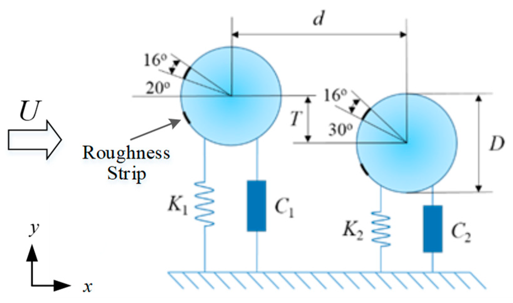
2. Physical Model
3. Mathematical Model and Numerical Calculation
3.1. Governing Equations
3.2. Equation of Motion
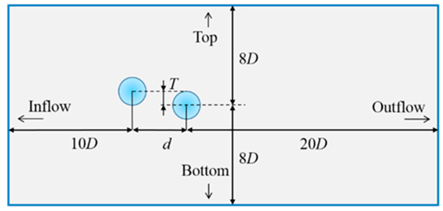
3.3. Computational Domain and Grid Generation
3.4. Model Validation
4. Results and Discussion
4.1. Flow around Two Stationary Cylinders
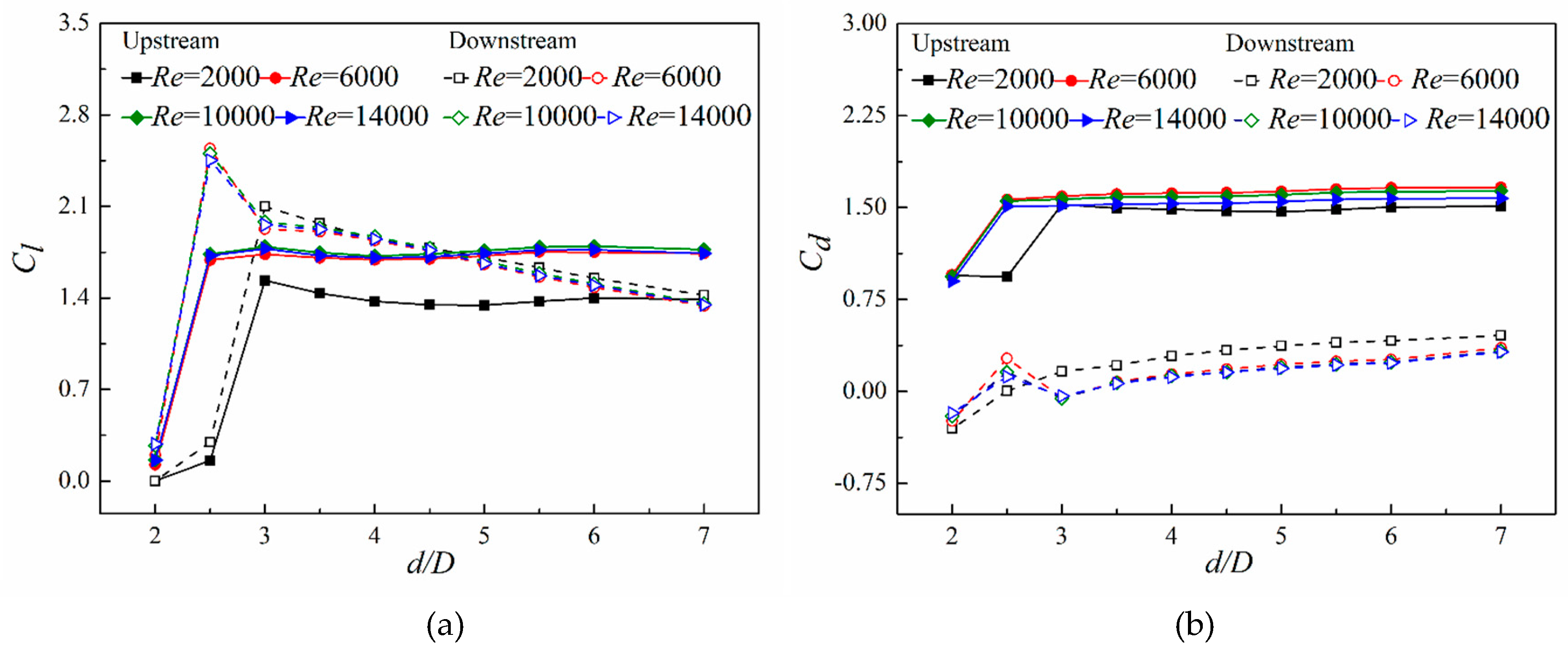
4.1.1. Lift and Drag Coefficient
4.1.2. Strouhal Number (St)
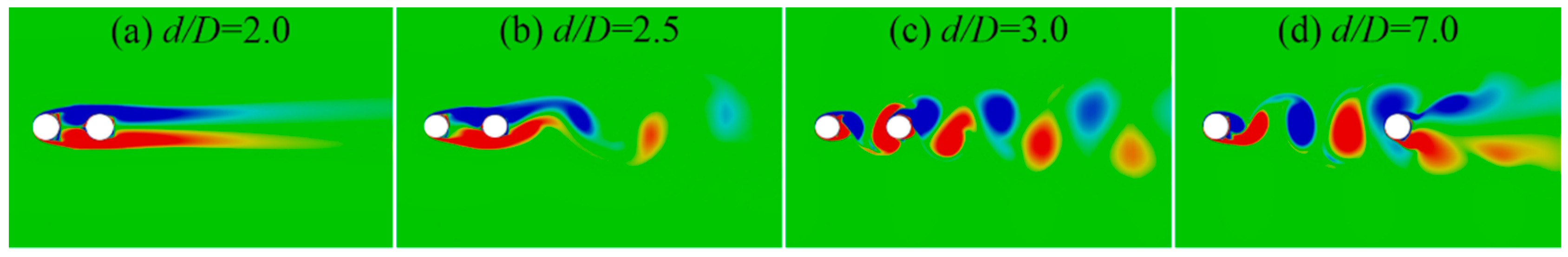
4.1.3. Wake Vortex Structure
4.2. Flow Induced Vibration of Two Staggered Cylinders
4.2.1. Vibration Characteristics Partition
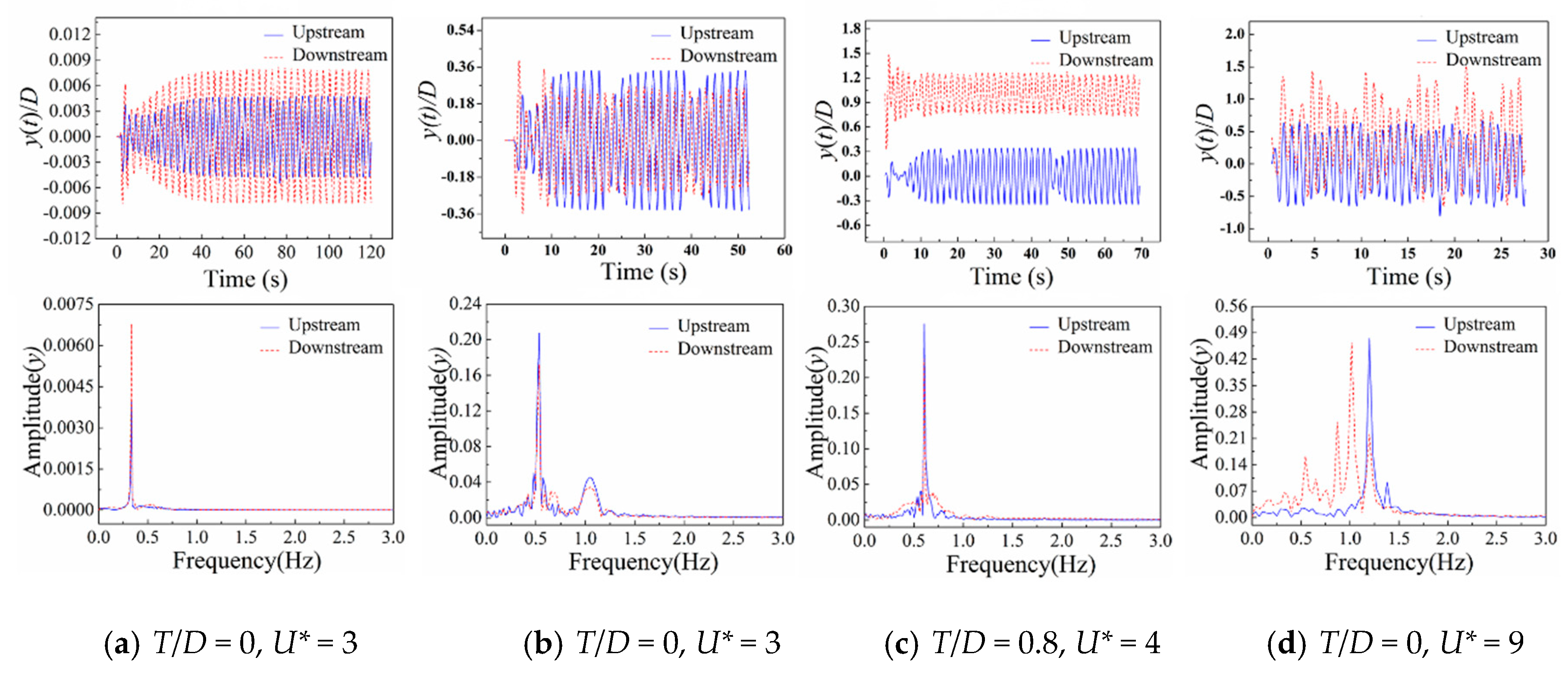
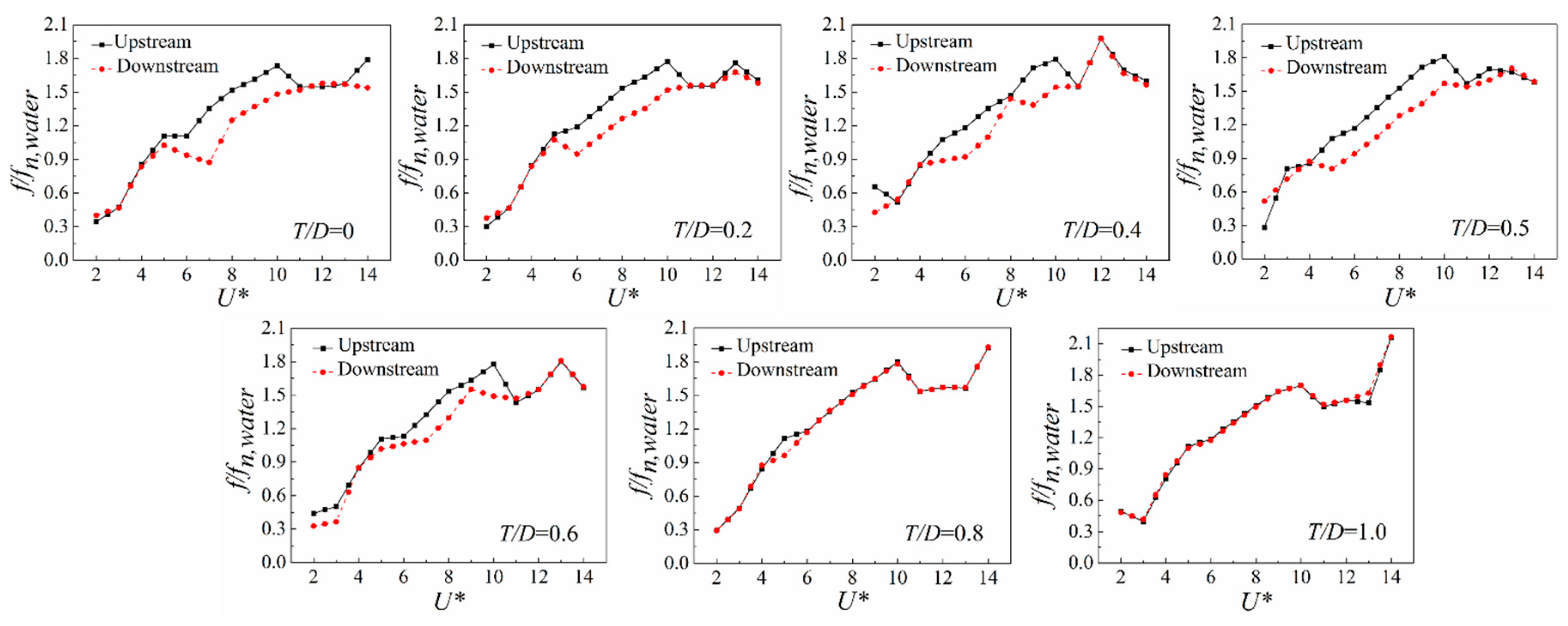
4.2.2. Amplitude and Frequency Responses
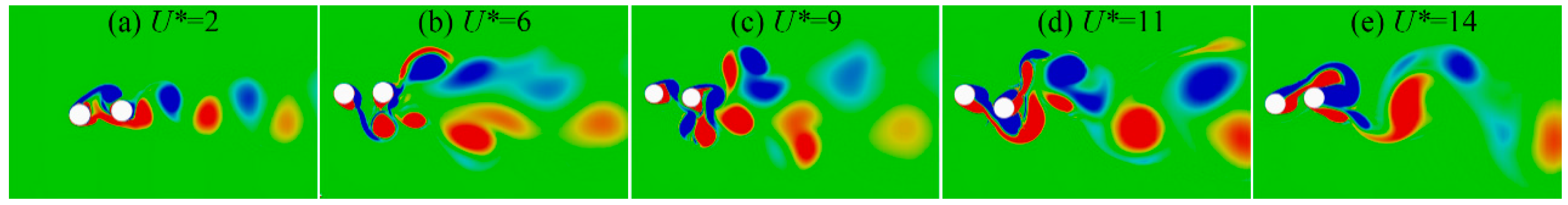
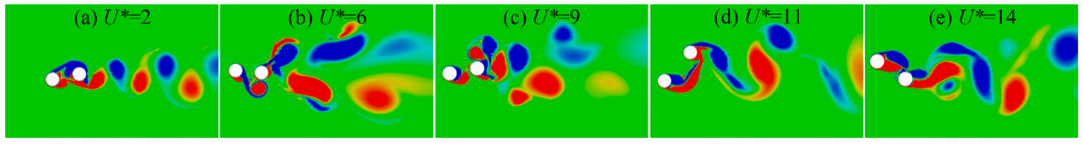
4.2.3. Wake Vortex Structure
5. Conclusion
- (1)
- For the two stationary cylinders, the spacing dc at which the gap flow can be observed is 3D when Re = 2000, dc = 2.5D at Re = 6000~14,000. When gap distance ratio d = dc, a gap flow is generated, and the lift–drag coefficient and the St of the cylinders increase sharply.
- (2)
- For the two staggered cylinders, the vibration modes include: Periodic vibration mode (small reduced velocity), double-periodic vibration mode (moderate reduced velocity and small staggered distance), multi-periodic vibration mode (moderate reduced velocity and large staggered distance) and quasi-periodic vibration mode (large reduced velocity).
- (3)
- When the staggered distance is changed, the amplitude of the upstream cylinder changes slightly, and the maximum amplitude can be obtained at U* = 6. The amplitude of the downstream cylinder varies significantly, and its maximum amplitude is obtained at T = 0.6D and U* = 12. The variation of vibration frequency of two cylinders is consistent. With the increase of staggered distance, the vibration frequencies of the two cylinders get closer.
- (4)
- At the same inflow velocity, the gap flow between the two cylinders is formed as the staggered distance increases. When T > 0.6D and U* < 8, gap flow becomes the main factor affecting the vibration of the two cylinders, which can be divided into the dominant region of gap flow. In other regions, the two cylinders can be approximated as the arrangement in series.
Author Contributions
Funding
Acknowledgments
Conflicts of Interest
References
- Xu, W.H.; Qin, W.Q.; Gao, X.F. Experimental Study on Streamwise Vortex-Induced Vibration of a Flexible, Slender Cylinder. Appl. Sci. Basel 2018, 8, 311. [Google Scholar] [CrossRef]
- Prasanth, T.K.; Mittal, S. Vortex-induced vibrations of a circular cylinder at low Reynolds numbers. J. Fluid Mech. 2008, 594, 463–491. [Google Scholar] [CrossRef]
- Chin, W.K.; Ong, Z.C.; Kong, K.K.; Khoo, S.; Huang, Y.H.; Chong, W. Enhancement of Energy Harvesting Performance by a Coupled Bluff Splitter Body and PVEH Plate through Vortex Induced Vibration near Resonance. Appl. Sci. Basel 2017, 7, 921. [Google Scholar] [CrossRef]
- Nguyen, T.; Koide, M.; Yamada, S.; Takahashi, T.; Shirakashi, M. Influence of mass and damping ratios on VIVs of a cylinder with a downstream counterpart in cruciform arrangement. J. Fluids Struct. 2012, 28, 40–55. [Google Scholar] [CrossRef]
- Williamson, C.H.K.; Govardhan, R. Vortex-induced vibrations. Annu. Rev. Fluid Mech. 2004, 36, 413–455. [Google Scholar] [CrossRef]
- Bearman, P.W. Circular cylinder wakes and vortex-induced vibrations. J. Fluids Struct. 2011, 27, 648–658. [Google Scholar] [CrossRef]
- Canpolat, C.; Sahin, B. Influence of single rectangular groove on the flow past a circular cylinder. Int. J. Heat Fluid Flow 2017, 64, 79–88. [Google Scholar] [CrossRef]
- Feng, L.H.; Ran, L.K. Wavelet multi-scale analysis of the circular cylinder wake under synthetic jets control. Int. J. Heat Fluid Flow 2018, 69, 73–82. [Google Scholar] [CrossRef]
- Lam, K.; Lin, Y.F.; Zou, L.; Liu, Y. Experimental study and large eddy simulation of turbulent flow around tube bundles composed of wavy and circular cylinders. Int. J. Heat Fluid Flow 2010, 31, 32–44. [Google Scholar] [CrossRef]
- Zhu, H.; Yao, J. Numerical evaluation of passive control of VIV by small control rods. Appl. Ocean Res. 2015, 51, 93–116. [Google Scholar] [CrossRef]
- Song, Z.; Duan, M.; Gu, J. Numerical investigation on the suppression of VIV for a circular cylinder by three small control rods. Appl. Ocean Res. 2017, 64, 169–183. [Google Scholar] [CrossRef]
- Wu, C.H.; Jaiman, R.K.; Lim, T.B.A.; Kang, C.W.; Ma, S. A new passive control technique for the suppression of vortex-induced motion in deep-draft semisubmersibles. Appl. Ocean Res. 2018, 80, 79–100. [Google Scholar] [CrossRef]
- Zhu, H.; Gao, Y.; Zhou, T. Flow-induced vibration of a locally rough cylinder with two symmetrical strips attached on its surface: Effect of the location and shape of strips. Appl. Ocean Res. 2018, 72, 122–140. [Google Scholar] [CrossRef]
- Chang, C.C.; Kumar, R.A.; Bernitsas, M.M. VIV and galloping of single circular cylinder with surface roughness at 3.0 × 10⁴ ≤ 1.2 × 10⁵. Ocean Eng. 2011, 38, 1713–1732. [Google Scholar] [CrossRef]
- Ding, L.; Bernitsas, M.M.; Kim, E.S. 2-D URANS vs. experiments of flow induced motions of two circular cylinders in tandem with passive turbulence control for 30,000 <Re <105,000. Ocean Eng. 2013, 72, 429–440. [Google Scholar]
- Ding, L.; Zhang, L.; Wu, C. Numerical Study on the Effect of Tandem Spacing on Flow-Induced Motions of Two Cylinders with Passive Turbulence Control. J. Offshore Mech. Arct. Eng. 2017, 139, 021801. [Google Scholar] [CrossRef]
- Ding, L.; Zhang, L.; Wu, C.; Mao, X.; Jiang, D. Flow induced motion and energy harvesting of bluff bodies with different cross sections. Energy Convers. Manag. 2015, 91, 416–426. [Google Scholar] [CrossRef]
- Ding, L.; Zhang, L.; Kim, E.S. URANS vs. experiments of flow induced motions of multiple circular cylinders with passive turbulence control. J. Fluids Struct. 2015, 54, 612–628. [Google Scholar] [CrossRef] [Green Version]
- Ding, L.; Zhang, L.; Bernitsas, M.M.; Chang, C.C. Numerical simulation and experimental validation for energy harvesting of single-cylinder VIVACE converter with passive turbulence control. Renew. Energy 2016, 85, 1246–1259. [Google Scholar] [CrossRef] [Green Version]
- Shan, X.B.; Deng, J.; Song, R.J.; Xie, T. A Piezoelectric Energy Harvester with Bending-Torsion Vibration in Low-Speed Water. Appl. Sci. Basel 2017, 7, 116. [Google Scholar] [CrossRef]
- Okajima, A.; Yasui, S.; Kiwata, T.; Kimura, S. Flow-induced streamwise oscillation of two circular cylinders in tandem arrangement. Int. J. Heat Fluid Flow 2007, 28, 552–560. [Google Scholar] [CrossRef]
- Zhou, Y.; So, R.M.C.; Liu, M.H.; Zhang, H.J. Complex turbulent wakes generated by two and three side-by-side cylinders. Int. J. Heat Fluid Flow 2000, 21, 125–133. [Google Scholar] [CrossRef]
- Harichandan, A.B.; Roy, A. Numerical investigation of low Reynolds number flow past two and three circular cylinders using unstructured grid CFR scheme. Int. J. Heat Fluid Flow 2010, 31, 154–171. [Google Scholar] [CrossRef]
- Chen, W.; Ji, C.; Williams, J.; Xu, D.; Yang, L.; Cui, Y. Vortex-induced vibrations of three tandem cylinders in laminar cross-flow: Vibration response and galloping mechanism. J. Fluids Struct. 2018, 78, 215–238. [Google Scholar] [CrossRef]
- Ding, L.; Zou, Q.F.; Zhang, L.; Wang, H. Research on Flow-Induced Vibration and Energy Harvesting of Three Circular Cylinders with Roughness Strips in Tandem. Energies 2018, 11, 2977. [Google Scholar] [CrossRef]
- Zhou, Y.; Alam, M.M. Wake of two interacting circular cylinders: A review. Int. J. Heat Fluid Flow 2016, 62, 510–537. [Google Scholar] [CrossRef]
- Mysa, R.C.; Kaboudian, A.; Jaiman, R.K. On the origin of wake-induced vibration in two tandem circular cylinders at low Reynolds number. J. Fluids Struct. 2016, 61, 76–98. [Google Scholar] [CrossRef]
- Tamimi, V.; Naeeni, S.T.O.; Zeinoddini, M. Flow induced vibrations of a sharp edge square cylinder in the wake of a circular cylinder. Appl. Ocean Res. 2017, 66, 117–130. [Google Scholar] [CrossRef]
- Pearcey, T.; Zhao, M.; Xiang, Y.; Liu, M. Vibration of two elastically mounted cylinders of different diameters in oscillatory flow. Appl. Ocean Res. 2017, 69, 173–190. [Google Scholar] [CrossRef]
- Griffith, M.D.; Jacono, D.L.; Sheridan, J.; Leontini, J.S. Flow-induced vibration of two cylinders in tandem and staggered arrangements. J. Fluid Mech. 2017, 833, 98–130. [Google Scholar] [CrossRef] [Green Version]
- Borazjani, I.; Sotiropoulos, F. Vortex-induced vibrations of two cylinders in tandem arrangement in the proximity–wake interference region. J. Fluid Mech. 2009, 621, 321–364. [Google Scholar] [CrossRef] [PubMed]
- Liu, B.; Jaiman, R.K. Interaction dynamics of gap flow with vortex-induced vibration in side-by-side cylinder arrangement. Phys. Fluids 2016, 28, 127103. [Google Scholar] [CrossRef]
- Liu, B.; Jaiman, R.K. Dynamics and stability of gap-flow interference in a vibrating side-by-side arrangement of two circular cylinders. J. Fluid Mech. 2018, 855, 804–838. [Google Scholar] [CrossRef]
- Spalart, P.R.; Allmaras, S.R. A One-Equation Turbulence Model for Aerodynamic Flows. Recherché Aerospatiale 1994, 1, 5–21. [Google Scholar]
- Zdravkovich, M.M. Flow around Circular Cylinders: Volume 1: Fundamentals; Oxford University Press: Oxford, UK, 2003. [Google Scholar]


| Parameters | Cylinder |
|---|---|
| Structural damping per unit length: C (N·s/m) | 1.36 |
| Spring stiffness per unit length: K (N/m) | 80.38 |
| System quality per unit length: mosc (kg/m) | 2.76 |
| Feature size: D (m) | 0.04 |
| Cylinder length: L (m) | 0.5 |
| Density of water at 15 °C: ρ (kg/m3) | 999.10 |
| Kinematic viscosity of water at 15 °C: ν (m2/s) | 1.14 × 10⁻⁶ |
| Grid number (Axial × Radial) | Drag coefficient (Cd) | Lift coefficient (Cl) | ||
|---|---|---|---|---|
| 1st | 2nd | 1st | 2nd | |
| Coarse (180 × 60) | 1.029 | −0.060 | 0.287 | 0.537 |
| Medium (240 × 70) | 1.039 | −0.065 | 0.299 | 0.561 |
| Fine (360 × 80) | 1.038 | −0.067 | 0.298 | 0.559 |
© 2019 by the authors. Licensee MDPI, Basel, Switzerland. This article is an open access article distributed under the terms and conditions of the Creative Commons Attribution (CC BY) license (http://creativecommons.org/licenses/by/4.0/).
Share and Cite
Yang, Z.-M.; Ding, L.; Ye, Q.-Y.; Yang, L.; Zhang, L. Effect of Gap Flow on the Characteristics of Flow-Around and Flow-Induced Vibration for Two Circular Cylinders with Roughness Strips. Appl. Sci. 2019, 9, 3587. https://doi.org/10.3390/app9173587
Yang Z-M, Ding L, Ye Q-Y, Yang L, Zhang L. Effect of Gap Flow on the Characteristics of Flow-Around and Flow-Induced Vibration for Two Circular Cylinders with Roughness Strips. Applied Sciences. 2019; 9(17):3587. https://doi.org/10.3390/app9173587
Chicago/Turabian StyleYang, Zuo-Mei, Lin Ding, Qian-Yun Ye, Lin Yang, and Li Zhang. 2019. "Effect of Gap Flow on the Characteristics of Flow-Around and Flow-Induced Vibration for Two Circular Cylinders with Roughness Strips" Applied Sciences 9, no. 17: 3587. https://doi.org/10.3390/app9173587