A New Concept Compliant Platform with Spatial Mobility and Remote Actuation


Department of Engineering, University of Roma Tre, via della Vasca Navale 79, 00146 Rome, Italy
Appl. Sci. 2019, 9(19), 3966; https://doi.org/10.3390/app9193966
Submission received: 27 June 2019
/
Revised: 10 September 2019
/
Accepted: 19 September 2019
/
Published: 21 September 2019
(This article belongs to the Special Issue Engineering for Surgery)
Abstract
:This paper presents a new tendon-driven platform with spatial mobility. The system can be obtained as a monolithic structure, and its motion is based on the concept of selective compliance. The latter contributes also to optimizing the use of the material by avoiding parasitic deformations. The presented platform makes use of lumped compliance with three different kinds of elastic joints. An analysis of the platform mobility based on finite element analysis is provided together with an assembly mode analysis of the equivalent pseudo-rigid body mechanism. Surgical operations in laparoscopic environments are the natural fields of applications for this device.
1. Introduction
A parallel architecture offers several advantages to the designers of spatial platform mechanisms. In fact, they rely on a multi-loop topology that is certainly convenient for the stage stiffness and accuracy, whereas their forward kinematic analysis becomes more complex.
The Stewart–Gough platform, a mechanism that can be considered to be a milestone of parallel manipulators, was presented in 1965 [1]. This six-DoF (degree of freedom) system can be controlled in any combination by six motors and has the advantage of no fixed axis relative to the ground. Classical issues for parallel manipulators have been extensively studied in the literature, such as structural kinematics [2], workspace [3], singularity [4], optimal design [5], structure synthesis [6], manipulability [7], control of redundantly-actuated [8], and remotely cable-driven parallel manipulators [9]. On the other hand, more recent subjects have still not been well investigated for parallel platforms, such as connectivity and redundancy [10], topology [11], and planarity [12].
Classical parallel platforms are composed of rigid links and ordinary kinematic pairs with a geometric closure configuration. However, they could be built as compliant mechanisms [13,14,15], which present a series of advantageous characteristics: they are not subject to backlash and do not need lubrication; they can be also built from a unique block of material; and finally, they have generally a neutral or balance configuration from which the deformed poses can be achieved. In fact, they can reach a given configuration thanks to external forces that can be applied with a high precision to deform the elastic structure, using also a redundant driving strategy. More recently, active compliance [16,17] has been added as a further possibility in design, acting both as a series or in a parallel configuration with passive compliance.
These features make compliant mechanisms very interesting for applications where lubrication is impossible or where extreme accuracy is needed. For these reasons, a group multi-DoF compliant stages has also been developed in literature [18].
Since 1990, stiffness and conditioning maps of the workspace of parallel manipulators have been established [19], in order to prevent special types of singularities, which result in a loss of controllability. A six-DoF force sensor was designed in 1991 [20] on the base of the Stewart–Gough platform. In this layout, the fixed and mobile platforms are coupled by six spring-loaded pistons, whereas the length variations are measured by means of six linear voltage differential transformers mounted along the pistons. The Stewart–Gough inverse and forward kinematic transformations are used to calculate the forces and torques that are applied to the mobile platform. A three DoF translational compliant parallel platform was presented in 2005 [21] for nanomanipulation. Workspace, dexterity, and isotropic configurations were studied by using the pseudo rigid-body model (PRBM). A six-PSS (prismatic-spherical-spherical) nanopositioner compliant mechanism was designed [22] to be actuated by means of six multilayered piezoelectric actuators. The system is composed of one fixed plate, three two-PSS compliant mechanisms, and one end effector. The PRBM is also used in this investigation to study its kinematic analysis. A three DoF spatial translational accurate positioning compliant platform with flexible hinges and with piezoelectric actuators has been designed [23] to achieve high stiffness, a high speed of dynamic response, high kinematic accuracy, and high resolution. A six-DoF compliant parallel micro-scale manipulator with piezo-driven actuators and integrated force sensor has been designed [24] to provide real-time force information for feedback control. Kinematic and static analysis were investigated to achieve high positioning accuracy, compactness, and smooth and continuous displacements. A method for the optimal design and performance characterization of micromanipulators has been also applied to six-DOF parallel micromanipulators [25]. A three-DoF compliant platform has been studied [26] to make it able to move in three-dimensional space. The system was composed of compliant joints, actuators, and a central moving platform. The actuators consisted of three binary links, while the moving platform was an equilateral plate. The free end of each actuator and the central platform were connected by springs in such a way that the motion of the actuators was transmitted to the moving platform. Considering the applications at the micro scale and using the technology on which micro electro-mechanical systems (MEMS) are based, a compliant three-DoF plane parallel platform has been proposed [27] together with its kinetostatic optimization.
The “da Vinci” © surgical robot (by Intuitive Surgical, Inc., Sunnyvale, California, USA) is a widely-used system designed to facilitate surgical operations with a minimally-invasive approach. This robot makes use of multi-DoF end terminals as a resource to cope with different tasks, working in cooperation with robotic wrists or steerable instruments, and their characteristics have been extensively improved and refined throughout the years. For example, a 2 mm-diameter instrument equipped with a three-DoF wrist has been investigated and tested [28] for the robotic “da Vinci” platform. Moreover, new systems for measuring the end effector gripping force have also been developed by means of a torque transfer system [29]. Finally, deflection and force feedback from the “da Vinci” end effector have been provided by new types of strain gauges [30].
However, in most of the above-mentioned systems for remote manipulations that are widely adopted for minimally-invasive surgery, the wrists and end effector consist of mechanisms that have ordinary kinematic pairs, which are subject to backlash problems, and a serial kinematic structure, which is usually less robust than a parallel structure. The present paper presents a new six-DoF platform for remote manipulation that consists pf a mechanism with selective compliance (compliant mechanism) and has also a parallel structure. The device could be either part of “da Vinci” or independently driven by another positioning system. Originally, the system was conceived to work under a laparoscopic environment, and it is expected to improve its success in surgery, such as in laparoscopic sleeve gastrectomy (LSG) with cruroplasty [31], in surgical treatment of gastrointestinal stromal tumors of the duodenum [32], in colovesical fistula surgery with a minimally-invasive approach [33], in endoluminal loco-regional resection by transanal endoscopic microsurgery (TEM) [34,35,36], and also in low rectal anterior resection (LAR) [37].
2. Description of the New Concept Platform
In several applications, the position of a mobile platform in space has to be controlled by using remote means, such as cables. Usually, the conventional mechanisms that are able to implement such a feature are rather complicated because the platform has six degrees of freedom (DoF), and moreover, they are subject to backlash and parasitic deformations. This problem is quite general, but in this paper, a specific implementation suitable for surgical applications will be presented.
A new tendon-driven compliant mechanism is herein proposed, as a possible solution to the above-mentioned problem. The full mobility of the platform in space and, in particular, its raising motion is possible because of a new elastic joint, which combines the action of an elastic curved beam and of a portion of the conjugate surfaces. The invention consists basically of a wire-operated selective compliance mobile platform like the one represented in Figure 1. The mechanism base (k) is intended to be mounted on the end of a flexible tubular duct for endoscopic, surgical, therapeutic, or diagnostic uses.
The platform (a) is designed for supporting surgical means, normally used during endoluminal operations, such as vision systems, forceps, scissors, cannulae, electrotomes, and so on. However, the system could be used for precision applications or in adverse environments, e.g., for operations in the aerospace environment. The base (k) and the platform (a) are connected through a plurality of legs, which provide mobility in space to the mobile surface (a), and are operated by actuating wires (i) and (f), running inside the tubular duct, to control and operate the platform remotely.
Since the mechanical structure of the mechanism is based on selective compliance and, particularly, on lumped compliance, there is a neutral configuration that is assumed when no external force is acting on the structure.
2.1. Deduction of the Pseudo-Rigid Body Equivalent Mechanism
A compliant mechanism can be generally modeled as its equivalent so-called pseudo-rigid body mechanism (PRBM). The PRBM is a mechanism with only ordinary kinematic pairs, which presents approximately the same motion as the original compliant mechanism in the neighborhood of the neutral configuration. For this purpose, each elastic joint is replaced by an ordinary kinematic pair, which can offer mobility that is compatible with the selective compliance characteristics of that elastic joint. Figure 2 shows the original compliant mechanism (Figure 2a) and its corresponding spatial PRBM (Figure 2b).
With reference to Figure 1 and Figure 2, the elastic joints can be distinguished according to the following characteristics.
- A Type (e) elastic joint is delimited by a toroidal surface obtained by revolving a circular arc around a vertical axis . As a consequence, the neck cross-sectional area is normal to and is positioned in correspondence to the symmetry middle plane of the joint surface. The relative motion between the two connected pseudo-rigid parts has at least two degrees of freedom (DoF), namely those due to the bending along two orthogonal planes passing through . Furthermore, one more DoF could be added depending on whether the neck section allows the two opposite end sections to rotate significantly, one with respect to the other, about . For Type (e) joints, the choice of the diameter of the neck section is decisive for assuming whether the amount of torsional rotation might play a significant role. If so, Type (e) can be replaced by a three-DoF spherical S joint, otherwise a two DoF (Hooke’s) universal U will be used. In the latter case, the flexure works approximately as a Cardan joint whose center is placed at the center of elastic weights of the elastic joint itself.
- A Type (c) elastic joint is also delimited by a portion of a toroidal surface obtained by the rotation of a circular arc around an axis of revolution . For this type of joint, the rotations about are considered to be always non-negligible. In fact, they are provided with an even more reduced middle cross-section that gives rise to possible torsion rotations about . Therefore, the joints (c) substantially have the function of spherical elastic joints, the equivalent center of the spherical kinematic pair being placed at the center of elastic weights of the joint itself. For this reasons, Type (c) joints will be replaced by spherical joints S.
- Type (h) elastic joints belong to the class of the conjugate surface flexure hinge (CSFH). This kind of flexure has been patented (see Section 7) and extensively studied for several aspects: their theoretical behavior [38,39], design [40,41], dynamic simulation [42], fabrication [43,44,45], and applications [46,47,48,49,50,51]. Type (h) CSFH hinges selectively provide rotations around the CSFH axis with a very good accuracy, because of the presence of a portion of conjugate surfaces. Therefore, they are replaced by classical revolute joints R.
- Type (f) cables are the three moving elements for Type (d) upper links out of a total of six cables that are used to operate the six-DoF platform. For example, a simultaneous pull command on the three Type (f) cables will move the platform downward. The cables may be arranged in such a way so as to be aligned in the three directions , , and , as illustrated in Figure 2a.
- Type (i) cables are the moving elements for Type (g) links. These three cables provide motion for the three CSFH hinges, and so, they regulate the orientation of Type (g) links. For example, a cable pull will induce a rotation that tends to raise the link upward.
Three linear actuators are added to the system and positioned as in Figure 2b in order to replace the three actuated cables directed along the , , and directions. The three linear actuators are identified in the figure as the ones that are incident to the triple spherical joint positioned at Point B. This replacement is justified by the fact that the three cables are directed along lines that pass through the center Bof the triple spherical joint . This point is positioned in the middle of the fixed platform, in correspondence to a level that does not interfere with the CSFH hinges.
Finally, it is worth noting that the identification of a PRBM that adequately corresponds to the proposed compliant structure represents the first necessary step to further analyze the new systems, such as workspace and kinematic analysis, kinematic synthesis, and kinetostatic behavior.
2.2. Topological Analysis
Considering an equivalent mechanism PRBM with rigid bodies and classical U, S, and R pairs, three legs guarantee six degrees of freedom to the platform. In fact, the PRBM presents rigid links and kinematic pairs. In case Type (e) joints are replaced by U joints, the structure will be composed of three Type (h) revolute joints R with degree of constraint in space, three Type (e) U joints with , and six S joints with . Therefore, according to the general topological Grubler’s formula, the PRBM has:
overall degrees of freedom (DoF), where is the mobility number for general spatial motion.
As mentioned above, torsion cannot always be excluded on U elastic Type (e) joints, depending on the minimum diameter of the normal cross-section, which would make them practically equivalent to S joints. In this case, Grubler’s formula would yield DoFs for the platform, but it must be remarked that three of such DoFs would be uniquely dedicated to providing idle rotations to the upper Type (d) links. In this case, any Link (d) would be connected to the remaining parts of the structure by means of two S type pairs, and so, rotations about an axis passing through the centers of the two spherical joints would be possible. These rotations are naturally counterbalanced by internal elastic reactions that would drive the system back toward the minimum of the potential elastic energy. Alternatively, they could make it easier to achieve an optimal attitude of Type (f) cables that pull down Type (d) links. For these reasons, a different manipulator could be obtained, as an alternative, where Type (e) links are replaced by Type (c) links, with no problems for mobility.
According to the result obtained by using Equation (1) and considering that each leg is supposed to be controlled by two cables, a three-legged platform will be the one that has a number of independent actuators that is equal to the number of DoF and therefore will be considered as an optimal choice for the compliant structure. In fact, according to the principle of selective compliance, any elastic element where compliance is concentrated presents a peculiar geometry that is intended for a specific deformation, for example a prescribed flexion or torsion axis, and all the deformations different from the prescribed ones are considered to be as parasitic deformations, because they do not contribute to the desired motion, but only increase the stress level in the elastic material. For this reason, a satisfying geometry of a compliant mechanism is the one that minimizes the parasitic deformations.
2.3. Direct Position Analysis
Thanks to the construction of the PRBM depicted in Figure 2b, it is possible to identify some fundamental characteristics of the platform, as they have been introduced in the literature. For example, it is clear that this platform is not a fully-parallel platform, because two DoF are needed for each leg. With reference to Figure 3a, the ith leg (with ) will be composed of the pseudo rigid links and , which respectively correspond to Type (g) and Type (d) links of the original compliant structure.
For the generic ith leg, one DoF is firstly required to define the angular position of Type (g) link . An angle can be introduced to measure the rotation of () with respect to its position in the undeformed configuration of the CSFH joint. Since the latter corresponds to a revolute joint with a known rotation axis, the angle uniquely identifies the position of the center of the spherical pair. Secondly, another DoF is needed to assess the position of the upper Type (d) link of the ith leg. Indeed, an assigned pull command on the Type (f) cable has the effect of bringing points and B closer to each other. This effect could be similarly obtained by introducing in the PRBM a virtual linear actuator being active along the line . Any contraction of the linear actuator corresponds to a pull command of the (f) rope, while an extension of the linear actuator would represent a reduction of the cable tension. Since mobility is granted by the elasticity of the structure, its overall configuration will depend on the whole set of tensions that are assigned to the six cables. Furthermore, it is worth noticing that positive tensions (push) are not considered here, and therefore, the maximum elongation of the three virtual linear actuators will depend on the whole balance between the tensions that are applied to the cables and the structural elasticity. For the linear actuator , the pulled distance can be introduced as the shortening of the original length with respect to the distance between points B and in the undeformed structure configuration.
Once the input parameters and have been assigned, the chain behaves as a rigid structure, which may rotate about the axis passing through points and B (see Figure 3b). Therefore, point describes a circle laying on a plane that is orthogonal to and whose center is on line . Since can be regarded as a rigid link, point is also forced to lay on a circle that lays on a plane parallel to . The center of is on the line .
Considering the three loci (with ) of the possible positions of the points , it is clear that three points of the upper platform, coincident with , , and , will belong to the three circles , , and , respectively. However, exactly the same constraint could be imposed by introducing a virtual link , represented in Figure 3b, that rotates about the axis. Therefore, three new links , with , can be used to get rid of the three whole chains made of links , , and the linear actuators . After this substitution, a new three-legged structure is obtained, as depicted in Figure 4.
The new mechanism will have a null DoF because the whole set of input positions has already been assigned. In fact, after assigning a value to the three angles and to the three displacements , the axes , the lengths , and the positions of points can be uniquely identified. The resulting structure consists of a mobile platform that is connected to the base via three links only arranged in a parallel configuration, each one having one revolute R and one spherical S joint at its ends incident to the base and the platform, respectively. This structure has received the attention of several eminent scholars in the field and has been extensively studied [52,53,54]. From the geometric and kinematic point of view, the study of the possible assembly modes of this zero-DoF structure gives the same solution as for problem of finding the assembly modes of a six-DoF, so called 6-3-type fully-parallel mechanism, belonging to the class of Stewart platform mechanisms, once six elongation values are assigned to the six linear actuators along its legs.
Innocenti and Parenti Castelli solved the direct position analysis in 1990 [55] and found results that were coherent with Hunt’s works [2]. According to this method (see also [56]), three closed-loop vector equations:
can be written, where , , and are the edges of the upper platform.
For the sake of the present investigation , , and have constant modules because of the symmetry of the upper platform. Therefore, given the constant length l of the upper platform edges, Equation (2) can be rewritten as:
from which three scalar conditions are obtained where the three unknown are the rotation angles (with ) of the virtual bars around the axes .
It is now essential to remind that once the three rotations of the CSFHs and the three displacements of the Type (f) cables have been assigned, the zero-DoF structure illustrated in Figure 4 is completely configured because the positions of the points , , and can be easily calculated. Therefore, the solutions of the problem expressed by the set of Equation (3) are also the solution of the assembly configuration for the PRBM mechanism depicted in Figure 3a.
The system (3) consists of three second-order algebraic equations in three unknowns (with ), where any equation contains two unknown variables only. Therefore, the solutions can be achieved by firstly eliminating one variable from two equations where appears, so obtaining one equation in the other two variables, and then, by eliminating one of the other two variables, say , from the remaining two equations. The result is a 16th-order polynomial equation in the remaining variable , with 16 real and complex solutions for . Since for every solution , unique values of and exist, a unique location of the upper platform is identified for each solution . These solutions correspond to the possible assembly configurations of the structure represented in Figure 4 and, as a consequence, of the PRBM depicted in Figure 3a, provided that the six inputs and have been assigned. However, for the sake of the present investigation, the only interesting solution will be the one compatible with rotations and displacements starting from the initial undeformed configuration represented in Figure 2a. This shows that the numerical approaches could be used more conveniently than the purely analytical ones, because they could converge to the actual configuration by using the undeformed pose as the starting guess. In the next section, finite element analysis (FEA) is applied to the compliant platform illustrated in Figure 2a, by assigning three different sets of input displacements.
3. Numerical Simulation of the Platform Pose
The peculiar geometry illustrated in Figure 1 is the result of a preliminary study that led to the definition of the patented structure. Three equal legs were positioned in a parallel configuration, each leg being actuated by two cables, and so, the whole structure was a tendon-driven mechanism. The geometry of each leg was chosen in such a way that the lower and upper cables induced a raising and lowering motion, respectively. The attachment points were also selected in order not to induce cable jamming. Further optimization of the attachment points and of the angles of the pseudo-rigid links will be the object of future investigations. Considering the nomenclature introduced in Figure 1, any moving cable (i) acts on a CSFH turning pair, relevantly operates the bending of the CSFH Type (h) flexure, and actually drives the rotations of Type (g) links. Cables (f) will have the effect of pulling the platform down because they are attached to the upper links. More in general, a configuration of the platform (a) will be defined by the whole set of forces applied to all the wires, since it depends on the interaction between the applied forces and the elasticity of joints.
Finite element analysis is a convenient way to assess the deformation of the whole structure for assigned values of the cable displacements. More specifically, FEA provided evidence that the adoption of the proposed platform can be a promising approach to find an efficient way for remote handling in several contexts.
Finite Element Analysis
Finite element analyses were conducted to evaluate the static behavior of the parallel platform. Three cases were considered depending on three different sets of input parameters and using Pa as the material Young’s modulus.
Three cases will be studied:
- I
- pull on Type (f) cables and null tension on Type (i) cables;
- II
- pull on Type (i) cables and null tension on Type (f) cables;
- III
- asymmetric pull: pull on one Type (f) cable and pull on two Type (i) cables;
The fixed reference frame () and the unit vectors () attached to the mobile platform were positioned as in Figure 5a. This figure also shows the input displacement . Rotations , , and were assumed to be about , , and , respectively.
In the first case, a displacement was imposed on each one of the Type (f) cables, equal to mm, and null tensions on Type (i) cables, giving rise to null rotation angles of the three CSFH hinges. The deformed configuration is reported in Figure 5b, showing a platform displacement along the z-axis in the negative direction. No other significant displacements or rotations were registered.
The second case corresponded to with mm. The deformed configuration is reported in Figure 6a, showing a platform displacement along the z-axis in the positive direction. Analogous to the previous case, no other significant displacements or rotations were registered.
The third case corresponded to a general actuation scheme with , mm, mm. The deformed configuration is reported in Figure 6b, showing a platform displacement with components along the and y-axes and rotations about the x- and z-axes.
The input parameters, the platform displacement, and the rotations are reported in Table 1 for the three analyzed cases.
4. Applications
Originally, the main activities for the invention herein presented were intended to be operated in the laparoscopic environment. Figure 7 shows a possible end-effector that could be mounted on the platform. With reference to the labels used in Figure 7, the endoluminal catheter (a) carries the base platform (b), which supports three Type (c) legs on which the mobile platform (d) is mounted. The mobile platform surface holds the surgical means (f) that can vary according to the type of required operation. Other miniaturized instruments can be mounted on the controlled platform, such as vision means (e) that allow the surgeon to observe the corporal cavity wherein the device is inserted. Moreover, a communication duct (g) was designed, allowing the surgeon to access the region to be operated. For this reason, the mobile and base platforms were also provided with an opening that connects the duct (g) with the tubular duct (a). With reference to Figure 7, it should be also noted that the surgical device was comprised of a shaped surface (f) that made it easier to act as a guiding element inside the cavity during the use of the device.
5. Discussion
The aim of this paper was to present a new concept high accuracy platform with spatial mobility, remotely actuated, and equipped with selective compliance joints. The system can be built on a unique material block or with a reduced number of components, which reduces the costs and time of production. It can be also built by means of 3D printing.
The platform was mounted on three arms, and it was remotely controlled by six wires. The system included a mobile plane and a connection base fixed to an endoscopic instrument. The instruments was accurate and maneuverable with continuous motion granted by the interaction between the cable tensions and the elastic energy stored in the elastic media. Based on selective compliance, the principle of design gave rise to optimal configurations where parasitic motions, friction, and wear were minimized. No lubrication was needed.
The invention is expected to drive surgical operations in laparoscopic, endogastric, or endarterial environments, but other applications are not excluded, such as in aerospace, automotive, appliances, and microelectronics. However, it is worth noting that the platform fabrication and its actual implementation for real operations deserve further refinements, and therefore, they will be treated in future contributions. Among the important subjects that still represent open problems, the following will be briefly addressed.
The first problem is the selection of an optimal material for the elastic parallel mechanism. This choice will depend on the overall size of the device and on the consequent preferred method of machining. In any case, some desired characteristics of a material that could be conveniently employed to build a compliant mechanism block were proposed in [57], among which are good performances at variable temperatures, biocompatibility, low susceptibility to creep, resistance to wear and fatigue, and the predictability of such properties. However, the most important characteristic is a high value of the ratio of the yield strength to Young’s modulus. According to Table 2.1. presented in [57], there are several materials that have an acceptable ratio, among which are nylon, e-glass, Kevlar, and polyethylene.
The actual fabrication of the device will depend both on size and material. Unfortunately, the geometry is rather complicated, and so, many of the classical machining operations would be problematic.
The identification of a proper PRBM, as proposed in the present contribution, could be helpful to complete typical tasks in robotics, such as the study of the critical configurations. Furthermore, the PRBM will be useful to optimize the platform and the legs’ geometry, in order to suit the required workspace, mobility, and mechanical advantage.
Finally, an efficient control algorithm would be required for each specific application.
6. Conclusions
A spatial, selective compliance, tendon-driven, and parallel platform was described and analyzed. This system was quite different from the compliant mechanisms previously presented either in the literature or the national patent institutions until today. Its mechanical structure was studied by identifying the equivalent pseudo-rigid body mechanism. The platform was also simulated with finite element analysis (FEA) by assigning different sets of cable tensions and obtaining results that matched well with the expected behavior. It is hoped that this article will offer new perspectives for general tasks of spatial body guidance and particularly in laparoscopic surgery.
7. Patents
The following patents describe the new concept platform and the related claims.
- N.P. Belfiore, M. Scaccia, F. Ianniello, M. Presta, L. Perfetti, Selective Compliance Wire Actuated Mobile Platform, particularly for Endoscopy Surgical Devices, Patent N0.2 US 8,845,520 B2, 30 September 2014.
- N.P. Belfiore, M. Scaccia, F. Ianniello, M. Presta, L. Perfetti, Selective Compliance Wire Actuated Mobile Platform, particularly for Endoscopy Surgical Devices, World Intellectual Property Organization, WO 2009/034552 A2, Int. Appl. No. PCT/IB2008/053698, Publ. Date 19 March 2009.
- N.P. Belfiore, M. Scaccia, F. Ianniello, M. Presta, Selective Compliance Hinge, US 8,191,204 B2, 5 June 2012.
- N.P. Belfiore, M. Scaccia, F. Ianniello, M. Presta, Selective Compliance Hinge, World Intellectual Property Organization, WO 2009/034551 A1, Int. Appl. No. PCT/IB2008/053697, Publ. Date 19 March 2009.
Funding
This research received no external funding.
Acknowledgments
The whole staff of the “Research and Technology Transfer Area” of the University of Rome la Sapienza is gratefully acknowledged. Particular thanks go to the Manager of the “Research and Technology Transfer Area” Antonella Cammisa, the Office Manager of the “Enhancement and Technology Transfer Office” Daniele Riccioni, and the Office Manager of the “Grant Office” Alessandra Intraversato, for their counseling and support during my long stay at Sapienza University. I am also grateful to several people from my new University of Roma Tre (my list would be too long to mention all of them) for supporting and encouraging me since my arrival in October 2017.
Conflicts of Interest
The author declares no conflict of interest.
Abbreviations
The following abbreviations are used in this manuscript:
| CSFH | Conjugate surface flexure hinge |
| DoF | Degrees of freedom |
| MEMS | Micro electro-mechanical systems |
References
- Stewart, D. A Platform with Six Degrees of Freedom. Proc. Inst. Mech. Eng. 1965, 180, 371–386. [Google Scholar] [CrossRef]
- Hunt, K.H. Structural Kinematics of in-parallel-actuated Robot-Arms. J. Mech. Transm. Autom. Des. 1983, 105, 705–712. [Google Scholar] [CrossRef]
- Gosselin, C. Determination of the workspace of 6-DOF parallel manipulators. J. Mech. Transm. Autom. Des. 1990, 112, 331–336. [Google Scholar] [CrossRef]
- Innocenti, C.; Parenti-Castelli, V. Singularity-free evolution from one configuration to another in serial and fully-parallel manipulators. J. Mech. Des. Trans. ASME 1998, 120, 73–79. [Google Scholar] [CrossRef]
- Parenti-Castelli, V.; Di Gregorio, R.; Bubani, F. Workspace and optimal design of a pure translation parallel manipulator. Meccanica 2000, 35, 203–214. [Google Scholar] [CrossRef]
- Fang, Y.; Tsai, L.W. Structure synthesis of a class of 4-DoF and 5-DoF parallel manipulators with identical limb structures. Int. J. Robot. Res. 2002, 21, 799–810. [Google Scholar] [CrossRef]
- Merlet, J.P. Jacobian, manipulability, condition number, and accuracy of parallel robots. J. Mech. Des. Trans. ASME 2006, 128, 199–206. [Google Scholar] [CrossRef]
- Cheng, H.; Yiu, Y.K.; Li, Z. Dynamics and Control of Redundantly Actuated Parallel Manipulators. IEEE/ASME Trans. Mechatron. 2003, 8, 483–491. [Google Scholar] [CrossRef]
- Tang, X. An overview of the development for cable-driven parallel manipulator. Adv. Mech. Eng. 2014, 2014. [Google Scholar] [CrossRef]
- Belfiore, N.P.; Di Benedetto, A. Connectivity and redundancy in spatial robots. Int. J. Robot. Res. 2000, 19, 1245–1261. [Google Scholar] [CrossRef]
- Belfiore, N.P. Distributed Databases for the development of Mechanisms Topology. Mech. Mach. Theory 2000, 35, 1727–1744. [Google Scholar] [CrossRef]
- Belfiore, N.P. Brief note on the concept of planarity for kinematic chains. Mech. Mach. Theory 2000, 35, 1745–1750. [Google Scholar] [CrossRef]
- Howell, L.L.; Magleby, S.P.; Olsen, B.M. Handbook of Compliant Mechanisms; John Wiley and Sons: The Atrium Southern Gate, Terminus Road, Chichester, West Sussex, UK, 2013. [Google Scholar]
- Howell, L.L.; Midha, A. Parametric deflection approximations for end-loaded, large-deflection beams in compliant mechanisms. J. Mech. Des. Trans. ASME 1995, 117, 156–165. [Google Scholar] [CrossRef]
- Howell, L.L.; Midha, A. A method for the design of compliant mechanisms with small-length flexural pivots. J. Mech. Des. Trans. ASME 1994, 116, 280–290. [Google Scholar] [CrossRef]
- Verotti, M.; Masarati, P.; Morandini, M.; Belfiore, N.P. Isotropic compliance in the Special Euclidean Group SE(3). Mech. Mach. Theory 2016, 98, 263–281. [Google Scholar] [CrossRef]
- Verotti, M.; Belfiore, N.P. Isotropic compliance in E(3): Feasibility and workspace mapping. J. Mech. Robot. 2016, 8. [Google Scholar] [CrossRef]
- Dunning, A.; Tolou, N.; Herder, J. Review Article: Inventory of platforms towards the design of a statically balanced six degrees of freedom compliant precision stage. Mech. Sci. 2011, 2, 157–168. [Google Scholar] [CrossRef] [Green Version]
- Gosselin, C. Stiffness Mapping for Parallel Manipulators. IEEE Trans. Robot. Autom. 1990, 6, 377–382. [Google Scholar] [CrossRef]
- Nguyen, C.C.; Antrazi, S.S.; Zhou, Z.L. Analysis and implementation of a 6 DOF Stewart platform-based force sensor for passive compliant robotic assembly. In Proceedings of the IEEE SOUTHEASTCON, Williamsburg, VA, USA, 7–10 April 1991; Volume 2, pp. 880–884. [Google Scholar]
- Li, Y.; Xu, Q. Design and analysis of a new 3-DOF compliant parallel positioning platform for nanomanipulation. In Proceedings of the 5th IEEE Conference on Nanotechnology, Nagoya, Japan, 15 July 2005; Volume 2, pp. 133–136. [Google Scholar]
- Wu, T.L.; Chen, J.H.; Chang, S.H. A six-dof prismatic-spherical-spherical parallel compliant nanopositioner. IEEE Trans. Ultrason. Ferroelectr. Freq. Control 2008, 55, 2544–2551. [Google Scholar]
- Chen, Q.; Huang, Y.; Zhu, D.; Zhou, M. The design and finite element analysis of a compliant 3-DOF spatial translational ultra-precise positioning platform. In Proceedings of the IEEE International Conference on Intelligent Computing and Intelligent Systems, Xiamen, China, 29–31 October 2010; Volume 3, pp. 122–126. [Google Scholar]
- Liang, Q.; Zhang, D.; Chi, Z.; Song, Q.; Ge, Y.; Ge, Y. Six-DOF micro-manipulator based on compliant parallel mechanism with integrated force sensor. Robot. Comput.-Integr. Manuf. 2011, 27, 124–134. [Google Scholar] [CrossRef]
- Liu, X.J.; Wang, J.; Gao, F.; Wang, L.P. On the design of 6-DOF parallel micro-motion manipulators. In Proceedings of the IEEE International Conference on Intelligent Robots and Systems, Maui, HI, USA, 29 October–3 November 2001; Volume 1, pp. 343–348. [Google Scholar]
- Correa, J.C.; Crane, C. Kinematic analysis of a three-degree of freedom compliant platform. J. Mech. Des. Trans. ASME 2013, 135. [Google Scholar] [CrossRef]
- Belfiore, N.P.; Emamimeibodi, M.; Verotti, M.; Crescenzi, R.; Balucani, M.; Nenzi, P. Kinetostatic optimization of a MEMS-based compliant 3 DOF plane parallel platform. In Proceedings of the 9th International Conference on Computational Cybernetics, Tihany, Hungary, 8–10 July 2013; pp. 261–266. [Google Scholar]
- Francis, P.; Eastwood, K.W.; Bodani, V.; Looi, T.; Drake, J. Design, Modelling and Teleoperation of a 2 mm Diameter Compliant Instrument for the da Vinci Platform. Ann. Biomed. Eng. 2018, 46, 1437–1449. [Google Scholar] [CrossRef] [PubMed]
- Lee, C.; Park, Y.H.; Yoon, C.; Noh, S.; Lee, C.; Kim, Y.; Kim, H.C.; Kim, H.H.; Kim, S. A grip force model for the da Vinci end-effector to predict a compensation force. Med Biol. Eng. Comput. 2015, 53, 253–261. [Google Scholar] [CrossRef] [PubMed]
- Pena, R.; Smith, M.J.; Ontiveros, N.P.; Hammond, F.L.; Wood, R.J. Printing Strain Gauges on Intuitive Surgical da Vinci Robot End Effectors. In Proceedings of the IEEE International Conference on Intelligent Robots and Systems, Madrid, Spain, 1–5 October 2018; Institute of Electrical and Electronics Engineers Inc.: Piscatawa, NJ, USA, 2018; pp. 806–812. [Google Scholar]
- Balla, A.; Quaresima, S.; Ursi, P.; Seitaj, A.; Palmieri, L.; Badiali, D.; Paganini, A.M. Hiatoplasty with crura buttressing versus hiatoplasty alone during laparoscopic sleeve gastrectomy. Gastroenterol. Res. Pract. 2017, 2017. [Google Scholar] [CrossRef] [PubMed]
- Popivanov, G.; Tabakov, M.; Mantese, G.; Cirocchi, R.; Piccinini, I.; D’Andrea, V.; Covarelli, P.; Boselli, C.; Barberini, F.; Tabola, R.; et al. Surgical treatment of gastrointestinal stromal tumors of the duodenum: A literature review. Transl. Gastroenterol. Hepatol. 2018, 3, 71. [Google Scholar] [CrossRef]
- Cochetti, G.; Del Zingaro, M.; Boni, A.; Cocca, D.; Panciarola, M.; Tiezzi, A.; Gaudio, G.; Balzarini, F.; Ursi, P.; Mearini, E. Colovesical fistula: Review on conservative management, surgical techniques and minimally invasive approaches. Giornale Chir. 2018, 39, 195–207. [Google Scholar]
- Quaresima, S.; Balla, A.; Dambrosio, G.; Bruzzone, P.; Ursi, P.; Lezoche, E.; Paganini, A.M. Endoluminal loco-regional resection by TEM after R1 endoscopic removal or recurrence of rectal tumors. Minim. Invasive Ther. Allied Technol. 2016, 25, 134–140. [Google Scholar] [CrossRef]
- Paci, M.; Scoglio, D.; Ursi, P.; Barchetti, L.; Fabiani, B.; Ascoli, G.; Lezoche, G. Transanal Endocopic Microsurgery (TEM) in advanced rectal cancer disease treatment [Il ruolo della TEM nel trattamento dei tumori del retto extraperitoneale]. Ann. Ital. Chir. 2010, 81, 269–274. [Google Scholar]
- Lezoche, E.; Fabiani, B.; D’Ambrosio, G.; Ursi, P.; Balla, A.; Lezoche, G.; Monteleone, F.; Paganini, A.M. Nucleotide-guided mesorectal excision combined with endoluminal locoregional resection by transanal endoscopic microsurgery in the treatment of rectal tumors: Technique and preliminary results. Surg. Endosc. 2013, 27, 4136–4141. [Google Scholar] [CrossRef]
- Ursi, P.; Santoro, A.; Gemini, A.; Arezzo, A.; Pironi, D.; Renzi, C.; Cirocchi, R.; Di Matteo, F.; Maturo, A.; D’Andrea, V.; et al. Comparison of outcomes following intersphincteric resection vs low anterior resection for low rectal cancer: A systematic review. G. Chir. 2018, 39, 123–142. [Google Scholar]
- Verotti, M. Effect of initial curvature in uniform flexures on position accuracy. Mech. Mach. Theory 2018, 119, 106–118. [Google Scholar] [CrossRef]
- Verotti, M. Analysis of the center of rotation in primitive flexures: Uniform cantilever beams with constant curvature. Mech. Mach. Theory 2016, 97, 29–50. [Google Scholar] [CrossRef]
- Sanò, P.; Verotti, M.; Bosetti, P.; Belfiore, N.P. Kinematic Synthesis of a D-Drive MEMS Device With Rigid-Body Replacement Method. J. Mech. Des. Trans. ASME 2018, 140. [Google Scholar] [CrossRef]
- Verotti, M.; Dochshanov, A.; Belfiore, N.P. Compliance Synthesis of CSFH MEMS-Based Microgrippers. J. Mech. Des. Trans. ASME 2017, 139. [Google Scholar] [CrossRef]
- Botta, F.; Verotti, M.; Bagolini, A.; Bellutti, P.; Belfiore, N.P. Mechanical response of four-bar linkage microgrippers with bidirectional electrostatic actuation. Actuators 2018, 7, 78. [Google Scholar] [CrossRef]
- Veroli, A.; Buzzin, A.; Frezza, F.; de Cesare, G.; Hamidullah, M.; Giovine, E.; Verotti, M.; Belfiore, N.P. An approach to the extreme miniaturization of rotary comb drives. Actuators 2018, 7, 70. [Google Scholar] [CrossRef]
- Bertini, S.; Verotti, M.; Bagolini, A.; Bellutti, P.; Ruta, G.; Belfiore, N.P. Scalloping and stress concentration in DRIE-manufactured comb-drives. Actuators 2018, 7, 57. [Google Scholar] [CrossRef]
- Bagolini, A.; Ronchin, S.; Bellutti, P.; Chistè, M.; Verotti, M.; Belfiore, N.P. Fabrication of Novel MEMS Microgrippers by Deep Reactive Ion Etching with Metal Hard Mask. J. Microelectromech. Syst. 2017, 26, 926–934. [Google Scholar] [CrossRef]
- Belfiore, N.P. Micromanipulation: A challenge for actuation. Actuators 2018, 7, 85. [Google Scholar] [CrossRef]
- Potrich, C.; Lunelli, L.; Bagolini, A.; Bellutti, P.; Pederzolli, C.; Verotti, M.; Belfiore, N.P. Innovative silicon microgrippers for biomedical applications: Design, mechanical simulation and evaluation of protein fouling. Actuators 2018, 7, 12. [Google Scholar] [CrossRef]
- Veroli, A.; Buzzin, A.; Crescenzi, R.; Frezza, F.; de Cesare, G.; D’Andrea, V.; Mura, F.; Verotti, M.; Dochshanov, A.; Belfiore, N.P. Development of a NEMS-technology based nano gripper. Mech. Mach. Sci. 2018, 49, 601–611. [Google Scholar]
- Di Giamberardino, P.; Bagolini, A.; Bellutti, P.; Rudas, I.J.; Verotti, M.; Botta, F.; Belfiore, N.P. New MEMS tweezers for the viscoelastic characterization of soft materials at the microscale. Micromachines 2017, 9, 15. [Google Scholar] [CrossRef]
- Cecchi, R.; Verotti, M.; Capata, R.; Dochshanov, A.; Broggiato, G.; Crescenzi, R.; Balucani, M.; Natali, S.; Razzano, G.; Lucchese, F.; et al. Development of micro-grippers for tissue and cell manipulation with direct morphological comparison. Micromachines 2015, 6, 1710–1728. [Google Scholar] [CrossRef]
- Belfiore, N.P.; Simeone, P. Inverse kinetostatic analysis of compliant four-bar linkages. Mech. Mach. Theory 2013, 69, 350–372. [Google Scholar] [CrossRef]
- Tsai, L.W. Robot Analysis: The Mechanics of Serial and Parallel Manipulators; John Wiley and Sons: New York, NY, USA, 1999. [Google Scholar]
- Hunt, K.H. Kinematic Geometry of Mechanisms; Oxford University Press: Oxford, UK, 1979. [Google Scholar]
- Merlet, J.P. Parallel Robots, 2nd ed.; Springer: Dordrecht, The Netherlands, 2006. [Google Scholar]
- Innocenti, C.; Parenti-Castelli, V. Direct position analysis of the Stewart platform mechanism. Mech. Mach. Theory 1990, 25, 611–621. [Google Scholar] [CrossRef]
- Parenti-Castelli, V.; Di Gregorio, R. Closed-form solution of the direct kinematics of the 6-3 type Stewart Platform using one extra sensor. Meccanica 1996, 31, 705–714. [Google Scholar] [CrossRef]
- Howell, L.L. Compliant Mechanisms; John Wiley and Sons, Inc.: New York, NY, USA, 2001. [Google Scholar]
Figure 1.
A view of the compliant platform and of all its elements: platform (a); plaform hole (b); type S elastic joints (c); type-U elastic joints (e); upper (d) and lower (g) links; upper (f) and lower cables (i); conjugate surface flexure hinge (CSFH) hinges (h); base link (k).
Figure 1.
A view of the compliant platform and of all its elements: platform (a); plaform hole (b); type S elastic joints (c); type-U elastic joints (e); upper (d) and lower (g) links; upper (f) and lower cables (i); conjugate surface flexure hinge (CSFH) hinges (h); base link (k).
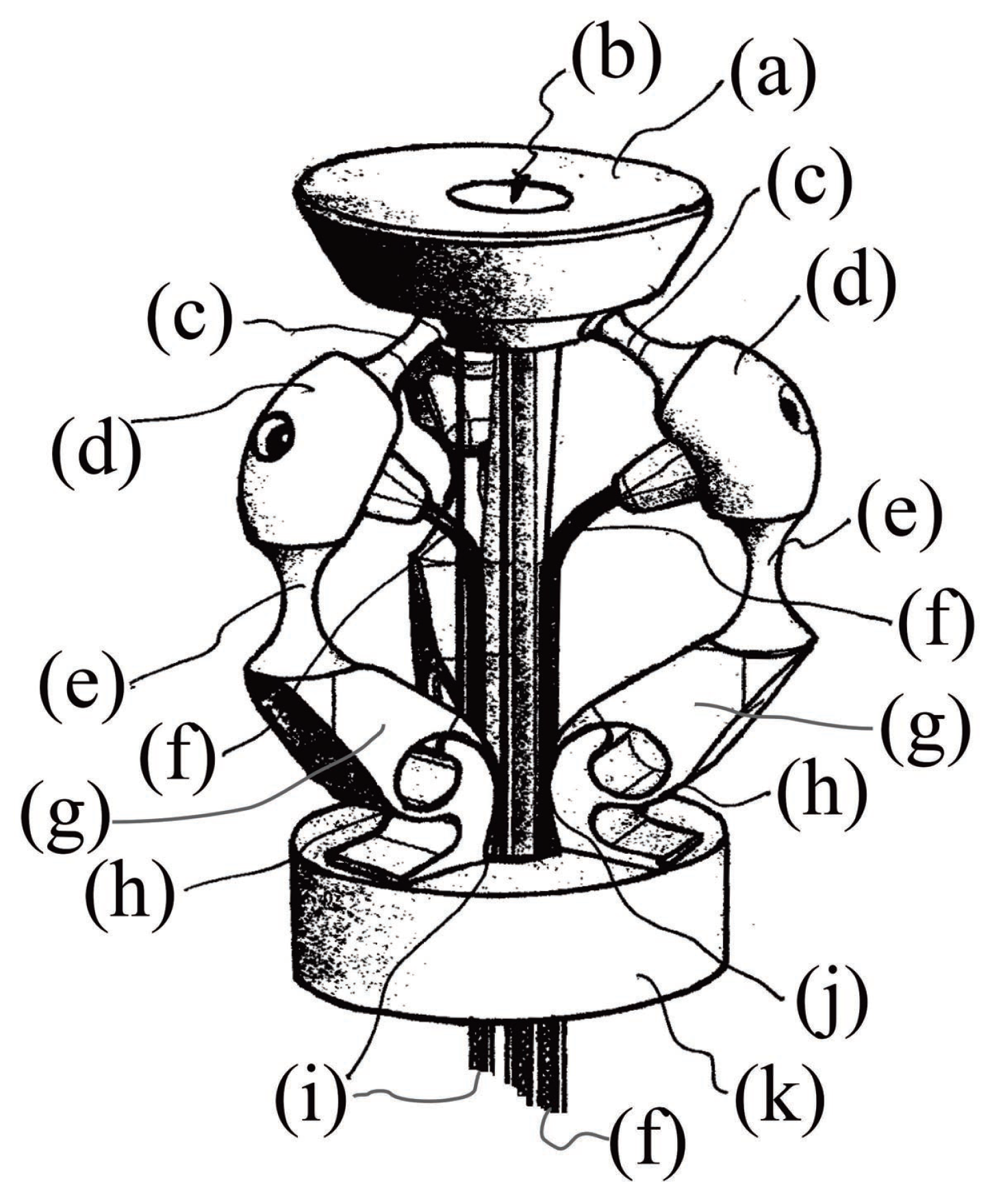
Figure 2.
The compliant platform (a) and its corresponding pseudo-rigid body mechanism (b), with the equivalent revolute joints R, spherical joints S, prismatic pairs P, a triple spherical joint , and the cable directions , , and .
Figure 2.
The compliant platform (a) and its corresponding pseudo-rigid body mechanism (b), with the equivalent revolute joints R, spherical joints S, prismatic pairs P, a triple spherical joint , and the cable directions , , and .
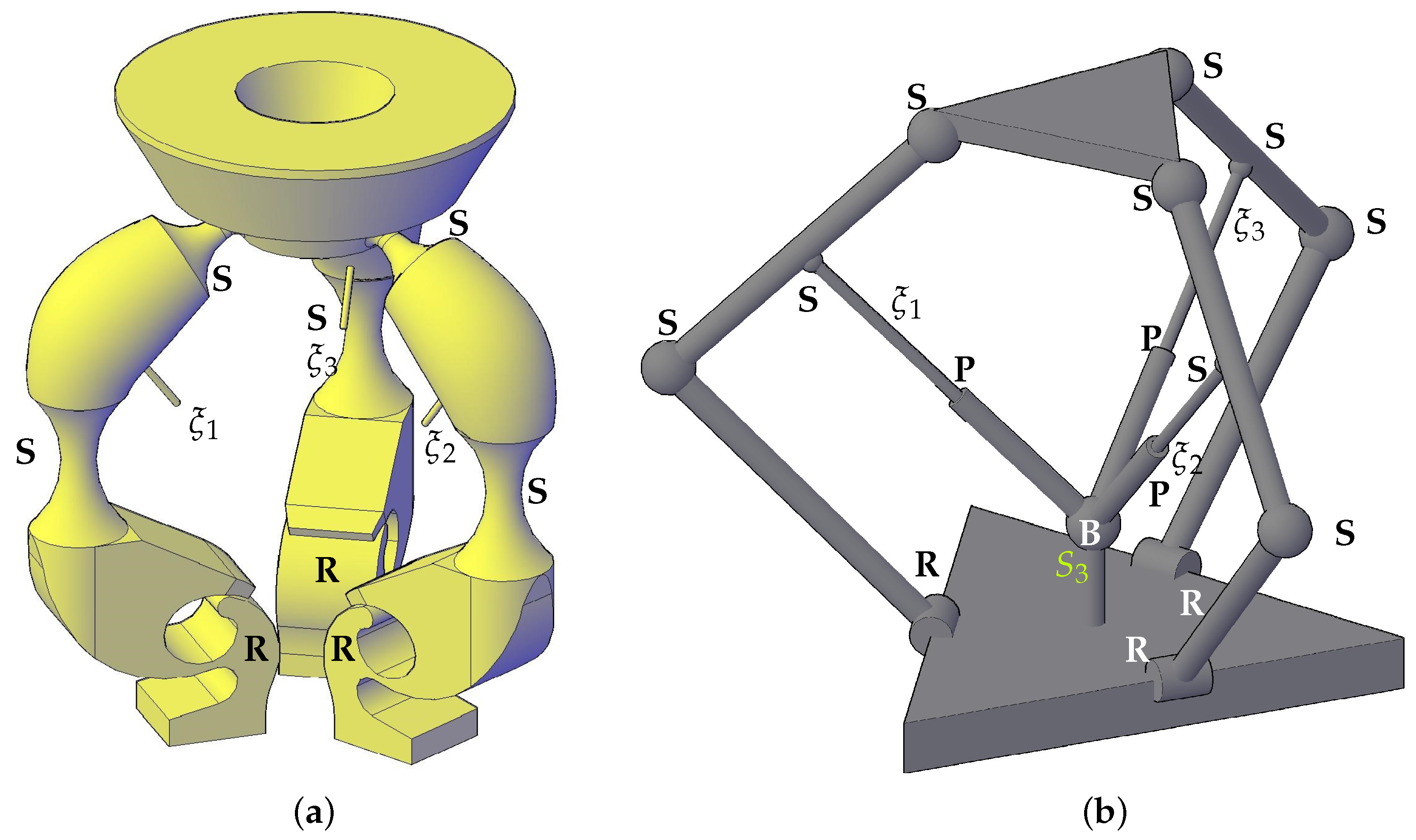
Figure 3.
(a) The circles and as loci of points and , respectively, for the ith leg; (b) the virtual bar rotating along the axis parallel to the line .
Figure 3.
(a) The circles and as loci of points and , respectively, for the ith leg; (b) the virtual bar rotating along the axis parallel to the line .
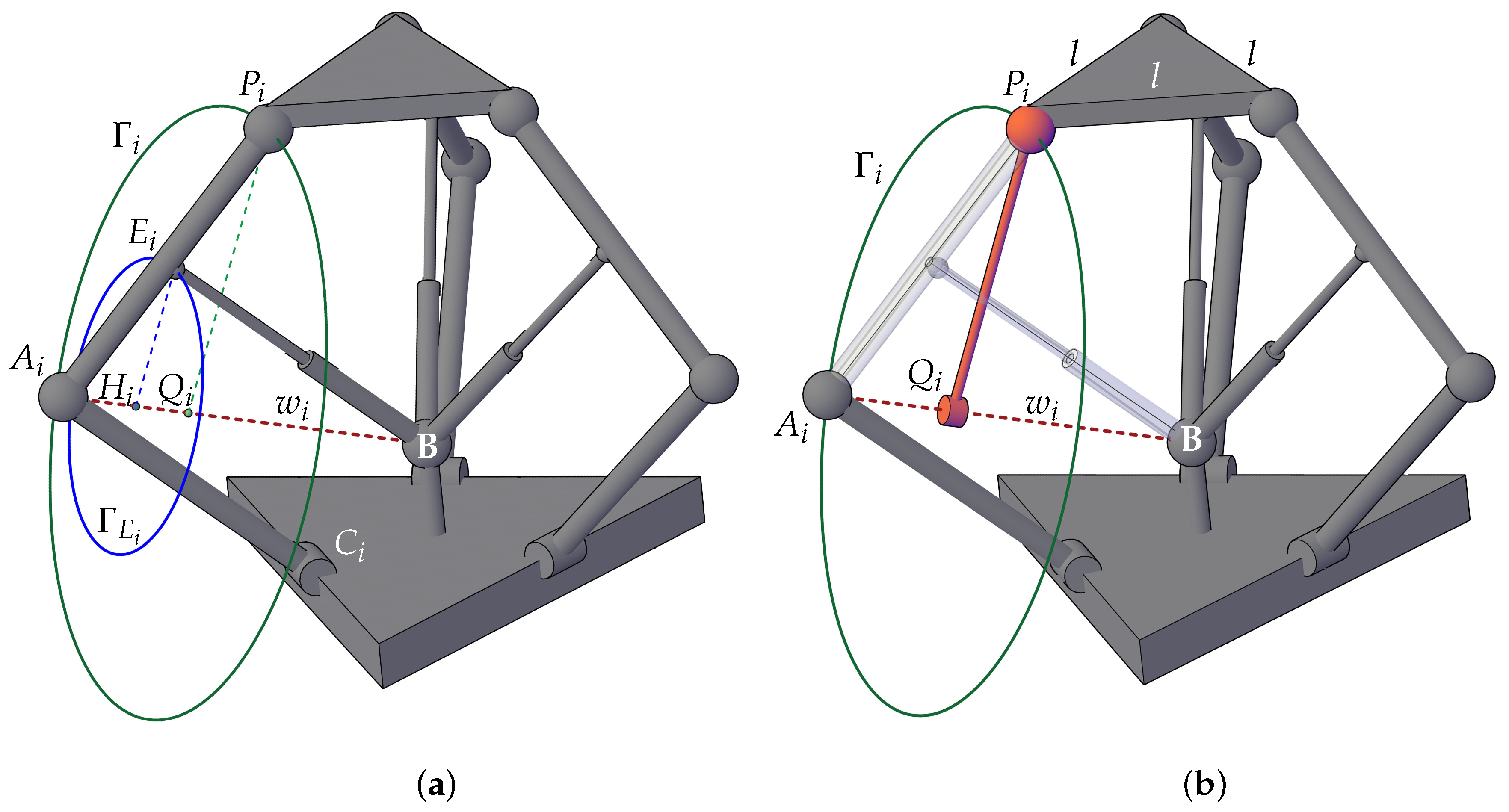
Figure 4.
The reduced parallel structure: points , axes and points .
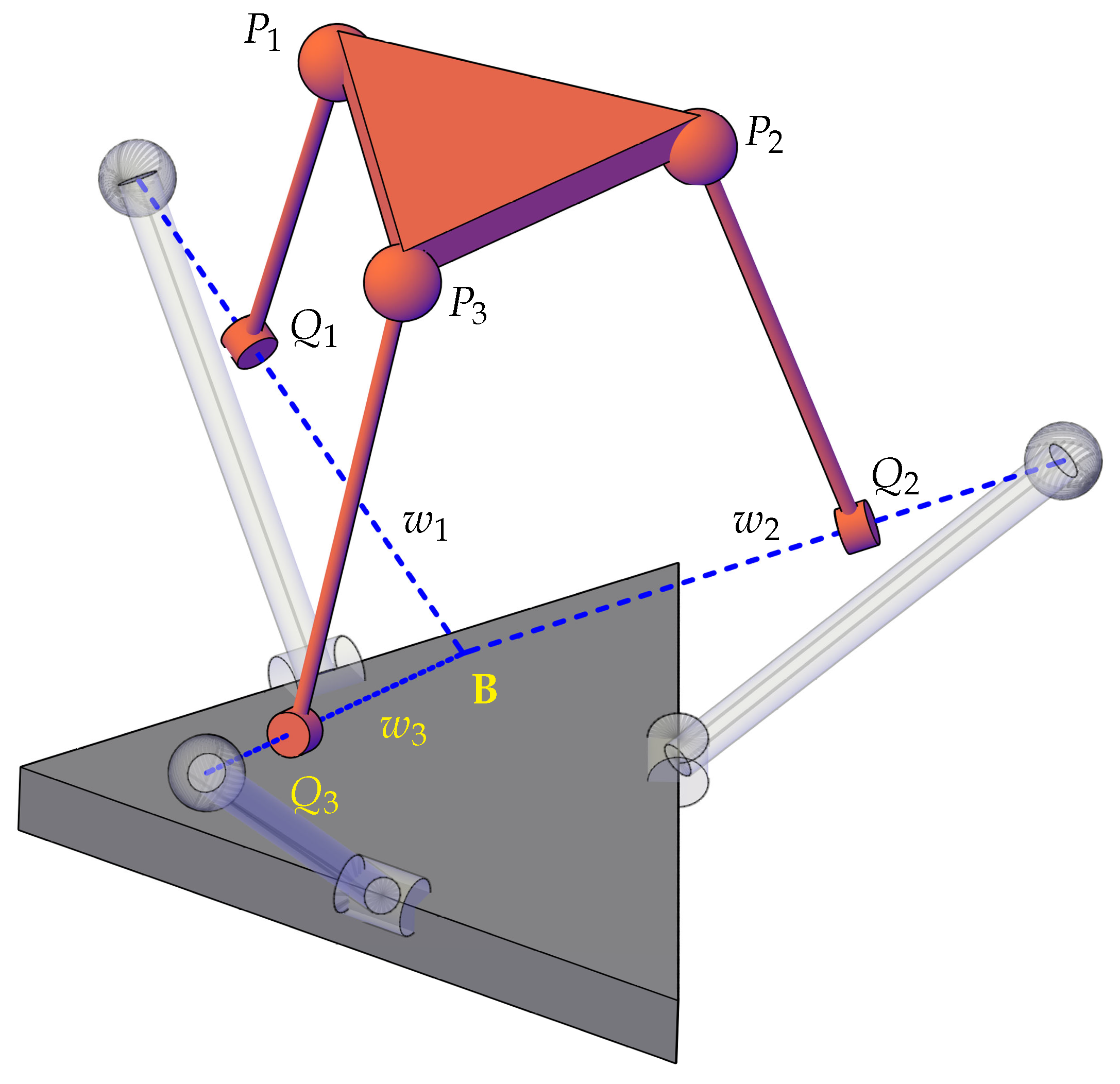
Figure 5.
(a) Reference frames and nomenclature; (b) platform displacement along the z-axis, negative direction (Case 1).
Figure 5.
(a) Reference frames and nomenclature; (b) platform displacement along the z-axis, negative direction (Case 1).
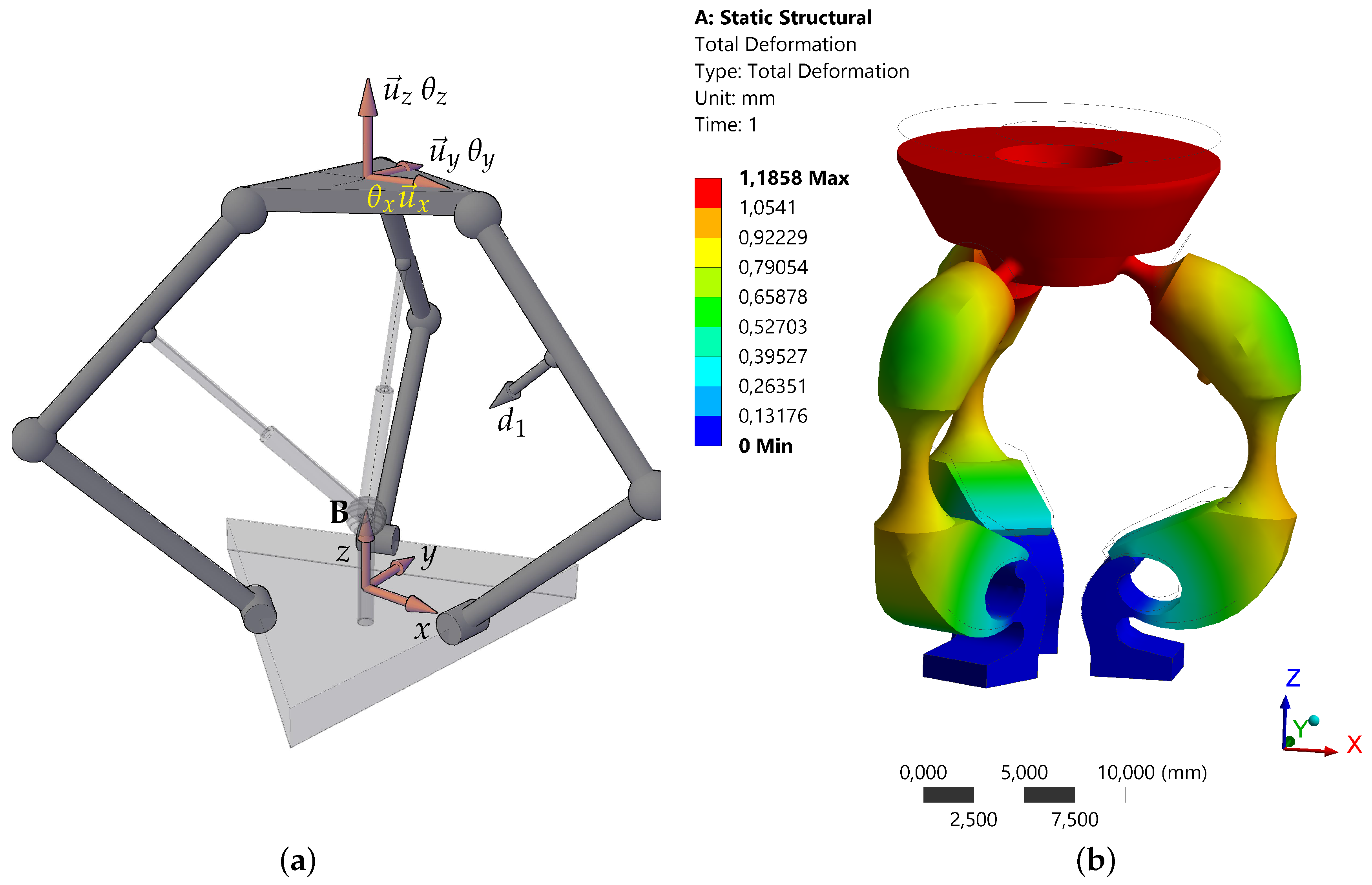
Figure 6.
(a) Platform displacement along the z-axis, positive direction (Case 2); (b) platform pose for a generic actuation scheme (Case 3).
Figure 6.
(a) Platform displacement along the z-axis, positive direction (Case 2); (b) platform pose for a generic actuation scheme (Case 3).
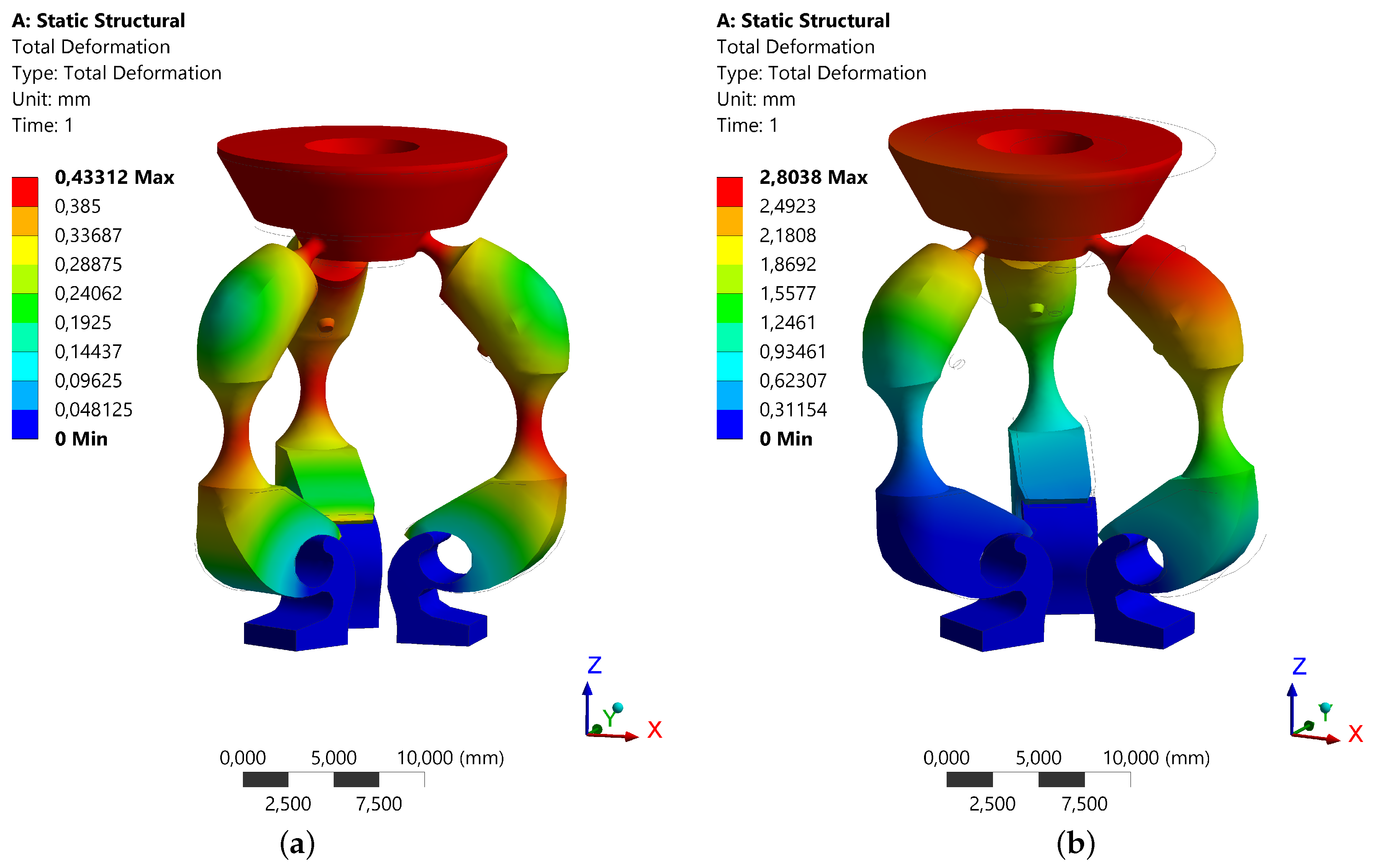
Figure 7.
A view of an end-effector mounted in the platform: catheter (a); base link (b); legs (c); platform (d); on-board hardware (e); on-board end-effectors (f) and (g).
Figure 7.
A view of an end-effector mounted in the platform: catheter (a); base link (b); legs (c); platform (d); on-board hardware (e); on-board end-effectors (f) and (g).


Table 1.
Input rotations and displacements and their effect on the platform for the three analyzed cases.
Table 1.
Input rotations and displacements and their effect on the platform for the three analyzed cases.
| Case 1 | Case 2 | Case 3 | |||
|---|---|---|---|---|---|
| Input | Output | Input | Output | Input | Output |
| mm | mm | mm | |||
| mm | mm | mm | |||
| mm | mm | mm | |||
| mm | mm | mm | |||
| mm | mm | mm | |||
| mm | mm | mm | |||
© 2019 by the author. Licensee MDPI, Basel, Switzerland. This article is an open access article distributed under the terms and conditions of the Creative Commons Attribution (CC BY) license (http://creativecommons.org/licenses/by/4.0/).
Share and Cite
MDPI and ACS Style
Belfiore, N.P. A New Concept Compliant Platform with Spatial Mobility and Remote Actuation. Appl. Sci. 2019, 9, 3966. https://doi.org/10.3390/app9193966
AMA Style
Belfiore NP. A New Concept Compliant Platform with Spatial Mobility and Remote Actuation. Applied Sciences. 2019; 9(19):3966. https://doi.org/10.3390/app9193966
Chicago/Turabian StyleBelfiore, Nicola Pio. 2019. "A New Concept Compliant Platform with Spatial Mobility and Remote Actuation" Applied Sciences 9, no. 19: 3966. https://doi.org/10.3390/app9193966
Note that from the first issue of 2016, this journal uses article numbers instead of page numbers. See further details here.