Direction for High-Performance Supercritical CO2 Centrifugal Compressor Design for Dry Cooled Supercritical CO2 Brayton Cycle

Abstract
:1. Introduction
2. Methodology
2.1. KAIST-TMD
2.2. Loss Models
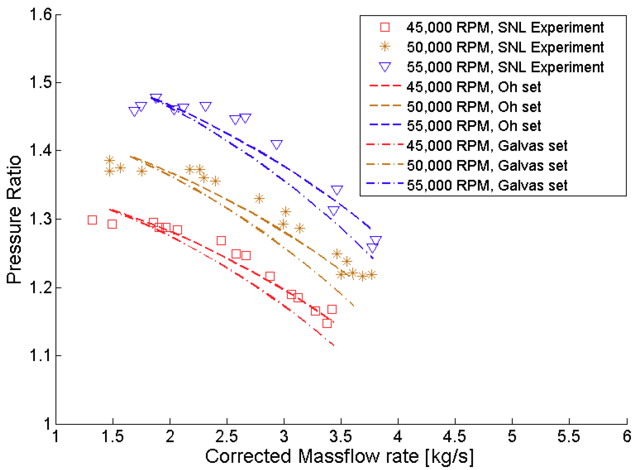
2.3. Loss Model Selection
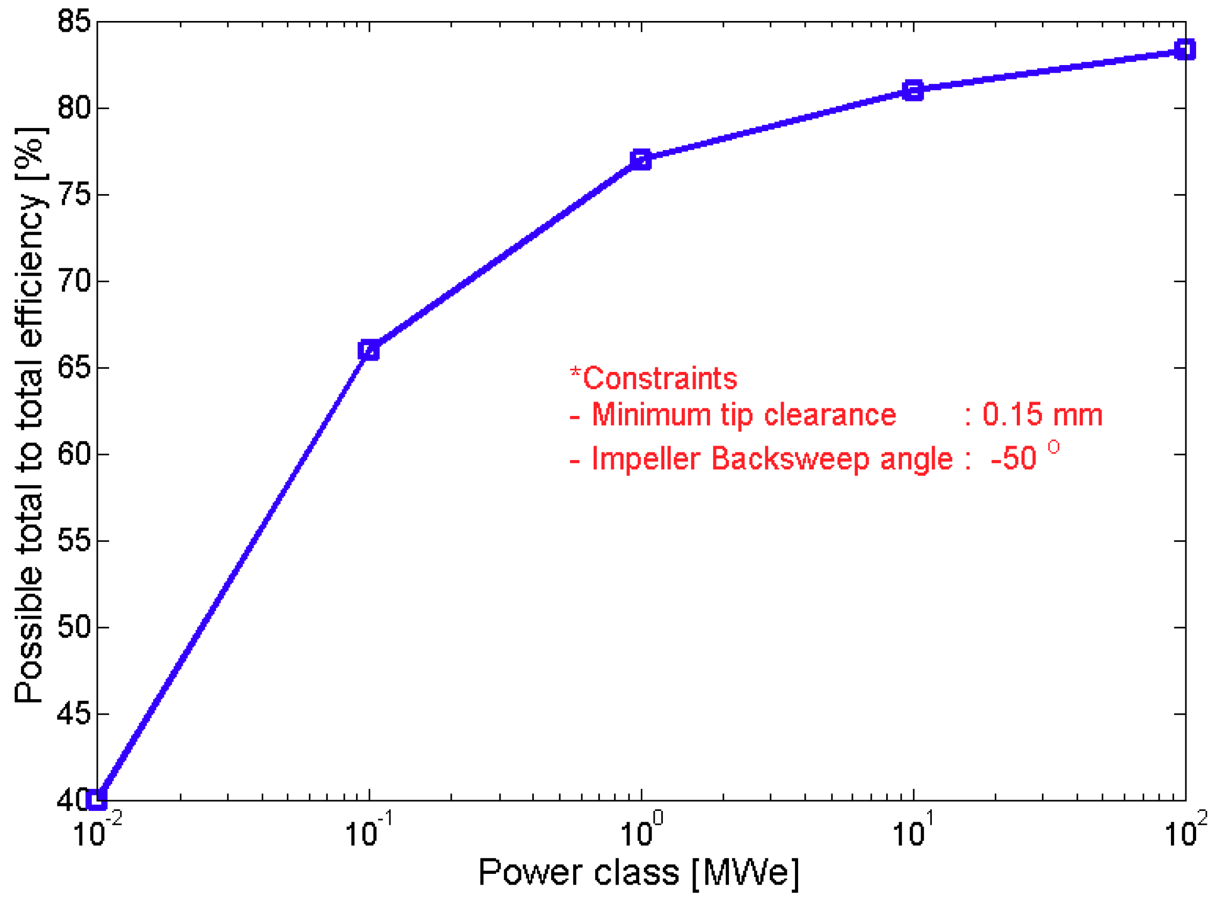
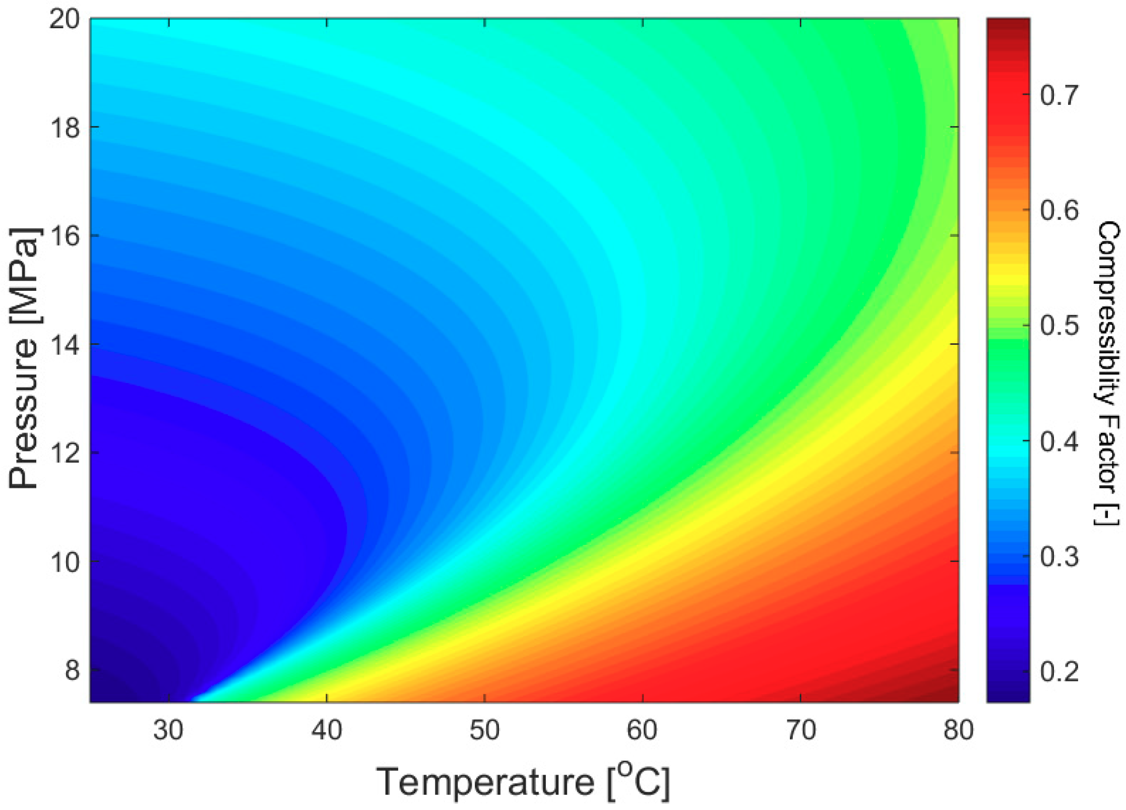
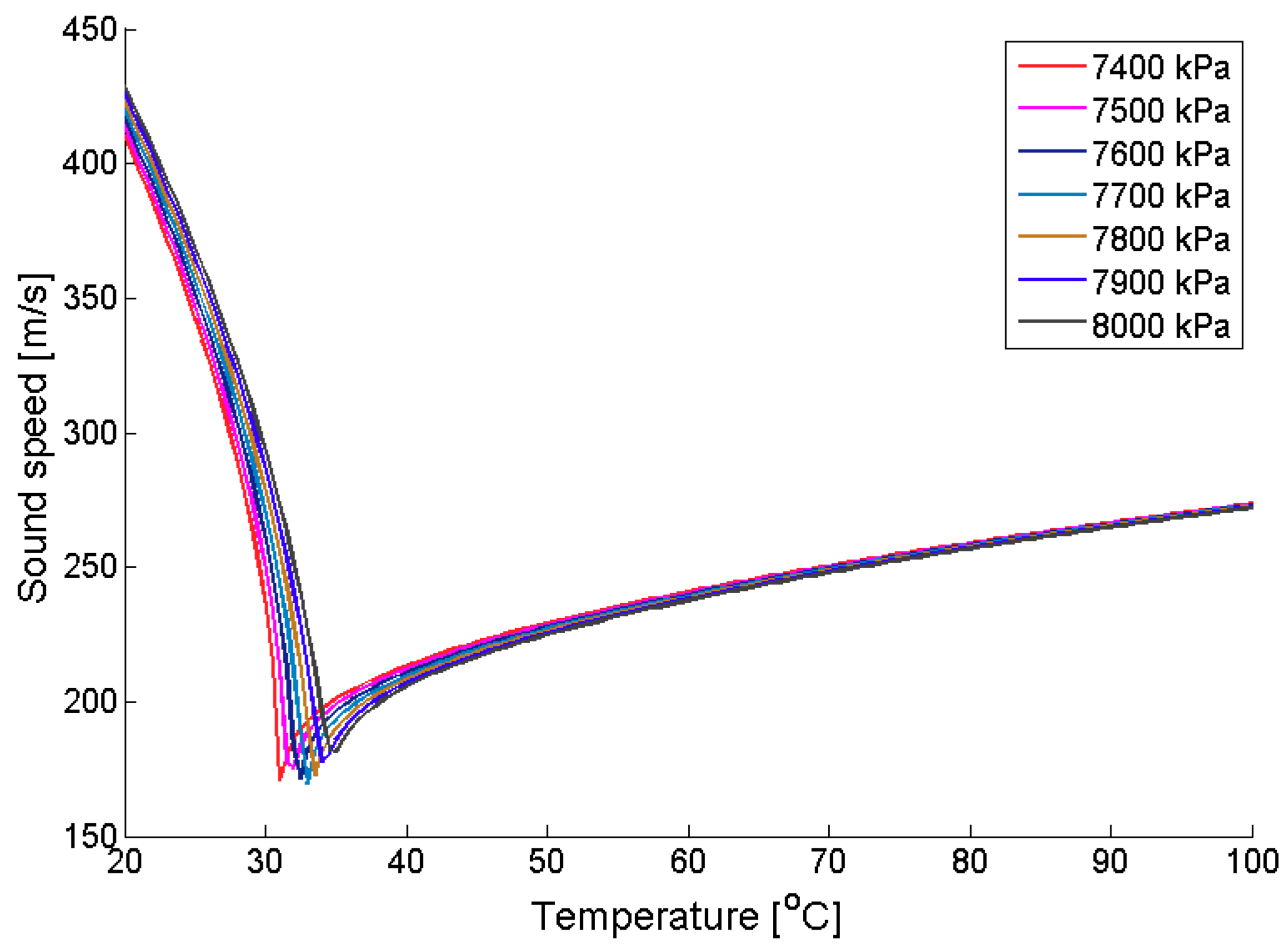
2.4. Selection of Analysis Conditions
3. Results
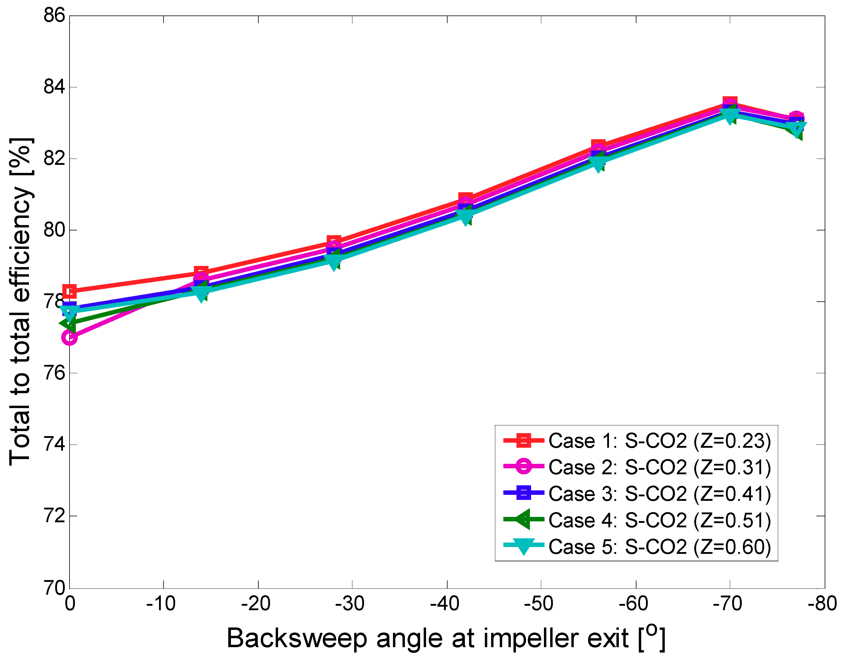
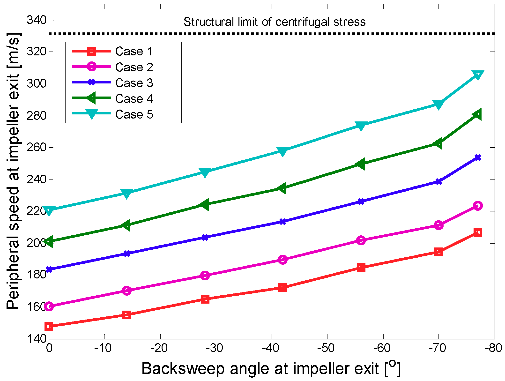
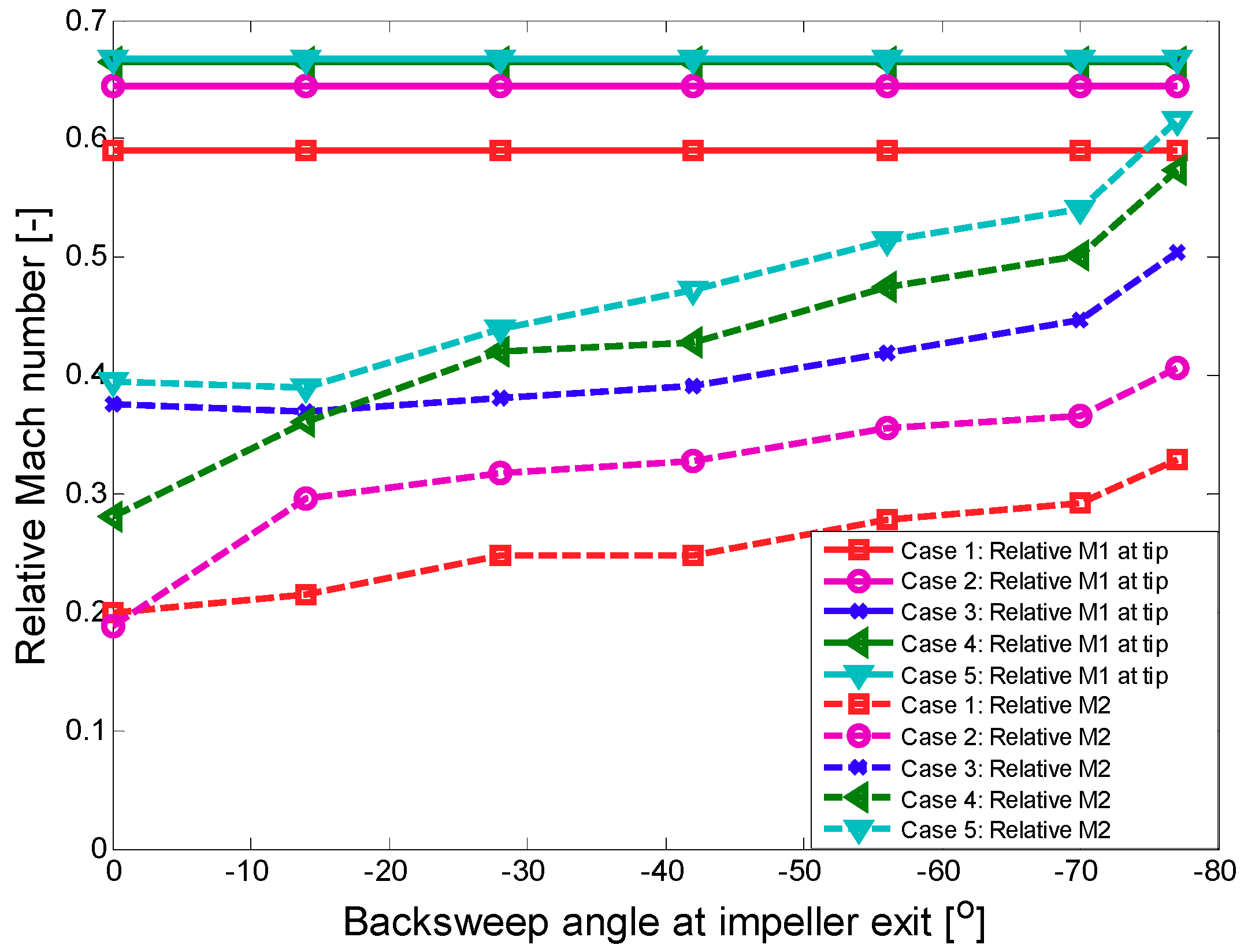
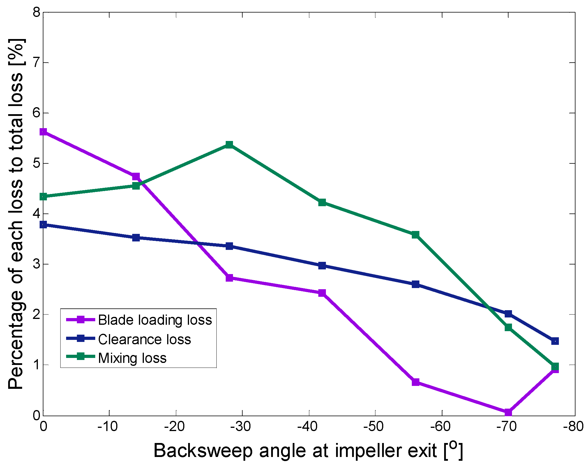
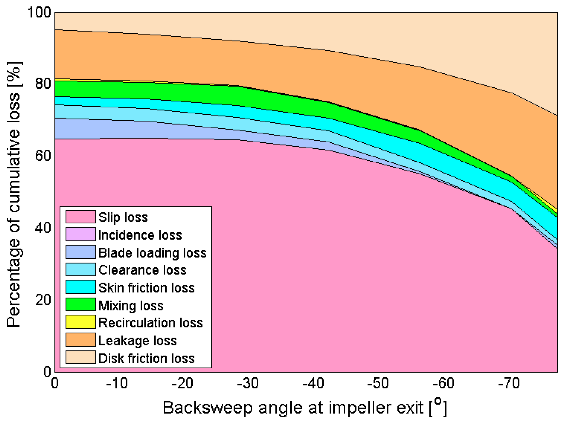
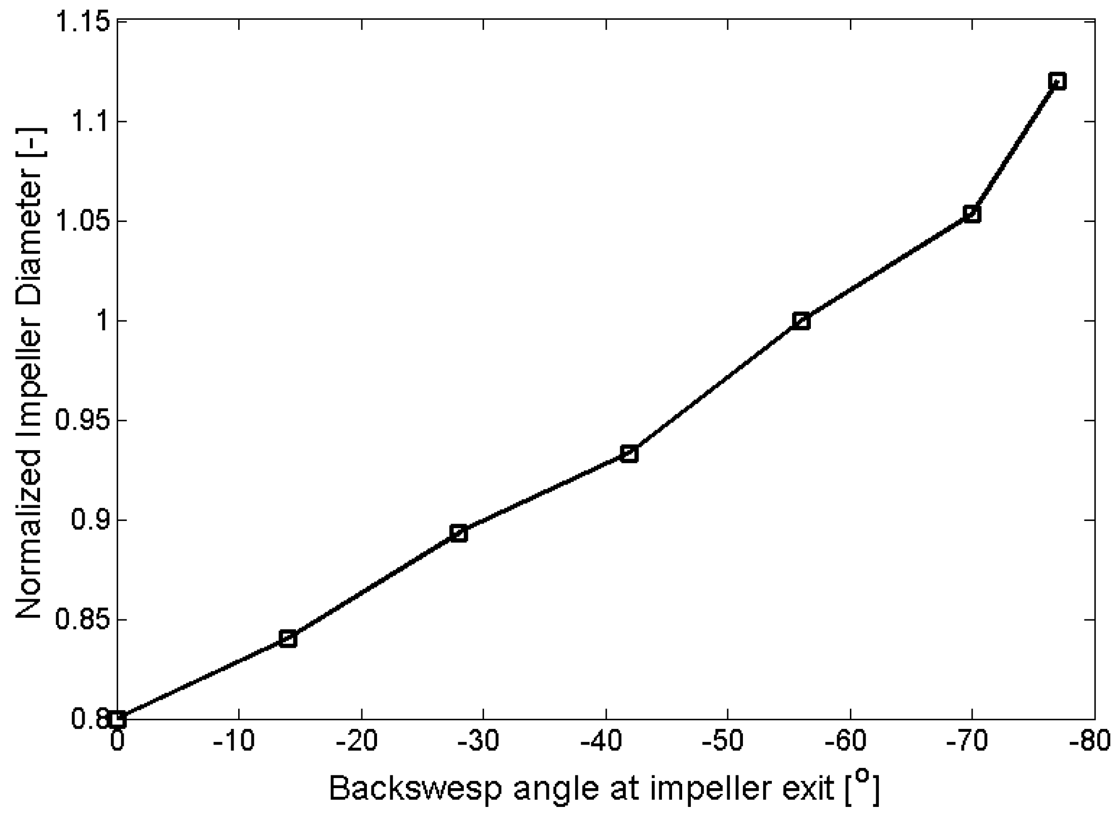
3.1. Effects of Large Backsweep Angle on S-CO2 Compressor Performance
3.2. Impact of Large Backsweep Angle S-CO2 Compressor on Cycle Performance
4. Conclusions
Author Contributions
Funding
Conflicts of Interest
Nomenclature
| C | Velocity |
| Cf | Friction coefficient |
| CP | Compressor |
| Had | Adiabatic head |
| HTR | High temperature recuperator |
| IHX | Intermediate heat exchanger |
| LTR | Low temperature recuperator |
| M | Mach number |
| MC | Main compressor |
| N | Rotational speed (rad/s) |
| P | Pressure |
| Pc | Critical pressure |
| PC | Pre-cooler |
| Q | Volumetric flow rate (m3/s) |
| RC | Recompressor |
| RCP | Recuperator |
| T | Temperature |
| TB | Turbine |
| Tc | Critical temperature |
| U | Tip speed or peripheral speed |
| V | Velocity |
| b | Ratio of vaneless diffuser inlet width to impeller exit width |
| beta2 | Backsweep angle at impeller exit |
| g | Gravitational acceleration |
| h | Enthalpy |
| ns | Specific speed |
| r | Radius |
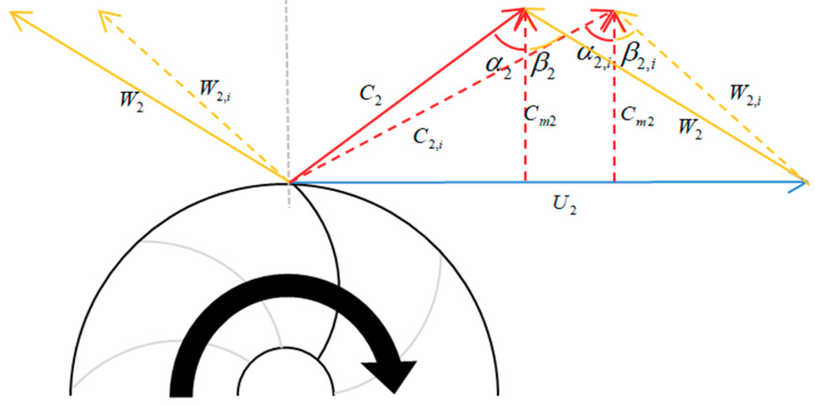
| α | Absolute angle to meridional direction |
| β | Relative angle to meridional direction |
| γ | Ratio of specific heats |
| ρ | Density |
| ϕ | Inclination of meridional streamline to machine axis |
| Subscript | |
| i | Ideal |
| m | Meridional component |
| o | Stagnation |
| s | Static |
| w | Tangential component |
| 0 | Zero backsweep angle |
| 1 | Impeller inlet |
| 2 | Impeller outlet |
References
- Ahn, Y.; Bae, S.J.; Kim, M.; Cho, S.K.; Baik, S.; Lee, J.I.; Cha, J.E. Review of Supercritical CO2 Power Cycle Technology and Current Status of Research and Development. Nucl. Eng. Technol. 2015, 47, 647–661. [Google Scholar] [CrossRef]
- Wagner, M.J.; Kustscher, C. The Impact of Hybrid Wet/Dry Cooling on Concentrating Solar Power Plant Performance. In Proceedings of the 4th International Conference on Energy Sustainability, Phoenix, AZ, USA, 17–22 May 2010. [Google Scholar]
- Turchi, C.S.; Ma, Z.; Neises, T.W.; Wagner, M.J. Thermodynamic Study of Advanced Supercritical Carbon Dioxide Power Cycles for Concentrating Solar Power Systems. J. Sol. Energy Eng. 2013, 135, 041007. [Google Scholar] [CrossRef]
- Conboy, T.M.; Carlson, M.D.; Rochau, G.E. Dry-Cooled Supercritical CO2 Power for Advanced Nuclear Reactors. In Proceedings of the ASME Turbo Expo 2014, Düsseldorf, Germany, 16–20 June 2014; p. V03BT36A001. [Google Scholar]
- Zeyghami, M.; Khalili, F. Performance improvement of dry cooled advanced concentrating solar power plants using daytime radiative cooling. Energy Convers. Manag. 2015, 106, 10–20. [Google Scholar] [CrossRef]
- Ma, Y.; Zhang, X.; Liu, M.; Yan, J.; Liu, J. Proposal and assessment of a novel supercritical CO2 Bryaton cycle integrated with LiBr absorption chiller for concentrated solar power applications. Energy 2018, 148, 839–854. [Google Scholar] [CrossRef]
- Wright, S.A.; Radel, R.F.; Vernon, M.E.; Rochau, G.E.; Pickard, P.S. Operation and Analysis of a Supercritical CO2 Brayton Cycle; SAND2010-0171; Sandia National Laboratories: Albuquerque, NM, USA, 2010.
- Cha, J.E.; Bae, S.W.; Lee, J.; Cho, S.K.; Lee, J.I.; Park, J.H. Operation Results of a Closed Supercritical CO2 Simple Brayton Cycle. In Proceedings of the 5th International Symposium-Supercritical CO2 Power Cycles, San Antonio, TX, USA, 28–31 March 2016. [Google Scholar]
- Lee, J.; Baik, S.; Cho, S.K.; Cha, J.E.; Lee, J.I. Issues in performance measurement of CO2 compressor near the critical point. Appl. Therm. Eng. 2016, 94, 111–121. [Google Scholar] [CrossRef]
- Conboy, T.; Wright, S.; Pasch, J.; Fleming, D.; Rochau, G.; Fuller, R. Performance Characteristics of an Operating Supercritical CO2 Brayton Cycle. J. Eng. Gas Turbines Power 2012, 134, 111703. [Google Scholar] [CrossRef]
- Conboy, T.M. Real-Gas Effects in Foil thrust Bearings Operating in the Turbulent Regime. J. Tribol. 2013, 135, 031703. [Google Scholar] [CrossRef]
- Cho, J.; Shin, H.; Ra, H.; Lee, G.; Roh, C.; Lee, B.; Baik, Y. Development of the Supercritical Carbon Dioxide Power Cycle Experimental Loop in KIER. In Proceedings of the ASME Turbo Expo 2016, Seoul, Korea, 13–17 June 2016; p. V009T36A013. [Google Scholar]
- David, P.K. Thee History and Future of the Centrifugal Compressor in Aviation Gas Turbines. SAE Int. 1984. [Google Scholar] [CrossRef]
- Talib, Z.F.; Mark, W.J. The Effect of Backswept Blading on the Flow in a Centrifugal Compressor Impeller. In Proceedings of the ASME Turbo Expo 1990, Brussels, Belgium, 11–14 June 1990. [Google Scholar]
- Takanori, S.; Yagi, M.; Nishida, H.; Kobayashi, H.; Tanaka, M. Performance Improvement of a Centrifugal Compressor Stage by Increasing Degree of Reaction and Optimizing Blade Loading of a 3D-Impeller. In Proceedings of the ASME Turbo Expo 2009, Orlando, FL, USA, 8–12 June 2009. [Google Scholar]
- Gray, D.V.; Ronren, G. Backswept Titanium Turbocharger Compressor Wheel. U.S. Patent Application Publication Pub. No.: US20060067829A1, 30 March 2006. [Google Scholar]
- Wang, Y.; Guenette, G.R.; Hejzlar, P. Aerodynamic Design of Turbomachinery for 300 MWe Supercritical Carbon Dioxide Brayton Power Conversion System; MIT-GFR-022; MIT Nuclear Energy Systems: Cambridge, MA, USA, March 2005. [Google Scholar]
- Span, R.; Wagner, W. A New Equation of State for Carbon Dioxide Covering the Fluid Region from the Triple-Point Temperature to 1100K at Pressures up to 800 MPa. J. Phys. Chem. Ref. Data 1994, 25, 1509–1596. [Google Scholar] [CrossRef]
- Lee, J.; Cho, S.; Lee, J.I. The Effect of Real Gas Approximations on S-CO2 Compressor Design. J. Turbomach. 2018, 140, 051007. [Google Scholar] [CrossRef]
- Lee, J.; Lee, J.I.; Yoon, H.J.; Cha, J.E. Supercritical Carbon dioxide turbomachinery design for water-cooled Small Modular Reactor application. Nucl. Eng. Des. 2014, 270, 76–89. [Google Scholar] [CrossRef]
- Dubitsky, O.; Japikse, D. Vaneless Diffuser Advanced Model. J. Turbomach. 2008, 130, 011020. [Google Scholar] [CrossRef]
- Martins, G.L. Axial Turbine Cascade Correlation. Appl. Sci. 2016, 6, 420. [Google Scholar] [CrossRef]
- Zhu, W.; REN, X.; LI, X.; GU, C. Analysis and Improvement of a Two-Stage Centrifugal Compressor Used in an MW-Level Gas Turbine. Appl. Sci. 2018, 8, 1347. [Google Scholar] [CrossRef]
- Lee, J. Study of Improved Design Methodology of S-CO2 Power Cycle Compressor for the Next Generation Nuclear System Application. Ph.D. Thesis, Korea Advanced Institute of Science and Technology, Daejeon, Korea, 2016; pp. 71–76. [Google Scholar]
- Aungier, R.H. Centrifugal Compressors: A Strategy for Aerodynamic Design and Analysis; ASME Press: New York, NY, USA, 2000. [Google Scholar]
- Oh, H.W.; Yoon, E.S.; Chung, M.K. An optimum set of loss models for performance prediction of centrifugal compressors. J. Power Energy 1997, 211, 331–338. [Google Scholar] [CrossRef]
- Galvas, M.R. Fortran Program for Predicting Off-Design Performance of Centrifugal Compressors, NOV; National Aeronautics and Space Administration (NASA): Greenbelt, MD, USA, 1973.
- Daily, J.W.; Nece, R.E. Chamber dimension effects on induced flow and frictional resistance of enclosed rotating disks. J. Basic Eng. 1960, 82, 217–230. [Google Scholar] [CrossRef]
- Nemdili, A.; Hellmann, D. Development of an Empirical Equation to Predict the Disc Friction Losses of a Centrifugallp Pump. In Proceedings of the 6th International Conference on Hydraulic Machinery and Hydrodynamics, OCT, Timisoara, Romania, 21–22 October 2004. [Google Scholar]
- Balje, O.E. Turbomachines: A Guid to Design, Selection, and Theory; A Wiley Interscience Publication: NewYork, NY, USA, 1980. [Google Scholar]
- Sienicki, J.J.; Moisseytsev, A.; Fuller R, L. Scale Dependencies of Supercritical Carbon Dioxide Brayton Cycle Technologies and the Optimal Size for a Next-Step Supercritical CO2 Cycle Demonstration. In Proceedings of the International Symposium-Supercritical CO2 Power Cycles, Boulder, CO, USA, 24–25 March 2011. [Google Scholar]
- Son, S.; Lee, J.I. Application of adjoint sensitivity analysis method to supercritical CO2 power cycle optimization. Energy 2018, 147, 1153–1164. [Google Scholar] [CrossRef]


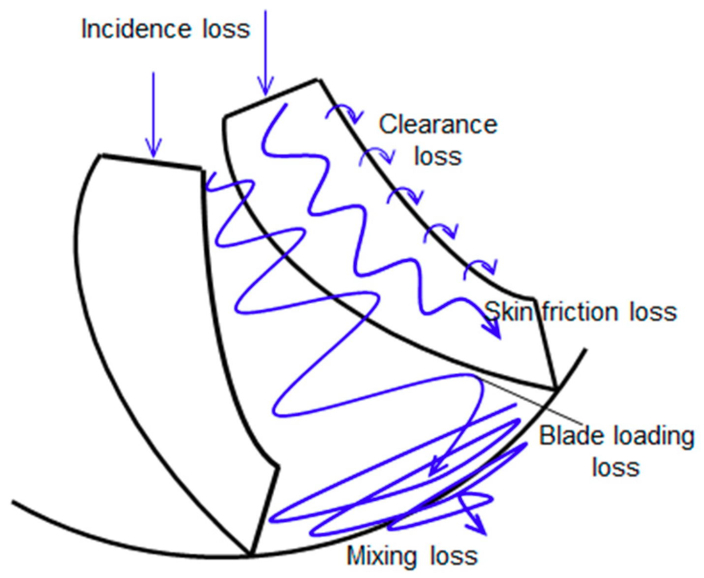
| Classification of Loss Type | Model | |
|---|---|---|
| Internal loss | Incidence loss | Conrad |
| Blade loading loss | Coppage | |
| Skin friction loss | Jansen | |
| Clearance loss | Jansen | |
| Mixing loss | Johnston and Dean | |
| Slip loss | Wiesner | |
| External loss | Leakage loss | Aungier |
| Recirculation loss | Oh | |
| Disk friction loss | Nemdili | |
| Design Conditions | |||||
|---|---|---|---|---|---|
| Case Number | Case 1 | Case 2 | Case 3 | Case 4 | Case 5 |
| Working fluid | S-CO2 | S-CO2 | S-CO2 | S-CO2 | S-CO2 |
| Target total pressure [MPa] | 20 | 20 | 20 | 20 | 20 |
| Compressibility factor [-] | 0.23 | 0.31 | 0.41 | 0.51 | 0.60 |
| Inlet static temperature [°C] | 31 | 33 | 32 | 36 | 45 |
| Inlet static pressure [MPa] | 7.4 | 7.7 | 7.4 | 7.4 | 7.4 |
| Design Parameters | |||||
| Compressor type | Radial type | Impeller type | Unshrouded | ||
| Ratio of inlet hub to shroud | 0.2 | Tip clearance [mm] | 0.15 | ||
| Number of full blades | 14 | Specific speed [-] | 0.64 | ||
| Impeller inlet absolute angle | 0° | Impeller outlet backsweep angle | 0~−77° | ||
| Ratio of impeller radius to vaneless space radius | 1.05 | Ratio of impeller blade height to diffuser blade height | 1.00 | ||
| Cycle Design Results | |||||
|---|---|---|---|---|---|
| Case Number | Case 1 | Case 2 | Case 3 | Case 4 | Case 5 |
| Generating power [MWe] | 10.0 | 9.97 | 10.1 | 9.95 | 9.56 |
| Cycle efficiency [%] | 33.4 | 33.2 | 33.7 | 33.1 | 31.9 |
| Cycle Design Constraints | |||
|---|---|---|---|
| Maximum Pressure [MPa] | 20 | [%] | 90 |
| TIT [°C] | 350~750 | of recuperators [%] | 95 |
| Pressure drop in heat exchangers [MPa] | 0.15 | Generator efficiency [%] | 98 |
| [%] | 81/84 | CIT [°C] | 31~70 |
© 2019 by the authors. Licensee MDPI, Basel, Switzerland. This article is an open access article distributed under the terms and conditions of the Creative Commons Attribution (CC BY) license (http://creativecommons.org/licenses/by/4.0/).
Share and Cite
Cho, S.K.; Bae, S.J.; Jeong, Y.; Lee, J.; Lee, J.I. Direction for High-Performance Supercritical CO2 Centrifugal Compressor Design for Dry Cooled Supercritical CO2 Brayton Cycle. Appl. Sci. 2019, 9, 4057. https://doi.org/10.3390/app9194057
Cho SK, Bae SJ, Jeong Y, Lee J, Lee JI. Direction for High-Performance Supercritical CO2 Centrifugal Compressor Design for Dry Cooled Supercritical CO2 Brayton Cycle. Applied Sciences. 2019; 9(19):4057. https://doi.org/10.3390/app9194057
Chicago/Turabian StyleCho, Seong Kuk, Seong Jun Bae, Yongju Jeong, Jekyoung Lee, and Jeong Ik Lee. 2019. "Direction for High-Performance Supercritical CO2 Centrifugal Compressor Design for Dry Cooled Supercritical CO2 Brayton Cycle" Applied Sciences 9, no. 19: 4057. https://doi.org/10.3390/app9194057